the and certification systems
TRANSCRIPT

CERTIFICATIONSYSTEMS
THE
AND


nord americano
xxxxxxxxxxxxxxxxxxxxxxxxxxxxxxxx
1. Foreword page 5
2. The classification of hazardous locations page 7
3. The north american approach page 8
3.1. Analysis of the north
american approach page 10
3.1.1. The types of hazardous locations page 10
3.1.2. The conditions
of hazardous locations page 11
3.1.3. The nature
of hazardous substances page 12
3.1.4. Review page 13
4. The european and international approach page 14
4.1. Analysis of the european
and international approach page 14
4.1.1. Types of hazardous locations page 14
4.1.2. The conditions
of hazardous locatons page 15
4.1.3. The nature
of hazardous substances page 17
4.1.4. Review page 17
5. The comparison between the two methods page 19
6. The product certification page 23
7. The standards supporting
certification page 25
IND
IEX
the iec and nec® certification systems 3


5 the iec and nec® certification systems
1.Foreword
C onformity to the Atex Directive is a necessary and sufficient condition in European Union coun-tries for the installation of protected electrical equipment in areas classified as hazardous. In
Countries that do not belong to the European Union, but belong to IECEx, protected electrical equipment is still subject to assessment of conformity to the standards of the IECEx system (International Electrotechnical Com-mission System for Certification to Standards Relating to Equipment for use in Explosive Atmospheres), both for general parts and for parts related to protection methods, by a third party entity. This is a voluntary certification scheme of an international character which, in its philosophy, is very similar to the ATEX Directive and calls for both design (Ex-TR) and manufacturing control (QAR) by a Certification Body accredited by this scheme; the certificate of conformity (CoC) may be applied for with these two documents. The regulatory framework is that of the IEC 60079 and IEC 61241 series.
The aim of the IECEx System is to support international trade in equipment intended for environments with explosive atmospheres, maintaining the necessary level of safety:
• reduction in test and certification costs for the manufacturer;• reduction in time to market;• international trust in the product assessment process;• an international database;• maintaining an international level of trust towards equipment and services subject to IECEx certification.
This scheme, as well as its certificates, is recognised by an ever increasing number of Countries internationally. The cer-tificates issued by the IECEx system are issued as "electronic certificates" and are available on the IECEx website. This allows the public to access them for viewing and printing them.
A similar but not identical system is in force on the other side of the world, the NEC system. The pur-pose of this document is to draw a comparison be-tween internationally used (IECEx) and US (NEC) classification of locations with explosive atmos-phere, whether formed by gas and air or combustible dust and air mixtures.The American classification and marking use the method of Classes and Divisions, unlike the Euro-pean ATEX praxis and the international IEC one that uses the Zone method. However, article 505 of NEC offers the opportunity of a choice in the way of clas-sifying with the aim of giving to the IECEx system worldwide recognition and support free circulation of equipment suited for the zones classified accord-ing to the IECEx system.
NEC-Standard IEC-Standard Entrambi gli standard
Fig.1 Geographic dissemination of NEC and IEC standards

the iec and nec® certification systems 6 the iec and nec® certification systems
This means that products may be approved: • either by Class, Division and Group of Substances
For instance: Class 1, Division 2, A,B,C,D T3; • or by Class, Division and Group of Gas
For instance: Class 1, Zone 2, IIA, IIB, IIC T3. Figure 1 on the previous page describes the geographical spread of NEC and IECEx standards, highlighting also those Countries where both are valid and applicable. To help you to quickly comprehend the acronyms we have used in the text, Table 1 below provides a key to their meaning.
Tab. 1 The main acronyms and their meaning
me
an
ing
acronimo acronimo acronimo acronimo acronimo
ANSI
American National Standards
Institute
CAS
Chemical Abstracts Service
FM
Factory Mutual approval standard
EN
European standard
BIA
Berufsgenossenschaf-tliches Institut
für Arbeitsschutz
IEC
International Electrotechnical
Commission
IECEx
IEC system for certification
to standards relating to equipment for use
in explosive atmospheres
(IECEx system)
MESG
Maximum Experimental
Safe Gap
ISA
International Society
of Automation
IECEE
IEC System of Conformity
Assessment Schemes for Electrotechnical
Equipment and Componentsm
ea
nin
g
MIC
Minimum Ignition Current
NFPA®
National Fire Protection Association®
NANDO
New Approach Notified
and Designated Organisations
ONU
Organizzazione delle Nazioni
Unite
NEC®
National Electrical Code®
me
an
ing
NRTL
Nationally Recognized
Testing Laboratory
UL
Underwriters Laboratories
UNECE
United Nations Economic
Commission for Europe
OSHA
Occupational Safety
and Health Administration
me
an
ing
Foreword 1.
the iec and nec® certification systems 7
of hazardous locations2.The classification
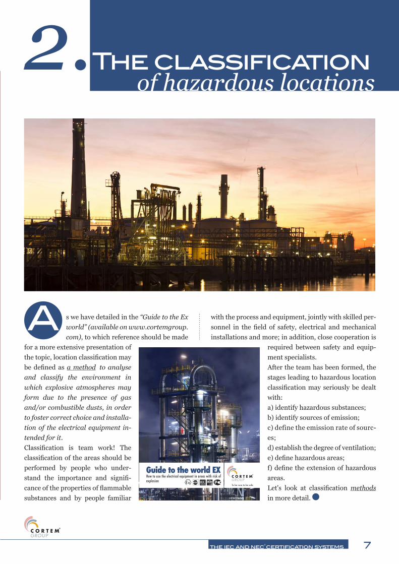
A s we have detailed in the “Guide to the Ex world” (available on www.cortemgroup.com), to which reference should be made
for a more extensive presentation of the topic, location classification may be defined as a method to analyse and classify the environment in which explosive atmospheres may form due to the presence of gas and/or combustible dusts, in order to foster correct choice and installa-tion of the electrical equipment in-tended for it. Classification is team work! The classification of the areas should be performed by people who under-stand the importance and signifi-cance of the properties of flammable substances and by people familiar
with the process and equipment, jointly with skilled per-sonnel in the field of safety, electrical and mechanical installations and more; in addition, close cooperation is
required between safety and equip-ment specialists. After the team has been formed, the stages leading to hazardous location classification may seriously be dealt with:a) identify hazardous substances;b) identify sources of emission;c) define the emission rate of sourc-es;d) establish the degree of ventilation;e) define hazardous areas;f) define the extension of hazardous areas. Let's look at classification methods in more detail.
Guide to the world EXHow to use the electrical equipment in areas with risk of explosion

nord americano
8 the iec and nec® certification systems
cations and equipment and communication systems. We might say that, just as for us Europeans the har-monised standards are the reference state of the art that is also valid in jurisprudence, the same applies to US citizens with the National Electrical Code®.The NEC® also contains information on the offi-cial definition of Hazardous Locations and related standards supplied by the Occupational Safety and Health Administration (OSHA) which provides legal status to the NEC® and its application.A substantial part of the NEC® (Chapter 5: special locations) is dedicated to hazardous locations in which electrical equipment may become a source of ignition. Let's look at articles concerning Ex issues in more detail.
T he North American approach, and more specifically the US one, is based on the “National Electrical
Code” (NEC®).The National Electrical Code®, or NFPA 70®, is a standard that may be implemented regionally in the US for safe installation of equipment and its wiring. It belongs to the set of National Fire Codes pub-lished by the National Fire Protection Association (NFPA). The NEC® is approved as a national Ameri-can standard by the American National Standards Institute (ANSI) and is formally identified as ANSI / NFPA 70.The National Electrical Code® is divided into chap-ters that deal with topics such as: wiring and rele-vant methods, equipment for general use, special lo-
3.The north american
art.500Hazardous locations (classified), Classes I, II and III, Divisions 1 and 2.Provides the basis for interpretation and correct application of articles from 501 to 517.
art.502Class II locations.Article 502 concerns requirements for electrical and electronic equipment for all voltages and relevant wirings of Class II locations, Division 1 and 2 where fires or explosions could occur due to combustible dusts.The following sub-articles are present:I: overview;II: wirings;III: equipment.
art.503Class III locations.Article 503 concerns requirements for electrical and electronic equipment for all voltages and relevant wirings of Class III locations, Division 1 and 2 where fires or explosions could occur due to ignitable fibres.The following sub-articles are present:I: overview;II: wirings;III: equipment.
art.501Class I locations.Article 501 concerns requirements for electrical and electronic equipment for all voltages and relevant wirings of Class I locations, Division 1 and 2 where fires or explosions could occur due to flammable gases or vapours or flammable liquids.The following sub-articles are present:I: overview;II: wirings;
III: equipment.
approach

9 the iec and nec® certification systems
The north american approach3.art.504
Intrinsic safety systems.Article 504 concerns the installation of intrinsic safety equipment, and wiring them in Class I, II and III areas.
art.505Locations of Zone 0, 1 and 2.It covers the requirements for the classification system in Zones (Zone 0, 1, and 2) as an alternative to the classification system in divisions covered under article 500 for Class I;
art.506Zone 20, 21 and 22 locations for combustible dusts or ignitable fibres.It covers the requirements for the classification system in Zones (Zone 20, 21, and 22) as an alternative to the classification system in Divisions covered under articles 500, 502 and 503 for Classes II and III; combustible metal dusts are not covered by this article.
art.510Hazardous locations (classified) - specific features.Articles from 511 to 517 cover the locations or parts of locations that are or may be hazardous due to atmospheric concentrations of flammable liquids, gases or vapours, or due to deposits or accumulations of materials that might be easily ignited.
art.511Commercial, repair and storage garages.These locations include those used for maintenance and repair of motor vehicles equipped with their own engine (including, but not limited to, cars, buses, trucks and tractors) where volatile flammable liquids or flammable gases are used as fuel.
art.513This article applies to hangars where aircraft are parked containing Class I (flammable) or Class II (fuels) liquids whose temperatures are higher than the flash point. In these locations aircraft undergo maintenance, repair or modification operations. It does not apply to locations exclusively used for aircraft that have never contained fuel or aircraft discharged of fuel.
art.514Fuel dispensing installations.This article applies to fuel dispensing equipment, to distribution facilities of motor fuels, including for maritime use, fuel dispensing facilities located within buildings and facilities for dispensing fuel for vehicle fleets.
art.515Systems with large amounts in storage.This article applies to a property or portion of property in which flammable liquids are received from a tanker ship, from pipes, a car tank or tanker truck and are deposited or mixed in large quantities in order to distribute these liquids by tank vessel, piping, car tanks, tanker trucks, portable tank or container.
art.516Spray, immersion, coating application processes.This article concerns the regular or frequent application of flammable liquids, combustible liquids and combustible dust from spraying and application of flammable or combustible liquids at temperatures above their flash point, by means of dipping, coating or other means.
art.517Health service facilities.The provisions of this article apply to electrical constructions and installation criteria in health facilities that provide services to human beings.

10 the iec and nec® certification systems
3.1. Analysis of the north american approachIn the first instance we might say that, beyond some spe-cific locations identified from art. 511 to art. 517, the North American approach adopts two classification systems of hazardous locations that it deems as equivalent:• that of the two Divisions, traditionally used, (art.
from 500 to 503) which refers to its own set of stand-ards. For instance, for flame-proof enclosures standard FM class 3615 or standard ISA S12.22.01 or standard UL 1203;
• that of the three Zones (art. 505 and 506), which in its turn refers to a whole set of standards. For instance, for flame-proof enclosures standard IEC 60079-1.
Let us turn now to analysing the former classification sys-tem and we will deal with the analysis of articles 505 and 506 and European and international approach in the next paragraph.If we analyse articles from 500 to 503, NEC® classifies hazardous locations taking into account three criteria: the type, condition and nature.
3.1.1. The types of hazardous locationsa) Class I locationsAccording to NEC®, there are three types of hazardous loca-tion. The first type of hazard is that created by the presence of flammable gases or vapour in the air, such as natural gas or petrol vapours. When these materials are in the atmos-phere, there is a potential risk of explosion caused by ignition from an electrical source or other type of source. The authors of NEC® have defined this first type of hazard “Class I”. A Class I hazardous location is where flammable gases or va-pours may be in the air in a sufficient amount to be explosive or flammable. Some typical Class I locations are:
oil refineries
fuel storage areas
fuel dispensing areas
spray finishing areas
hangars and maintenance areas where fuels are used
gas systems and gas, liquefied petrol and natural gas storage and handling opera-tions
b) Class II locationsThe National Electrical Code® identifies “Class II” locations as areas where the danger is represented by combustible dusts. Finely pulverised material, sus-pended in the atmosphere, may cause one or more powerful explosions such as those occurring in an oil refinery, if not more catastrophic. Some typical Class II locations are:
cereal silos
flour and feed mills
producers of plastic materials, drugs and fireworks
producers of starch or confectionery
The north american approach3.

11 the iec and nec® certification systems
spice grinding, sugar and cocoa production systems
c) Class III locationsHazardous Class III locations, according to the NEC®, are areas where there are fibres or “solid combusti-ble particles” (flyings) that are easily flammable, due to the types of materials processed, stored or trans-formed. The fibres and solid particles are not likely to be suspended in the air, but may accumulate around a machine or on lighting fixtures and be triggered by heat, by a spark or a hot metal. Some typical Class III locations are:
textile and cotton gin factories
systems that form, pulverise or cut wood and create sawdust or "solid particles"
3.1.2. The conditions of hazardous locationsIn addition to the types of hazardous locations, the National Electrical Code® also deals with the type of conditions where these hazards are pre-sent: normal conditions or abnormal conditions. In the normal condition, the risk is present in day-to-day production operations or during the frequent repair and maintenance activity.When the hazardous material is confined within closed containers or closed systems and may only be present following accidental rupture, breakdown or unusual faulty operation, the condition is defined as abnor-mal.The authors of the NEC® have defined these two types of conditions very simply: Division 1 – normal and Division 2 – abnormal. All the classes (I, II and III) may be Division 1 or Division 2.Class I, Division 1 locations are, for instance, ar-eas next to safety valves in an oil refinery or areas close to open loading structures such as those that
are created during fuel transfer from/to tanker truck/tank. In these locations, the hazardous ma-terial is present during normal system operations (Fig. 2).
Fig.2 Classification of hazardous locations during fuel transfer operations
Storage drums containing flammable liquids closed in an internal deposit do not normally allow hazardous vapours to escape into the atmosphere. But what hap-pens if one of the containers has leaks? There would be a Division 2 – abnormal condition, more precisely Class I, Division 2 (Fig. 3).
Class I, Division 1 / Zone 0
Class I, Division 1 / Zone 1
Class I, Division 2 / Zone 2
Safe Zone
Safe Zone
Class I, Division 2 / Zone 2
Fig. 3 Classification of hazardous locations in a flammable liquid storage deposit
The north american approach3.
12 the iec and nec® certification systems
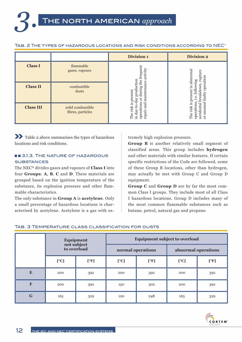
Table 2 above summarises the types of hazardous locations and risk conditions.
3.1.3. The nature of hazardous substancesThe NEC® divides gases and vapours of Class I into four Groups: A, B, C and D. These materials are grouped based on the ignition temperature of the substance, its explosion pressure and other flam-mable characteristics.The only substance in Group A is acetylene. Only a small percentage of hazardous locations is char-acterised by acetylene. Acetylene is a gas with ex-
tremely high explosion pressure.Group B is another relatively small segment of classified areas. This group includes hydrogen and other materials with similar features. If certain specific restrictions of the Code are followed, some of these Group B locations, other than hydrogen, may actually be met with Group C and Group D equipment.Group C and Group D are by far the most com-mon Class I groups. They include most of all Class I hazardous locations. Group D includes many of the most common flammable substances such as butane, petrol, natural gas and propane.
Tab. 2 The types of hazardous locations and risk conditions according to NEC®
Division 1 Division 2
Class I flammable gases, vapours
Class II combustible dusts
Class III solid combustible fibres, particles
The
risk
is p
rese
nt
in d
ay-t
o-da
y pr
oduc
tion
op
erat
ions
or
duri
ng th
e fr
eque
nt
repa
ir a
nd m
aint
enan
ce a
ctiv
ity
The
risk
is p
rese
nt in
abn
orm
al
oper
atio
ns, i
.e. f
ollo
win
g ac
cide
ntal
bre
akdo
wn,
rup
ture
or
unu
sual
faul
ty o
pera
tion
[°C] [°F] [°C] [°F] [°C] [°F]
E 200 392 200 392 200 392
F 200 392 150 302 200 392
G 165 329 120 248 165 329
Tab. 3 Temperature class classification for dusts
Equipment subject to overload
normal operations abnormal operations
Equipment not subject to overload
The north american approach3.

13 the iec and nec® certification systems
Class I, gases and vapours, is divided into
Groups A, B, C and D, whereas Class II, dusts, into Groups
E, F and G.
In Class II – locations for the presence of dust – hazardous materials are divided into Groups E, F and G. These groups are classified based on ignition temperature and conductivity of the hazardous substances. Conductivity is an im-portant issue in Class II locations, in particular metal dusts.Metal dusts are classified in the Code as Group E: it includes alu-minium and magnesium and other metal dusts of similar nature.Group F contains materials such as carbon black, wood coal dust, pieces of coal and hard coal dust.Group G includes cereal, flour, starch, cocoa dust and other types of materials.Table 3 on the previous page shows the classification of temperature classes for dusts.
3.1.4. ReviewLet's quickly review what we have seen so far. Hazardous locations are classified in three ways by the National Electrical Code®: type, status and nature.There are three types of danger conditions: Class I – gas and vapours, Class II – dust Class III –
combustible fibres and solid par-ticles.There are two types of danger con-ditions: Division 1 – normal, Di-vision 2 – abnormal.Finally, there is the nature of the hazardous substances which in-cludes Groups A, B, C and D in Class I locations and Groups E, F and G in Class II locations.Table 4 summarises the various classified hazardous locations.
Tab. 4 Class I, II, III hazardous locations
CLASS GROUPS
Igases, vapours
and liquids(art. 501)
A: acetyleneB: hydrogen, etc.C: ether, etc.D: hydrocarbons, fuels, solvents, etc.
normally present and hazardous explosive atmosphere
atmosphere normally not present in an explosive concentration (but may be accidentally present)
IIdusts
(art. 502)
E: metallic dusts (conductive* and explosive)F: coal dusts (some are conductive* and all are explosive)G: flour, starch, wheat, combustible plastic or chemical powder (explosive)
flammable amounts of dust are or may be normally in suspension (cloud), or conductive dusts may be present
dust normally not suspended (cloud) in a flammable concentration (but may accidentally exist). Layers of dust are present.
IIIsolid combustible
fibres and particles(art. 503)
textile products, wood processing, etc. (easily flammable, but does not risk being explosive)
handled or used in production stored or handled in warehouse (excluding production)
DIVISION
*NOTE: electrically conductive dusts are dusts with resistivity less than 105 Ω/cm.
1 2
The north american approach3.

the iec and nec® certification systems 14
4.The europeanand international approach
4.1. Analysis of the european and international approach
4.1.1. Types of hazardous locationsa) Classification of locations due to gas presence.On the technical-regulatory level, the locations where there are or may be explosive atmospheres due to the presence of gases in such quantities as to require special precautions for the construction, installation and use of equipment, are those which for the longest time have been regulated technically as well as in terms of legisla-tion by individual States.Explosive atmospheres for the presence of gas consid-er flammable substances in gas or vapour form, mixed with air, in atmospheric conditions.There is no definite list of locations to be taken into ac-count, but there are more than we can imagine! 328 Combustible gases are classified in standard IEC 60079-20-1. Reasoning in terms of macro areas, we might say that we should make the classification in the following locations:
refineries
chemical industry
energy production
painting
O n the level of technical standards, the Euro-pean and international approach match since most standards are voted with "pa-
rallel vote procedure": the European members of the vari-ous national Committees vote the document for it to si-multaneously become international as well as European standard. This procedure is also valid for the Ex standard sphere. The following regulatory framework applies:1 . Location classification- IEC 60079-10-1: 2008-12 “Explosive atmospheres – Part 10-1: Location classification. Explosive atmos-pheres due to the presence of gas".- IEC 60079-10-2: 2009-04 “Explosive atmospheres – Part 10-2: Location classification. Explosive atmos-pheres due to the presence of combustible dusts".2. Choice and installation of equipment- IEC 60079-14: 2007-12 “Explosive atmospheres – Part 14: Design, choice and installation of electrical sys-tems".
Regulatory framework:IEC 60079-10-1:2008-12 IEC 60079-10-2:2009-04 IEC 60079-14:2007-12

15 the iec and nec® certification systems
DU
ST
S
GA
SE
S4. The european and international approach
pharmaceutical industry
recycling
landfills
gas supply
b) Classification of locations according to the presence of combustible dusts.The locations where there are or may be explosive at-mospheres due to the presence of combustible dusts or solid particles, in such an amount as to require spe-cial provisions for construction, installation and use of equipment, are decidedly more recent than those of gases: in fact they are dated 2002.Also in this case there is no definitive list to be consid-ered, but there are more than we can imagine! If there are 328 classified combustible gases, the BIA report 13/97 mentions more than 4,300 combustible dusts,
to include sawdust, flour and bread crumbs! And even more have been classified since 1997!Reasoning in terms of macro areas, we might say that we should make the classification in the following locations:
wood industry
food and feed industry
metal and plastics industry
pharmaceutical industry
4.1.2. The conditions of hazardous locationsThe European and international standards mentioned above classify hazardous locations in Zones based on the frequency of formation and permanence of an explo-sive atmosphere caused by the presence of gas or com-bustible dusts (Fig. 4).
Zone 0 Zone 1 Zone 2
Zone 20 Zone 21 Zone 22
Note: the graphical lines in each box are internationally standardised ones
Fig.4 The division of hazardous locations based on the presence and concentration of gases (Zone 0, 1 and 2) and dusts (Zone 20, 21 and 22)

16 the iec and nec® certification systems
It should be noted that, with regards to com-bustible dusts, the division into zones is exclusively determined by dust in the form of cloud; the layers, deposits and accumulations of dust are considered as "any other source" that might form an explosive atmosphere from dust, but do not determine any zone.We would like to underline that also in its latest re-port of 2011 the UN agency UNECE (http://www.unece.org/) refers to international IEC standards as an instrument to be implemented for the division of hazardous locations into zones.Finally, with regards to the European Union, the "Social Directives" block, i.e. those standards that set forth requirements for improving workers' pro-tection and safety, includes Directive 99/92/EC, known as “ATEX 137” (Tab. 5) (due to the Treaty's article) or more simply as the second “ATEX” Direc-tive. This document is the legal reference for em-ployers of those workers who might be exposed to the hazard of explosive atmospheres.But where is the difference between the various zones? The difference lies in the likelihood of the
explosive atmosphere of reference - within the explosiveness range - being present for a certain length of time over one year (Tab. 6).
Tab. 5 The “ATEX 137” directive
“A
TE
X 1
37”
htt
p:/
/ec.
euro
pa.
eu/s
ocia
l
Directive 1999/92/EC of the European Parliament and Council, of 16 December 1999 “Minimum requirements for improving the protection of the safety and health of workers potentially at risk from explosive atmospheres” (XV special Directive pursuant to article 16, paragraph 1 of directive 89/391/EEC)
(EC.O.J. series L, no. 23 of 28 January 2000)
Tab. 6 The classification of hazardous zones due to the presence of gas and dusts according to international standards (IEC Zone System)
Zone 0 / Zone 20 Zone 1 / Zona 21 Zone 2 / Zone 22
D
US
TS
G
AS
ES
Location where an explosive atmosphere caused by the presence of gas (Zone 0) or of dust in cloud form (Zone 20) or for long periods or frequently
Location where an explosive atmosphere caused by the presence of gas (Zone 1) or dust in cloud form (Zone 21) is likely to be occasionally present during normal operation
Location where an explosive atmosphere caused by the presence of gas (Zone 2) or dust in cloud form (Zone 22) is not likely to be present during normal operation, but should this occur, it is likely to persist for short periods only
4. The european and international approach

17 the iec and nec® certification systems
4.1.3. The nature of hazardous substancesa) Combustible gases.With regards to combustible gases, they are divided into two Groups (“I” and “II”) and Group II is divided into three sub-groups: A, B and C.This subdivision is based on the maximum safety experimental gap (MESG) or on the minimum ignition current ratio (MIC ratio) of the ex-plosive atmosphere due to the pres-ence of gas where the equipment may be installed.Application of this concept has resulted in the division represented in Graph 1.Among all these gases, some representative ones of their group or sub-groups have been identified (Tab. 7).b) Combustible dusts.With regards to combustible dusts, they have recently been inserted in a new group (Group “III”) and divided into three sub-groups: A, B and C:
- IIIA: combustible particles, i.e.“solid particles, in-
cluding fibres, of nominal dimen-sions> 500 μm”;- IIIB: non-conductive dust, i.e.“solid particles finely subdivided, of nomi-nal dimensions ≤ 500 μm, with elec-trical resistivity > 103 Ωm”;- IIIC: conductive dust, i.e.“solid par-ticles finely subdivided, of nominal dimensions ≤ 500 μm, with electrical resistivity ≤ 103 Ωm”.Group III has been defined on the technical product standard (IEC 60079-0), on the classification one
(IEC 60079-10-2), and on the installation one (IEC 60079-14).
4.1.4. ReviewLet's quickly review what we have dealt with in this chapter.There are two types of hazardous conditions: those caused by gases, vapours, clouds, and those caused by combustible dusts.There are three types of danger conditions: Zone
227 IIA
66 IIB
5 IIC
28 undetermined 1 I
Graph 1 The subdivision of gases into sub-groups
Group Sub-group Gas GAS No.
I firedamp (methane)
74-82-8
IIA propane 74-98-6
IIB ethylene 74-85-1
hydrogen 1333-74-0
acetylene 74-86-2
Tab. 7 Some of the most representative gases
IIC
II
227combustible gases belong to group IIA, 66 to group
IIB
4. The european and international approach

18 the iec and nec® certification systems
0 or 20 – very high risk, Zone 1 or 21 – high risk, Zone 2 or 22 – normal risk.And finally, there is the nature of the hazardous sub-stance: Group I, that regards the presence of firedamp and pulverised coal (normally defined as “mine”), Group II and Group III both divided into A, B and C.
Table 8 summarises the various classified hazardous lo-cations.
The contents of this paragraph 4 also ap-plies to the National Electrical Code, art. 505 and 506.
Tab. 8 Summary chart of the classified hazardous locations
DU
ST
S
G
AS
ES
GROUPS
I: firedamp
IIA: propane
IIB: ethylene
IIC: hydrogen and acetylene
0 1 2ZONES
IIIA: combustible
particles
IIIB:non-conductive
dust
IIIC:non-conductive
dust
20 21 22
The explosive atmosphere is present continuously or for long periods or frequently
The explosive atmosphere is likely to be occasionally present during normal operation
The explosive atmosphere is not likely to be present during normal operation, but should this occur, it is likely to persist for short periods only
4. The european and international approach
the iec and nec® certification systems 19
A s we have seen, problems never end. A potentially explosive mixture consist-ing of combustible gas and air does not
behave differently according to where it is; if ignition conditions are favourable, the explosion risk becomes tangible.The methods we have presented have been defined by different subjects in order to reduce the initial risk.
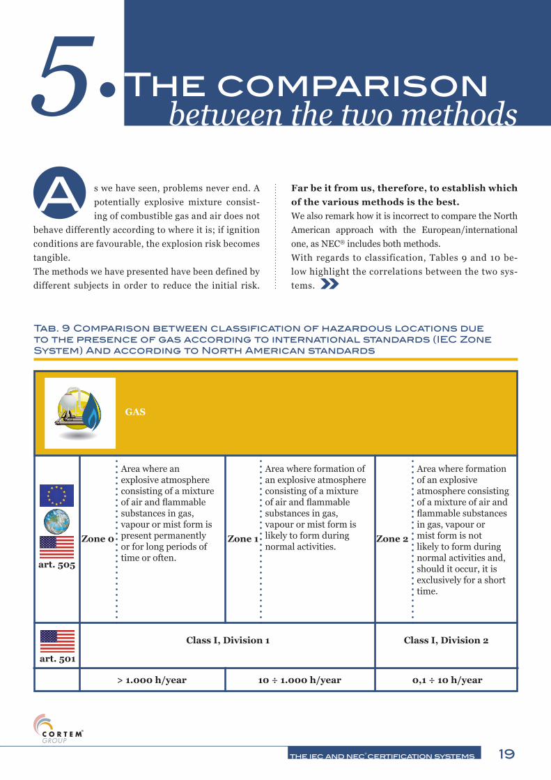
Far be it from us, therefore, to establish which of the various methods is the best.We also remark how it is incorrect to compare the North American approach with the European/international one, as NEC® includes both methods.With regards to classification, Tables 9 and 10 be-low highlight the correlations between the two sys-tems.
between the two methods5.The comparison
Tab. 9 Comparison between classification of hazardous locations due to the presence of gas according to international standards (IEC Zone System) And according to North American standards
Area where an explosive atmosphere consisting of a mixture of air and flammable substances in gas, vapour or mist form is present permanently or for long periods of time or often.
Area where formation of an explosive atmosphere consisting of a mixture of air and flammable substances in gas, vapour or mist form is likely to form during normal activities.
Area where formation of an explosive atmosphere consisting of a mixture of air and flammable substances in gas, vapour or mist form is not likely to form during normal activities and, should it occur, it is exclusively for a short time.
Class I, Division 1 Class I, Division 2
> 1.000 h/year 10 ÷ 1.000 h/year 0,1 ÷ 10 h/year
Zone 0 Zone 1 Zone 2
art. 505
art. 501
GAS

20 the iec and nec® certification systems
The comparison between the two methods 5.Tab. 10 Comparison between the classification of hazardous locations due to the presence of dusts according to international standards (IEC Zone System) and according to North American standards
Area where an explosive atmosphere in the form of combustible dust cloud in the air is present permanently or for long periods or often.
Area where an explosive atmosphere in the form of combustible dust cloud in the air is occasionally likely to form during normal activities.
Area where an explosive atmosphere in the form of combustible dust cloud is not likely to form during normal activities and, should it occur, it is only for a short time.
Class II, Division 1 Class II, Division 2
> 1.000 h/year 10 ÷ 1.000 h/year 0,1 ÷ 10 h/year
Zone 20
Zone 21
Zone 22
art. 505
art. 502
DUSTS
propane IIA D
ethylene IIB C
hydrogen B
acetylene AIIC
art. 505 art. 501
Tab. 11 The subdivision of gases
With regards to gas subdivision, the greatest dif-ference lies in the attribution of the order of letters, as shown in Table 11.With regards to dusts, it is difficult to draw a com-parison since the classification criteria of each meth-od are different.Table 12 describes the comparison between classes of temperature since art. 500 of NEC® entails in-termediate ones between those used by the other method.Furthermore, the two systems have different “nor-mal” ambient temperatures (Tab. 13).As required by the technical standards, each prod-uct is placed on the market with its own identifi-cation plate which contains some information. Let us compare an identification plate complying with European/international standards with one com-

21 the iec and nec® certification systems
plying with art. 500 of NEC® (Fig. 5 and 6 on the following page).The identification plate complying with European/international standards (Fig. 5) includes:- the name or logo of the manufacturer, i.e. the en-tity responsible for placing the product on the mar-ket; - the year of manufacture 1 , the serial number 2 , equipment identification by means of product
code definition 3 ; - equipment data: temperature class 4 , maximum surface temperature 5 , ambient temperature 6 , electrical data as per certificate 7 ; - data concerning Ex aspects, i.e. marking, certifi-cate number, etc. 8 ; - warnings. The identification plate complying with art. 500 NEC® includes:- equipment identification through product code definition 1 ;- type of protection 2 and serial number 3 ;- the name or logo of the manufacturer, i.e. the en-tity responsible for placing the product on the mar-ket 4 ;
Tab. 12 Comparing European/international and North American classes of temperature for Group II
[°C] [°F]
450 842
300 572
280 536 T2A
260 500 T2B
230 446 T2C
215 419 T2D
200 392
180 356 T3A
165 329 T3B
160 320 T3C
135 275
120 248 T4A
100 212
85 185T6
table 505.9(d)(1)
table 500.8(c)
T5
T4
T3
T2
T1
-20 ÷ +40 [°C] -25 ÷ +40 [°C]
art. 505 art. 500
Tab.13 Comparison between European/international and North American “normal” ambient temperatures
-25 ÷ +40 [°C] is the "normal" ambient temperature set forth by art. 500 of NEC®
The comparison between the two methods 5.

22 the iec and nec® certification systems
Fig. 5 identification plate complying with European/international standards
Ex d IIC T4
Ex tb IIIC T130°C
Gb
Db IP66
Ex d IIC T4
Ex tb IIIC T130°C
Gb
Db IP66
art. 505
Class I Zone 1 AEx d IIC T4 Gb
art. 506
Zone 21 AEx tb IIIC T130°C Db IP66
art. 500
Class I Division 1
Class II Division 1
Groups A, B, C, D, T4
Groups E, F, G, T4
Tab. 14 How the equipment marking changes in the various
9876 II 2G
II 2D
- equipment marking 5 ;- the certificate number 6 ;- warnings and logo of the notified body, such as, in this
case, Underwriters Laboratories (UL).Finally, we deem it useful to see how the marking of the same equipment might change in the different systems (Tab. 14).
Fig. 6 Identification plate complying with art. 500 of NEC
The comparison between the two methods 5.

the iec and nec® certification systems 23
C onformity assessment, be it of products, processes or services, is quite similar in the various parts of the world and is
based on the trust the “certifier” is able to inspire in the concerned parties (manufacturers, users, Authorities, etc.) through impartiality, competency and confidenti-ality of its operations.In the following table (Tab. 15) we have set out the three entities we deal with and which "qualify" conformity as-sessment bodies to perform their task at the end of a pathway.It should be noted that little more than ten years ago IEC created its own certification scheme dedicated to the “Ex” sector which, as well as certifying products, also certifies persons' skills.Table 16 on the next page summarises regulatory agen-cies and the number of bodies assessing conformity of products in general and Ex ones.The last table highlights numbers that it is likely we have never taken into consideration because of a certain tradition.Although all these schemes call for the products to meet industrial standards before “Ex” ones (see graph 2 in the next paragraph), and for the manufacturer to keep under control both the design and the production stage
in order to be able to place the product on the market, there is a substantial difference between the various systems on the control of the latter stage.Both the EC “ATEX” Directive and the IECEx certifica-tion scheme entail the possibility that a different
certification6.The product
• Ministry of Labour
• Occupational Safety and Health Administration (OSHA)
• Nationally Recognized Testing Laboratory (NRTL)
• European Union
• European Commission
• New Approach Notified and Designated Organisations (NANDO)
• International Electrotechnical Commission
• IEC System of Conformity Assessment Schemes for Electrotechnical Equipment and Components (IECEE)
Tab. 15 Regulatory agencies divided by territorial competence
Fig. 7 ATEX Certification of production quality

24 the iec and nec® certification systems
The product certification 6.
Body from the one that issued the project certifi-cate might oversee the manufacture of the product. Fur-thermore, the custom is for the overseeing action to be carried out with yearly frequency (the interval between one audit and the next one is about 12 months). Accord-ing to the US scheme, however, manufacturing is over-
seen by the same body that issued the project certificate and frequency is four times a year. Therefore, in the event a manufacturer should have several project cer-tificates with various bodies, they will receive as many audits (4 a year) as the number of bodies from which they have obtained the project certificates.
• Nationally Recognized Testing Laboratory (NRTL)
• New Approach Notified and Designated Organisations (NANDO)
• IEC system for certification to standards relating to equipment for use in explosive atmospheres (IECEx system)
No. of conformity assessment bodies:
No. of Ex sector conformity assessment bodies:
15
8
1.564
69 48
Tab. 16 Number of conformity assessment bodies and number of Ex sector conformity assessment bodies overseen by regulatory bodies
19/11/14 16:25FTRV.E468486 - Enclosures for Use in Hazardous Locations
Pagina 1 di 1http://database.ul.com/cgi-bin/XYV/template/LISEXT/1FRAME/show…1073741824&version=versionless&parent_id=1073986881&sequence=1
FTRV.E468486Enclosures for Use in Hazardous Locations
Page Bottom
Enclosures for Use in Hazardous Locations
See General Information for Enclosures for Use in Hazardous Locations
CORTEM S P A E468486VIA AQUILEIA 1034070 VILLESSE, (GO) ITALY
Class I, Groups C and D; Class II, Groups E, F and G.
Series SX9 GUB, Cat. No. SX9GUB may be followed by -D, -DW or -W, followed by -1, -2 or -3, may be followed by A, followed by -1, -2, -3, -4,-10, -12, -16, -17, -27 or -35, followed by -1, -2, -3, -4, -5, -6, -7, -8, -9 and/or -10.
Series SXE, Cat. No. SXE, followed by -1/2 or -3.
Series SX7E, Cat. No. SX7E, followed by -FC6, -GC6, -GC8, -GE9, -GF6, -GG6, -IC8, -IIC, -KK8, -OCC, -OF6, -SG8, -SGD and -XCD.
Series SX7E enclosures, Cat. Nos. SX7E-644, -664, -666, -864, -866, -883, -884, -888, -A66, -AA6, -C56 for use in Class I, Groups C and D;Class II, Groups E, F and G Hazardous Locations. Conduit sizes 1/2 through 4 in. NPT.
Last Updated on 2014-05-21
Questions? Print this page Terms of Use Page Top
© 2014 UL LLC
When the UL Leaf Mark is on the product, or when the word "Environment" is included in the UL Mark, please search the UL Environmentdatabase for additional information regarding this product's certification.
The appearance of a company's name or product in this database does not in itself assure that products so identified have been manufacturedunder UL's Follow-Up Service. Only those products bearing the UL Mark should be considered to be Certified and covered under UL's Follow-UpService. Always look for the Mark on the product.
UL permits the reproduction of the material contained in the Online Certification Directory subject to the following conditions: 1. The GuideInformation, Assemblies, Constructions, Designs, Systems, and/or Certifications (files) must be presented in their entirety and in a non-misleading manner, without any manipulation of the data (or drawings). 2. The statement "Reprinted from the Online Certifications Directorywith permission from UL" must appear adjacent to the extracted material. In addition, the reprinted material must include a copyright notice inthe following format: "© 2014 UL LLC".
Fig. 8 Example of IECEx certificate Fig. 9 Example of UL certificate

the iec and nec® certification systems 25
T o go back to what has been introduced in the previous paragraph, products tend to be subdivided by the market and by
manufacturers based on the intended use, as shown in the following graph (Graph 2).This implies that “Ex” products are a “whereof” and therefore must first meet industrial regulations and then, in addition, specific “Ex” ones.Table 17 shows the main Ex standards for each certifica-tion scheme (for practical reasons we exclusively show the standards whose protection method is applicable to different types of equipment) used for certification pur-poses.Finally, in Table 18 we deem it useful to indicate some “Ex” standards that are specific for a certain family of products.
supporting certification 7. The standards
Graph 2 product subdivision based on intended use
suddivisione dei prodotti in base alla destinazione d’uso
Product subdivision basedon intended use
Household
ProfeSsional
Industrial and retail
Ex

26 the iec and nec® certification systems
The standards supporting certification 7.
art. 502 art. 505
General rules
ANSI/ISA 60079-0
UL 60079-0EN 60079-0 IEC 60079-0
Flame-proof enclosures – “d”
UL 1203
Pressurised equipment– “p”
NFPA 496 ANSI/ISA 61241-2 EN 61241-4 IEC 61241-4
Equipment with intrinsic safety – “i” UL 913
ANSI/ISA 60079-11
UL 60079-11EN 60079-11 IEC 60079-11
Equipment with protection mode “n” ISA 12.12.01
Encapsulated equipment – “m”
ANSI/ISA 60079-18
UL 60079-18EN 60079-18 IEC 60079-18
Equipment protected by enclosures – “t”
FM 3616 ANSI/ISA 60079-31 EN 60079-31 IEC 60079-31
PO
LV
ER
I
Tab. 17 Main Ex standards for gases and dusts used for certification purposes
art. 501 art. 505
General rules FM 3600
ANSI/ISA 60079-0
UL 60079-0EN 60079-0 IEC 60079-0
Flame-proof enclosures – “d”
FM 3615
UL 1203
ANSI/ISA 60079-1
UL 60079-1EN 60079-1 IEC 60079-1
Pressurised equipment– “p”
ANSI/ISA 12.04.04FM 3620
NFPA 496
ANSI/ISA 60079-2
EN 60079-2 IEC 60079-2
Filling equipment – “q”
ANSI/ISA 60079-5
UL 60079-5EN 60079-5 IEC 60079-5
Equipment immersed in oil – “o”
ANSI/ISA 60079-6
UL 60079-6EN 60079-6 IEC 60079-6
Equipment with enhanced safety – “e”
ANSI/ISA 60079-7
UL 60079-7EN 60079-7 IEC 60079-7
Equipment with intrinsic safety – “i”
FM 3610
UL 913
ANSI/ISA 60079-11
UL 60079-11EN 60079-11 IEC 60079-11
Equipment with protection mode “n”
ANSI/ISA 12.12.01
FM 3611
ANSI/ISA 60079-15
UL 60079-15EN 60079-15 IEC 60079-15
Encapsulated equipment – “m”
ANSI/ISA 60079-18
UL 60079-18EN 60079-18 IEC 60079-18
systems with intrinsic safety – “i” ANSI/ISA 60079-25 EN 60079-25 IEC 60079-25
Equipment with optical radiation – “op” ANSI/ISA-TR 12.21.01 ANSI/ISA 60079-28 EN 60079-28 IEC 60079-28
Equipment with special protection – “s” IEC 60079-33
GA
S

27 the iec and nec® certification systems
Table 18 Specific EX standards for certain families of products
art. 501 art. 505
Portable electronic products ANSI/ISA 12.12.03
Land mobile radios FM 3640
Submersible electric motors FM 3650
Electric motors and generators UL 674
Industrial control panels UL 698A
Electrical torches and lanterns
FM 3613
UL 783
Electrical heaters
FM 7320
UL 823
Lighting fixtures UL 844
Cables and accessories for cables UL 2225
Explosion venting devices FM 7730 EN 14797
Industrial trucks EN 1755
Alternative internal combustion engines ANSI/ISA 12.20.01 EN 1834
Service stations
EN 13012
EN 13617
Non-electrical equipment EN 13463
Suppression systems EN 14373
Fans EN 14983
Transportable vented booths EN 50381
Pressurised premises – “p” EN 60079-13 IEC 60079-13
Gas detectors ANSI/ISA 60079-29 EN 60079-29 IEC 60079-29
The standards supporting certification 7.

the iec and nec® certification systems
CORTEM GROUPTo be sure to be safe
Since 1968 Cortem S.p.A. has been designing and manufacturing protected electrical equipment intended for installation in areas at risk of explosion and fire. Thanks to constant technological innovation and continuous improvement, today it is a leading company in the industry, able to offer a wide range of solutions suitable for on-shore and off-shore applications. The special feature of Cortem Group - which includes the Cortem, Elfit e Fondisonzo brands - consists in its long-standing experience accrued in the sector, resulting in the ability to not merely supply Ex products, but custom-made solutions as well.All of our products are designed and manufactured in-house with various protection methods such as ‘Ex d’ explosion proof, ‘Ex e’ enhanced safety, ‘Ex de’ mixed, ‘Ex n’ no sparking, using aluminium alloy, stainless steel and top quality plastics materials. The aluminium alloy used by Cortem has exceeded the tests required by standards EN60068-2-30 (hot/humid cycles) and EN60068-2-11 (salt mist tests). All our aluminium alloy products are protected by RAL 7035 epoxy coating. This treatment is a Cortem Group exclusive and assures long-term protection.Cortem Group's production may be summarised as follows:• Lighting fixtures, lighting fixtures for signalling obstacles, floodlights and portable lamps.• Junction and pulling boxes, control stations.• Signalling and control equipment, sockets and plugs.• Cable glands and fittings.• Special designs: electrical panels and control batteries based on the customer's requirements.90% of our production is intended for the Oil & Gas sector, both off-shore and on-shore, but also chemical and pharmaceutical industries, as well as all those process areas characterised by the presence of explosive atmospheres such as grain silos, wood mills and paper mills. Every year we invest part of our resources in developing innovative products to address the market's needs. That is why our R&D department devises the best solutions considering regulatory, installation, safety and market price aspects.With over 30 agencies, 90 distributors, 7 partners and 3 de-centralised production facilities, Cortem assures a qualified local presence in the world. For Cortem “de-localising” does not mean transferring plants, means, know-how and resources to low-cost Countries, but rather replicating a winning model of industrial organisation where environmental safety, product quality, compliance with standards, technical support and market after-sale support are the foundations of our Corporate Mission.The Pay Off “to be sure to be safe” represents the pride and passion for what we design and produce.

the iec and nec® certification systems
Certification systemsIEC E NEC®
Ed. December 2014
CopyrightUnder the law on copyright, the Italian Civil Code and other provisions in force in markets where CortemGroup operates, any information, image, photograph, drawing, table or anything else contained in CortemGroup's illustrative/promotional material is exclusive property of CortemGroup, which holds any moral and economic and commercial exploitation rights. Any reproduction with any means either fully or in part of Cortem-Group's illustrative/promotional material is therefore forbidden without explicit written authorisation by Cortem Group. Any breach of the above shall be persecuted pursuant to law. ©di Cortem- Villesse - Italia. All rights reserved

the iec and nec® certification systems
Sales DepartmentPiazzale Dateo 220129 Milano, Italy
Italytel. +39 02 76 1103 29 r.a.fax +39 02 73 83 [email protected]
Exporttel. +39 02 76 1105 01 r.a.fax +39 02 70 00 54 [email protected]@cortemgroup.com
Registered Office and Production FacilityVia Aquileia 10, 34070 Villesse (GO), Italytel. +39 0481 964911 r.a.fax +39 0481 [email protected]
Registered Office and Production FacilityVia Aquileia 12, 34070 Villesse (GO), Italytel. +39 0481 91100fax +39 0481 [email protected]
Sales DepartmentPiazzale Dateo 220129 Milano, Italy
Italytel. +39 02 76 1103 29 r.a.fax +39 02 73 83 [email protected]
Exporttel. +39 02 76 1105 01 r.a.fax +39 02 70 00 54 [email protected]@cortemgroup.com
Registered Office and Production FacilityVia Aquileia 10, 34070 Villesse (GO), Italytel. +39 0481 964911 r.a.fax +39 0481 [email protected]
IEC
and
NEC
® ce
rtifi
catio
n sy
stem
s 12
/201
4 - K
....
Gra
phic
des
ign
and
layo
utRa
ffael
la S
esia