the application of unmanned aerial systems in surface
TRANSCRIPT

The Application of Unmanned Aerial Systems In Surface
Transportation - Volume II-A: Development of a Pilot Program to
Integrate UAS Technology to Bridge and Rail Inspections
Charles D. Baker Governor
Karyn E. Polito Lieutenant Governor
Stephanie Pollack MassDOT Secretary & CEO
December 2019 Report No. 19-010
Principal Investigator(s)Dr. Daiheng Ni
Dr. Michael Plotnikov University of Massachusetts Amherst
Research and Technology Transfer Section
MassDOT Office of Transportation Planning

i
Technical Report Document Page
1. Report No.19-010
2. Government Accession No.n/a
3. Recipient's Catalog No.n/a
4. Title and SubtitleThe Application of Unmanned Aerial Systems In SurfaceTransportation - Volume II-A: Development of a PilotProgram to Integrate UAS Technology to Bridge and RailInspections
5. Report DateDecember 20196. Performing Organization Code19-010
7. Author(s)Michael Plotnikov, Daiheng Ni, David Price
8. Performing Organization Report No.
9. Performing Organization Name and AddressUniversity of Massachusetts AmherstUMass Transportation Center, 214 Marston Hall130 Natural Resources Road, Amherst, MA 01003
10. Work Unit No. (TRAIS)n/a11. Contract or Grant No.
12. Sponsoring Agency Name and AddressMassachusetts Department of TransportationOffice of Transportation PlanningTen Park Plaza, Suite 4150, Boston, MA 02116
13. Type of Report and Period CoveredFinal ReportApril 2018 – December 201914. Sponsoring Agency Coden/a
15. Supplementary NotesProject Champion – Jeffrey DeCarlo, MassDOT Aeronautics Division16. AbstractCentral to the conduct of this research was a review of current procedures used in State DOTbridge and rail inspections and the experiences of these State DOTs in integrating UAStechnologies into such inspections. Based on this review, the UMass research team developedand tested practical procedures and protocols to guide MassDOT in the integration of UAStechnologies into bridge and rail inspections It was determined that the major factors that affectthe success of UAS integration into the bridge and rail inspections relate to the selection of theproper types of UAS platforms and sensors. It is recommended that a rotorcraft UAS platform beused for the majority of bridge inspections and fixed wing platform for general surveys ofextended areas, such as railroad right-of-way. Depending on the type and purpose of theinspection, thermal and LiDAR imaging cameras were found to be the most useful sensortechnologies.17. Key Wordsunmanned aircraft system, UAS, drone, surfacetransportation, bridge inspection, rail inspection,inspection procedures, asset management
18. Distribution Statementunrestricted
19. Security Classif. (of this report)unclassified
20. Security Classif. (of this page)unclassified
21. No. ofPages73
22. Pricen/a
Form DOT F 1700.7 (8-72) Reproduction of completed page authorized

ii
This page left blank intentionally.

iii
The Application of Unmanned Aerial Systems In Surface Transportation - Volume II-A:
Development of a Pilot Program to Integrate UAS Technology to Bridge and Rail Inspections
Prepared By:
Michael Plotnikov,Ph.D. Principal Co-Investigators
Daiheng Ni, Ph.D. Principal Co-Investigators
Other Contributors David Price
Christopher Lyman
University of Massachusetts Amherst 130 Natural Resources Road
Amherst, MA 01003
Prepared For: Massachusetts Department of Transportation
Office of Transportation Planning Ten Park Plaza, Suite 4150
Boston, MA 02116
December 2019

iv
This page left blank intentionally.

v
Acknowledgements
This study was undertaken as part of the Massachusetts Department of Transportation Research Program with funding from the Federal Highway Administration State Planning and Research funds. The authors are solely responsible for the accuracy of the facts and data, the validity of the study, and the views presented herein.
The research team would like to acknowledge the efforts of Dr. Jeffrey DeCarlo from the MassDOT Aeronautics Division for his help and guidance throughout all stages of the project and the help of his team as well. In addition, the research team would like to acknowledge the contribution of Gabriel Sherman and Jose Simo from MassDOT’s Office of Transportation Planning Research Section for providing the research team with valuable feedback from MassDOT during the study. We would also like to thank John Collura, Matt Mann, and Tracy Zafian from the UMass Transportation Center for their contributions to interagency coordination and their review of the project’s draft reports.
Disclaimer
The contents of this report reflect the views of the authors, who are responsible for the facts and the accuracy of the data presented herein. The contents do not necessarily reflect the official view or policies of the Massachusetts Department of Transportation or the Federal Highway Administration. This report does not constitute a standard, specification, or regulation.

vi
This page left blank intentionally.

vii
Executive Summary
This study entitled, Development of a Pilot Program to Integrate UAS Technology into Bridge and Rail Inspections, was conducted as part of the Massachusetts Department of Transportation (MassDOT) Research Program. This program is funded with Federal Highway Administration (FHWA) State Planning and Research (SPR) funds. Through this program, applied research is conducted on topics of importance to the Commonwealth of Massachusetts transportation agencies. The study included four subtasks:
1. Conduct a literature review of standard bridge and rail inspection procedures and protocols carried out by state DOTs.
2. Review the experiences and challenges associated with integrating UAS into the inspection procedures and protocols, and with other data collected during inspections.
3. Develop practical procedures and protocols for MassDOT for using UAS in bridge and rail inspections.
4. Test these UAS based procedures and protocols in collaboration with MassDOT staff. Based on the results of sub-tasks 1 and 2, the UMass research team concluded that UAS can serve as a useful tool for MassDOT in a majority of bridge and rail inspection procedures, with the exception of in-depth bridge inspections, because these types of inspections require hands-on testing. The major factors that affect the success of UAS integration into these inspections relate to selection of the proper types of UAS platforms and sensors. It is recommended that a rotorcraft UAS platform be used for the majority of bridge inspections and fixed wing platform for general surveys of extended areas, such as railroad right-of-way. The most useful sensors for bridge inspections include thermal sensors to detect areas of bridge deck delamination and high-zoom visual spectrum cameras to facilitate the close-up inspection of joints, bolts, and welds and to identify delineations like stress cracks in the steel structures, bridge decks and other elements. Also, LiDAR sensors are recommended for asset management to provide high definition measurements of transportation infrastructure; to conduct right-of-way surveys; to create 3D models; and to detect the presence of transportation infrastructure elements such as bridges, light poles, and signs. UAS can also be implemented to assist with rail bridge inspections, construction, and general maintenance and right-of-way inspections. However, because of the current FRA regulations, UAS cannot be used for the annual routine inspection of railroad tracks. The results of sub-task 3 and Section 4.0 included the development of practical procedures and protocols for MassDOT to integrate the use of UASs into future bridge and rail inspections. The procedures and protocols have taken into consideration the major issues, challenges, practices, and lessons learned from existing UAS based practices, including the UAS data collection, storage, and dissemination. The procedures and protocols were developed with MassDOT’s specific needs and organizational constraints in mind and efforts were made to ensure that any new procedures and checklists developed specifically for bridge or rail inspections conform to existing policies and procedures at MassDOT.

viii
This page left blank intentionally.

ix
Table of Contents
Technical Report Document Page ............................................................................................. i Acknowledgements ....................................................................................................................v Disclaimer ..................................................................................................................................v Executive Summary ................................................................................................................ vii Table of Contents ..................................................................................................................... ix List of Tables ........................................................................................................................... xi List of Figures ........................................................................................................................ xiii List of Acronyms .....................................................................................................................xv 1.0 Introduction ..........................................................................................................................1
1.1 Problem Statement ....................................................................................................................... 1 1.2 Research Objectives ..................................................................................................................... 1 1.3 Report Outline .............................................................................................................................. 1
2.0 Research Methodology ........................................................................................................3 3.0 Results ..................................................................................................................................5
3.1 Literature Review of Procedures and Protocols for Bridge and Rail Inspections ........................ 5 3.1.1 An Overview of the Current Highway Bridge Inspection Procedures .................................. 5 3.1.2 An Overview of the Current Rail Inspection Procedures ..................................................... 7
3.2 Exploring Challenges with Integrating Data from UAS Inspections ......................................... 11 3.2.1 Summary of Experiences Associated with UAS Integration into Highway Bridge Inspection ..................................................................................................................................... 16 3.2.2 Summary of Experiences Associated with UAS Integration into Rail Inspections ............ 17 3.2.3 Examples of Use of UAS for Rail and Bridge Inspections ................................................. 18
3.3 Developing Practical Procedures and Protocols for MassDOT ................................................. 18 3.3.1 Literature Survey on Standard Operating Procedures in Other Agencies........................... 18 3.3.2 Practical UAS Operating Procedure for MassDOT ............................................................ 19
3.4 Developing Practical Procedure and Protocol ............................................................................ 31 3.4.1 Phase One: Pre-Flight Day Prep ......................................................................................... 31 3.4.2 Phase Two: One Day Prior ................................................................................................. 32 3.4.3 Phases Three: Day of Flight Safety Analysis ..................................................................... 32 3.4.4 Phase Four: Flight and Acquisition..................................................................................... 32 3.4.5 Phase Five: Quality Control & QA ..................................................................................... 32 3.4.6 Phase Six: Transfer of Data & Processing .......................................................................... 32 3.4.7 Safety .................................................................................................................................. 33
4.0 Conclusions ........................................................................................................................37 5.0 References ..........................................................................................................................39 6.0 Appendices .........................................................................................................................45
Appendix A: An Example of Benefits of Rail Inspection with UAS............................................... 45 Appendix B. Examples of Bridge Imagery Collected with the Help of UAS .................................. 48 Appendix C: UAV Flight Risk Assessment Conducted Pre-Flight ................................................. 54 Appendix D: Flight Training Records ............................................................................................. 56

x
This page left blank intentionally.

xi
List of Tables
Table 1. Summary of current U.S. highway bridge inspection procedures .............................. 6 Table 2. Summary of current U.S. railroad bridge inspection procedures ............................... 9 Table 3. Summary of potential UAS integration into current highway bridge inspections
procedures ....................................................................................................................... 17 Table 4: Details of SOPs from state DOTs and other agencies .............................................. 18 Table 5: I.M.S.A.F.E. checklist factors................................................................................... 34 Table 6: Flight Risk Analysis Template (FRAT) ................................................................... 55

xii
This page left blank intentionally.

xiii
List of Figures
Figure 1: Normal Procedures Checklist .................................................................................. 27 Figure 2: Emergency Procedures Checklist ............................................................................ 28 Figure 3: Maintenance Checklist ............................................................................................ 30 Figure 4: Manual flight path ................................................................................................... 31 Figure 5: Cross section of rail corridor and area for cutting back vegetation ......................... 45 Figure 6: Multi-stereo orthphotomosaic image of rail corridor .............................................. 46 Figure 7: Ortho image of rail corridor with vegetation differentiation ................................... 46 Figure 8: Same section of rail with GIS overlay ..................................................................... 47 Figure 9: Bridge pier image captured by a UAS..................................................................... 48 Figure 10: Same bridge pier shown under thermal imagery ................................................... 49 Figure 11: Underside image of a rail bridge deck to check for corrosion .............................. 50 Figure 12: Image of deck bearings of the same rail bridge ..................................................... 50 Figure 13: Image of bridge pier, New Jersey .......................................................................... 51 Figure 14: Image of underside bridge truss, New York.......................................................... 52 Figure 15: Image of bridge bearing, Massachusetts ............................................................... 52 Figure 16: Screen shot from video, New Jersey ..................................................................... 53 Figure 17: Flight Training Record for pre-launch (p. 1) ......................................................... 56 Figure 18: Flight Training Record for pre-launch (p. 2) ......................................................... 56 Figure 19: Flight Training Record for advanced maneuvers .................................................. 57 Figure 20: Flight Training Record for emergency procedures ............................................... 57

xiv
This page left blank intentionally.

xv
List of Acronyms
Acronym Expansion AGL Above Ground Level BIRM Bridge Inspector’s Reference Manual CEAO County Engineers Association of Ohio CFR Code of Federal Regulations COA Certificate of Authorization COW Certificate of Waiver CP Chief Pilot DEM Digital Elevation Model DOT Department of Transportation FAA Federal Aviation Administration FAR Federal Aviation Regulations FCM Fracture Critical Member FHWA Federal Highway Administration FRA Federal Railroad Administration FRAT Flight Risk Assessment Tool GOM General Operating Manual GPS Global Positioning System IFR Instrument Flight Rules ISO International Standards Organization LiDAR Light Detection and Ranging METAR Meteorological Aerodrome Reports MSL Mean Sea Level NAS National Airspace System NBI National Bridge Inventory NBIS National Bridge Inspection Standards NOTAM Notice to Airmen PIC Pilot in Command QA Quality Assurance RBE Railroad Bridge Engineer SENSO Sensor Operator SIC Second in Command TFR Temporary Flight Restrictions TSS Track Safety Standards UAS Unmanned Aircraft System UAS1 Unmanned Aircraft System UAV Unmanned Arial Vehicle VO Visual observer
1 The terms “UAS” and “drone” are used interchangeably.

xvi
This page left blank intentionally.

1
1.0 Introduction
1.1 Problem Statement
As a result of Phase I of the MassDOT UAS research initiative, recommendations on UAS policy, standard operating procedures, and best practices were formulated along with a proposed set of potential UAS applications for each MassDOT division [1]. Building on the results of Phase I research, a research project scope (referred to as Phase II Task A) was developed and designed to create a draft internal policy as well as a draft standard operating procedure to support MassDOT’s goal of developing a UAS pilot program within the agency.
1.2 Research Objectives
The objectives of this research were: 1) to conduct a literature review of standard bridge and rail inspection procedures and protocols carried out by state DOTs; 2) to explore the challenges with integrating UAS data outputs into these inspection procedures and protocols; 3) to develop practical procedures and protocols for MassDOT regarding the use of UAS with bridge and rail inspections, and 4) to test the developed procedures and protocols. These sub-tasks have been carried out by the UMass Research Team in collaboration with MassDOT Aeronautics Division staff and other MassDOT personnel.
1.3 Report Outline
The remainder of this report is organized as follows. Chapter 2 describes the research methodology. Chapter 3 presents the results of the literature syntheses, outlines key points of the developed procedures and protocols, and discusses the field testing. Chapter 4 provides conclusions and recommendations. Chapter 5 provides a list of references.

2
This page left blank intentionally.

3
2.0 Research Methodology
The first task of this project was to conduct a literature synthesis of procedures and protocols for bridge and rail inspections. A literature review was conducted to identify actions taken by state DOTs regarding their use of UAS to conduct inspections of bridge and rail infrastructure. Technical reports, journal articles, and other written documents, as well as Internet-based sources, were reviewed for the purposes of identifying major issues, challenges, practices, and lessons learned. Federal and state statutory, regulatory, and procedural requirements pertaining to bridge and rail inspections were also reviewed, and the usefulness of UAS technology in meeting these requirements was explored. The second task of the project was to explore challenges with integrating UAS data outputs into inspection procedures and protocols, and with other data collected during inspections. State DOTs using UAS for bridge or rail inspections were contacted to obtain input and feedback regarding the quality of the data collected with UAS technology compared to traditional inspections. The extent to which UAS data outputs are integrated into the existing bridge and rail inspection products and analysis tools was also reviewed. The third task of this project was to develop practical procedures and protocols for MassDOT for integrating UAS into future bridge and rail inspections. The developed procedures and protocols took into consideration major issues, challenges, practices, and lessons learned from existing practices, including regarding the collection, storage, and dissemination of UAS data. The procedures and protocols have been designed to take into account MassDOT’s specific needs and organizational constraints. Efforts have been made to ensure that any new procedures and protocols developed specifically for bridge or rail inspections conform to existing policies and procedures at MassDOT. The fourth task of the project was to field test the developed procedures and protocols, to evaluate and ensure their effectiveness. The time, location, personnel, and equipment involved in this testing were determined in consultation with MassDOT.

4
This page left blank intentionally.

5
3.0 Results
This chapter presents the results of the literature syntheses, outlines key points of the developed procedures and protocols, and discusses the field testing.
3.1 Literature Review of Procedures and Protocols for Bridge and Rail Inspections
This section presents the major findings of the literature review conducted to complete Sub-Task 1. The UMass research team identified and reviewed 49 documents, including 41 state DOT bridge inspection manuals; two other state DOT bridge-related inspection documents; four state rail inspection manuals; and two federal bridge and rail inspection documents. These documents are listed in the References in Chapter 5. A summary of the literature review is presented below and includes the following subsections:
• An Overview of the Current Highway Bridge Inspection Procedures • An Overview of the Current Rail Inspection Procedures
3.1.1 An Overview of the Current Highway Bridge Inspection Procedures The National Highway Bridge Inspection program was established in response to the collapse of the Silver Bridge over the Ohio River between West Virginia and Ohio; this tragic accident killed 46 people in 1967. At that time, the exact number of highway bridges in the United States was unknown, and there was no comprehensive bridge inspection program to monitor the condition of existing bridges. In the Federal-Aid Highway Act of 1968, Congress directed the Secretary of Transportation in cooperation with state highway officials to establish: 1) National Bridge Inspection Standards (NBIS) for the proper safety inspection of highway bridges; and 2) a program to train employees involved in highway bridge inspection to carry out the program. As a result, the NBIS regulation was developed, a highway bridge inspector’s training manual was prepared, and a comprehensive training course based on the manual was developed to provide specialized training. To address varying needs and circumstances, state and local standards are often even more restrictive than the national standards. According to the U.S. Department of Transportation, Federal Highway Administration’s (FHWA) Bridge Inspector’s Reference Manual (BIRM) (2), all highway bridge inspection procedures conducted by state DOTs are divided into seven categories: 1) initial or inventory inspections; 2) routine periodic inspections; 3) damage inspections; 4) in-depth inspections; 5) fracture critical inspections; 6) underwater inspections; and 7) special interim inspections. A brief summary of these highway bridge inspections categories and procedures is presented in Table 1.

6
Table 1. Summary of current U.S. highway bridge inspection procedures
Procedure Description Initial
(Inventory) Inspection
The first inspection of a bridge when the initial inventory file is created. The elements of an initial inspection may also apply when there has been a change in the configuration of the structure (e.g., widening, lengthening, supplemental bents, etc.) or a change in bridge ownership. The initial inspection is a fully documented investigation and is accompanied by load capacity ratings. The purpose of this inspection is two-fold: 1) provide all Structure Inventory and Appraisal (SI&A) data, and 2) provide baseline structural conditions and identification of existing problems.
Routine (Periodic) Inspection
Regularly scheduled inspections consisting of observations and/or measurements needed to determine the physical and functional condition of the bridge, to identify any changes from “initial” or previously recorded conditions, and to ensure that the structure continues to satisfy present service conditions. Inspection of underwater portions of the substructure is limited to observations during low-flow periods and/or probing for signs of scour and undermining. According to the NBIS, standard bridge inspection intervals should not exceed 24 months. However, certain bridges require inspection at less than a 24-month interval. The procedure establishes criteria to determine inspection frequency and intensity based on such factors as age, traffic characteristics, and known deficiencies. Certain bridges may be inspected at greater than 24-month intervals, but not to exceed 48 months, with prior FHWA-approval. This may be appropriate when past inspection findings and analysis justify the increased inspection interval.
Damage Inspection
An unscheduled inspection to assess structural damage resulting from environmental factors or human actions. The scope of inspection is sufficient to determine the need for emergency load restrictions or closure of the bridge to traffic and to assess the level of effort necessary for an effective repair.
In-Depth Inspection
A close-up inspection of one or more members above or below the water level to identify any deficiencies not readily detectable using routine inspection procedures. Hands-on inspection may be necessary at some locations. When appropriate or necessary to fully ascertain the existence of, or the extent of, any deficiencies, nondestructive field tests may need to be performed. The inspection may include a load rating to assess the residual capacity of the member or members, depending on the extent of the deterioration or damage. This type of inspection can be scheduled independently of a routine inspection, though generally at a longer interval, or it may be a follow-up for other inspection types. For small bridges, the in-depth inspection includes all critical members of the structure. For large and complex structures, these inspections may be scheduled separately for defined segments of the bridge or for designated groups of elements, connections, or details. NBIS establish criteria to determine the level and frequency of this type of inspection.
Fracture Critical
Inspection
The fracture critical members (FCM) inspection uses visual methods that may be supplemented by nondestructive testing. A very detailed visual hands-on inspection is the primary method of detecting cracks. This may require that critical areas be specially cleaned prior to the inspection, and additional lighting and magnification be used. Where the fracture toughness of the steel is not documented, some tests may be necessary to determine the threat of brittle fracture at low temperatures. According to the NBIS, FCMs should be inspected at regular intervals not to exceed 24 months. However, certain FCMs require inspection at less than 24-month intervals. The procedure establishes criteria to determine the inspection level and frequency of inspections, considering such factors as age, traffic characteristics, and known deficiencies.
Underwater Inspection
Inspection of the underwater portion of a bridge substructure and the surrounding channel, which cannot be inspected visually at low water by wading or probing, generally requiring diving or other appropriate procedures. Underwater inspections are an integral part of a total bridge inspection plan. According to the NBIS, underwater structural elements are inspected at regular intervals not to exceed 60 months. However, certain underwater structural elements require inspection at less than the 60-month intervals. Also, certain underwater structural elements may be inspected at greater than 60-month intervals, not to exceed 72 months, with written FHWA approval. This may be appropriate when past inspection findings and analysis justify the increased inspection interval.
Special (Interim)
Inspection
Intended to monitor a particular known or suspected deficiency, such as foundation settlement or scour, fatigue damage, or the public’s use of a load posted bridge. These inspections are not usually comprehensive enough to meet NBIS requirements for routine inspections. Inspection scheduled at the discretion of the bridge owner.

7
In order to match their specific needs and to further enhance federal highway bridge inspection procedures and requirements, many state DOTs developed their own highway bridge inspection manuals. Thirty-six state DOTs have published their highway bridge inspection manuals online. Seven additional state DOTs provided their highway bridge inspection procedure manuals via email. Another seven state DOTs responded and indicated that they completely follow FHWA’s BIRM procedures for highway bridge inspections.
The states with their own highway bridge inspection manuals are: Alabama [3], Alaska [4], Arizona [5], Arkansas [6], California [7], Colorado [8], Connecticut [9], Delaware [10], Florida [11], Hawaii [12], Idaho [13], Illinois [14], Indiana [15], Iowa [16], Kansas [17], Kentucky [18], Louisiana [19], Massachusetts [20], Michigan [21], Minnesota [22], Mississippi [23], Missouri [24], Montana [25], Nebraska [26], Nevada [27], New Hampshire [28], New Jersey [29], New York [30], North Carolina [31], North Dakota [32], Ohio [33], Oklahoma [34], Oregon [35], Pennsylvania [36], Rhode Island [37], Tennessee [38], Texas [39], Utah [40], Virginia [41], Washington [42], West Virginia [43], and Wisconsin [44]. However, it was found that the majority of those state manuals almost completely follow FHWA’s BIRM, while only 13 of those state bridge inspection manuals add more detail to inspections and an additional inspection type called a complex highway bridge inspection. The 13 states with these additional details are Florida, Hawaii, Michigan, Missouri, Nevada, New York, Ohio, Oregon, Rhode Island, Utah, Virginia, and Washington. There are seven state DOTs that do not have a written bridge inspection manual but instead use the BIRM as their state bridge inspection manual. Those states are Georgia, Maine, Maryland, New Mexico, South Carolina, South Dakota, and Wyoming.
3.1.2 An Overview of the Current Rail Inspection Procedures State DOTs were contacted by the research team regarding their current procedures and regulations for railroad inspections. Thirteen state DOTS responded, nine of them do not currently have any procedures or regulations for railroad inspections but instead use Federal Railroad Administration (FRA) regulations and procedures when conducting such inspections. The nine states are Arizona, Colorado, Florida, Georgia, Louisiana, Nebraska, North Carolina, Ohio, and Tennessee. Based on the literature review, all rail inspections can be divided into two categories: 1) rail bridge inspection; and 2) rail track inspection. The two different types of rail inspections, along with the FRA procedures and regulations, are described as follows:
3.1.1.1 Rail Track Inspection Procedures The main guide for conducting rail track inspections is the FRA’s Track and Rail and Infrastructure Integrity Compliance Manual, Vol. II [45]. This manual contains the minimum requirements for the frequency and manner of inspecting the track. It also states that the track owner may exceed the Track Safety Standards (TSS) [46] in the interest of good practice, but they cannot be less restrictive. For compliance with the TSS, each inspection shall be made on foot or by riding over the track in a vehicle at a speed that allows visual inspection of the track structure. Mechanical, electrical, and other track inspection devices may be used to supplement visual inspection. If a vehicle is used for visual inspection, the speed of the vehicle is limited to five miles per hour when passing over track crossings and turnouts; otherwise, the speed of the inspection vehicle shall be set at the sole

8
discretion of the inspector, based on track conditions and inspection requirements. The following four requirements should be obeyed when performing an inspection while riding over the tracks in a vehicle [46]:
1. One inspector in a vehicle may inspect up to two tracks at one time, provided that theinspector’s visibility remains unobstructed by any cause and that the second track isnot centered more than 30 feet from the track upon which the inspector is riding.
2. Two inspectors in a vehicle may inspect up to four tracks at a time, provided that theinspectors’ visibility remains unobstructed by any cause and that each track beinginspected is centered within 39 feet from the track upon which the inspectors areriding.
3. Each main track should be traversed by a vehicle or inspected on foot at least onceevery two weeks, and each siding should be traversed by the vehicle or inspected onfoot at least once every month. On high-density commuter railroad lines, where tracktime does not permit any on-track vehicle inspection, and where track centers are 15feet or less, the requirements of this paragraph will not apply.
4. Track inspection records shall indicate which track(s) are traversed by a vehicle orinspected on foot.
An inspection made from a road vehicle driven alongside the track cannot substitute for regular inspections but can be used for supplemental purposes. The railroad operator may implement additional inspection procedures, provided that these inspections are only used for supplemental purposes. All state DOTs and track owners must follow the procedures described previously when completing a rail track inspection [45].
3.1.1.2 Rail Bridge Inspection Procedures According to the FRA’s Track and Rail and Infrastructure Integrity Compliance Manual, Vol. IV, Chapter 1, Bridge Safety Standards [47], all railroad bridge inspection procedures conducted by state DOTs must include the following categories: 1) Routine or periodic inspections; 2) seismic inspections; 3) underwater inspections, and 4) special inspections. The FRA has not established specific standards or procedures for inspections of railroad bridges but instead provides requirements such as frequency, type of inspection, and reporting that track owners are supposed to incorporate into their railroad bridge inspection procedures. A brief summary of the current types of FRA-mandated bridge inspections [46] is presented in Table 2.

9
Table 2. Summary of current U.S. railroad bridge inspection procedures
Inspection Description
Periodic Inspection
Intended to determine whether a structure conforms to its design or rating condition and, if not, the degree of nonconformity. Section 237.101(a) calls for every railroad bridge to be inspected at least once each calendar year. Deterioration or damage may occur during the course of a year, regardless of the level of traffic that passes over a bridge. Inspections at more frequent intervals may be required due to the nature or condition of a structure or intensive traffic levels.
Seismic Inspection
Intended to reduce the risks posed by earthquakes in the areas in which their bridges are located. Precautions should be taken to protect the safety of trains and the public following an earthquake. Contingency plans should be prepared in advance and consider the potential for seismic activity in an area. When a major seismic activity occurs, all railroad bridges within the epicenter of the earthquake shall be inspected for damage.
Underwater Inspection
Intended to measure and record the condition of substructure support at locations subject to erosion from moving water. Stream beds often are not visible to the inspector. Indirect measurements by sounding, probing, or any other appropriate means are necessary in these cases. Where such indirect measurements cannot provide the necessary assurance of foundation integrity, diving inspections should be performed as prescribed by a competent engineer.
Special Inspection
Intended for bridges that might have been damaged by a natural or accidental event, including but not limited to a flood, fire, earthquake, derailment, or vehicular or vessel impact. Requires the track owner to have in place a means to receive notice of such an event, including weather conditions and earthquakes, and a procedure to conduct an inspection following such an event. In order for these procedures to effectively protect train operations, instructions should provide details on required procedures, including any restrictions, and must be issued to transportation personnel responsible for the dispatching and operations of trains.
In addition, there are four key points that FRA requires to be incorporated into railroad bridge inspection procedures by railroad owners [47]:
1. Each bridge management program shall specify the procedure to be used for theinspection of individual bridges or classes and types of bridges.
2. The bridge inspection procedures shall be specified by a railroad bridge engineer,who is designated to be responsible for the conduct and review of the inspections.The inspection procedures shall incorporate the methods, means of access, and levelof detail to be recorded for the various components of that bridge or class of bridges.
3. The bridge inspection procedures shall ensure that the level of detail is appropriate to:a) the configuration of the bridge; b) conditions found during previous inspections; c)the nature of the railroad traffic moved over the bridge (including equipment weights,train frequency, train length, and levels of passenger and hazardous materials traffic),and d) vulnerability of the bridge to damage.
4. The bridge inspection procedures shall be designed to detect, report, and protectdeterioration and deficiencies before they present a hazard to safe train operations.
Only eight state DOT rail bridge inspection manuals are available online. Those states are Alabama [3], Connecticut [48], Florida [11], Massachusetts [49], Michigan [50], Minnesota

10
[22], Ohio [33], and Vermont [51]. Out of these, the state DOTs for Alabama, Florida, Minnesota, and Ohio use the same manuals for both highway bridge and rail bridge inspections. In comparison, Connecticut, Massachusetts, Michigan, and Vermont have developed their own railroad bridge inspection manuals. A brief summary of some specific aspects of their rail bridge inspection manuals is given here:
Connecticut’s railroad bridge inspection manual [48] describes six different types of inspections. A description of these inspection types is presented below.
1. Routine Inspections are regularly scheduled bridge safety inspections that are conducted every two years on all qualifying railroad structures as defined by the state’s Railroad Bridge Management Program. This inspection should include an inspection of the deck from the top, inspection of the bridge approaches, inspection of the underside of the deck, inspection of the bearings, inspection of thebeams/superstructure, inspection of the abutments and wings, and inspection of the piers and waterway. A complete photographic record of the bridge shall be taken at each routine inspection. The required photographs are the same that are required for the in-depth inspection, and a list of the required photographs are listed in Section 5.2.3 of the manual.
2. Verification Inspections are regularly scheduled bridge safety inspections that are conducted every two years on all qualifying railroad structures defined by the Railroad Bridge Management Program. These verification inspections are performed on alternating calendar years from the routine inspections (Section 5.2.1) to satisfy the FRA requirement (49 CFR §237 Subpart E [52]) for annual inspection of railroad bridges in service. The general procedures for a verification inspection follow the guidelines for a routine inspection.
3. In-Depth Inspections in compliance with current practice should be conducted on all qualifying structures every 10 years. An in-depth inspection consists of a hands-on examination of all exposed parts of a bridge to assess and record the physical condition of the bridge, to ascertain that the bridge is functioning as shown on the original plans, and to ensure that the bridge is adequate to safely carry the intended loads.
4. Special Inspections are broken up into four subcategories, which include the following:
• Interim inspections, to monitor a particular known or suspected deficiency.• Damage inspections are normally conducted immediately following any
incident that may have an effect on the structural integrity of a bridge.• Flood survey–inspection, conducted after a major flood event.• Fracture critical and fatigue sensitive member inspections, to be performed
together with the annual inspections.5. Underwater Inspections are conducted on any qualifying structure where the water
depth around any of the substructure units is greater than 30 inches, and using hip boots and/or a raft is impossible or impractical because of poor underwater visibility, swift current, soft bottom conditions, accumulated debris, or low headroom.

11
6. Semi-Final Construction Inspections are conducted as bridge constructionoperations near completion and the contractor is still available to make corrections.On new structures, the entire bridge will receive an in-depth inspection. Semi-finalconstruction inspections require close attention to detail and normally require ahands-on inspection.
Massachusetts’ railroad bridge inspection manual [49] describes five types of inspections that are conducted by MassDOT on railroad bridges. The five types of inspections are periodic inspection, special inspection, fracture critical inspection, emergency inspection, and underwater inspection. These inspections follow the same procedure as the inspections found in the Connecticut manual.
Michigan’s bridge inspection manual [50] does not outline any specific procedures for railroad bridges and only states that the NBIS provide the governing rules and regulations for the inspection of highway bridges located on all public roads that carry vehicular traffic throughout the entire United States. Although there is no governing state law or federal requirement to inspect structures which are not a part of the National Bridge Inventory (NBI), it is strongly recommended that each agency with designated responsibility of the traveled way perform systematic routine inspections to maintain the safety of the traveled way.
Vermont’s railroad bridge inspection manual [51] describes six types of inspections that are conducted by the Vermont Agency of Transportation (VTrans) on rail bridges. The six types of inspections are annual inspection, detailed inspection, scour/underwater inspection, special inspection, seismic inspection, and cursory inspection. Four of them − annual inspection, detailed inspection, scour/underwater inspection, and special inspection − follow the same procedures as described in the Connecticut manual. The two inspections that do not follow the Connecticut manual are briefly described below:
• Seismic Inspections are required when the railroad is notified of an earthquakeregistering 5.0f or higher on the Richter Scale. As soon as possible after notification,all bridges within a 100-mile radius of the epicenter shall be inspected, unlessotherwise directed by the railroad bridge engineer (RBE).
• Cursory Inspections represent quick examinations of a structure to identify visuallyconspicuous defects.
3.2 Exploring Challenges with Integrating Data from UAS Inspections
Building on the 2016 Phase I UAS project conducted for MassDOT [1], the UMass research team expanded the Phase I literature synthesis with a survey of state DOTs in order to review the current state of the UAS applications for bridge and rail inspections. First, state DOTs that have either integrated, or are planning to integrate UAS into their rail and bridge inspections were identified. Then, the research team contacted state DOT officials responsible for UAS integration to collect additional information regarding their experiences, lessons learned, and anticipated challenges.

12
A total of twelve state DOTs were identified which have or which are planning to integrate UAS into their bridge and rail inspections: Idaho, Illinois, Iowa, Kansas, Michigan, Minnesota, Missouri, Nebraska, New Hampshire, North Carolina, Oregon, and Vermont; as well as two federal agencies, FHWA and FRA. In addition, it was found that two private companies (Union Pacific and Norfolk Southern) are using UAS for railroad bridge inspections. Below is a summary of UAS inspection-related activities conducted by the state DOTs, private rail operators, and academia:
Idaho Transportation Department (ITD), in collaboration with the Utah State University, researched the use of UAS in under-bridge inspections for detecting fatigue cracking. The objective of the research was to find the best commercial off-the-shelf visual spectrum camera for fatigue crack detection to use with UAS platforms that were available to the research team. The cameras were tested under different light conditions. Initially, the testing was conducted in the lab under a controlled environment. The UAS was also used to do an actual bridge inspection on the Fall River Bridge in Ashton, Idaho. The conclusion from the bridge inspection was that detecting fatigue cracking by using image processing is feasible, but it requires further study in order to determine the potential limitations of the technology. Further conclusions and insights from the experiment can be found in the project report [53].
Illinois DOT (IDOT) has already tested and is planning to test further UAS in many different applications. These include construction and project documentation, infrastructure and asset management, traffic flow monitoring, survey and mapping, pavement condition assessment, and bridge and structure inspections. More details of such applications using UAS can be found in the presentation created by IDOT [54].
Iowa DOT used UAS to monitor area flooding and railroad safety crossings, test beyond the line of sight railroad inspections, and to survey highway and railroad rights-of-way with LiDAR/IR sensors. Iowa DOT also tested the use of UAS for bridge inspection, crash investigation, and traffic operations. A brief overview of the Iowa DOT UAS activities is available online [55].
Kansas DOT (KDOT) in a collaboration with the Kansas State University Transportation Center, conducted a literature review and studied the potential implementation of within the DOT. It was found that there are seven applications where UAS could be implemented to increase safety, efficiency, and cost savings. The seven applications include bridge inspection, cell and radio tower inspection, surveying, road-mapping, high-mast light towers inspection, stockpile measurements, and aerial photography. Identified challenges associated with the use of UAS for these purposes relate to how to deal with the large, potentially overwhelming, volume of collected data. There are also regulatory restrictions that prohibit UAS flights over people who are not associated with the flights, as well as the requirement to maintain visual contact with the UAS device. Additional details on KDOT’s UAS program can be found in the final report from the study with Kansas State [56].
Michigan DOT (MDOT) has conducted tests of UAS for bridge inspections since April 2015. Images taken with UAS were used to detect deficiencies in bridge decking for potholes and wear, and involved the use of RGB cameras, as well as infrared and LiDAR sensors.

13
Michigan DOT also developed automated spall detection and automated delamination detection algorithms. Additionally, the research team implemented a Digital Elevation Model (DEM) Hillshade to detect potential defects in the surface of bridge decking. Further information on the MDOT UAS program can be found at the PowerPoint presentation created by Michigan Technical Research Institute [57] and the reports by MDOT [58,59].
Minnesota DOT (MnDOT) implemented a UAS program and conducted several studies on UAS applications for bridge inspections and other transportation needs. The results demonstrated that UAS can be used safely and effectively on a variety of bridges under different weather conditions. It was also concluded that while UAS cannot resolve all challenges associated with such inspections, UAS can be extremely helpful to inspect bridge elements that are difficult to access with traditional inspection methods. In most cases UAS expedite the inspection process as well as increase the safety of the personnel involved in the inspections. It was also found that UAS platforms equipped with thermal sensors can effectively detect concrete delamination. Detailed information can be found in the MnDOT report [60].
Missouri DOT (MoDOT) completed a feasibility study on UAS applications for state and local agencies. The study found that MoDOT fell behind many other state DOTs in the adoption of UAS technologies. The study recommended that a UAS program be initiated and suggested that the bridge inspections serve as a priority area for UAS implementation. Bridge inspections were selected as a priority because at the time (2018), Missouri was ranked sixth nationally in the number of bridges with over 24,000 in operation [61].
Nebraska DOT (NDOT) conducted a pilot study on drone applications in bridge safety inspections. The study included 11 bridges of different types and sizes, subdivided into the following six test groups: long urban bridges along a major highway in a city; bridges over rivers that were close to the bottom of the bridge; a bridge over water that is long and high above the river; culverts; arch bridges; and a fracture critical bridge. The intent of the study was to evaluate the use of drones for compliance with the NBIS guidelines for efficiency, quality, safety, and cost, as well as with current Federal Aviation Administration (FAA) regulations. The NDOT study concluded that with the exception of fracture critical bridge inspections, all other types of bridge inspections could incorporate UAS. Further information on the NDOT is available in an NDOT magazine article [62].
New Hampshire DOT (NHDOT) partnered with the University of Vermont to research the potential of using UAS in the transportation sector to promote safety, efficiency, and cost savings. Several studies have been developed to determine what transportation applications within the department are best suited for UAS integration. Potential applications identified in the studies include accident reconstruction, aeronautics, construction monitoring, traffic monitoring, rail and bridge inspections, as well as rock slope inspections. A detailed review of the case studies can be found in the NHDOT update on the UAS research, published in May 2018 [63].
North Carolina DOT (NCDOT) partnered with North Carolina State University to evaluate the potential benefits of UAS for transportation applications such as structural inspections,

14
small area surveys, and rockslide assessments, among others. The research found that UAS cannot replace manned aircraft large area surveys, but can be used for smaller surveying projects, as well as for infrastructure inspections projects such as bridge and rail inspections. A review of NCDOT transportation-related UAS research activities is presented in their report [64].
Oregon DOT (ODOT) conducted a statewide study on UAS applications for bridge inspections. Test flights have allowed ODOT to identify UAS platforms and sensors most suitable for bridge inspections. Their final report, Eyes in the Sky: Bridge Inspections with Unmanned Aerial Vehicles, released February 2018 [65] outlined the results of the study. A major conclusion of the study is that UAS can be a highly beneficial tool in the inspection of many bridges and towers. Study recommendations provide suggestions regarding UAS platform selection, sensor types, and settings depending on the performed task, environment, and other factors. The use of UAS was found to be most effective for initial and routine inspections, and less effective for more complex in-depth inspections that require touching, probing, or scraping a bridge.
Vermont Agency of Transportation (VTrans) has tested UAS capabilities on highway and rail bridge inspections. Based on these tests, it was found that on-board UAS sensors can collect more detailed visual data of rail bridges compared to equipment traditionally used for such inspections. In addition, it has been established that UAS implementation can significantly reduce the amount of labor and costs associated with bridge inspections. On the other hand, it was noted that significant increases in the volume of data collected with the help of UAS may create additional challenges for data storage and processing. Further details on the project outcomes can be found in the VTrans’ final report [66].
West Virginia Department of Highway (WVDOH) - During the course of the study, two team members from the UMass – Amherst research team participated in a routine bridge inspection of the Patrick Street Bridge in Charleston, WV. Multiple UAS were flown by certified pilots under the guidance of the bridge inspectors to gather visual data. In addition, a UAS was flown along the bridge’s piers and near the truss and road surface with a thermal sensor to attempt to identify areas that need further inspection. The data collected with the help of UAS technology is currently under review.
Union Pacific Railroad has developed a Perceptive Navigation Technology (PNT), which allows drones to perform railroad bridge inspections in areas with limited or no GPS coverage, such as under large metal bridges and culverts. The company believes that this technology is the first step in producing fully autonomous drones. Union Pacific is currently working closely with the FAA to ensure compliance with current regulations. The company is also working with software makers to provide a nationwide live stream of performed inspections. The technology currently allows streaming of 30 live feeds at a time. For more information on the Union Pacific UAS research and their innovative navigation and communication technology applications see the article entitled “How America’s Top Railroad Learns to Fly” [67].

15
Norfolk Southern Railway has collaborated with its industry partner HAZON Solutions to introduce UAS into its daily operations. This partnership has allowed Norfolk Southern to perform over 64 complete railroad bridge inspections since 2016. The HAZON UAS are capable of flying within 15 feet of the bridge structure to capture high-resolution images of all of the bridge elements. In addition, HAZON proprietary technology allows UAS to fly under and inside the elements of railroad bridges. More information on UAS-related work conducted by Norfolk Southern and HAZON Solutions can be found in an article in Railway Age, a rail transportation journal [68].
In addition to information collected from online sources and reports provided by state DOT contacts, the UMass research team reviewed the final report for the NCHRP (National Cooperative Highway Research Program) Project 20-68A, Scan 17-01 [69]. This project was conducted as a follow-up to the AASHTO (American Association of State Highway and Transportation Officials) survey of state DOT UAS-related activities conducted in 2016.
The report describes best practices of UAS implementation among state DOTs related to pilot training, hardware and software selection, data collection and processing, and other UAS-related activities. It was found that the most useful sensors for UAS when conducting bridge inspections are a high-resolution thermal camera paired with a high-magnification optical zoom camera. In addition, the scan identified the optimal processing workflow of data collected with the help of UAS. The processing includes data collection, storage, use, application development, and dissemination. Finally, the report recommends that state agencies create an outreach program to better educate communities on UAS applications, in order to minimize potential public privacy concerns.
The NCHRP Scan included 12 state DOTs that either applied or researched UAS in transportation by 2016 when the first part of the NCHRP study was concluded. The scanned states include California, Connecticut, Florida, Georgia, Idaho, Indiana, Kentucky, Michigan, Minnesota, North Carolina, Oregon, and Vermont. A brief summary of the findings from the NCHRP scan is provided below.
California DOT (Caltrans) conducted a study on the potential of using UAS for steep terrain evaluations. However, Caltrans has not implemented UAS into daily operations and does not allow contractors or employees to use UAS for any DOT projects.
Connecticut DOT (CTDOT) announced its intent to conduct research and test the use of UAS for routine bridge inspections.
Florida DOT (FDOT) researched the concept of using UAS in high-mast pole and bridge inspections and how this can reduce the cost and time, along with increasing quality and safety of the inspections.
Georgia DOT (GDOT) studied the feasibility of using UAS in applications such as congestion monitoring, traffic signal inspection, vehicle speed sampling, bridge inspections, and monitoring wildlife and airport flight paths to determine the economic and operational benefits.

16
Idaho Transportation Department (ITD) researched the potential of UAS for bridge inspections.
Indiana DOT (INDOT) tested the potential of using UAS to monitor construction progress.
Kentucky Transportation Cabinet (KYTC) studied the use of UAS to improve safety, collect data, and reduce costs across multiple KYTC divisions.
Michigan DOT (MDOT) evaluated and tested different UAS platforms, applications, and sensors for bridge inspections and other transportation applications.
Minnesota DOT (MnDOT) researched, evaluated, and demonstrated the use of UAS in routine, interim, and special bridge inspections.
North Carolina DOT (NCDOT) established best practices and recommended policies for agencies using UAS for search and rescue efforts and surveying after a flood.
Oregon DOT (ODOT) studied the capabilities and limitations of using UAS to inspect different transportation facilities, including bridges and communication towers.
Vermont Agency of Transportation (VTrans) studied the potential of using UAS for several applications, including geomorphic assessment, construction management and phasing, resource allocation during disaster response, and cost decision support.
Finally, it is worth mentioning that a couple of UAS-related research activities that target infrastructure inspections were recently conducted in academia. Research groups from the Northwestern University in collaboration with Carnegie Mellon developed the Aerial Robotic Infrastructure Analyst (ARIA), a UAS platform equipped with visual cameras and a LiDAR to model and inspect infrastructure, including bridges. Rather than just observing, ARIA actively constructs a semantically rich 3D model of the structure that will enable new methods of analysis [70]. A similar project was conducted at the Florida Institute of Technology. The main objective of that research project was to investigate the applicability of mobile LiDAR and visual sensors to help detect concrete cracks and displacement of railroad bridge components. Results from this initial research effort indicate the potential practical value from using UAS and sensor technology for bridge inspection purposes. The overall consensus was that this technology, which is still need some time to mature, has the potential to significantly impact performance, effectiveness, and safety associated with bridge inspections. Details can be found in the Final Report for Rail Safety IDEA Project 26 [71].
3.2.1 Summary of Experiences Associated with UAS Integration into Highway Bridge Inspection The results of the literature synthesis indicate that there is great potential for integrate UAS into current bridge inspection procedures. The synthesis found that 12 state DOTs either have implemented or studied the integration of UAS into their highway bridge inspection processes. It was also found that UAS integration into highway bridge inspections can

17
provide significant savings of time for both DOT inspection crew and road users as well as reduce costs and improve the safety of operations.
A brief summary of the potential level of UAS integration into current highway bridge inspections procedures is presented in Table 3.
Table 3. Summary of potential UAS integration into current highway bridge inspections procedures
Procedure Potential Level of UAS Integration
Initial (Inventory) Inspection Moderate application to assist with bridge inventory. Current UAS can be used as an asset management tool and to create point clouds and CADD files for future needs
Routine (Periodic) Inspection Comprehensive implementation. UAS can be utilized to develop CADD files and to assist bridge inspectors by gathering imagery from difficult to reach areas and to identify areas that need further inspection
Damage Inspection Moderate application to assist with damage assessment and inventory. UAS with advance sensors such as thermal can help inspectors understand the magnitude of the bridge’s damage.
In-Depth Inspection Limited application to assist with the location of problematic spots. UAS can be used to gather imagery in different spectrums to assist the inspector.
Fracture Critical Inspection Limited application to assist with the location of problematic spots. UAS can be used to gather imagery in different spectrums to assist the inspector.
Underwater Inspection Not applicable for current UAS technology. However, some underwater remotely operated vehicles can be used to assist with the inspection.
Special (Interim) Inspection Moderate application to assist with deficiency spot monitoring. UAS can be used to gather imagery in different spectrums to assist the inspector.
Complex Bridge Inspection* Limited application to assist with the location of problematic spots
*This type of inspection is not specified by BIRM.
3.2.2 Summary of Experiences Associated with UAS Integration into Rail Inspections Currently, there are no actual UAS implementations or research activities conducted on railroad track inspections because of the strict regulatory requirements imposed by the FRA. While a test study could be conducted to evaluate the feasibility of using drones for rail track inspections, such inspections would most likely not meet FRA requirements for a railroad track inspection at this time. However, UAS have a great potential to inspect railroad bridges, assess damage after natural disasters and less severe impacts due to the adverse weather conditions to confirm that the tracks are clear and ready for freight and passenger rail operations. In addition, they can also be used to perform general surveying and mapping activities, and to serve as a data collection tool to help evaluate the amount of work required for construction and right-of-way maintenance.

18
3.2.3 Examples of Use of UAS for Rail and Bridge Inspections Examples are provided in Appendix A and Appendix B.
3.3 Developing Practical Procedures and Protocols for MassDOT
3.3.1 Literature Survey on Standard Operating Procedures in Other Agencies A survey was conducted of state DOTs as a continuation of the Phase I project to document their drone activities. The major objective of this survey was to understand where other state DOTs stand in terms of developing standard operating procedures (SOP) for their drone applications.
Only four state DOTs responded with details about their development of standard operating procedures. To collect more information, the research team expanded the survey on the Internet and found standard operating procedures from two more agencies (Navy & United States Marine Corps (USMC) and Piper Mountain Aerial). The survey results are shown in Table 4 as follows. The first column identifies agencies surveyed and year of SOP documentation. The second column highlights major topics / headings included in each SOP documentation.
Table 4: Details of SOPs from state DOTs and other agencies
Agencies Highlights of SOPs
California DOT 2018
Definitions, Acquisition, Authority, Restrictions, Planning, Incidents, Providers
Kentucky KYTC 2015
Operator requirements, Control equipment, Flight modes, Fail safe procedures, Testing, Training, Battery, Maintenance, Flight OPs
North Carolina DOT 2017
Pre-, During-, Post-flight operations, Emergency, Perimeter management, Accidents, Crew communication, External communication
South Carolina DOT 2014
Sense fly user manual: Airframe, Control, Communication, Processes and procedures, Operations (flight phases and emergencies)
Navy & USMC 2018
Maintenance, Flight operations (planning, pre-, during, post-flight), Emergency, Reporting
Piper Mountain Aerial 2017
Definition, Administration, Safety, Training, Operating procedures, Pre-/Post-flight actions
The survey results suggest that there is not a uniform approach to standard operating procedures for UAS use by state DOTs. Some agencies basically derived the procedures from the user manual provided by vendors, while others developed the procedures based on safety and organizational needs. Overall, it appears that the importance of training, planning, operation, management, and maintenance are generally recognized by these agencies. In particular, pre-flight planning, during-flight operation, post-flight actions, and emergency procedures serve as the central piece of standard operating procedures. Based on what was learned from other agencies, a practical UAS operating procedure was developed for MassDOT by integrating the agency’s specific needs and requirements.

19
3.3.2 Practical UAS Operating Procedure for MassDOT The practical UAS operating procedure for MassDOT is provided as follows:
1. BUSINESS DECISIONA procedure is called for to define the process of business decisions on the use of UAS. Forexample, who is eligible to initiate an application? How does one file an application? Whichparties are involved in reviewing an application? What criteria are used to approve anapplication?
2. AUTHORIZATION AND AIRWORTHINESSThe FAA posted a rule in the Federal Register requiring small drone owners to display theFAA-issued registration number on an outside surface of the aircraft. Owners and operatorsmay no longer place or write registration numbers in an interior compartment. The rule iseffective on February 25. The markings must be in place for any flight after that date.
On October 5, 2018, the President signed the FAA Reauthorization Act of 2018. FAA is evaluating the impacts of changes in the law and how implementation will proceed. During the period toward full implementation of the Act, MassDOT, UMass and others will continue to follow all current policies and guidance with respect to:
I. Recreational Fliers & Modeler Community-Based OrganizationsII. Certificated Remote Pilots including Commercial Operators
3. OPERATOR QUALIFICATIONA minimum crew of two is needed for operating the UAS. A crew consists of a Pilot-in-Command and Visual Observer. The FAA does not require the VO to hold a Remote PilotCertificate. Prior to flight, the PIC and VO should establish the takeoff and landingprocedures that will be followed. They also should establish any contingency procedures.For example, in the event of a fly-away, the PIC and VO should have established who will beresponsible for each element of the flyaway emergency procedure.
Typically, both persons are in the takeoff and landing area, but sometime there are circumstances where the VO being farther away is more practical. An example of this might be around a bridge inspection where the terrain below the bridge is limited and the landing area is small. In a case like this it could be more practical for the VO to be on the bridge deck where they can more easily judge the safe distances between the UAS and the bridge as well as monitor the airspace above and around the bridge.
Pilot-In-Command. The Pilot-In-Command is responsible for flight planning and ensuring that the UAS will be operating within the boundaries of the COA and in weather conditions that permit safe operation. This responsibility is described in 14 CFR107.49 (see below). The Pilot-In-Command is also responsible for safe flight operation in both manual and automatic flight modes.
Bridge Inspectors and UAS Crew. All those involved with the bridge inspection are considered to be Operations Personnel. All drone operations shall require a team of at least two people and ideally both will hold a remote pilot certificate. This will not be a

20
requirement to carry out a planned mission. Only one of these operators must hold a remote pilot certificate to be able to carry out a mission and must assume the role of Pilot in Command (PIC). In that role the PIC’s number one responsibility is to be focused and in control of the operation of the drone. The second operator will be considered the Second in Command (SIC) and/or Sensor Operator (SENSO). In this role the SIC/SENSO’s number one responsibility will be to operate the sensor being used, such as a high definition or infrared camera.
As stated in 14 CFR 107.49, the Pilot-In-Command is also responsible for the following:
Ҥ 107.49 Preflight familiarization, inspection, and actions for aircraft operation. Prior to flight, the remote pilot in command must: (a) Assess the operating environment, considering risks to persons andproperty in the immediate vicinity both on the surface and in the air. Thisassessment must include:
(1) Local weather conditions;(2) Local airspace and any flight restrictions;(3) The location of persons and property on the surface; and(4) Other ground hazards.
(b) Ensure that all persons directly participating in the small unmannedaircraft operation are informed about the operating conditions, emergencyprocedures, contingency procedures, roles and responsibilities, and potentialhazards;(c) Ensure that all control links between ground control station and the smallunmanned aircraft are working properly;(d) If the small unmanned aircraft is powered, ensure that there is enoughavailable power for the small unmanned aircraft system to operate for theintended operational time; and(e) Ensure that any object attached or carried by the small unmanned aircraftis secure and does not adversely affect the flight characteristics orcontrollability of the aircraft.”
It should be noted that the FAA DOES NOT have a flight training requirement or even a practical requirement for Remote Pilot certification. However, with safety in mind, all agencies should develop their own in-house training requirements. Example of a training log is provided in Appendix D.
Visual Observer. The Visual Observer must be competent to observe a flight for the purpose of assisting the Pilot-In-Command in avoiding air and ground obstacles; as well as providing ground situational awareness to the Pilot-In-Command.
Visual Observer / Second-In-Command (SIC): A. Responsibilities: The Second-in-Command’s (SIC) primary responsibility is to assist
the PIC in the safe and efficient operation of the aircraft while carrying out assignedduties.

21
B. Under the immediate supervision of the Director of Operations and Chief Pilot, theSIC will be assertive with the PIC to identify any situation that may affect the safeconduct of the Flight.
C. The SIC will declare an emergency and assume all duties and responsibilities ofcommand and conduct of the flight as dictated by immediate circumstances in theevent the PIC becomes incapacitated.
D. The SIC has responsibility to notify the PIC of any deviations from CertificateHolder’s policies, procedures or federal regulations. Both pilots have an obligation tocontact the Chief Pilot if there is a disagreement on procedures. The SIC is chargedwith informing the PIC of any unsafe condition or improper handling which couldplace the aircraft in jeopardy.
The responsibilities of the VO are described in 14 CFR 107.33 and are defined as follows:
Ҥ 107.31 Visual line of sight aircraft operation. (a) With vision that is unaided by any device other than corrective lenses, theremote pilot in command, the visual observer (if one is used), and the personmanipulating the flight control of the small unmanned aircraft system must beable to see the unmanned aircraft throughout the entire flight in order to:
(1) Know the unmanned aircraft’s location;(2) Determine the unmanned aircraft’s attitude, altitude, and directionof flight;(3) Observe the airspace for other air traffic or hazards; and(4) Determine that the unmanned aircraft does not endanger the life orproperty of another.
(b) Throughout the entire flight of the small unmanned aircraft, the abilitydescribed in paragraph (a) of this section must be exercised by either:
(1) The remote pilot in command and the person manipulating theflight controls of the small unmanned aircraft system; or(2) A visual observer.”
4. FLIGHT PLANNINGIn order to maintain the highest level of safety and to mitigate risk of a UAS operation, thisreport suggests establishing what is commonly known in aviation as Tier 1 and Tier 2control.
Tier 1 control is the authority of UAS flight by the person that has been named as the UAS Director of Operations (DO). This person may also be the Chief Pilot and can even be the UAS PIC for a given operation.
In Tier 1 control, the Director of Operations is responsible for accepting the mission request and determining the pilot(s) who will operating the drone as well as other ground crew and the required on-board equipment needed to carry out the mission. The DO is also the person who will manage the flight planning meetings and establish the needed levels of safety based on external factors such as type of airspace, airspace hazards, type of equipment flown, and pilot experience.

22
Tier 2 control is the authority given to the Pilot in Command who is directly responsible and is the final authority as to the operation of the small unmanned aircraft system.
Pilot in Command (PIC): The Pilot in Command is responsible for the safe conduct of all ground and flight operations conducted during their flight. The PIC shall ensure that safe conduct by complying with the following list as a minimum:
A. All applicable FARs.B. The specific qualifications and duties described in Chapter 3 of this manual.C. All other applicable procedures listed in this manual.D. Certificate of Waiver or Authorization Specifications and Requirements.E. Certificate Holder’s Administrative policies.
The complete outline of the PIC’s roles and responsibilities are described in 14 CFR107.19. , as follows:
Ҥ107.19 Remote pilot in command. a) A remote pilot in command must be designated before or during the flight
of the small unmanned aircraft.b) The remote pilot in command is directly responsible for and is the final
authority as to the operation of the small unmanned aircraft system.c) The remote pilot in command must ensure that the small unmanned
aircraft will pose no undue hazard to other people, other aircraft, or otherproperty in the event of a loss of control of the aircraft for any reason.
d) The remote pilot in command must ensure that the small UAS operationcomplies with all applicable regulations of this chapter.
e) The remote pilot in command must have the ability to direct the smallunmanned aircraft to ensure compliance with the applicable provisions ofthis chapter.”
In Tier 2 control, the pilot is fully authorized the make all go/no go decisions around the UAS flight. The PIC works directly with the DO to determine any specific safety issues that need to be address and to discuss the mission planning. In some unique cases where modifications to a UAS are needed, the PIC may also need to work with the individual or team making those UAS modifications so that the PIC can determine that the aircraft is safe for flight. The PIC is ultimately responsible for determining that the aircraft is safe for flight as described in 14 CFR 107.15. See below:
Ҥ107.15 Condition for safe operation. a) No person may operate a civil small unmanned aircraft system unless it is
in a condition for safe operation. Prior to each flight, the remote pilot incommand must check the small unmanned aircraft system to determinewhether it is in a condition for safe operation.
b) No person may continue flight of the small unmanned aircraft when he orshe knows or has reason to know that the small unmanned aircraft systemis no longer in a condition for safe operation.”

23
An example of this scenario might be the installation of a LIDAR scanner that is being mounted to a drone or other sensor that is not commonly used. By working with the engineers, the pilot can determine more effectively of the sensor(s) does not adversely affect the aircraft’s weight and balance or overall performance.
A pre-mission planning meeting between the DO, PIC and others may include but not be limited to the following items:
1. Mission Objective—This addresses the purpose of the UAS operation. When statingthe mission objective with regards to a bridge or rail section inspection, the DOwould describe the type of inspection needed. They will also describe the deliverablethat the “client” has requested. This might include such details as:a) The resolution of the imagery that is needed for a bridge inspection, orb) The accuracy of the imagery needed for a survey mapping project, orc) The accuracy and density needed for a point cloud if a 3D model is being
developed.
It is important to describe this deliverable because it is the driving force behind choosing the aircraft that is going to be flown and even the pilot chosen for the mission.
2. Game Plan/Mission Outline—In this part of the mission planning the team discussesjust how the flight will be conducted. For example, if the flight is autonomous for abridge inspection how will the gridlines be flown. Where will the waypoints belocated around the bridge to ensure that the needed data is captured in a time/batteryefficient manner in a way that also promotes safety.
3. Safety Concerns—In some instances, the airspace may be within the lateralboundaries of a controlled airspace, which means a higher probability of operating inthe proximity of manned aircraft. When addressing safety concerns here, thediscussion should be focused on other factors such as invisible hazards like high-tension wires, tree branches.a) In the event of a UAS flight around bridges, other factors need to be considered:
1. If the bridge’s metal structure will adversely impact the drone’s stability andits ability to maintain safe flight lines.
2. The potential loss of GPS signal when conducting operations under a bridge.GPS loss triggers a drone’s internal safety protocols to switch to non-GPSmode which means that the drone will not maintain position autonomously.Instead the PIC must be aware that the drone will drift with the wind.
3. If the flight is being conducted below a bridge deck, the PIC must be aware ofthe strong wind currents that can form around bridge piers (supportingstructures). In some cases, piers can create a wind tunnel causing airflowincrease.
4. Water is also a safety concern because for most UAS that utilize sensors forcollision avoidance cannot detect water due to its moving surface. A loss ofGPS over the ground results in a drone being able to maintain position via the

24
downward facing vision sensor, a loss of GPS over water renders the vision sensor useless.
b) In the event of a flight along rail corridors, other factors need to be considered aswell:1. If the drone is operating within the vertical limits of its downward facing
vision sensors, then the drone is also within a distance where the highconcentration of metal rails can adversely impact the drone’s compass andability to fly straight. A compass error can result in a fly-away event.
2. Invisible hazards such a power lines can be more common along rail corridorsbecause the area has already been clear cut of vegetation. Power lines aredifficult to see through First Person View (FPV) screens.
3. Because rail corridors are long and often narrow and in remote areas, it canalso be difficult for the pilot to see other types of invisible hazards such asantennae guy wires and tree branches. Line of sight with the UAS mustalways be maintained as described in 14 CFR 107.31, as follows:
Ҥ107.31 Visual line of sight aircraft operation. (a) With vision that is unaided by any device other than corrective lenses, theremote pilot in command, the visual observer (if one is used), and the personmanipulating the flight control of the small unmanned aircraft system must beable to see the unmanned aircraft throughout the entire flight in order to:
(1) Know the unmanned aircraft's location;(2) Determine the unmanned aircraft's attitude, altitude, and direction of
flight; (3) Observe the airspace for other air traffic or hazards; and(4) Determine that the unmanned aircraft does not endanger the life orproperty of another.
(b) Throughout the entire flight of the small unmanned aircraft, the abilitydescribed in paragraph (a) of this section must be exercised by either:
(1) The remote pilot in command and the person manipulating theflight controls of the small unmanned aircraft system; or(2) A visual observer.”
Note that paragraph (a) states “unaided eye ... other than corrective lenses.” This means binoculars and telescopes cannot be used to extend line of sight distances.
Finally, the best way to identify if the airspace has unknown hazards is to perform an on-site inspection before the mission.
4. Administration—While this might appear straight forward, administration furtheraddresses who is doing what in preparation for the flight. If the flight requires surveymapping of a bridge or rail section, then perhaps an engineer will design and programthe flight mission for the pilot. If on-site maintenance is expected, the DO may alsoneed to assign that person. All of this is begin done to reduce the workload of thepilot and help ensure safety.

25
5. Weather—The weather requirements for UAS operations are the same as those formanned flight which is visibility of the more than 3 statute miles and the aircraftcannot come with 500 below a cloud or 2,000 feet horizontal of a cloud. Althoughdrones fly in areas much smaller than manned aircraft, this weather requirement,visibility in particular, may seem excessive, it is the law and it does promote safety.In most drone operations, the aircraft is never more than a few hundred feet awayfrom the pilot. When discussing weather as a part of the pre-flight mission planningthe DO needs to address with the PIC what the weather minimums will be.
6. NOTAMS—Notices to Airman (NOTAMS) are essentially special airspace noticesthat may be concerning to pilots. The most common types are called TemporaryAirspace Restrictions (TFRs). TFRs are created to protect the airspace around thingssuch as:
(a) Sporting Events & Airshows(b) Wildfires & Natural(c) Natural Disasters(d) Spacecraft launch(e) Presidential movement outside of Washington, D.C.
During pre-mission planning and all the way up to the actual UAS launch. The airspace must be checked for NOTAMS.
7. Crew Assignments—This is the responsibility of the DO but by making thesedecisions as a group are more productive, more efficient, and more transparent. Someof the crew assignments include but are not limited to:
(a) Pilot in Command (PIC)(b) Sensor Operator (Senso) or Second-In-Command (SIC)(c) Visual Observer (VO)(d) Officer (SO) – Whose role is obvious but may not be needed on-site.
A successful UAS operation should also have an assigned Director of Maintenance (DM) if multiple drones are operated within an agency or company. This helps ensure that the aircraft all being kept maintained properly. In most cases today in which an agency or company has less than 10 drones, the PIC may also serve this role since they are ultimately responsible for the safety of the aircraft anyway.
8. Airspace Rules – This part of the pre-mission planning is focused on ensuring theclass of airspace in which the UAS is being operated. Most UAS flights areconducted in Class G airspace, however, in the event of an operation in Class B, C, orD an airspace authorization or waiver is needed. Due to the fact that bridgeinspections are state or federal functions, this report suggests that whenever possible,adjacent land-owners to a bridge should be notified of the use of a UAS in the area.Being transparent about the UAS operation is beneficial to everyone.

26
5. CHECKLISTSThe use of checklists should be required for all flights because when operating an aircraft,manned or unmanned safety is critical and if critical item is not checked, the results can becatastrophic. Checklists should be required for all pre-flight, in-flight, and post-flightoperations. MassDOT approved checklist or other approved checklists may be used. In singlepilot UAS operations, the PIC is responsible for the challenge as well as the responsefunctions of the checklist procedure. In dual Pilot operations, the “Pilot not flying” (PNF) isresponsible for the challenge function and the “Pilot Flying” is responsible for the responsefunction.
During emergency operations, the PIC and SIC, if applicable, shall use the checklist for the appropriate emergency after positive control of the aircraft is assured. The PIC shall ensure that checklists are completed.
6. FLIGHT PROCEDURESEach operator of a UAS should utilize a checklist that they feel addresses all of the items thatneed to be checked/inspection prior to launch to ensure safe operation. This report alsosuggests reviewing the checklist on a regular basis or as needed to make additions/deletionsto the checklist. A review of the checklists by a person or people that are not a part of theagency or company is encouraged because a review by people outside of the chain ofcommand allows for more openness in making suggestions.
Checklists used for manned aircraft are typically outlines in a “Command/Response” format. This means that the checklist is usually set up into two major columns where the first column is the item needed to be checked and the second column is the response that should be said out loud as the appropriate response. Deviating from the appropriate response can cause confusion, so the proper response should be said.
For Example: Command Response Fuel Check/Full Landing Gear Check/Down and Locked
Similarly, checklists for emergencies also ensure that each needed item is checked. The disadvantage to emergencies with drones is that the “emergency event” occurs so quickly with little to no warning. Emergency procedures may incorporate a set of rules to deal with emergencies and accidents such as radio fail-safe, loss of control link, battery fail-safe, GPS fail-safe, fail-safe for other system component malfunctions, inclement weather, emergency landing, and emergency/accident reporting. However, there are still checklists for UAS emergencies.
The following [Figures 1 and 2] are copies of the checklists that were developed at UMass Amherst.

27
Matrice 210/XT2--Normal Procedures Matrice 210/XT2--Normal Procedures
Preflight UAV Setup Response Crew Check Response 1. Registration Docs Valid 1. Pilot In Command Confirmed 2. Aircraft Integrity Check 2. Visual Observer Confirmed 3. SD Card Installed 3. IMSAFE Checklist Complete 4. Payload Installed 5. Battery Installed Takeoff Response 6. Propellers Installed 1. Senso Brief Complete 7. Propellers Secure Secure 2. PIC Confirm Senso Brief Complete
Preflight Controller Response After Takeoff Response 1. Tablet Mounted 1. PIC Control Aircraft Control Check 2. Lightbridge Connected 2. Senso Recording Check 3. Tablet Battery Level Full 4. Airplane Mode On Cruise Flight Response 5. Controller Battery Level Full 1. PIC Time Callout every 2 min.6. Controller On 2. Senso Battery % every 2 min.7. DJI Go App On 8. SD Card Memory Status Check/Formatted Landing Response 9. Antennae Positioned 1. Gimbal UP Position
2. GPS Mode Set/Active Before Takeoff Response 3. Power Available/Required Checked 1. Safe Area Clear 4. Safe Landing Area Confirmed 2. Propellers Secure 3. UAV Power On After Landing Response 4. Data Capture Check 1. PIC Motors disarm Off/Disarm 5. Payload Secure 2. PIC Safe Appraoch 6. Failsafe Settings* Established 3. PIC UAV Power Off/Disarm *Return-to-Home Altitude (set); Remote Controller SignalLoss (set); Smart Return-to-Home (off); Critical Low BatteryWarning (set); Low Battery Warning (set)
4. RC Controller Power Off 5. Lens Cap Installed 6. Aircraft Secure for Travel Check 7. Debrief Execute Partial Complete
Environmental Check Response Securing End of Day Response 1. Airspace Classification Classified 1. Tablet Off/Stow 2. Airspace Hazards Identified 2. Controllers Off/Stow 3 NOTAMS Identified 3. Propellers Inspect/Stow 4. TRF's Identified 4. Payload Inspect/Stow 5 Weather Within Limits 5. SD card Remove/Stow 6. Non-Participants Identified/Notified 6. Gimbal Cover Mount Secure
7. Aircraft Stow 8. Aircraft Logs Update 9. Debrief Execute Complete
Figure 1: Normal Procedures Checklist

28
Matrice 210/XT2--Emergency Procedures Matrice 210/XT2--Emergency Procedures
Ground Fire Response Uncommanded Fly-Away Response
1. Crew & Bystanders Alert/Clear Area 1. Line of Sight Maintain
2. Motors Disarm 2. Throttle Full Power Climb
3. Disconnect UAV Power If Able 3. Flight Mode Switch Cycle
4. Fire Extinguisher P.A.S.S. 4. Contact Management A.S.A.P.
5. Call 9-1-1 As Needed If Control Is Regained Go TO Emergency Landing
6. Contact Management A.S.A.P.
Loss of GPS Satellites Response
Flight Abort Response 1. Flight Mode Switch ATTI
1. ANY "Abort" Announce 2. Abort Flight Execute
2. Camera Up
3. UAV Land Lost Link Response
1. Line of Sight Maintain
Flight Abort Response 2. Flight Mode Switch Cycle
1. RPIC Announce Emergency 3. Controller Power Verify On
2. Camera Up If Controller is Off, Power It On
3. Land Immediately 4. Antenna Position Check
4. UAV Power As Needed 5. Return to Home Activate
5. RC Controller Power* As Needed If Situation Persists, Go to Uncommanded Fly Away
*Take Screen Shots if Possible for Records
Medical Emergency Response
Unplanned Auto Land Response 1. Safety Brief Reference
1. Throttle Full Power Climb 2. Call Call 9-1-1
2. Flight Mode Switch Cycle/ATTI 3. Operator Will Need:
3. RPIC Move Away From Potential Interference Location of Emergency
4. Regain Comm. Signal Attempt Persons Problem/Incident
If Comm. Signal Returns Land A.S.A.P. Age of Victim
If Unable to Regain Comm. Signal Recover Aircraft / Evaluate Cause Conscious Yes/No
Breathing Yes/No
Return-To-Home Response Battery Temperature Low Response
1.RPIC Observe Climb to Preselected Altitude 1. Aircraft Land A.S.A.P.
2. Aircraft Maintain VLOS 2. Battery Remove & Replace
3. Flight Mode Switch ATTI 3. Battery Supply Ensure They Are Warm
4. Aircraft Manual Control
5. Controller Check for inadvertent RTH Activation Battery Overheat Response
6. RTH Function Cancel if Active/Land 1. Electrical Load Reduce
2. Aircraft Land A.S.A.P.
Be Prepared for Electrical Fire
Figure 2: Emergency Procedures Checklist

29
7. POST-FLIGHT PROCEDURESThe checklists shown previously includes the procedures for ensuring that the aircraft issecure, turned off, and ready for transport.
Upon completion of the flight(s) and as soon as practical, it is best to conduct a post-flight briefing in order to review how the mission was flown. Ideally the DO should be included since they are responsible for developing program policies and procedures.
The Post-Flight Briefing might address the following questions: 1. Was the mission successful? 2. Were there any planned deviations? 3. Were there any unknown hazards? 4. Were there any safety violations? 5. Did everyone understand their role? 6. Did the aircraft perform as expected? 7. What should be done next time?
Periodic Inspection of the UAS What will help reduce the number of incidents and accidents with a UAS is the regularly scheduled maintenance of each aircraft. Even aircraft that are not flown regularly should also be checked regularly. A brand new airplane that sits outside for a year is not safer than an older plane that is flown every day.
In most cases drones do not come with a published maintenance schedule & maintenance checklist. The FAA also states that in the absence of a maintenance schedule and checklist, the operator should develop their own.
The following [Figure 3] is a suggested checklist form for a drone maintenance program. Maintenance should be conducted as frequently as possible.

30
M210 Maintenance Checklist Response
Record basic details Structural Inspection: Clean chassis of mud and dirt Inspect chassis for cracks Check for loose screws Check propellers for damage Check propellers are free-spinning Check motors for debris and obstructions Check state of wiring and solder joints Check unit camera is clean Check landing gear condition Inspect antennae Check control station for faulty components Battery Check: Inspect charge for visible damage Inspect battery packs for bulges or leakage Charge all batteries Software/Firmware: Update drone firmware Update control station software Finishing Up: Forward mainteance report
Figure 3: Maintenance Checklist
The procedures and protocols for safely operating UAS has developed over time. Earlier UAS inspections around bridges involved flying to specific locations (at the bridge inspector’s request) to capture imagery. This method promoted flight paths that were often non-linear and made it difficult for the remote pilot to judge distances even with the help of Visual Observers.
Today, when flying a UAS manually around bridges, the emphasis is on “straight line” fights. These types of flights allow for:
1. Minimal thumb movements on the flight controller switch reduces workload andimproves safety.
2. Ability to maintain consistent distances from the structure which results in consistentimagery resolutions.
3. Improved ability to judge distances between the aircraft and the structure4. Ability for visual observer(s) to remain stationary which allows for more effective
communication between the Remote Pilot and VO(s).5. Improved ability for the Remote Pilot and VO to determine the aircraft’s orientation
in flight because the aircraft is not changing direction as often.
The other option, which is still being developed at the time of this report, is to program the aircraft in advance to fly around the bridge autonomously. This method requires accurate

31
coordinates of the bridge and the supporting piers. The advantage of this method is that the aircraft can be programmed to fly closer to the structure, which could improve imagery. The disadvantage is that flight plan changes in the field are more difficult. The following [Figure 4] is an example of flight paths during a manual operation.
Figure 4: Manual flight path
3.4 Testing of Developed Procedures and Protocols
3.4.1 Phase One: Pre-Flight Day Prep During this phase the bridge location is identified. The mission objective is discussed and the “deliverable” is agreed upon. UAV Deliverables can include: Orthomosaic Inspections of the bridge piers and superstructure as well as the road surface. Developing an orthomosaic of the bridge allows future flights to be performed autonomously by incorporating the bridge’s CAD file to be imported into drone inspections software. Additionally, the deliverable might be photo or video only or live streaming. It may be visual, thermal, or another spectrum.
Once the type of bridge inspection is determined and what areas of concern are identified, the Remote Pilot then assess the location’s proximity to any FAA facilities and determines the plan of action. In some cases, a special Certificate of Waiver needs to be obtained from the FAA in order to conduct the UAV mission.
If the location does not interfere with an FAA facility, then the next step is to determine if there are any other known risks to the flight. Flight risks include power lines, cell towers, or other “invisible” hazards. If possible, the DO or PIC should contact adjacent land-owners to notify them of the upcoming flight.

32
Once these assessments have been made, the Remote Pilot can then develop the plan of action around the flight itself. This includes the staging area, launch point, landing point, route of flight, altitude, emergency procedures, crew members & their roles.
3.4.2 Phase Two: One Day Prior The day prior to the bridge inspection, all aircraft used in the flight are inspected. The firmware checked and the IMU (Inertial Measurement Unit) is calibrated. If using a thermal sensor, the camera should be installed, turned and the PIC should go through all of the menus and inspect the quality of the imagery to ensure that the camera is working properly.
3.4.3 Phase Three: Day of Flight Safety Analysis On the day of the bridge inspection, the staging area is set up, and the flight crew meet. This includes where crew members should be standing, a review of how to communicate, what to do in case there is an error with the aircraft and the mission is halted. At his time bridge inspectors can confirm what areas of the bridge are of particular concern.
The mission is also rehearsed with a walk through of the area to determine any other flight hazards.
3.4.4 Phase Four: Flight and Acquisition Prior to launch, the SD (memory) cards are formatted, a final pre-takeoff checklist is completed and the aircraft is launched to conduct a low-altitude system/flight control check.
Upon completion, the drone is landed briefly, and then launched again to start the mission.
When orthomosaic work is conducted the Remote Pilot verifies that the flight path is correct, and that imagery data is being acquired.
3.4.5 Phase Five: Quality Control & QA Per UMass Air’s SOPs, aircraft must return to the landing point before the battery reaches the “30% remaining” indication.
After each flight, the SD card is removed, and the imagery is copied into a local computer to determine, image quality, image correctness, and correct geo-tagging* of the imagery.
3.4.6 Phase Six: Transfer of Data & Processing During this phase, the Remote Pilot meets with the in-house processor to discuss the flight, and then transfers the data for processing.
In the event that higher levels are accuracy are required, geo-markers are placed at the location prior to flight. These markers are then captured during the flight from the air, and

33
when the orthomosaic is begin processed in-house, the geo-markers are used to help calibrate/correct the geo-tagged images from the drone.
3.4.7 Safety 3.4.7.1 Safety Statement UAS operators, whether flying as employees for a government agency, or as outside (vetted) UAS contractors need to comply with the safety standards established by the agency in charge of the inspection and the Federal Aviation Administration. Above all, a culture of safety should be promoted through a comprehensive safety management system. Each UAS related employee plays an important role in developing and maintaining a “safety above all” culture. UAS related personnel are encouraged to take an active part in the overall safety management structure by discussing, evaluating and reporting situations that may contribute to an unsafe working environment; along with diligence in following standardized policies and procedures. All UAS personnel are expected to comply with all federal, state and local safety regulations.
3.4.7.2 Safety Standards A. It is the intention and policy of the agency to establish and operate within the highest
of safety standards.
B. UAS personnel must operate within the scope of all Certificate Holder policies andthe Code of Federal Regulations (CFR).
C. This operation is governed by the applicable parts of 14 CFR Parts 61, 91, and 107,and the Certificate of Authorization or Waiver approved by the FAA.
D. Safety is an individual responsibility and will be enforced by all supervisorypersonnel; safety will come first in all operations.
E. All ground and flight equipment will be kept in top quality and safe condition.
F. Safety will be promoted by thorough training of personnel, and by using goodjudgment in conducting day-to-day operations.
G. It is the responsibility of each person to bring to the immediate attention ofmanagement, any practice or operating condition leading to an unsafe situation.
H. It is the responsibility of the agency to develop a flight training program in order toensure and track each pilot’s competency, and the help monitor any issues before theyarise.
3.4.7.3 Flight Safety Prior to each flight, the PIC and SIC/VO will each complete a Flight Risk Analysis Template (FRAT) ((see Appendix C) to determine the overall safety of each flight. The FRAT will be

34
submitted to the DO and kept on file for review by a Safety Review Committee if needed in order to help determine safety trends. Prior to each flight, pilots should also complete the “IMSAFE” checklist (see the following):
3.4.7.4 Fitness for Flight Being prepared for you job each day helps to ensure overall safety. There is a self-assessment checklist to assist pilots in determining their own physical and mental health before a flight. The I'M SAFE Checklist is taught early in flight training and is used throughout a pilot's professional career to assess their overall readiness for flight when it comes to illness, medication, stress, alcohol, fatigue, and emotion.
3.4.7.5 I.M.S.A.F.E. The “IM SAFE” card is a personal checklist that ensures the following statement is valid: I’m physically and mentally safe to fly, not being impaired by illness, medication, stress and fatigue, alcohol, or emotion (Table 5).
Table 5: I.M.S.A.F.E. checklist factors
Factor Potential Impact
Illness Even a minor illness suffered in day-to-day living can seriously degrade performance of many piloting tasks vital to safe flight. The safest rule is not to fly while suffering from any illness. If this rule is considered too stringent for a particular illness, the pilot should contact an Aviation Medical Examiner for advice
Medication Pilot performance can be seriously degraded by both prescribed and over-the counter medications, as well as by the medical conditions for which they are taken. The FARs prohibit pilots from performing crewmember duties while using any medication that affects the faculties in any way contrary to safety. Stress. Stress from everyday living can impair pilot performance, often in very subtle ways.
Stress and fatigue (lack of adequate rest)
Stress and fatigue can be an extremely hazardous combination. Fatigue and lack of adequate sleep continue to be some of the most treacherous hazards to flight safety, as it may not be apparent to a pilot until serious errors are made
Alcohol Extensive research has provided a number of facts about hazards of alcohol consumption and flying. As little as one ounce of liquor, one bottle of beer, or four ounces of wine can impair flying skills.
Emotion The emotions of anger, depression, and anxiety may lead to taking risks that border on self-destruction.
3.4.7.6 Interdisciplinary Safety Committee MassDOT puts great faith in the synergistic ability of different specialties working together to achieve and maintain a safe workplace. For this reason, this report suggests that a Safety Committee be comprised of expertise from each of MassDOT’s specialties involved in UAS Operations. The Safety Committee (if established) will provide quality and safety information, recommendations and concerns to the UAS Director of Operations through the Aviation Safety Director.

35
A. The ISC will include DO, a Safety Specialist, a Business Area Engineering Director(or designated director level alternate) and a highly experienced UAS operator.
B. The ISC should convene on a regular basis to review UAS program safety, addressspecific incidents and accidents and determine corrective actions required.
C. Any member of the ISC may request an out of cycle meeting to discuss critical safetyissues as required.

36
This page left blank intentionally.

37
4.0 Conclusions
Central to the conduct of this research was a review of current procedures used in State DOT highway bridge and rail inspections and the experiences of these State DOTs in integrating UAS technologies into such inspections. Based on this review, the UMass research team concluded that UAS can serve as a useful tool for MassDOT in a majority of highway ridge and rail inspection procedures, with the exception of in-depth bridge inspections, because these types of inspections require hands-on testing.
The major factors that affect the success of UAS integration into the bridge and rail inspections relate to selection of the proper types of UAS platforms and sensors. It is recommended that a rotorcraft UAS platform be used for the majority of bridge inspections and fixed wing platform for general surveys of extended areas, such as railroad right-of-way.
The most useful sensors for bridge inspections include thermal sensors to detect areas of bridge deck delamination and high-zoom visual spectrum cameras to facilitate the close-up inspection of joints, bolts, and welds and to identify delineations like stress cracks in the steel structures, bridge decks and other elements. Also, LiDAR sensors are recommended for asset management to provide high definition measurements of transportation infrastructure; to conduct right-of-way surveys; to create 3D models; and to detect the presence of transportation infrastructure elements such as bridges, light poles, and signs.
UAS can also be implemented to assist with rail bridge inspections, construction, and general maintenance and right-of-way inspections. However, because of the current FRA regulations, UAS cannot be used for the annual routine inspection of railroad tracks.
Finally, it should be mentioned that the vast majority of bridge inspections will likely be conducted under conditions with limited or no GPS signal. Hence, an effort should be made to improve UAS capabilities to perform automated inspections in GPS denied environments. Technical measures that can help to alleviate this problem include Real-Time Kinematic (RTK) equipment to enhance UAS navigation in an environment with poor GPS reception; various collision avoidance sensors; and drone platforms capable of operating in direct contact with the surveyed structure.
On the basis of the conducted literature synthesis, the research team successfully demonstrated some practical procedures and protocols for UAS integration into bridge and rail inspections. Those newly designed practical procedures and protocols have been field tested and demonstrated their effectiveness. However, these procedures and protocols are based on manual operations. The UAS pilots and the research team are in agreement that the preferred methodology for structures inspections (bridge and rail) is to utilize UAS software that would allow for autonomous flights. Similar to the reasoning behind the use of autopilot on manned aircraft, the use of pre-programmed UAS operations would improve safety. As autonomous software for UAS becomes more advanced, we should expect to see it integrated into these types of missions.

38
The research team also recommends developing a pilot program for further evaluation of UAS applications in highway and railroad bridge inspections and in railroad right-of-way maintenance inspections.

39
5.0 References
1. Ni, D., and M. Plotnikov. The State of the Practice of UAS Applications inTransportation. Technical Report. Massachusetts Department of Transportation,Boston, MA, 2016.
2. Bridge Inspector’s Reference Manual. U.S. Department of Transportation FederalHighway Administration, Dec. 2012.https://www.fhwa.dot.gov/bridge/nbis/pubs/nhi12049.pdf. Accessed Aug. 6, 2018.
3. Bridge Inspection Manual for Inventory and Appraisal of Alabama Bridges, Revised2014. Alabama Department of Transportation Maintenance Bureau, 2014.https://www.dot.state.al.us/maweb/pdf/Bridge_Inspection_Manual_rev2014.pdf.Accessed July 12, 2018.
4. Section 26. Bridge Inspection Program. In Alaska Bridges and Structures Manual,Alaska Department of Transportation & Public Facilities, Sept. 2017.http://www.dot.state.ak.us/stwddes/desbridge/assets/pdf/manual/ch26.pdf. AccessedJuly 12, 2018.
5. ADOT Bridge Inspection Guidelines. Arizona Department of Transportation, n.d.https://www.azdot.gov/docs/default-source/bridge/bridge-inspection-guidelines.pdf?sfvrsn=0. Accessed July 12, 2018.
6. Local Government Procedures for Compliance with the National Bridge InspectionStandards. Arkansas State Highway and Transportation Department, Sept. 2016.https://www.arkansashighways.com/bridge_division/LocGovtCompMan_2016.pdf.Accessed July 12, 2018.
7. Chapter H: Bridges. In Maintenance Manual, Volume 1. July 2014. CaliforniaDepartment of Transportation, 2014.http://www.dot.ca.gov/hq/maint/manual/2014/24_Chpt_H_July_2014.pdf. AccessedJuly 12, 2018.
8. Bridge Ratings, Inspections and Records Manual. Department of Transportation Stateof Colorado. n.d. https://www.codot.gov/business/consultants/advertised-projects/2014/copy_of_template-interview/sow-referenced-documents-4. AccessedJuly 17, 2018.
9. Bridge Inspection Manual. Version 2.1, Rev. May 4, 2017. Connecticut Departmentof Transportation, 2017.http://www.ct.gov/dot/lib/dot/documents/dpublications/inspection_manual_2017-05-04_rev.pdf. Accessed July 17, 2018.
10. Bridge Inspection Manual 2017. Delaware Department of Transportation, May 2017.https://www.deldot.gov/Publications/manuals/bridge_inspection/pdfs/bridge_inspection_manual.pdf?050917. Accessed July 17, 2018.
11. Bridge and Other Structures Inspection and Reporting. Florida Department ofTransportation, Aug. 2016. http://www.fdot.gov/maintenance/Inspection.shtm.Accessed July 17, 2018.
12. Bridge Management. In Bridge Inspection Manual. State of Hawaii Department ofTransportation Highways Division, July 2014.http://hidot.hawaii.gov/highways/files/2014/08/HDOT-BrM-Br-Insp-Manual-July-2014.pdf. Accessed July 17, 2018.

40
13. Idaho Manual for Bridge Evaluation, 2016 Ed. Idaho Transportation Department,2016. https://itd.idaho.gov//wp-content/uploads/2016/05/IMBE2016.pdf. AccessedJuly 17, 2018.
14. Bridge Manual 2012. Bureau of Bridge and Structures Division of Highways IllinoisDepartment of Transportation, 2012.http://www.idot.illinois.gov/Assets/uploads/files/Doing-Business/Manuals-Guides-&-Handbooks/Highways/Bridges/Bridge%20Manual%202012.pdf. Accessed July 18,2018.
15. Bridge Inspection Manual, Part 4 Bridge Inspection. Indiana Department ofTransportation, Dec. 2016.https://www.in.gov/dot/div/contracts/standards/bridge/inspector_manual/Part4.pdf.Accessed July 18, 2018.
16. Bridge Inspection Manual. Iowa Department of Transportation Office of Bridges andStructures, Jan. 2015.https://siims.iowadot.gov/IowaDOT_BridgeInspectionManual.pdf. Accessed July 19,2018.
17. Kansas Bridge Fact Sheet, Bridge Inspections. Kansas Department of Transportation,n.d. http://www.ksdot.org/Assets/wwwksdotorg/KSBridges/BridgeInspection.pdf.Accessed July 19, 2018.
18. Kentucky Bridge Inspection Procedures Manual 2017. Kentucky TransportationCabinet, April 2017.https://transportation.ky.gov/Maintenance/Documents/2017%20Bridge%20Inspection%20Procedures%20Manual.pdf. Accessed July 19, 2018.
19. Bridge Inspection Procedures and Frequencies. Louisiana Department ofTransportation and Development, April 2013.http://wwwsp.dotd.la.gov/Inside_LaDOTD/Divisions/Operations/BridgeMaintenance/Misc%20Documents/Directive%20No%2004%20April%202013.pdf. Accessed July19, 2018.
20. Bridge Inspection Handbook Field Inspection, Data Collecting, Report Writing, andReport Review. Massachusetts Department of Transportation Highway Division, n.d.https://www.mass.gov/files/documents/2018/05/14/bih-chapter4.pdf. Accessed July20, 2018.
21. Chapter 5 Routine and Condition Based In-Depth Inspection. In Michigan StructureInspection Manual, Bridge Inspection, Nov. 2017. Michigan Department ofTransportation.https://www.michigan.gov/documents/mdot/Chapter_5_Inspection_Procedures_2017-11-16_606212_7.pdf. Accessed July 20, 2018.
22. Bridge and Structure Inspection Program Manual. Minnesota Department ofTransportation, May 2018. https://www.dot.state.mn.us/bridge/pdf/insp/bridge-and-structure-inspection-program-manual.pdf. Accessed July 20, 2018.
23. Bridge Safety Inspection Policy and Procedure Manual. Mississippi Department ofTransportation, n.d.http://mdot.ms.gov/documents/Bridge/Manuals/Bridge%20Safety%20Inspection%20Policy%20and%20Procedures.pdf. Accessed July 20, 2018.

41
24. Section 3: Inspection and Reporting Aids. In Bridge Inspection Rating Manual.Missouri Department of Transportation, n.d.http://www.modot.org/pdf/business/bridgesection_3.pdf. Accessed July 20, 2018.
25. Bridge Inspection and Rating Manual. Montana Department of Transportation, Dec.2015. https://www.mdt.mt.gov/other/webdata/external/bridge/Bridge-inspection-manual.pdf. Accessed July 20, 2018.
26. Bridge Inspection Program Manual. Nebraska Department of Transportation BridgeDivision, March 2018. https://dot.nebraska.gov/media/11212/ndot-bip-manual.pdf.Accessed July 20, 2018.
27. Chapter 28: Nevada Bridge Inspection Program. In Structures Manual, NevadaDepartment of Transportation Structures Division, Sept. 2008.https://www.nevadadot.com/home/showdocument?id=1723. Accessed July 20, 2018.
28. NHDOT Bridge Inspection Manual. New Hampshire Department of Transportation,n.d.https://www.nh.gov/dot/org/projectdevelopment/bridgedesign/documents/NHDOTBridgeInspectionManual.pdf. Accessed July 19, 2019.
29. Bridge Element Inspection Manual. New Jersey Department of Transportation, Jan.31, 2015.https://www.state.nj.us/transportation/eng/structeval/pdf/BridgeElInsManual.pdf.Accessed July 20, 2018.
30. Bridge Inspection Manual March 2017. New York Department of Transportation,2017.https://www.dot.ny.gov/divisions/engineering/structures/repository/manuals/inspection/nysdot_bridge_inspection_manual_2017.pdf. Accessed July 20, 2018.
31. Structures Management Unit Inspection Manual. State of North Carolina Departmentof Transportation, n.d.https://connect.ncdot.gov/resources/Structures/StructureResources/Inspection%20Manual.pdf. Accessed July 20, 2018.
32. Levi, G., and T.R. Udland. North Dakota Bridge Inspection Procedures, Recordingand Coding Guide for the Structure Inventory and Appraisal of the Nation’s Bridgesand Pontis Bridge Inspection Manual. North Dakota Department of Transportation,Bismarck, ND, March 2013.
33. Manual of Bridge Inspection. Ohio Department of Transportation, 2014.http://www.dot.state.oh.us/Divisions/Engineering/Structures/bridge%20operations%20and%20maintenance/Manual%20of%20Bridge%20Inspection%202014%20v8/Complete%20Manual%20of%20Bridge%20Inspection%202014%20v8%20with%20Appendix.pdf. Accessed July 22, 2018.
34. Off-System Bridge Inspection Contract. State of Oklahoma Department ofTransportation, Oklahoma City, OK, 2013.
35. Bridge Inspection Program Manual. Oregon Department of Transportation, Jan.2013.https://www.oregon.gov/ODOT/Bridge/Documents/Bridge_manuals/brinspecman2013.pdf. Accessed July 22, 2018.
36. Bridge Safety Inspection Manual. Pennsylvania Department of Transportation, March2010. https://www.dot.state.pa.us/public/PubsForms/Publications/PUB%20238.pdf.Accessed July 22, 2018.

42
37. Bridge Inspection Manual. State of Rhode Island Department of Transportation, Oct.2013.http://www.dot.ri.gov/documents/doingbusiness/RIDOT_Bridge_Inspection_Manual.pdf. Accessed July 22, 2018.
38. Bridge Inspection Program Procedures Manual. State of Tennessee Department ofTransportation, Nashville, TN, June 8, 2016.
39. Bridge Inspection Manual. Texas Department of Transportation, Feb. 2018.http://onlinemanuals.txdot.gov/txdotmanuals/ins/ins.pdf. Accessed July 23, 2018.
40. Bridge Management Manual. Utah Department of Transportation, June 2017.https://www.udot.utah.gov/main/uconowner.gf?n=35942524323318753. AccessedJuly 23, 2018.
41. Instructional and Informational Memorandum Bridge Safety Inspection. VirginiaDepartment of Transportation Structures and Bridge Division, June 2016.http://www.virginiadot.org/business/resources/bridge/Manuals/IIM/SBIIM27.8.pdf.Accessed Aug. 2, 2018.
42. Washington State Bridge Inspection Manual. Washington State Department ofTransportation, Jan. 2013.https://www.wsdot.wa.gov/publications/manuals/fulltext/M36-64/BridgeInspection.pdf. Accessed July 23, 2018.
43. Gibson, T., J. Gula, J. Martin, F. Mullins, B. Varney, and B. Wolford. BridgeInspection Manual 2014. West Virginia Department of Transportation, Charleston,WV, 2014.
44. Structure Inspection Field Manual. Wisconsin Department of Transportation, n.d.https://wisconsindot.gov/dtsdManuals/strct/inspection/insp-fm-18.pdf. Accessed July23, 2018.
45. Track and Rail and Infrastructure Integrity Compliance Manual, Volume II, Chapter1. U.S. Department of Transportation Federal Railroad Administration, Jan. 2017.https://www.fra.dot.gov/Elib/Document/16973. Accessed Aug. 6, 2018.
46. 49 CFR Chapter II, Part 213-Track Safety Standards. Federal RailroadAdministration, Oct. 1, 2011. https://www.gpo.gov/fdsys/pkg/CFR-2011-title49-vol4/pdf/CFR-2011-title49-vol4-part213.pdf. Accessed Aug. 21, 2018.
47. Track and Rail and Infrastructure Integrity Compliance Manual, Volume IV, Chapter1. U.S. Department of Transportation Federal Railroad Administration, Jan. 2015.https://www.fra.dot.gov/Elib/Document/14496. Accessed Aug. 20, 2018.
48. Railroad Bridge Inspection Manual. Connecticut Department of TransportationOffice of Rail, April 2012.http://www.ct.gov/dot/lib/dot/railroad_bridge_inspection_manual.pdf. Accessed July24, 2018.
49. Section III: Bridges. In Commuter Rail Design Standards Manual, Volume I.Massachusetts Bay Transportation Authority, March 2009.https://cdn.mbta.com/uploadedfiles/Business_Center/Bidding_and_Solicitations/Design_and_Construction/CRail-Design-Bridges.pdf. Accessed Aug. 7, 2018.
50. Chapter 12 Non-NBI Structures. In Michigan Structure Inspection Manual BridgeInspection, Michigan Department of Transportation, Nov. 2017.https://www.michigan.gov/documents/mdot/Chapter_12_Non-NBI_Structures_2017-11-27_606922_7.pdf. Accessed Aug. 7, 2018.

43
51. Rail Bridge Management Program. Vermont Agency of Transportation, Sept. 2012.http://vtrans.vermont.gov/sites/aot/files/rail/VTrans%20Rail%20Bridge%20Management%20Program_V2.2-sm.pdf. Accessed Aug. 7, 2018.
52. 49 CFR Chapter II, Part 237-Bridge Safety Standards. Federal RailroadAdministration, July 15, 2010. https://www.law.cornell.edu/cfr/text/49/part-237.Accessed Sept. 3, 2018.
53. Dorafshan, S., M. Maguire, N. Hoffer, and C. Coopmans. Fatigue Crack DetectionUsing Unmanned Aerial Systems in Under-Bridge Inspection. Idaho Department ofTransportation, Aug. 2017.http://apps.itd.idaho.gov/apps/research/Completed/RP256.pdf.
54. IDOT’s UAS Program. Illinois Department of Transportation, Oct. 3, 2017.http://www.idot.illinois.gov/Assets/uploads/files/About-IDOT/Pamphlets-&-Brochures/Events/Multi-Modal-Planning/Fall-Planning/2017/S1B1_2017-10-03-UAS-IDOTFallPlanningConf.pdf. Accessed Aug. 15, 2018.
55. McClung, T. Unmanned Aircraft Systems. Iowa Department of Transportation, Oct.17, 2017.https://www.iowadot.gov/2017leadershipconference/presentations/Unmanned%20Aircraft_Tim%20McClung.pdf. Accessed Aug. 15, 2018.
56. McGuire, M., M. Rhys, and A. Rhys. A Study of How Unmanned Aircraft SystemsCan Support the Kansas Department of Transportation’s Efforts to ImproveEfficiency, Safety, and Cost Reduction. Kansas Department of Transportation, Aug.2016.https://scholar.googleusercontent.com/scholar?q=cache:9_QYHPR8fiYJ:scholar.google.com/+drone+bridge+inspection+Alabama+DOT&hl=en&as_sdt=0,22. AccessedAug. 16, 2018.
57. Brooks, C.N. Application of UAVs for Transportation Infrastructure Assessment.Michigan Tech Research Institute, n.d.http://www.ctt.mtu.edu/sites/ctt/files/resources/bridge2016/workshop/10brooks-uav-assessment.pdf. Accessed Aug. 28, 2018.
58. Evaluating the Use of Unmanned Aerial Vehicles for Transportation Purposes.Michigan Department of Transportation, April 7, 2015.https://www.michigan.gov/documents/mdot/RC1616_Part_B_488516_7.pdf.Accessed Aug. 14, 2018.
59. Brooks, C., et al. Implementation of Unmanned Aerial Vehicles (UAVs) forAssessment of Transportation Infrastructure – Phase II. Michigan Department ofTransportation, May 9, 2018. https://www.michigan.gov/documents/mdot/SPR-1674_FinalReport_revised_631648_7.pdf. Accessed Sept. 27, 2018.
60. Unmanned Aircraft System Bridge Inspection Demonstration Project Phase II.Minnesota Department of Transportation, June 2017.http://dot.state.mn.us/research/reports/2017/201718.pdf. Accessed Aug. 16, 2018.
61. Unmanned Aircraft Systems: An Overview of Strategies and Opportunities forMissouri. Missouri Department of Transportation, June 2018.https://rosap.ntl.bts.gov/view/dot/36248. Accessed Aug. 16, 2018.
62. The Roadrunner. Nebraska Department of Transportation, Winter 2018.https://dot.nebraska.gov/media/10948/rr-winter-2018.pdf. Accessed Aug. 15, 2018.

44
63. Update of Research: Unmanned Aircraft Systems (UAS). New Hampshire Department of Transportation, May 2018. https://www.nh.gov/dot/org/projectdevelopment/materials/research/documents/2018-1FINAL.pdf. Accessed Aug. 15, 2018.
64. Zajkowski, T., K. Snyder, E. Arnold, and D. Divakaran. Unmanned Aircraft Systems: A New Tool for DOT Inspections. North Carolina Department of Transportation, Oct. 2016. https://connect.ncdot.gov/resources/Aviation%20Resources%20Documents/RP2015-16%20UAS%20Study%20Final%20Report.pdf. Accessed Aug. 15, 2018.
65. Gillins, D. T., C. Parrish, M.N. Gillins, and C. Simpson. Eyes in the Sky: Bridge Inspections with Unmanned Aerial Vehicles, Final Report, SPR 787. Oregon Department of Transportation Research Section, n.d.. https://www.oregon.gov/ODOT/Programs/ResearchDocuments/SPR787_Eyes_in_the_Sky.pdf. Accessed Aug. 13, 2018.
66. The State of the Practice of UAS Systems in Transportation. University of Vermont, Nov. 30, 2016. https://scholar.googleusercontent.com/scholar?q=cache:SmSASkMGPcgJ:scholar.google.com/+drone+bridge+inspection+Vermont&hl=en&as_sdt=0,22. Accessed Aug. 16, 2018.
67. How America’s Top Railroad Learns to Fly. Union Pacific Inside Track. Dec. 5, 2017. https://www.up.com/aboutup/community/inside_track/railroad-learns-to-fly.htm. Accessed Sept. 4, 2018.
68. Vantuono, W.C. NS Bridge Inspection “Drones” On. Railway Age, Aug. 22, 2017. https://www.railwayage.com/news/ns-bridge-inspection-drones-on/. Accessed Sept. 4, 2018.
69. Scan 17-01: Successful Approaches for the Use of Unmanned Aerial Systems by Surface Transportation Agencies. NCHRP Project 20-68A. American Association of State Highway and Transportation Officials, July 2018. https://trid.trb.org/view/1604420. Accessed May 25, 2019.
70. The ARIA Project. ARIA: the Aerial Robotic Infrastructure Analyst. https://www.ri.cmu.edu/project/the-aerial-robotic-infrastructure-analyst-aria/ Accessed Dec. 5, 2019.
71. Otero, D.L., A. Peter, and M. Moyou. Remote Sensing with Mobile LiDAR and Imaging Sensors for Railroad Bridge Inspections. Final Report for Rail Safety IDEA Project 26. TRB Rail Safety IDEA Program, 2016. http://onlinepubs.trb.org/onlinepubs/IDEA/FinalReports/Safety/Safety26.pdf 6.0

45
6.0 Appendices
Appendix A: An Example of Benefits of Rail Inspection with UAS
UAS has been used in Massachusetts for rail corridor inspections. In a portion of rail in Wilmington, MA, approximately 1 mile was flown. During this mission, the UAS was flown to gather orthophotos that were “stitched” together and then converted into a CADD file. The benefits were:
1 A large orthophoto helped rail workers address the location of vegetative overgrowth that was at risk of getting too close to moving trains.
2 The same large orthophoto was converted into a Normalized Difference Vegetation Index (NDVI) image to help rail workers identify the types of vegetation. The purpose of NDVI is to correlate color to plant species which will then allow rail workers to determine the frequency to cut back the vegetation. For example, a weed like poison ivy grows faster than an oak tree and both appear different in the NDVI spectrum.
3 The orthophoto was converted into a CADD file with GIS overlay to help rail workers more easily determine the location of important rail related structures as well as adjacent properties.
In Figure , the rail company created a cross section to show how the rail corridor should appear when looking down the corridor. Any vegetation in the corridor should be cut back.
Figure 5: Cross section of rail corridor and area for cutting back vegetation

46
In Figure 6, approximately 100 pictures were capture via UAS to help create this multi-stereo orthphotomosaic image or “ortho”:
Figure 6: Multi-stereo orthphotomosaic image of rail corridor
In Figure 7, the same ortho is converted to NDVI to correlate the color to the type of vegatation:
Figure 7: Ortho image of rail corridor with vegetation differentiation

47
In Figure 8, the same section of rail with GIS overlay for workers to more easily use:
Figure 8: Same section of rail with GIS overlay

48
Appendix B. Examples of Bridge Imagery Collected with the Help of UAS
Modern UAS RGB sensors are typically equipped with a sensor with a resolution of about 16 to 24 megapixels. Thermal imagery typically has lower resolution (640x512 pixels) compare to RGB but offer other advantages that can provide valuable information about the bridge structure conditions. Figure 9 is the image of a pier under the Patrick Street Bridge in Charleston, West Virginia. The image was captured with DJI Phantom 4 Pro 20 MP RGB camera from a considerable distance. The bridge inspector was able to identify areas of concern that need further details.
Figure 9: Bridge pier image captured by a UAS

49
Figure 10 is the same pier shown under thermal imagery, which provides additional important details about the conditions of a pier. This image was captured at sunrise before the concrete structure had time to warm up which could yield a false reading.
Note: Image captured at sunrise
Figure 10: Same bridge pier shown under thermal imagery
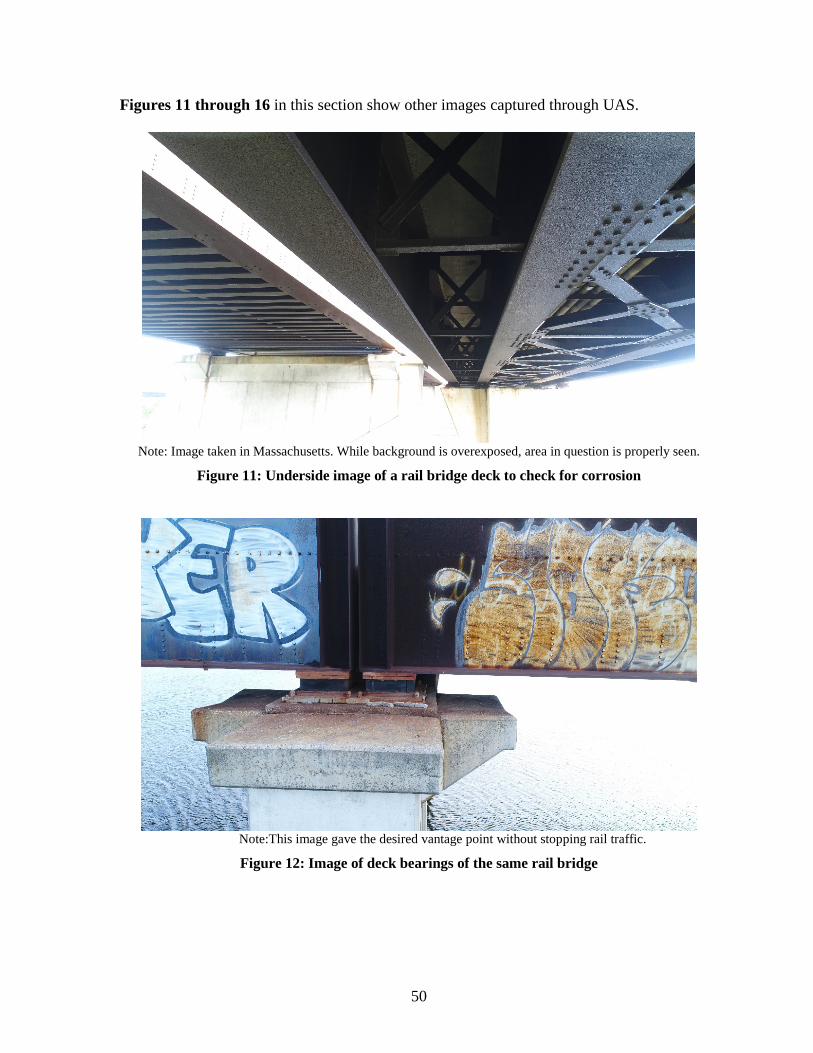
50
Figures 11 through 16 in this section show other images captured through UAS.
Note: Image taken in Massachusetts. While background is overexposed, area in question is properly seen.
Figure 11: Underside image of a rail bridge deck to check for corrosion
Note:This image gave the desired vantage point without stopping rail traffic.
Figure 12: Image of deck bearings of the same rail bridge

51
Note: This image is actually an ortho photo made of several dozen photos.
Figure 13: Image of bridge pier, New Jersey

52
Figure 14: Image of underside bridge truss, New York
Note:Image was captured in just a few minutes, without slowing traffic.
Figure 15: Image of bridge bearing, Massachusetts

53
Note: The purpose of the video was for asset management during a refurbishment.
Figure 16: Screen shot from video, New Jersey

54
Appendix C: UAV Flight Risk Assessment Conducted Pre-Flight
Prior to each flight, the PIC and SIC/VO will each complete a Flight Risk Analysis Template (FRAT). See sample template (Table 6) on next page.

55
Table 6: Flight Risk Analysis Template (FRAT)
Before each flight, assess each of the following conditions and assign a numerical rating of 1 to 5 in the right-hand (Rating) column. Add up the entries in the Rating column to obtain an overall risk estimate and see where it falls in the Green/Yellow/Red Risk Chart.
Add up the entries in the Rating column to obtain an overall risk estimate and see where it falls in the Green/Yellow/Red Risk Chart.
Pilot Observer Observer Points 1 2 3 4 5 Rating
Location Wide Open & Remote
Open Space but Suburbs
Confined Space & Suburbs
Congested & Urban*
Airspace Class E & G
Class D*** Class C***
Class B*** Special Use***
Crewmembers Pilot & Observers
Pilot & 1 Observer
Pilot Only
Drone Experience
Primary Drone & > 100 hours
Primary Drone & < 100 hours
Primary Drone & < 50 hours
Unfamiliar Drone
Unfamiliar, Drone
Testing*
Sleep in last 24 hrs
>7 hrs 6-7 hrs 3-5 hrs 3-4 hrs <3 hrs*
Alcohol past 8 hours
0 drinks 1 drink 8 hours ago
drank < 8 hours ago**
UAV Condition New and Tested
Reliable & Inspected
Fair & Inspected
Fair & Uninspected
Damaged & Uninspected*
Visibility > 3miles >2 miles >1 mile < 1 mile <1/2 mile* Ceiling > 1,000 ft. 500 –
1,000 ft. < 500*
Wind Calm 5-10 mph 10-15 mph
15-20 mph >20 mph*
Hours in last 90 days
>20 hrs 15-20 hrs. 10-15 hrs < 10 hrs <5*
TOTAL Green: No unusual hazards. Use normal flight planning and established personal minimums and operating procedures.
10-20
Yellow: Somewhat riskier than usual. Conduct flight planning with extra care. Review personal minimums and operating procedures to ensure that all standards are being met. Consider alternatives to reduce risk
21-33 or a 5 in any row
Red: Conditions present much higher than normal risk. Conduct flight planning with extra care and review all elements to identify those that could be modified to reduce risk. If available, consult with more experienced pilot or instructor for guidance before flight. Develop contingency plans before flight to deal with high risk items. Decide beforehand on alternates and brief passengers and other crewmembers on special precautions to be taken during the flight. Consider delaying flight until conditions improve and risk is reduced.
33-45 or a 5 in any 2 rows or alcohol < 8 hours ago
*A score of five in any three categories results in a cancelation of flight **Alcohol consumed in less than eight hours results in a cancellation of flight *** FAA approvals required

56
Appendix D: Flight Training Records
Figure 17: Flight Training Record for pre-launch (p. 1)
Figure 18: Flight Training Record for pre-launch (p. 2)
1 2 3 4 5
Aircraft Assesmbly
Mission Area and Pre-Launch Preparation
Systems Checks and Procedures
Document Check
RC Controller
Check
Compass Calibration
Mission Planning
Date Tasks Flight Time Total Time Aircraft4/16/2019 1-6 0.5 0.5 P4/P4P S S S S S S S4/16/2019 7,8 0.5 1 P4/P4P S S S S S S S4/16/2019 9,10 0.5 1.5 P4/P4P S S S S S S S4/16/2019 11 0.5 2 P4/P4P S S S S S S S4/16/2019 12,13 0.5 2.5 P4/P4P S S S S S S S4/16/2019 14,15 0.5 3 P4/P4P S S S S S S S4/16/2019 Review 0.5 3.5 P4/P4P S S S S S S S4/16/2019 Review 0.5 4 P4/P4P S S S S S S S4/16/2019 Review 0.5 4.5 P4/P4P S S S S S S S4/16/2019 16-21 0.5 5 P4/P4P S S S S S S S4/16/2019 22-26 0.5 5.5 P4/P4P S S S S S S S4/16/2019 27,28 0.5 6 P4/P4P S S S S S S S4/16/2019 29,30 0.5 6.5 P4/P4P S S S S S S S4/16/2019 31 0.5 7 P4/P4P S S S S S S S
Pre-Launch
Name: Joey Bagadonuts Task Number:
6 7 8 9 10 11 12 13 14 15 16 17 18 19
TakeoffFlight
Control Checks
Left Stick Maneuvers
Right Stick Maneuvers
Nose Out Climb to Position
Rectangular Course
Climb to Set
Altitude
Situational Awareness Att./Alt./Dir.
Stationary Object
Tracking (FPV)
Moving Object
Tracking (FPV)
If Possible
Figure 8 Approach & Landing
Max Effort Landing
Return To Home
S S S S S S S S S S S S S SS S S S S S S S S S S S S SS S S S S S S S S S S S S SS S S S S S S S S S S S S SS S S S S S S S S S S S S SS S S S S S S S S S S S S SS S S S S S S S S S S S S SS S S S S S S S S S S S S SS S S S S S S S S S S S S SS S S S S S S S S S S S S SS S S S S S S S S S S S S SS S S S S S S S S S S S S SS S S S S S S S S S S S S SS S S S S S S S S S S S S S
Basic Maneuvers

57
Figure 19: Flight Training Record for advanced maneuvers
Figure 20: Flight Training Record for emergency procedures
20 21 22 23 24 25 26 27 28 29 30 31 32
Intelligent Mode
Identification
Course Lock Mode
Home Lock Mode
Point of Interest Mode
Active Track Mode TapFly Mode Waypoints
ModeFollow Me
ModeCinematic Mode
Tripod Mode
Fixed Wing Mode
Terrain Follow Mode
Draw Mode
S S S S S S S S S S S S SS S S S S S S S S S S S SS S S S S S S S S S S S SS S S S S S S S S S S S SS S S S S S S S S S S S SS S S S S S S S S S S S SS S S S S S S S S S S S SS S S S S S S S S S S S SS S S S S S S S S S S S SS S S S S S S S S S S S SS S S S S S S S S S S S SS S S S S S S S S S S S SS S S S S S S S S S S S SS S S S S S S S S S S S S
Advanced Maneuvers
33 34 35 36 37 38 39 40 41 42
Emergency Procedures
Return to Home
GPS Loss
Communication Signal Loss
Low Battery
Airspace Incursion Fire Academics
Crew Resource
ManagementSafety
S S S S S S S S S SS S S S S S S S S SS S S S S S S S S SS S S S S S S S S SS S S S S S S S S SS S S S S S S S S SS S S S S S S S S SS S S S S S S S S SS S S S S S S S S SS S S S S S S S S SS S S S S S S S S SS S S S S S S S S SS S S S S S S S S SS S S S S S S S S S
Emergency Procedures