the basics of used oil sampling
DESCRIPTION
This document provides a good guide of important things to remember when sampling oil in machines.TRANSCRIPT

11/9/2014 The Basics of Used Oil Sampling
http://www.machinerylubrication.com/Articles/Print/650 1/11
The Basics of Used Oil SamplingJim Fitch, Noria Corporation Drew Troyer Tags: lubricant sampling, oil analysis
Practicing Oil Analysis (9/2004)
Proper oil sampling is critical to an effective oil analysis program. Without a representative sample, further oilanalysis endeavors are futile. There are two primary goals in obtaining a representative oil sample. The first goalis to maximize data density. The sample should be taken in a way that ensures there is as much information permilliliter of oil as possible. This information relates to such criteria as cleanliness and dryness of the oil, depletionof additives, and the presence of wear particles being generated by the machine.
The second goal is to minimize data disturbance. The sample should be extracted so that the concentration ofinformation is uniform, consistent and representative. It is important to make sure that the sample does notbecome contaminated during the sampling process. This can distort and disturb the data, making it difficult todistinguish what was originally in the oil from what came into the oil during the sampling process.
To ensure good data density and minimum data disturbance in oil sampling, the sampling procedure, samplingdevice and sampling location should be considered. The procedure by which a sample is drawn is critical to thesuccess of oil analysis. Sampling procedures should be documented and followed uniformly by all members ofthe oil analysis team. This ensures consistency in oil analysis data and helps to institutionalize oil analysis withinthe organization. It also provides a recipe for success to new members of the team.
The hardware used to extract the sample should not disturb sample quality. It should be easy to use, clean,rugged and cost-effective. In addition, it is important to use the correct bottle type and bottle cleanliness toassure that a representative sample is achieved.
A successful oil analysis program requires an investment of time and money to make sure the proper samplinghardware is fitted to the machinery. It is important to understand that not all locations in a machine will producethe same data. Some are far richer in information than others. In addition, some machines require multiplesampling locations to answer specific questions related to the machine’s condition, usually on an exceptionbasis.
Sampling on System Returns There are several rules for properly locating oil sampling ports on circulating systems. These rules cannot alwaysbe precisely followed because of various constraints in the machine’s design, application and plant environment.However, the rules outlined below should be followed as closely as possible:
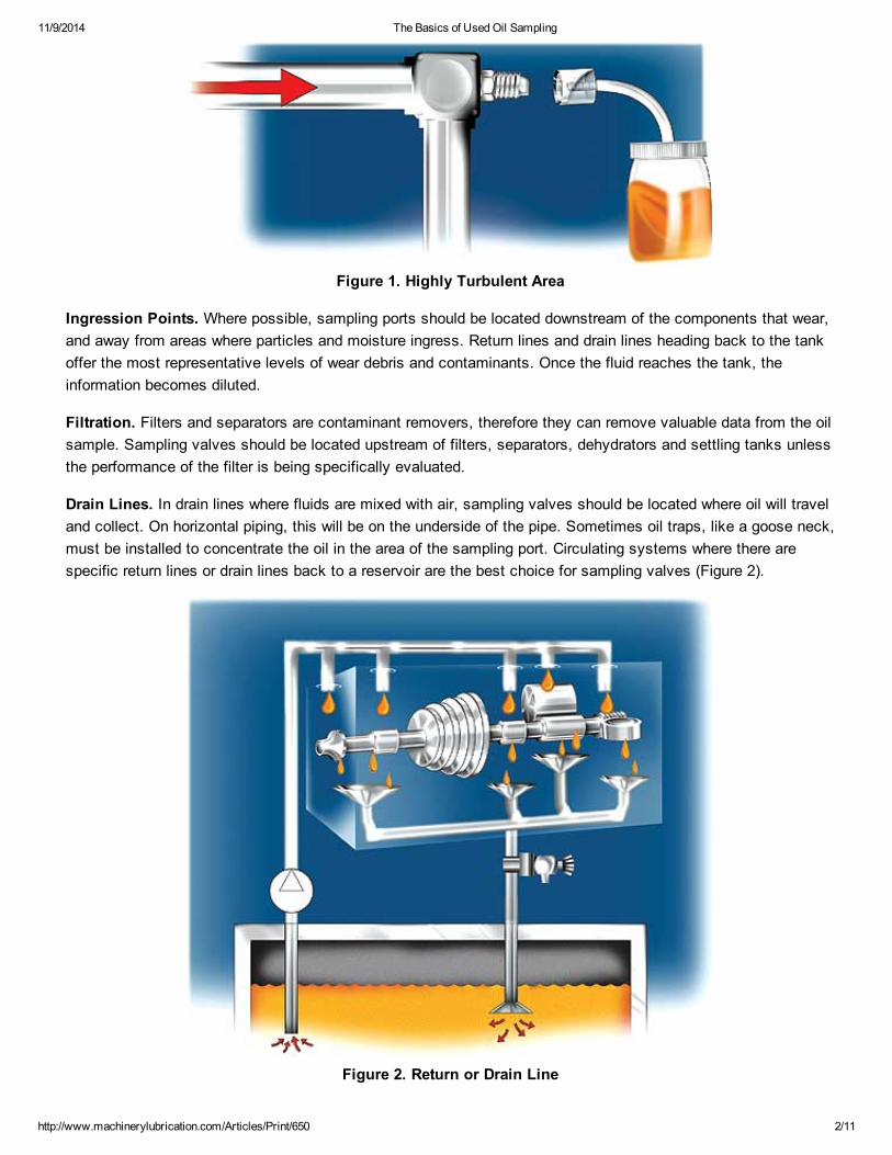
Turbulence. The best sampling locations are highly turbulent areas where the oil is not flowing in a straight linebut is turning and rolling in the pipe. Sampling valves located at right angles to the flow path in long straightsections of pipe can result in particle fly-by, which basically leads to a substantial reduction of the particleconcentration entering the sample bottle. This can be avoided by locating sampling valves at elbows and sharpbends in the flow line (Figure 1).
11/9/2014 The Basics of Used Oil Sampling
http://www.machinerylubrication.com/Articles/Print/650 2/11
Figure 1. Highly Turbulent Area
Ingression Points. Where possible, sampling ports should be located downstream of the components that wear,and away from areas where particles and moisture ingress. Return lines and drain lines heading back to the tankoffer the most representative levels of wear debris and contaminants. Once the fluid reaches the tank, theinformation becomes diluted.
Filtration. Filters and separators are contaminant removers, therefore they can remove valuable data from the oilsample. Sampling valves should be located upstream of filters, separators, dehydrators and settling tanks unlessthe performance of the filter is being specifically evaluated.
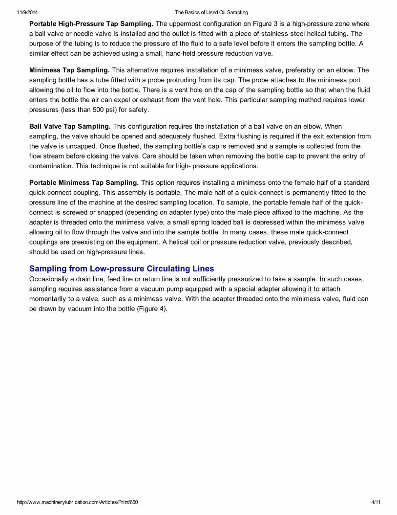
Drain Lines. In drain lines where fluids are mixed with air, sampling valves should be located where oil will traveland collect. On horizontal piping, this will be on the underside of the pipe. Sometimes oil traps, like a goose neck,must be installed to concentrate the oil in the area of the sampling port. Circulating systems where there arespecific return lines or drain lines back to a reservoir are the best choice for sampling valves (Figure 2).
Figure 2. Return or Drain Line

11/9/2014 The Basics of Used Oil Sampling
http://www.machinerylubrication.com/Articles/Print/650 3/11
They allow the sample to be taken before the oil returns to the tank and always before it goes through a filter. Ifthe oil is permitted to return to the tank, then the information in the sample becomes diluted, potentially bythousands of gallons of fluid in large lubricating and hydraulic systems. In addition, debris in the reservoir tendsto accumulate over weeks and months and may not accurately represent the current condition of the machine.
Live Zone Sampling from Circulating SystemsWhen a sample is taken from a line in a circulating system it is referred to as a live zone sample. There arethings that can be done during the sampling process that improve the quality and effectiveness of live zone oilsampling. These include sampling from the system’s turbulent zones where the fluid is moving and the oil is wellmixed; sampling downstream of the equipment after it has completed its primary functions, such as lubricating abearing or a gear or has passed through a hydraulic pump or actuator; sampling during typical working conditions,on the run and under normal applications; and, where required, employing secondary sampling locations tolocalize problems.
Just as there are factors that can improve the quality of a sample, there are also other factors that can diminish asample’s quality and thus should be avoided. For example, it is important not to sample from dead pipe legs,hose ends and standing pipes where the fluid isn’t moving or circulating. Samples should not be collected afterfilters or separators or after an oil change, filter change or at some time when the fluid wouldn’t represent typicalconditions. Samples should not be taken when the machine is cold and hasn’t been operating or has been idling.In addition, samples should not be taken from laminar flow zones where a lack of fluid turbulence occurs.
Sampling from Pressurized Lines When samples need to be taken from pressurized feed lines leading to bearings, gears, compressors, pistons,etc., the sampling method is simpler. Figure 3 shows four different configurations.
Figure 3. Pressurized Lines
11/9/2014 The Basics of Used Oil Sampling
http://www.machinerylubrication.com/Articles/Print/650 4/11
Portable High-Pressure Tap Sampling. The uppermost configuration on Figure 3 is a high-pressure zone wherea ball valve or needle valve is installed and the outlet is fitted with a piece of stainless steel helical tubing. Thepurpose of the tubing is to reduce the pressure of the fluid to a safe level before it enters the sampling bottle. Asimilar effect can be achieved using a small, hand-held pressure reduction valve.
Minimess Tap Sampling. This alternative requires installation of a minimess valve, preferably on an elbow. Thesampling bottle has a tube fitted with a probe protruding from its cap. The probe attaches to the minimess portallowing the oil to flow into the bottle. There is a vent hole on the cap of the sampling bottle so that when the fluidenters the bottle the air can expel or exhaust from the vent hole. This particular sampling method requires lowerpressures (less than 500 psi) for safety.
Ball Valve Tap Sampling. This configuration requires the installation of a ball valve on an elbow. Whensampling, the valve should be opened and adequately flushed. Extra flushing is required if the exit extension fromthe valve is uncapped. Once flushed, the sampling bottle’s cap is removed and a sample is collected from theflow stream before closing the valve. Care should be taken when removing the bottle cap to prevent the entry ofcontamination. This technique is not suitable for high- pressure applications.
Portable Minimess Tap Sampling. This option requires installing a minimess onto the female half of a standardquick-connect coupling. This assembly is portable. The male half of a quick-connect is permanently fitted to thepressure line of the machine at the desired sampling location. To sample, the portable female half of the quick-connect is screwed or snapped (depending on adapter type) onto the male piece affixed to the machine. As theadapter is threaded onto the minimess valve, a small spring loaded ball is depressed within the minimess valveallowing oil to flow through the valve and into the sample bottle. In many cases, these male quick-connectcouplings are preexisting on the equipment. A helical coil or pressure reduction valve, previously described,should be used on high-pressure lines.
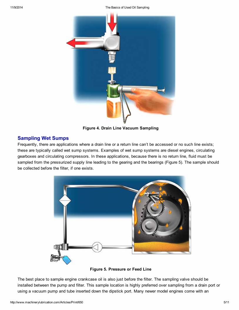
Sampling from Low-pressure Circulating LinesOccasionally a drain line, feed line or return line is not sufficiently pressurized to take a sample. In such cases,sampling requires assistance from a vacuum pump equipped with a special adapter allowing it to attachmomentarily to a valve, such as a minimess valve. With the adapter threaded onto the minimess valve, fluid canbe drawn by vacuum into the bottle (Figure 4).
11/9/2014 The Basics of Used Oil Sampling
http://www.machinerylubrication.com/Articles/Print/650 5/11
Figure 4. Drain Line Vacuum Sampling
Sampling Wet Sumps Frequently, there are applications where a drain line or a return line can’t be accessed or no such line exists;these are typically called wet sump systems. Examples of wet sump systems are diesel engines, circulatinggearboxes and circulating compressors. In these applications, because there is no return line, fluid must besampled from the pressurized supply line leading to the gearing and the bearings (Figure 5). The sample shouldbe collected before the filter, if one exists.
Figure 5. Pressure or Feed Line
The best place to sample engine crankcase oil is also just before the filter. The sampling valve should beinstalled between the pump and filter. This sample location is highly preferred over sampling from a drain port orusing a vacuum pump and tube inserted down the dipstick port. Many newer model engines come with an

11/9/2014 The Basics of Used Oil Sampling
http://www.machinerylubrication.com/Articles/Print/650 6/11
appropriately located sample valve right on the filter manifold.
Figure 6. Off-line Sampling
Another example of a wet sump involving circulation is shown in Figure 6 where there is a side loop that is oftenreferred to as a kidney loop filter. This off-line circulating system provides an ideal location to install a samplingvalve between the pump and filter. A ball valve or a minimess valve can be used so that the fluid under pressureflows easily into the sample bottle without disturbing the operating system or filtration system.
Sampling Noncirculating Systems There are numerous examples where no forced circulation is provided and a sample must be taken from asystem’s sump or casing. This often must be done with “in-service” equipment on the run. Ring or collar bath-lubricated bearings and splash-lubricated gearboxes are common examples of these systems. All of thesesituations increase the challenge of obtaining a representative sample.
The most basic method for sampling such sumps is to remove the drain plug from the bottom of the sumpallowing fluid to flow into the sample bottle. For many reasons, this is not an ideal sampling method or location.Most important is the fact that bottom sediment, debris and particles (including water) enter the bottle inconcentrations that are not representative of what is experienced near or around where the oil lubricates themachine. The drain plug sampling method should be avoided if at all possible.
Drain port sampling can be greatly improved by using a short length of tubing, extending inward and up into theactive moving zone of the sump. This ball valve and tube assembly shown in Figure 7 can, in many cases, bethreaded into the drain port and can be easily removed to facilitate draining the oil. Ideally, the tip of the tube,where the oil sample is taken should be half way up the oil level, two inches in from the walls and at least twoinches from the rotating elements within the sump.
11/9/2014 The Basics of Used Oil Sampling
http://www.machinerylubrication.com/Articles/Print/650 7/11
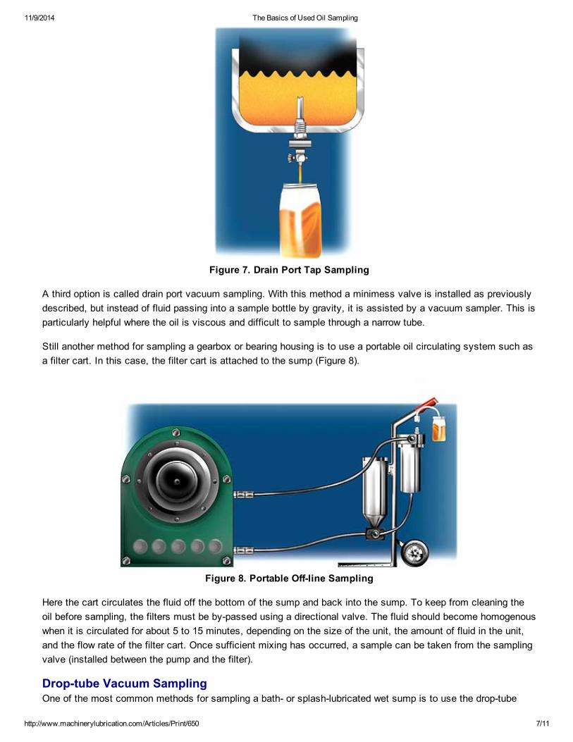
Figure 7. Drain Port Tap Sampling
A third option is called drain port vacuum sampling. With this method a minimess valve is installed as previouslydescribed, but instead of fluid passing into a sample bottle by gravity, it is assisted by a vacuum sampler. This isparticularly helpful where the oil is viscous and difficult to sample through a narrow tube.
Still another method for sampling a gearbox or bearing housing is to use a portable oil circulating system such asa filter cart. In this case, the filter cart is attached to the sump (Figure 8).
Figure 8. Portable Off-line Sampling
Here the cart circulates the fluid off the bottom of the sump and back into the sump. To keep from cleaning theoil before sampling, the filters must be by-passed using a directional valve. The fluid should become homogenouswhen it is circulated for about 5 to 15 minutes, depending on the size of the unit, the amount of fluid in the unit,and the flow rate of the filter cart. Once sufficient mixing has occurred, a sample can be taken from the samplingvalve (installed between the pump and the filter).
Drop-tube Vacuum Sampling One of the most common methods for sampling a bath- or splash-lubricated wet sump is to use the drop-tube
11/9/2014 The Basics of Used Oil Sampling
http://www.machinerylubrication.com/Articles/Print/650 8/11
vacuum sample method. A tube is inserted through a fill port or dip stick port and lowered into the sump cavity,usually about midway into the oil level. This sampling method has a number of drawbacks and should be avoidedif the sampling methods previously described can be used instead.
Some of the primary risks and problems associated with drop-tube vacuum sampling are:
Tube Location. A tube that is directed into the fill or dipstick port is extremely difficult to control. The tube’s finalresting place is hard to predict, resulting in samples being taken from different locations each time. There is alsoa risk of the tube actually going all the way to the bottom of the sump where debris and sediment are picked up.
Drop Tube Contamination. There is considerable concern that when the tube is being inserted into the sump itwill scoop up debris from the sides of the casing. Also, the tube itself may be contaminated due to poorcleanliness control when it was produced or while it was stored.
Large Flush Volume. The drop-tube method substantially increases the volume of fluid that must be flushed toobtain a representative sample. For some small sump systems this practically results in an oil change. Inaddition, if the removed volume of fluid is not replaced, the machine might be restarted with inadequate lubricantvolume.
Particle Fallout. For most systems, a shutdown is required to deploy the drop-tube method. This means thatproduction must be disturbed for the sake of oil sampling, or sampling frequency must suffer because ofproduction priorities. Neither situation is ideal. Futhermore, particles begin to settle and stratify according to sizeand density immediately upon shutdown, compromising the quality of oil analysis.
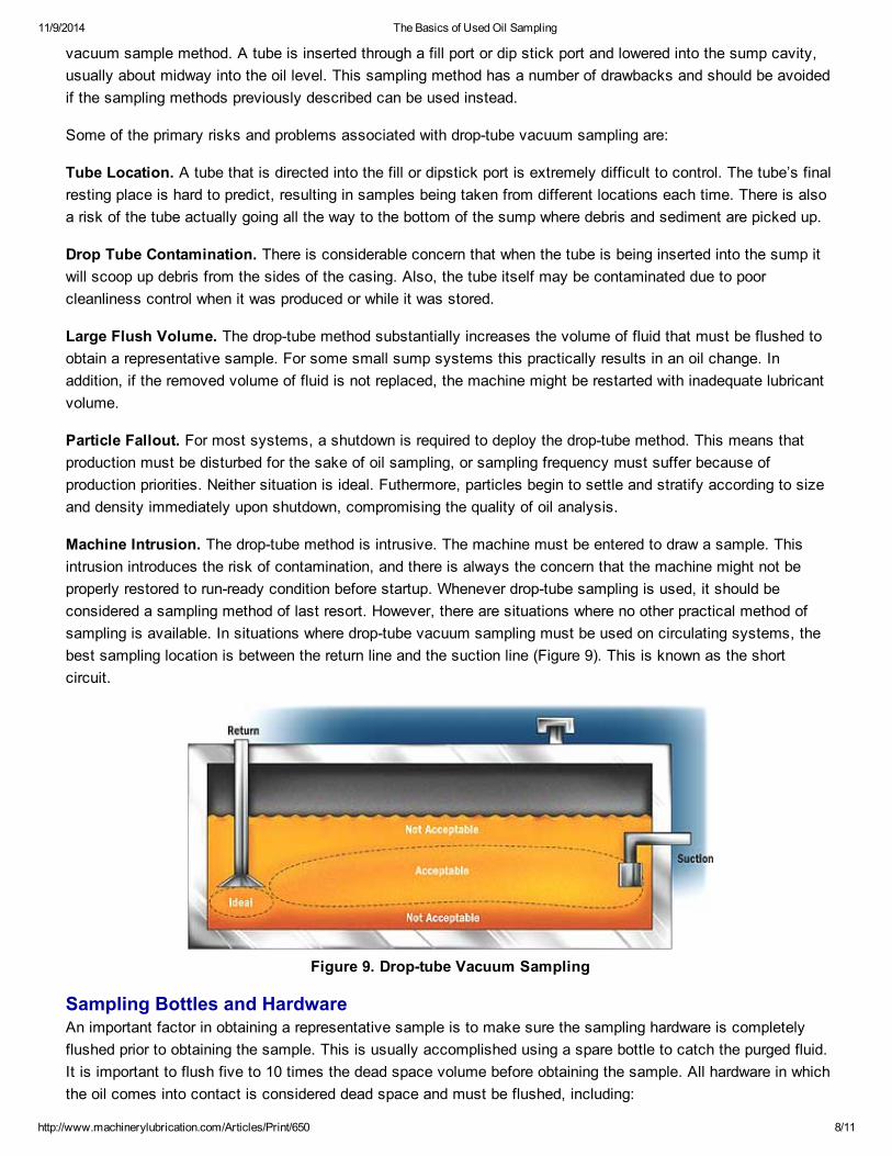
Machine Intrusion. The drop-tube method is intrusive. The machine must be entered to draw a sample. Thisintrusion introduces the risk of contamination, and there is always the concern that the machine might not beproperly restored to run-ready condition before startup. Whenever drop-tube sampling is used, it should beconsidered a sampling method of last resort. However, there are situations where no other practical method ofsampling is available. In situations where drop-tube vacuum sampling must be used on circulating systems, thebest sampling location is between the return line and the suction line (Figure 9). This is known as the shortcircuit.
Figure 9. Drop-tube Vacuum Sampling
Sampling Bottles and HardwareAn important factor in obtaining a representative sample is to make sure the sampling hardware is completelyflushed prior to obtaining the sample. This is usually accomplished using a spare bottle to catch the purged fluid.It is important to flush five to 10 times the dead space volume before obtaining the sample. All hardware in whichthe oil comes into contact is considered dead space and must be flushed, including:

11/9/2014 The Basics of Used Oil Sampling
http://www.machinerylubrication.com/Articles/Print/650 9/11
System dead-legsSampling ports, valves and adaptersProbe on sampling devicesAdapters for using vacuum sample extraction pumpsPlastic tubing used for vacuum pumps (this tubing should not be reused to avoid cross-contaminationbetween oils)
There is an assortment of sampling bottles that are commonly used in oil analysis. An appropriate bottle needs tobe selected for the application and the test that is planned. Several features including size, material andcleanliness must be considered when selecting a sample bottle.
A number of different-sized sampling bottles are available. They vary from 50 mL (or about two ounces of fluid) toa more common 100 to 120 mL bottle. The larger bottle is preferred when tests such as particle count andviscosity analysis are required. Where a considerable number of different tests are required, a 200 ml bottle (ortwo 100 ml bottles) may be required. It is important to coordinate with the laboratory to select the bottle size thatwill provide a sufficient volume to conduct all the required tests and leave some extra for storage in case a rerunis necessary.
Another consideration in selecting the bottle size is that the entire volume of the bottle should not be filled withfluid during the sampling process. Only a portion of the sampling bottle should be filled. The unfilled portion,called the ullage, is needed to allow proper fluid agitation by the laboratory to restore even distribution ofsuspended particles and water in the sample. The general guidelines for filling bottles are:
Low Viscosity (ISO VG 32 or less) - Fill to about three-fourths of the total volume.Medium Viscosity (ISO VG 32 to ISO VG 100) - Fill to about two-thirds of the total volume.High Viscosity (over ISO VG 100) - Fill to about one-half of the total volume.
Bottles are available in several materials. Plastic polyethylene is one of the most common bottle materials. It isan opaque material similar to a plastic milk jug. This type of sampling bottle presents a drawback because the oilcan’t be visually examined after the sample is obtained. Important oil properties, such as sediment, darkness,brightness, clarity and color, can be immediately learned from a visual inspection.
Another material is PET plastic. It is a completely clear, glass-like material and is available in standard-sizedbottles. This plastic is found to be compatible with most types of lubricating oils and hydraulic fluids, includingsynthetics.
Of course, glass bottles are also available. These bottles tend to be more expensive, are heavier, and there isthe risk of breakage during the sampling process. One advantage with glass bottles is that they can be cleanedand used over and over. The cleanliness of glass bottles often exceeds that of plastic bottles.
One of the most important considerations in selecting a sampling bottle is to make sure it is sufficiently clean.The bottle’s required cleanliness level should be determined in advance. (See the article titled “Bottle Cleanliness:Is a New Standard Needed?” in the March-April 2003 issue of Practicing Oil Analysis magazine for additionalinformation on sample bottle cleanliness.)
Conclusion All oil analysis tools, techniques and diagnostic processes are worthless if the oil sample fails to effectivelyrepresent the actual condition of the oil in service in the machine. Proper sampling procedures are the foundationof an effective oil analysis program. Without good sampling procedures, time and money are wasted, andincorrect conclusions based upon faulty data could be reached. To ensure that an oil analysis program isperceived as valuable and to boost confidence in the program, it is important to determine, understand and

11/9/2014 The Basics of Used Oil Sampling
http://www.machinerylubrication.com/Articles/Print/650 10/11
practice the processes that are necessary to obtain a representative oil sample.
Editor’s Note This article is an abridged version of Chapter 4 from Oil Analysis Basics written by Drew Troyer and Jim Fitchand published by Noria Corporation. More information about the book can be obtained by visiting NoriaCorporation’s online store at www.noria.com.
Sidebar 1Important Tips for Effective Oil Sampling To achieve bull’s-eye oil analysis data, where oil sampling and analysis produce the most representative andtrendable information, follow these basic sampling tactics:
1) Machines should be running in application during sampling. That means samples should be collected whenmachines are at normal operating temperatures, loads, pressures and speeds on a typical day. If that isachieved, the data will be typical as well, which is exactly what is desired.
2) Always sample upstream of filters and downstream of machine components such as bearings, gears, pistons,cams, etc. This will ensure the data is rich in information. It also ensures that no data (such as particles) is beingremoved by filters or separators.
3) Create specific written procedures for each system sampled. This ensures that each sample is extracted in aconsistent manner. Written procedures also help new team members quickly learn the program.
4) Ensure that sampling valves and sampling devices are thoroughly flushed prior to taking the sample. Vacuumsamplers and probe-on samplers should be flushed too, and if there are any questions about the cleanliness ofthe bottle itself, it should also be flushed.
5) Make sure that samples are taken at proper frequencies and that the frequency is sufficient to identifycommon and important problems. Record the hours on the oil where possible, especially with crankcase and drivetrain samples. This can be a meter reading or some other record identifying the amount of time that the oil hasbeen in the machine. If there has been any makeup fluid added or any change to the oil such as the addition ofadditives, a partial drain or anything similar, communicate this information to the lab.
6) Forward samples immediately to the oil analysis lab after sampling. The properties of the oil in the bottle andthe oil in the machine begin to drift apart the moment after the sample is drawn. Quickly analyzing the sampleensures the highest quality and timely decisions.
Sidebar 2Corn Milling Plant Learns the Value of Proper Sampling Under the guidance of Jim Smith of Allied Services Group, a corn milling plant in the southern United Statesstarted an oil analysis program in the fall of 2003. With a predominance of conveyors and other milling equipment,a significant number of the plant’s critical assets are large splash-lubricated gearboxes.
In early fall, all the plant’s critical gearboxes were sampled. Because the equipment was not equipped for bestpractice oil sampling - though a sampling point survey was planned - there was no choice but to use the drop tubemethod to obtain the samples. Even though plant personnel understood this was not the best method forsampling, with no other option, they decided a baseline sample before making any changes was warranted.
Fairly aggressive cleanliness targets of 18/16/13 for major gearboxes were set. Based on these targets, 28samples from these gearboxes were returned as “critical” due in every case to high particle counts.
11/9/2014 The Basics of Used Oil Sampling
http://www.machinerylubrication.com/Articles/Print/650 11/11
Immediately after the first baseline samples were taken, a sample point survey was conducted. Shortlythereafter, the report’s recommendation of installing pitot tube style sample valves in all of the plant’s splash-lubricated gearboxes was implemented, in conjunction with a filtration program.
At the prescribed time, these gearboxes were resampled, using the new sample valves, and submitted to the labfor analysis. Of the 28 boxes deemed initially to be “critical,” 22 of 28 were returned as “normal.”
Editors Note The moral of this story is that if you want to get accurate data, particularly where particle counting is a requiredtest, the use of appropriate sample valves is of paramount importance. To receive and act on an analysis reportthat indicates a “critical problem” but turns out to be nothing more than poor sampling, is the easiest way to erodeconfidence in any oil analysis program.