the cfd investigation of flash dryer and rotating kiln design
TRANSCRIPT

Second International Conference on CFD in the Minerals and Process IndustriesCSIRO, Melbourne, Australia6-8 December 1999
455
THE CFD INVESTIGATION OF FLASH DRYER AND ROTATING KILN DESIGN
Amir EGHLIMI1, Reg BENITO2, Krzysztof GOLAB3
1 CANCES, Australian Technology Park, Eveleigh, 1430, NSW, Australia2 CSIRO-Energy Technology, Sydney, Australia
3Southern Pacific Petroleum, Brisbane, Australia
ABSTRACT
The retorting or heating of oil-shale particles has beenmodelled using Fluent CFD code. The hydrocarboncomponent is an organic solid which can be liberated bythe application of heat, in order of 500°C. A number ofprocesses have been modelled in this study. A rotary kilnconsisting of a horizontal rotating cylindrical vessel hasbeen modelled. The mixing process of the oil-shale andretorted oil-shale particles in an Eulerian-Eulerian basisand the flash drying process of oil-shale and coal particlesin a Lagrangian approach are studied here. Further studywould look at oil-shale pyrolysis and combustion ofremaining carbon on the shale.
INTRODUCTION
CFD has increasingly been used to address multi-phaseflows occurring in many industrial applications such ascyclone separators, electrostatic precipitators, pneumaticconveyors and fluidised bed combustion. The increaseduse has been motivated by significant improvements in thecapabilities of various commercial CFD codes and majorreduction in the cost of computer hardware.
Much of the multi-phase flow problems involved dilutesolid phase in which the conventional Lagrangianapproach could be used to trace particles individually. Atwo-way coupling approach, in some cases, is sometimesused to consider mutual particle-fluid interactions. Fordense solid phase flows, Eulerian approach needs to beused in order to account for particle-to-particle as well asfluid-fluid and particle-fluid interactions. As can beexpected, computation times have been much longer withthis approach. The Lagrangian approach might becomecomputationally expensive if stockasting tracking ofparticles in a two-way coupling scheme is investigated.However, availability of cheaper computers with largememory and much faster processing speed and advances inCFD capabilities have recently allowed Eulerian andLagrangian approaches to be used in many industrialapplications.
In this paper, we present initial results in using the abovetwo approaches as applied to flash dryer and rotating solidmixers designs using Fluent CFD software. Lagrangianapproach has been used in modelling the drying process ofboth coal and oil-shale particles in a lift-pipe type column.As the second part of this investigation a 3D rotatingmixer has been modelled based on Eulerian approach toinvestigate mixing process of raw oil shale particles and
recycle combusted shale in a proposed rotating kiln typeretort.
PROBLEM DESCRIPTION
The technology of using oil shale particles to generate oilwas developed by William (Bill) Taciuk from UMATACIndustrial Processes and financially supported byAOSTRA - Alberta Oil Sands Technology and ResearchAuthority. The processor is called AOSTRA TaciukProcessor - ATP. The rotary kiln is the base of the ATPdesign based on four steps processing:
1. Preheat of shale2. Oil shale pyrolysis3. Combustion of remaining carbon on the shale4. Heat recovery from the hot, combusted shale
Figure 1 and 2 show how the ATP works. The shale is fedto the preheat tube. The temperature here increases to250°C. Through a seal it is then sent to the retort zone.The temperature reaches 500°C. At this stage thehydrocarbon vapour is generated which is drawn out andcondensed to a liquid. The remaining retorded shale istransferred to the combustion zone and is burnt to raise itstemperature to 750°C. The hot combusted shale is thenmixed with the preheated feed. This mixing produces thereaction temperature in the retort.
THE MODELLING APPROACH
Three different cases are studied here as the following:
1. The mixing process in rotating retord2. The flash dryer of oil-shale3. The flash dryer of coal particles
The first one is modelled using Eulerian-Eulerianapproach, which solves the momentum, continuity andspecies for each phase (Anderson and Jackson, 1967 andBowen, 1976). Coupling is achieved through the pressureand exchange coefficients. The flash dryer cases are basedon Lagrangian approach. The trajectory of oil-shale orcoal particles are modelled by integrating the forcebalance in a two-way coupling approach.In terms of boundary conditions, a polynomial wallvelocity is applied to the rotating drum. For the granularviscosity the Syamlal-O’Brien model, 1989, is used whichhas shown to be the appropriate model for granular flows.Due to the small rotating speed of the drum the mixtureflow is taken to be laminar.

456
RESULTS AND DISCUSSION
Solid Mixing in the Retort
Mixing of solids in the retort was simulated up to morethan 400 seconds, which is about twice the time it takes tofill an initially empty retort to a level that solids flow outof the retort exit. Instantaneous results at about 360seconds are presented in Figures 3 and 4 as contour plotsof volume fractions of shale and recycle shale at various Kand I slices. Note that the scale of the axis is the same forall cases with a maximum of 4m/s for velocity and 0.6 forvolume fraction. This allows easier comparison of theresults.Contour plots of volume fractions of raw oil shale andrecycle shale for various K and I slices show that:• Solids close to the wall of the retort were mainly
recycle shale especially on the side of recycle shaleinlet. This suggest possible inadequate mixing of rawoil shale and recycle shale.
• Mixing of incoming raw oil shale with the bulk of thesolids occurred mainly on the side opposite that ofthe recycle shale inlet.
• Recycle shale accumulated at the end of the mainsection of the retort. This is another possibleindication of inadequate mixing which tends toreduce effective volume of the retort.
• Some degree of back-mixing was indicated by thepresence of fairly large concentration of recycle shaleupstream of recycle shale inlet. This could be apositive effect and likely to be enhanced in the actualretort due to periodic disturbance of the bed by thesolids inlet port.
• Highest velocities (up to about 4m/s) occurred wherethe shale enters the retort and at the recycle shaleinlet.
• Velocities near the wall were lower than those nearthe centre.
Heating and Drying of Raw Oil-Shale in a Flash Dryer
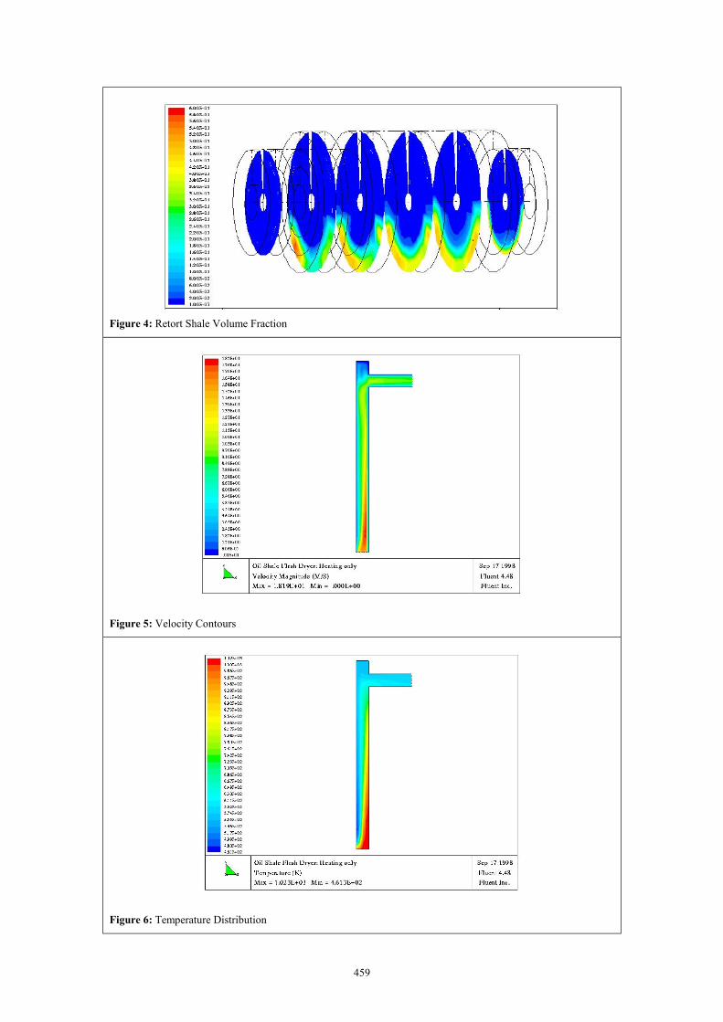
Contour plots of velocity and temperature of gas andparticle concentration are presented in Figures 5 and 6 forthe converged solution. Trajectory of top-size (8mm)particle is shown as an example in Figure 7. Extent ofdrying for assumed values of particle diffusivities andother results are summarised in Table 1.In general, gas with a velocity of 15 m/s at 1023K and 1atm could entrain particles with sizes up to 8mm in thehypothetical design of shale flash dryer.Contour and particle trajectory plots in the figures 5, 6 and7 clearly show that:• For up to more than half-way the length of the
vertical column, entrained particles stayed close toone side, the side of solids inlet.
• Fairly high concentration of particles occurred closeto the particle injection zone and at the top of thecolumn.
• All particles hit the column top and some bouncedseveral times before exiting the dryer.
All these results suggest that particle injection may need tobe located closer to the centre so the gas could dispersethem quickly across the column. When this is done, gasvelocities lower than 15 m/s could be adequate for thegiven solids loading.
Heating and Drying of Coal in a Flash Dryer
Rapid drying of coal particles is used as part of the retortoil shale processing system. The 3D grid, contour plots ofvelocity and temperature of gas are presented in Figures 8,9 and 10 for the converged solution of coal dryingprocess. A summary of simulation results for coal flashdryer is presented in Table 2. Case with finer grid showedsimilar exit gas temperatures and proportion of particlesescaping the dryer via exit. It, however, predicts lowerparticle size. The 3D case gave a much lower fullyentrained particle size and less particles escaping. Ingeneral, gas with a velocity of 25 m/s at 805K and 1 atmcould only entrain about 70% of incoming particles in theproposed design of coal flash dryer based on heating modeonly. With drying, this proportion appeared to increase byabout 10%, possibly due to additional gas (steam fromparticles). Increasing gas velocity to 30m/s could furtherensure all particles being entrained in drying mode basedon a 2D model. However, amount of moisture removeddecreased as may be expected due to shorter residencetimes of the particles in the dryer. Being similar in design,shale and flash dryer showed similar behaviour as shownin the contour and particle trajectory plots.
ParticleDiffusivity(m2/s)
Average exitparticle T(K)for a givenparticle size
Particleresidencetime (s)
Averageexit gasT (K)
Moistureremoved(%)
1.2e-7553 (0.025mm)565 (4.0mm)455 (8mm)
5118.4
571 10.6
3e-5430 (0.025mm)356 (4.0mm)485 (8mm)
4.81116.6
416 40.9
Table 1: Summary of results for oil shale flash dryersimulation.
Average exitparticle T(K)for a givenparticle size
Particleresidencetime (s)
Particlesescaped(%)
Averageexit gasT (K)
Moistureremoved(%)
Heatingonly2D coarsegrid25m/s gas
689 (0.025mm)552 (5.0mm) –max escaped635 (8mm) –max lifted
1.67.6
16.6
72 652 NA
Heatingonly2D finegrid25m/s gas
658 (0.025mm)625 (4.0mm) –max escaped609 (4.7mm) –max lifted
1.410
11
69 655 NA
Heatingonly3D coarsegrid25m/s gas
673 (0.025mm)647 (3.3mm) –max escaped
3.756 664 NA
Drying2D coarsegridDiff=3e-5
m2/s25m/s gas
643 (0.025mm)364 (4.6mm) –max escaped364 (5.2 mm) –
max lifted
1.68
6.7
82 552 91.1
Drying2D coarsegridDiff=3e-5
m2/s30m/s
680 (0.025mm)364 (6mm) –max escaped
1.76.7
100 593 87.4
Table 2: Summary of results for coal flash dryersimulation.

457
CONCLUSION
Simulations of the following models were successfullycompleted using Fluent:
• 3D Eulerian-granular model of cold mixing of1mm raw oil shale particles and 0.5mm recyclecombusted shale in an AOSTRA Taciuk retortrotating at 4 revolution per minute with anominal output of 55 tonnes per hour
• 2D and 3D Lagrangian models of entrainment ofmulti-size coal particles with and without dryingin a 19m long lift-pipe column having adiameter of 0.84m
• 2D Lagrangian model of entrainment of multi-size oil shale particles with and without dryingin a 19m long lift-pipe column having adiameter of 1.5m
Some of the interesting insights that these CFDsimulations provided were as follows:
• Mixing of solids in the retort would appear to beinadequate.
• Some degree of back-mixing of recycle shale inthe retort was indicated by the presence ofsignificant concentrations of recycle shaleupstream of recycle shale inlet.
• A gas velocity of 15 m/s (at 1023oK and 1 atm)would appear to be too high in the shale flashdryer as all particles hit the top of the column.
• For the proposed design of coal flash dryer, agas velocity of 25 m/s (at 805oK and 1 atm)failed to entrain all of the particles. However, allparticles were entrained at a gas velocity of 30m/s.
• Based on assumed particle diffusivities, 10 to40% of the moisture in the wet shale could beremoved in the flash dryer. Two or more stagesof drying may therefore be required to achievecomplete drying.
• Based on assumed particle diffusivities, coalparticles that were entrained were almostcompletely dried in the proposed design at a gasvelocity of 25 m/s. However, moisture removaldecreased when gas velocity was increased to 30m/s as a result of lower particle residence times.
• The method of particle injection into the flashdryer may need to be improved as highconcentrations of particles were observed closeto the particle injection zone with both coal andshale. Moreover, entrained particles stayed closeto solids inlet side more than halfway up the lift-pipe column.
The limited study that was undertaken has indicated thatfurther modelling should consider:
• Refining the grid in both the retort and flashdryer geometries to check whether a grid-independent solution has been achieved.Solution adaption in Fluent/UNS, whichcurrently does not have Eulerian-granular (densephase) models, could also be applied in studyingthe solids inlet zone and various bends along thecolumn of the flash dryer, as densities close tothe point of injection exceeded recommendedlimits for Lagrangian (dilute-phase) models.
• Heat transfer and pyrolysis as well ascoking/cracking reactions in the retort to fullyassess this type of reactor.
• The effect of recycle shale solids inlet portwhich in an actual retort is fixed on the wall andextends beyond the wall boundaries, sweepingthe bed periodically and therefore significantlyaffecting bed mixing near the inlet.Unfortunately, the Eulerian-granular modelcurrently cannot be used to model this effect.One approach is to consider the secondary phase(particle) as a pseudo-fluid phase and apply aEulerian-Eulerian model and sliding meshtechnique. This will require an equivalentparticle phase viscosity be initially determinedexperimentally or established through a series ofEulerian-granular modelling.
• Different methods of introducing solids to theflash dryer with the aim of dispersing theparticles more evenly right near the bottom ofthe column.
• Effect of parameters such as gas and solids flowsand other conditions that could impact on theoperation of both the retort and the flash dryer.
REFERENCES
ANDERSON, T.B., and JACKSON, R. (1967), “A fluidmechanical description of fluidised beds”, I & ECFundam., 6, 527-534.
BOWEN, R.M., (1976), “Theory of mixtures”,Continuum Physics, Academic Press, NY, 1-127.
SYAMLAL, M., O’BRIEN, T. J., (1989), “Computersimulation of bubbles in a fluidised bed”, AIChE Symp.Series, 85, 22-31.

458
Figure 1: Cross Section of ATP
Figure 2: Material Flow through the ATP
Figure 3: Oil Shale Volume Fraction
459
Figure 4: Retort Shale Volume Fraction
Figure 5: Velocity Contours
Figure 6: Temperature Distribution

460
Figure 7: Oil Shale Trajectories Figure 8: The Grid for Coal Drying Modelling
Figure 9: Velocity Contours of Coal Particles Figure 10: Temperature Distribution of Coal Particles