the designing of small and medium sized milking machines for … copy/sheep/publications... ·...
TRANSCRIPT

THE DESIGNING OF SMALL AND MEDIUM SIZED MILKING MACHINES FOR DAIRY SHEEP
P. BILLON
Institut de l’Elevage BP 67, 35652 Le Rheu Cedex, France
Abstract
Basically, the ISO standard 5707 (Milking machines installations: construction and
performance) applies to milking machines for small ruminants for qualitative and quantitative requirements that are similar for dairy cattle such as vacuum regulation, sizing airlines, vacuum gages and receiver. Specific quantitative requirements for sheep were introduced by a group of experts within the International Dairy Federation (I.D.F.) and published in a bulletin in March 2002.
New recommendations, especially for vacuum pump capacity and effective reserve, are now available. For ewes, they take into account the type of cluster used, the number of operators with the type of machine (bucket or milkline) and the number of units. Vacuum pump capacity is also calculated referring to air used during the cleaning process (only for machine with milkline). Furthermore, regulation must be well adjusted in order to maintain a stable vacuum within the plant at every moment of milking.
Pulsation characteristics are important for ewes because they have a direct influence on stimulation of milk let-down. The best pulsation rate should be 150-180 cycles/min and a pulsator ratio of 50%.
Sizing milklines is similar to cows but taking into account the particular milk kinetics of the East-Friesian ewes and the type of cluster used.
Finally, recent recordings of vacuum beyond the teat and in the claw (or SMT) and of liner movements presented in this document can be useful for helping farmers in their choice of new equipment. Résumé
La norme de construction et de performances des machines à traire (ISO 5707) s’applique aux
petits ruminants, et en particulier aux brebis, uniquement pour les recommandations de type qualitatif. Des recommandations d’ordre quantitatif ont été proposées par un groupe d’experts internationaux au sein de la Fédération Internationale de Laiterie (F.I.L.) et on été publiées dans un bulletin de la FIL en 2002.
Les recommandations spécifiques pour les brebis portent d’abord sur la détermination de la capacité de la pompe à vide et la notion de Réserve Réelle. Pour les brebis, et contrairement aux vaches, elle est fonction, du type de faisceau trayeur utilisé et du nombre de trayeurs, mais aussi du type de machine (pots à terre ou lactoduc) et du nombre de postes de traite. La capacité de la pompe à vide doit aussi tenir compte des besoins en air pendant la phase de nettoyage (uniquement pour les installations avec lactoduc). De plus, la régulation du vide doit être assurée dans les meilleures conditions afin de permettre un vide le plus stable possible pendant la traite dans toute l’installation.

Les caractéristiques de pulsation chez les brebis sont les suivantes : 150 à 180 cycles/min avec un rapport de 50%. Elles ont une influence directe sur la stimulation de l’éjection du lait.
La détermination du diamètre intérieur du lactoduc est basée sur le même principe que pour les vaches en tenant compte des cinétiques d’émission du lait des brebis et en particulier celle de la race East-Friesian et également du type de faisceau trayeur utilisé.
Enfin, le choix du faisceau trayeur (griffe et manchon trayeur) est abordé à travers des récents enregistrements réalisés en laboratoire tenant en compte l’évolution du niveau de vide sous le trayon et les mouvements du manchon pendant la traite.
Introduction
A milking machine is an assembly of different components which have to work together in the best conditions in order to produce a milk of high quality and to secure udder health of milked animals.
Ewes, like other species such as cows and goats, are milked with a specific machine which
applies vacuum (under atmospheric pressure) under the teat in order to open the streak canal through which flows the milk held in the cistern of the gland.
Every component of the milking machine must be figured taking into account different
parameters such as: the breed and milk ability of animals, anatomy and physiology of udders, special needs of ewes, skill of operators, etc.
This document attempts to give an overview of the design of a milking machine for ewes. The
main parameters such as determination of the vacuum pump capacity with the right effective reserve (ER), sizing milklines and some considerations regarding clusters were discussed in an international group of experts and published in a bulletin of the International Dairy Federation (IDF).
Other results coming from our own researches and field observations are also described and
explained because they are useful to have a better understanding of how the milking machine works and its main effects on animals.
The Main Components of a Milking Machine
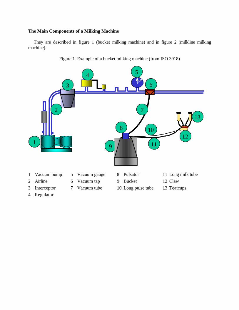
They are described in figure 1 (bucket milking machine) and in figure 2 (milkline milking machine).
Figure 1. Example of a bucket milking machine (from ISO 3918)
1 Vacuum pump 5 Vacuum gauge 8 Pulsator 11 Long milk tube 2 Airline 6 Vacuum tap 9 Bucket 12 Claw 3 Interceptor 7 Vacuum tube 10 Long pulse tube 13 Teatcups 4 Regulator
St
R
1
2
3
4 5
6
10
9
8
7
1211
13St
R
11
22
33
44 55
66
1010
99
88
77
12121111
1313

Figure 2. Example of a pipeline milking machine (from ISO 3918)
1 Vacuum pump 5 Vacuum gauge 9 Airline receiver 12 Long pulse tube 15 Teatcups 2 Main airline 6 Pulsator airline 10 Receiver 13 Long milk tube 16 Milk pump 3 Interceptor 7 Pulsator 11 Milkline 14 Claw 17 Delivery line 4 Regulator 8 Sanitary trap Effective Reserve and Vacuum Pump Capacity
The effective reserve (ER) can be defined as an indication of the reserve airflow capacity
actually available to maintain the vacuum within 2 kPa when air is accidentally admitted during milking. It is assumed that a vacuum drop of 2 kPa has little or no effect on milking performance.
It is also the difference between the vacuum pump capacity and the air consumption of the
different components of the milking machine as shown in figure 3.
St
R
1
2
3
4 5
6
10
98
7
12
11
13
14
15
1617
St
RR
11
22
33
44 55
66
1010
9988
77
1212
1111
1313
1414
1515
16161717
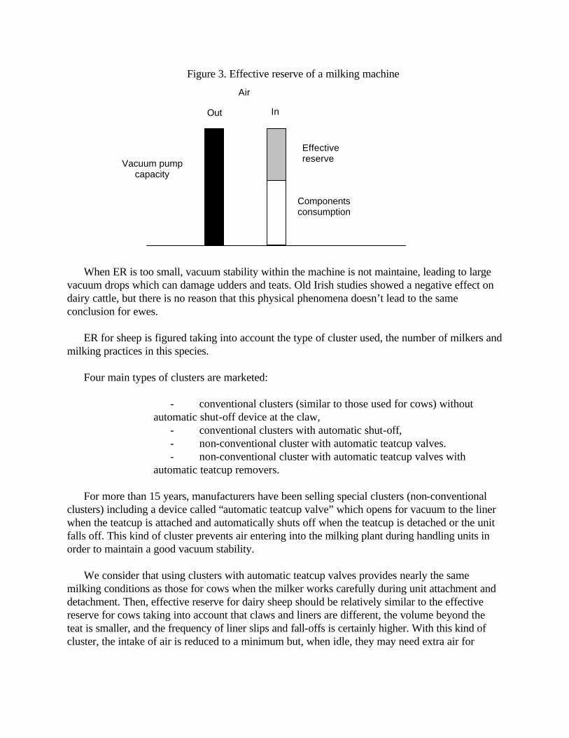
Figure 3. Effective reserve of a milking machine
When ER is too small, vacuum stability within the machine is not maintaine, leading to large
vacuum drops which can damage udders and teats. Old Irish studies showed a negative effect on dairy cattle, but there is no reason that this physical phenomena doesn’t lead to the same conclusion for ewes.
ER for sheep is figured taking into account the type of cluster used, the number of milkers and
milking practices in this species. Four main types of clusters are marketed:
- conventional clusters (similar to those used for cows) without automatic shut-off device at the claw,
- conventional clusters with automatic shut-off, - non-conventional cluster with automatic teatcup valves. - non-conventional cluster with automatic teatcup valves with
automatic teatcup removers. For more than 15 years, manufacturers have been selling special clusters (non-conventional
clusters) including a device called “automatic teatcup valve” which opens for vacuum to the liner when the teatcup is attached and automatically shuts off when the teatcup is detached or the unit falls off. This kind of cluster prevents air entering into the milking plant during handling units in order to maintain a good vacuum stability.
We consider that using clusters with automatic teatcup valves provides nearly the same
milking conditions as those for cows when the milker works carefully during unit attachment and detachment. Then, effective reserve for dairy sheep should be relatively similar to the effective reserve for cows taking into account that claws and liners are different, the volume beyond the teat is smaller, and the frequency of liner slips and fall-offs is certainly higher. With this kind of cluster, the intake of air is reduced to a minimum but, when idle, they may need extra air for
Air
In Out
Vacuum pump capacity
Components consumption
Effective reserve

working: 20 up to 50 l/min, depending on the model. This amount of extra air must be stated by the manufacturer.
With conventional clusters (similar to claw used for cows) without automatic shut-off valves
in the milking unit as defined in ISO 3918, the risk is very high that milkers do not shut off the vacuum at the liner when they attach and when they detach clusters from udders. In this case, ER should compensate at least for the total air admission of a fully open cluster, which has been evaluated at 600 litres/minute (21.2 cfm). In these conditions, and unlike dairy cows, the air admission during unit attachment depends particularly on the number of milkers because there is risk that different milkers may generate the same fault at the same time.
With conventional clusters with automatic shut-off valves, it is possible for the milker to work
more carefully when using this device. Then the air admission during attachment, which also depends on the number of milkers (more risks than for cows especially during attachments), should be similar to transient air entering into an installation for cows used by a normal operator.
The installation shall have a minimum ER determined in accordance with table 1. For each
kind of cluster, ER also depends on the type of installation (pipeline or bucket) and of the number of units.
Table 1: Minimum effective reserve for different types of clusters (in litres/minute of free air)
Minimum effective reserve a,
in l/min of free air
Number of units
n
Pipelines Buckets
Non-conventional cluster with automatic teatcup valve
n ≤ 10 200 + 20n + nE 100 + 20n + nE
> 10 400 + 10(n - 10) + nE 300 + 10(n - 10) + nE
Non-conventional cluster with automatic teatcup valve and automatic teatcup removal
n ≤ 10 200 + 20n
> 10 400 + 10(n - 10)
Conventional cluster without automatic shut-off valve
n ≤ 10 200 + 20n + 400M 100 + 20n + 200M
> 10 400 + 10(n - 10) + 400M 300 + 10(n - 10) + 200M
Conventional cluster with automatic shut-off valve
n ≤ 10 200 + 20n + 200M 100 + 20n + 100M
> 10 400 + 10(n - 10) + 200M 300 + 10(n - 10) + 100M
a Plus additional for ancillary equipment.

E = extra air needed for clusters equipped with automatic teatcup valves. M = number of milkers. n = number of units.

Tables 2 to 5 give some examples of ER for small and medium sized installations according to formulas given in table 1.
Table 2. Minimum effective reserve for milking, in l/min of free air: conventional clusters
without automatic shut-off at the claw (in cfm) No units Pipeline milking machines Bucket milking machines 1 milker 2 milkers 1 milker 2 milkers 2 640 (22.6) 1040 (36.7) 340 (12.0) 540 (19.1) 3 660 (23.2) 1060 (37.5) 360 (12.7) 560 (19.8) 4 680 (24.0) 1080 (38.2) 380 (13.4) 580 (20.5) 6 720 (25.4) 1120 (39.6) 8 760 (26.9) 1160 (41.0) 10 800 (28.3) 1200 (42.4) 12 820 (29.0) 1220( 43.1) 16 860 (30.4) 1260 (44.5)
Table 3. Minimum effective reserve for milking, in l/min of free air: conventional clusters with
automatic shut-off at the claw (in cfm) No
units Pipeline milking machines Bucket milking machines
1 milker 2 milkers 1 milker 2 milkers 2 440 (15.5) 640 (22.6) 240 (8.5) 340 (12.0) 3 460 (16.3) 660 (23.3) 260 (9.2) 360 (12.7) 4 480 (17.0) 680 (24.0) 280 (9.9) 380 (13.4) 6 520 (18.4) 720 (25.4) 320 (11.3) 420 (14.8) 8 560 (19.8) 760 (26.9) 360 (12.7) 460 (16.3) 10 600 (21.2) 800 (28.3) 400 (14.1) 500 (17.7) 12 620 (21.9) 820 (29.0) 420 (14.8) 520 (18.4) 16 660 (23.3) 860 (30.4) 460 (16.3) 560 (19.8)
Table 4. Minimum effective reserve for milking, in l/min of free air: non-conventional clusters
with automatic teatcup valves (examples with extra air of 20 l/min (0.7 cfm) and 40 l/min (10.4 cfm)) (in cfm)
Pipeline milking machines Bucket milking machines No units Extra air
20 l/min Extra air 40 l/min
Extra air 20 l/min
Extra air 40 l/min
2 280 (9.9) 320 (11.3) 180 (6.4) 220 (7.8) 3 320 (11.3) 380 (13.4) 220 (7.8) 280 (9.9) 4 360 (12.7) 440 (15.5) 260 (9.2) 340 (12.0) 6 440 (15.5) 560 (19.8) 8 520 (18.4) 680 (24.0) 10 600 (21.2) 800 (28.3) 12 660 (23.3) 900 (31.8) 16 780 (27.6) 1100 (38.9)
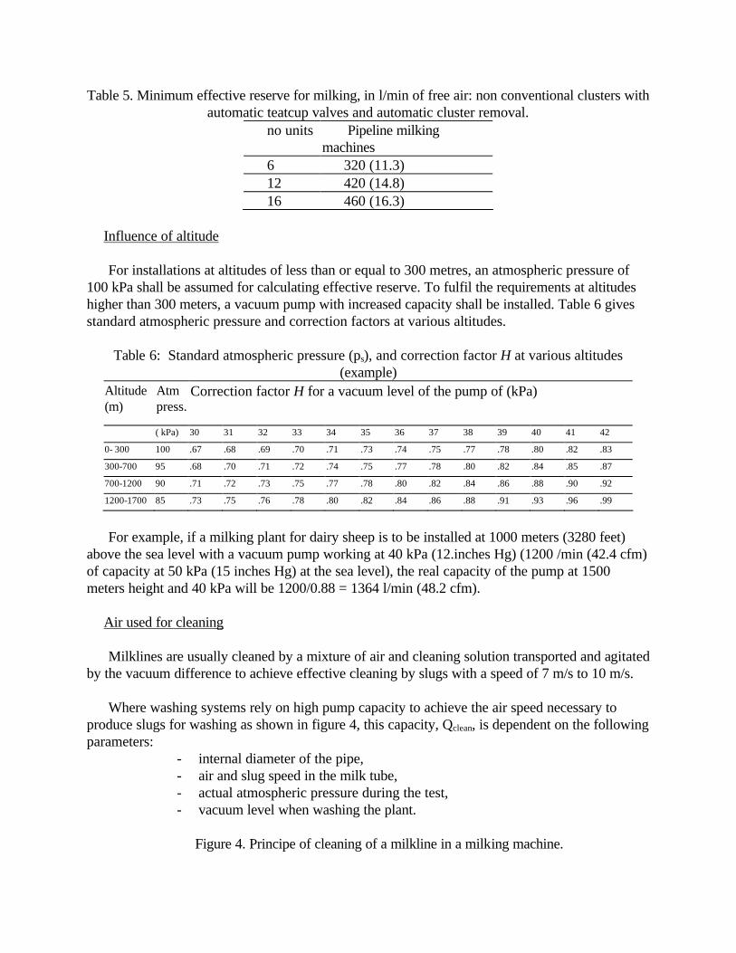
Table 5. Minimum effective reserve for milking, in l/min of free air: non conventional clusters with automatic teatcup valves and automatic cluster removal.
no units Pipeline milking machines
6 320 (11.3) 12 420 (14.8) 16 460 (16.3)
Influence of altitude For installations at altitudes of less than or equal to 300 metres, an atmospheric pressure of
100 kPa shall be assumed for calculating effective reserve. To fulfil the requirements at altitudes higher than 300 meters, a vacuum pump with increased capacity shall be installed. Table 6 gives standard atmospheric pressure and correction factors at various altitudes.
Table 6: Standard atmospheric pressure (ps), and correction factor H at various altitudes
(example) Altitude (m)
Atm press.
Correction factor H for a vacuum level of the pump of (kPa)
( kPa) 30 31 32 33 34 35 36 37 38 39 40 41 42
0- 300 100 .67 .68 .69 .70 .71 .73 .74 .75 .77 .78 .80 .82 .83
300-700 95 .68 .70 .71 .72 .74 .75 .77 .78 .80 .82 .84 .85 .87
700-1200 90 .71 .72 .73 .75 .77 .78 .80 .82 .84 .86 .88 .90 .92
1200-1700 85 .73 .75 .76 .78 .80 .82 .84 .86 .88 .91 .93 .96 .99
For example, if a milking plant for dairy sheep is to be installed at 1000 meters (3280 feet)
above the sea level with a vacuum pump working at 40 kPa (12.inches Hg) (1200 /min (42.4 cfm) of capacity at 50 kPa (15 inches Hg) at the sea level), the real capacity of the pump at 1500 meters height and 40 kPa will be 1200/0.88 = 1364 l/min (48.2 cfm).
Air used for cleaning Milklines are usually cleaned by a mixture of air and cleaning solution transported and agitated
by the vacuum difference to achieve effective cleaning by slugs with a speed of 7 m/s to 10 m/s. Where washing systems rely on high pump capacity to achieve the air speed necessary to
produce slugs for washing as shown in figure 4, this capacity, Qclean, is dependent on the following parameters:
- internal diameter of the pipe, - air and slug speed in the milk tube, - actual atmospheric pressure during the test, - vacuum level when washing the plant.
Figure 4. Principe of cleaning of a milkline in a milking machine.

Because of the low vacuum milking level, milking installations for small ruminants with
milklines can be washed at a higher vacuum level to ensure a better turbulence of the cleaning solution through the installation. For example, it is recommended to install the milking machine with two regulators : one is adjusted to work at 36 kPa (10.8 inches Hg) during milking (working vacuum) and the other is adjusted at a higher vacuum level and works only during cleaning within the range of 45-50 kPa (12.6-15 inches Hg).
The quantity of air required for cleaning shall be estimated by referring to table 7.
Table 7. Air used for cleaning in litres/minute (at a speed of 8 m/s and atmospheric pressure of 100 kPa)
Vacuum level (kPa)
Internal diameter (mm)
38 (1.5’’) 40 (1.6’’) 48 (1.9’’) 50 (2’’) 60 (2.4’’) 73(2.9’’)
36 348 386 556 603 869 1285 38 338 374 539 584 841 1245 40 327 362 521 565 814 1205 42 316 350 504 547 787 1165
For example, air used for cleaning a milking plant equipped with a milkline of 50 mm internal
diameter (2’’) and working (during cleaning) at 42 kPa (12.6 inches Hg) is 547 l/min (19.3 cfm) at the sea level and 100 kPa atmospheric pressure.
When estimating the vacuum pump capacity of a given plant, the higher value between ER or
air used for cleaning will be chosen.
Vacuum pump capacity The vacuum pump should be capable of withdrawing all air from the milking plant whether it
is introduced by different components such as pulsators, regulator, units, or milkers when handling units, and its capacity must be sufficient so that the vacuum drop in the receiver (or close to the receiver) does not exceed 2 kPa during the course of normal milking, including teatcup attachment and removal and liner slips.
The capacity of a vacuum pump is estimated taking into account ER and air demand for
cleaning, maximum tolerated consumption of the different components of the milking machine and the eventual correction for altitude.
AIR7 to 10 m/sCleaning Solution Cleaning SolutionAIR7 to 10 m/sCleaning SolutionAIR7 to 10 m/sCleaning Solution Cleaning Solution
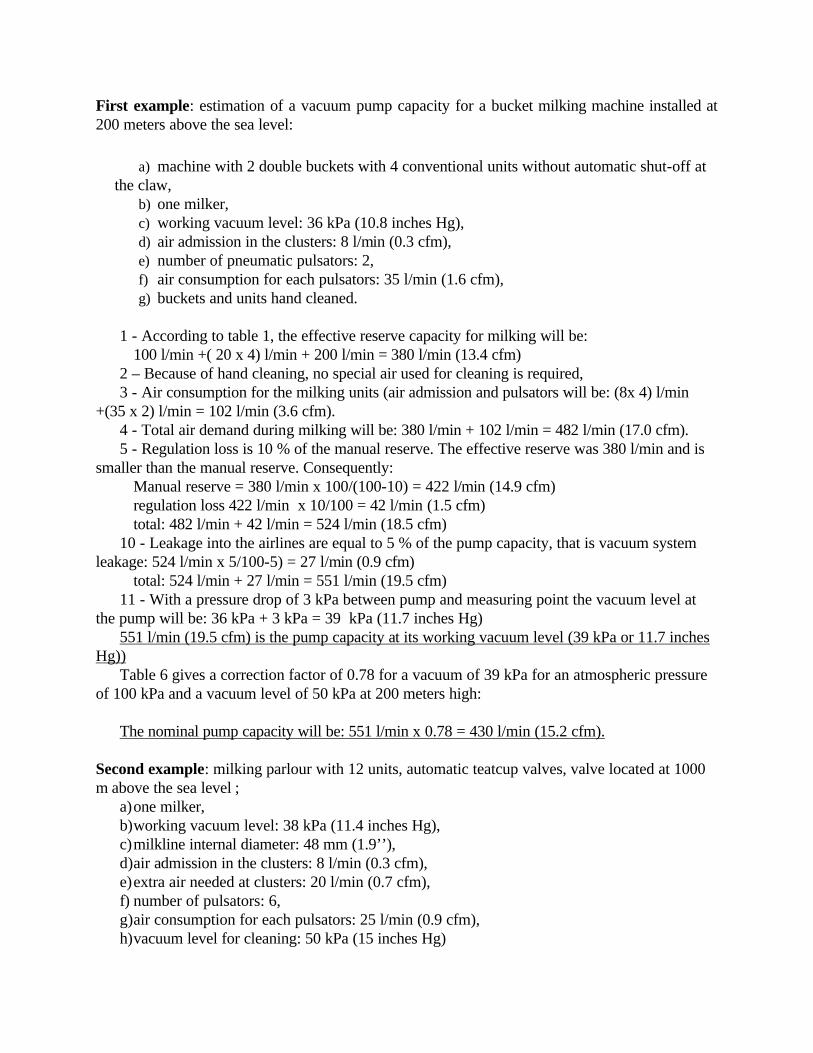
First example: estimation of a vacuum pump capacity for a bucket milking machine installed at 200 meters above the sea level:
a) machine with 2 double buckets with 4 conventional units without automatic shut-off at the claw,
b) one milker, c) working vacuum level: 36 kPa (10.8 inches Hg), d) air admission in the clusters: 8 l/min (0.3 cfm), e) number of pneumatic pulsators: 2, f) air consumption for each pulsators: 35 l/min (1.6 cfm), g) buckets and units hand cleaned.
1 - According to table 1, the effective reserve capacity for milking will be: 100 l/min +( 20 x 4) l/min + 200 l/min = 380 l/min (13.4 cfm) 2 – Because of hand cleaning, no special air used for cleaning is required, 3 - Air consumption for the milking units (air admission and pulsators will be: (8x 4) l/min
+(35 x 2) l/min = 102 l/min (3.6 cfm). 4 - Total air demand during milking will be: 380 l/min + 102 l/min = 482 l/min (17.0 cfm). 5 - Regulation loss is 10 % of the manual reserve. The effective reserve was 380 l/min and is
smaller than the manual reserve. Consequently: Manual reserve = 380 l/min x 100/(100-10) = 422 l/min (14.9 cfm) regulation loss 422 l/min x 10/100 = 42 l/min (1.5 cfm) total: 482 l/min + 42 l/min = 524 l/min (18.5 cfm) 10 - Leakage into the airlines are equal to 5 % of the pump capacity, that is vacuum system
leakage: 524 l/min x 5/100-5) = 27 l/min (0.9 cfm) total: 524 l/min + 27 l/min = 551 l/min (19.5 cfm) 11 - With a pressure drop of 3 kPa between pump and measuring point the vacuum level at
the pump will be: 36 kPa + 3 kPa = 39 kPa (11.7 inches Hg) 551 l/min (19.5 cfm) is the pump capacity at its working vacuum level (39 kPa or 11.7 inches
Hg)) Table 6 gives a correction factor of 0.78 for a vacuum of 39 kPa for an atmospheric pressure
of 100 kPa and a vacuum level of 50 kPa at 200 meters high: The nominal pump capacity will be: 551 l/min x 0.78 = 430 l/min (15.2 cfm).
Second example: milking parlour with 12 units, automatic teatcup valves, valve located at 1000 m above the sea level ;
a) one milker, b) working vacuum level: 38 kPa (11.4 inches Hg), c) milkline internal diameter: 48 mm (1.9’’), d) air admission in the clusters: 8 l/min (0.3 cfm), e) extra air needed at clusters: 20 l/min (0.7 cfm), f) number of pulsators: 6, g) air consumption for each pulsators: 25 l/min (0.9 cfm), h) vacuum level for cleaning: 50 kPa (15 inches Hg)

1 - According to table 1 the effective reserve capacity for milking will be: 400 l/min +( 10 x 2) l/min + (12 x 20) l/min = 660 l/min (23.3 cfm) 2 - According to table 7 the air demand for cleaning at 50 kPa for a milkline of 48 mm internal diameter and at an altitude of 1000 m should be 386 l/min (13.6 cfm) which is lower than the effective reserve for milking 3 - Air consumption for the milking units (air admission and pulsators will be: (8x 12) l/min +(25 x 6) l/min = 246 l/min (8.7 cfm) 4 - Total air demand during milking will be: 660 l/min + 246 l/min = 906 l/min (32.0 cfm) 5 - Total air demand during cleaning will be: 434 l/min + 246 l/min = 680 l/min (24.0 cfm) 6 - In this example the capacity for milking is larger and therefore shall be taken as a basis for the pump dimensioning. 7 - Leakage into the milk system: 10 l/min + (2 x 12) l/min = 34 l/min (1.2 cfm) 8 - Total: 906 l/min + 34 l/min = 940 l/min (33.2 cfm) 9 - Regulation loss is 10 % of the manual reserve. The effective reserve was 660 l/min (23.3 cfm)and is smaller than the manual reserve. Consequently: Manual reserve = 660 l/min x 100/(100-10) = 733 l/min (25.9 cfm) regulation loss 733 l/min ; x 10/100 = 73 l/min (2.6 cfm) total: 940 l/min + 73 l/min = 1013 l/min (35.8 cfm). 10 - Leakage into the airlines are equal to 5 % of the pump capacity, that is vacuum system leakage: 1013 l/min x 5/100-5) = 53 l/min (1.9 cfm) total: 1013 l/min + 53 l/min = 1066 l/min (37.7 cfm) 11 - With a pressure drop of 3 kPa between pump and measuring point the vacuum level at the pump will be: 38 kPa + 3 kPa = 41 kPa (12.3 inches Hg). 1066 l/min (37.7 cfm) is the vacuum pump capacity at its working vacuum,
Correction for the higher altitude in accordance with table 6 for the altitude of 1000 m and a vacuum of 41 kPa will give a correction factor of 0.90 for an atmospheric pressure of 100 kPa and a vacuum level of 50 kPa. The nominal pump capacity is: 1066 l/min x 0.9 = 959l/min (33.9 cfm)
Regulation
The regulator is one of the main parts of a milking machine. Its role is to keep the vacuum level constant within the range of 2 kPa during the course of normal milking, including teatcup attachment and removal, liner slips or teatcups falls-off for at least 99% of the milking time.
Self controlled regulators are good devices and easily fulfil the requirements. They only have
to be maintained in good order by good maintenance. A regulator has to be sensitive (<1 kPa). Sensitivity of the regulator is the difference of
working vacuum when the machine is working with no milking unit connected, and all units
connected. A lower sensitivity can lead to a higher and/or unstable working vacuum which has bad effects on udder health and teat end conditions.
A high regulation loss (air flow through the regulator when it normally would be closed)
indicates some problems of connection or leakages between the regulator and the receiver. This issue leads to higher irregular fluctuations in the long milk tube as shown on figure 5.
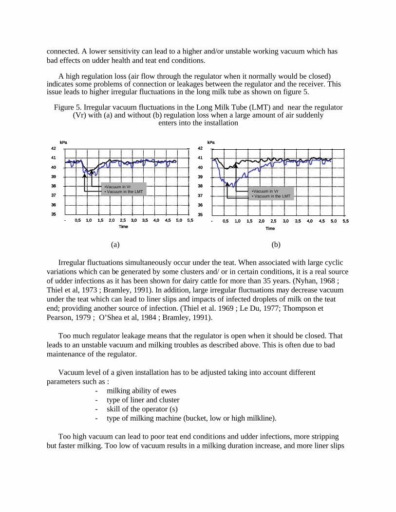
Figure 5. Irregular vacuum fluctuations in the Long Milk Tube (LMT) and near the regulator (Vr) with (a) and without (b) regulation loss when a large amount of air suddenly
enters into the installation
(a) (b)
Irregular fluctuations simultaneously occur under the teat. When associated with large cyclic variations which can be generated by some clusters and/ or in certain conditions, it is a real source of udder infections as it has been shown for dairy cattle for more than 35 years. (Nyhan, 1968 ; Thiel et al, 1973 ; Bramley, 1991). In addition, large irregular fluctuations may decrease vacuum under the teat which can lead to liner slips and impacts of infected droplets of milk on the teat end; providing another source of infection. (Thiel et al. 1969 ; Le Du, 1977; Thompson et Pearson, 1979 ; O’Shea et al, 1984 ; Bramley, 1991).
Too much regulator leakage means that the regulator is open when it should be closed. That
leads to an unstable vacuum and milking troubles as described above. This is often due to bad maintenance of the regulator.
Vacuum level of a given installation has to be adjusted taking into account different
parameters such as : - milking ability of ewes - type of liner and cluster - skill of the operator (s) - type of milking machine (bucket, low or high milkline).
Too high vacuum can lead to poor teat end conditions and udder infections, more stripping
but faster milking. Too low of vacuum results in a milking duration increase, and more liner slips
35
36
37
38
39
40
41
42
- 0,5 1,0 1,5 2,0 2,5 3,0 3,5 4,0 4,5 5,0 5,5
Time
•Vacuum in Vr• Vacuum in the LMT
kPa
Time
35
36
37
38
39
40
41
42
- 0,5 1,0 1,5 2,0 2,5 3,0 3,5 4,0 4,5 5,0 5,5
•Vacuum in Vr• Vacuum in the LMT
kPa
35
36
37
38
39
40
41
42
- 0,5 1,0 1,5 2,0 2,5 3,0 3,5 4,0 4,5 5,0 5,5
Time
•Vacuum in Vr• Vacuum in the LMT
kPa
35
36
37
38
39
40
41
42
- 0,5 1,0 1,5 2,0 2,5 3,0 3,5 4,0 4,5 5,0 5,5
Time
•Vacuum in Vr• Vacuum in the LMT
kPa
Time
35
36
37
38
39
40
41
42
- 0,5 1,0 1,5 2,0 2,5 3,0 3,5 4,0 4,5 5,0 5,5
•Vacuum in Vr• Vacuum in the LMT
kPa
Time
35
36
37
38
39
40
41
42
- 0,5 1,0 1,5 2,0 2,5 3,0 3,5 4,0 4,5 5,0 5,5
•Vacuum in Vr• Vacuum in the LMT
kPa

and fall-offs can be observed. Then, it is easy to understand that the best vacuum for a given installation is a compromise between all these parameters.
Usually, the following vacuum levels are advised:
34-38 kPa (10.2-11.4 inches Hg) for buckets and low milklines 38-40 kPa (11.4-12 inches Hg) for high line milklines. Pulsation System
Type of pulsators 2 types of pulsators are used : pneumatic and electronic. Pneumatic pulsators are traditionally used in very small plants with buckets, for example. They
are very simple devices only working with vacuum. However, their characteristics, especially pulsation rate, are vacuum sensitive. For example if the regulator fails or if the farmer wants to change the working vacuum, pulsation rate will also change. Pulsator ratio is also affected but in a smaller proportion.
The main drawback of pneumatic pulsators is a tendency for failure due to worn pieces and
moisture. A French study (Sauvée et al, 1998) showed that less than three months after having being checked and adjusted, more than half of them were still out of order. That means that pneumatic pulsators have to be checked very often (every month for example) and maintained in a good order by at least cleaning filters and changing worn components. The risk of failure increases when feeding ewes during milking due to dust generated by concentrate foodstuffs falling down into mangers. In this case, cleaning and maintenance have to be reinforced.
Electronic pulsators are now used in milking parlours. They have two main components: a
pulsation generator which is an electric and electronic device that sends electric signals to an electric relay or a pulsator. Generally, in dairy sheep milking machines, one relay or pulsator is used for two units. Electronic pulsators are more reliable because pulsation rate doesn’t change with vacuum and is stable. Obviously, pulsator ratio can also fail if relays are not clean enough. However, the above mentioned French study showed that most electronic pulsators were still working well 18 months after their last adjustment. Unfortunately, they are more expensive, but they lead to more relaxed milking conditions both for milkers and animals.
So, it is recommended to use electronic pulsation instead of a pneumatic one, especially in
milking parlours. In dairy sheep milking machines, pulsators used are simultaneous pulsators. That means that
each half udder is at the same time in the suckling phase and in the rest phase (figure 6).

Figure 6. Different phases of the pulsation curve
Recent researches (Billon et al., 2004) showed that there are no technical reasons for using
alternate pulsation for dairy ewes with modern clusters and liners (similar average, minimum and maximum teat end vacuum and similar movement of the liner) (figure 7). The only reason for choosing alternate pulsation in dairy sheep milking machines should be when using very small clusters with small internal diameter of the short milk tubes in order to avoid claw flooding by dividing the milk flow rate by 2.
Figure 7. Vacuum under the teat and in the claw, and movements of the liner at simultaneous and
alternative pulsation in a modern cluster in low line. (1.5 l/min liquid flow rate at 36 kPa (10.8 inches Hg).
In milking parlours, it is recommended that filtered atmospheric air be used for the pulsators
in order to maintain clean relays for the longest time as possible. The air filter should be installed
Time
a b c d
Vac
uum
Suckling phase
Rest phase
Time
a b c d
Vac
uum
Suckling phase
Rest phase
0
10
20
30
40
-4.04 -3.79 -3.54 -3.29 -3.04 -2.79 -2.54 -2.29
Time (s)
Vac
uum
(kP
a)
Alt pulsation (kPa) Sim pulsation (kPa) Teat alt (kPa)
Teat sim (kPa) Liner Mvts alt (mm) Liner Mvts sim (mm)

in a place where it cannot be contaminated with dust coming from forage or other goods that can taint dairy products.
Pulsation rate A survey carried out by the International Dairy federation (I.D.F.) in 1998 showed that
pulsation rate for dairy sheep is usually in the range from 90 to 180 cycles/min. A lot of studies showed that a high pulsation rate is necessary to obtain the most milk during the shortest milking time. For example, Le Du (1981) showed that a pulsation rate of 180 cycles/min leads to a shorter machine on time, more fat content, similar machine yield and more total milk due to more stripping milk and obviously greater stripping time. However, this study was carried out at a 44 kPa vacuum level in high line parlour; it is likely the main cause of a higher level of stripping.
French field experiences confirm everyday that a high pulsation rate leads to better milking
conditions and not necessarily to a higher amount of stripping milk which depends both on the shape of the udder and on the teats location on the udder.
In addition, a fast pulsation rate leads to better teat end conditions (Marnet et al., 2002) (figure
8).
Figure 8. Relationship between teat end conditions and pulsation rate and working vacuum level
More recent field observations in France on different breeds showed that pulsation rate should not be less than 150 cycles per minute. 180 cycles/min should be the pulsation rate for high yielding ewes such as the Lacaune breed.
When checking, the pulsation rate must not deviate by more than 5 % from the values given by the installer. It is easy to check the pulsation rate with the thumb into the mouthpiece chamber
5060708090
100110120
180 Cycles/min - 36 kPa
180 Cycles/min - 44 kPa
120 Cycles/min - 40 kPa
60 Cycles/min - 36 kPa
60 Cycles/min - 44 kPa
treatment
% te
at d
econ
gest
ion

during half a minute or one minute. If the number of massages during one minute shows a higher deviation than 5% from the initial value, the pulsators must, at least, be cleaned. If no amelioration occurs after cleaning, the pulsators must be checked by the dealer.
Pulsator ratio Traditionally, pulsator ratio used in milking machines for sheep is 50%. A pulsator ratio of
60% is possible. In certain cases a higher ratio improves the pulsation curve and movements of the liner, especially when the liner is open leading to a quicker milking.
When checking, the pulsator ratio must not differ more than ± 5 units of percentage from the
values given by the installer. In addition, pulsator ratios of all pulsators of an installation must not vary from each other by more than 5 units of percentage, and, in case of alternate pulsation, the two teatcups may not vary from each other by more than 5 %.
Because it is more difficult to check the ratio without special tools and recording devices, it is
recommended that the dealer check every pulsator at least once a year and more often for pneumatic devices.
Pulsation phases Right now, there is no evidence, and no scientific proof, of effects of pulsation phases on
milking and udder health for dairy sheep. More research is needed. Milk System
Minimum internal diameter of milklines Ideally in a milkline, milk should flow in the lower part of the pipeline with a clear continuous
space above for the much larger volume of air to pass over it. This flow condition is known as stratified flow. In practice, flow typically varies between stratified flow and slug flow. Slug flow occurs whenever slugs of milk fill the entire cross-section of the milkline. Slug flow conditions in the milkline almost always induce transient vacuum drops greater than 2 kPa. Chronic slugging in the milkline is likely to have almost the same effect on milking performance and milk quality as raising the milkline height by about 300 mm to 500 mm, i.e., slower milking and more liner slips (because of lower minimum liner vacuum), and higher acid degree values. Milkline vacuum almost always remains stable within ± 2 kPa of the receiver vacuum under stratified flow conditions. Therefore, the limit of 2 kPa essentially means that stratified flow should be the normal flow condition in the milkline.
Experimental laboratory studies have been carried out to determine the maximum milk flow
rate to ensure that stratified flow is the normal flow condition during dairy cattle milking. There is apparently no reason why equations figured for cattle should not apply to small ruminants if the ratio between steady air flow and milk flow is chosen according to real milking conditions of these

species. For example, with dairy cattle, the experimental data were based on a ratio of 10 l/min (0.35 cfm) steady air flow at the unit per 4.5 l/min liquid per unit, i.e. a ratio of 2.2.
However, the problem is more difficult with small ruminants because maximum flow rate can
vary between between breeds. Thus, it is suggested that equations referring to dairy cattle (ISO 5707) for three different ratios based on 8 l/min (0.28 cfm) steady air per unit ( refer to the paragraph related to air vent and leakage at the unit) and three milk flow rates apply: 0.8 l/min for species and breeds with low maximum milk flow rates (Lacaune and Manech breeds for example), 1.3 l/min for species and breeds with medium maximum milk flow rates (Manchega, Churra and Laxta breeds for example), and 2.7 l/min for species and breeds with high maximum milk flow rates (Sardinian breed for example). Referring to the results of McKusick et al. (2002), a milk ejection curve for East Friesian ewes in Wisconsin is similar to the one for medium maximum milk flow rate such as Manchega, Chura or Laxta breeds (average parameters: maximum flow rate - 1.24 l/min, milk flow latency - 13.1 seconds, machine milking time - 105.9 seconds) (figure 9).
Figure 9. Typical milk flow rate curves for sheep
Maximum milk flow in the milkline can be predicted from the milk flow curves taking into account the breed and the average attachment rate. Then it is possible to figure the maximum milk flow per slope to ensure that stratified flow is the normal condition during milking. The calculated milk flow must be less (or at least equal) to the predicted milk flow in the milkline.
Tables 8 shows examples of the predicted maximum milk flow rate of a group of sheep with maximum milk flow rates of 0.8 and 1.3 l/min and for units attached at intervals of 5 and 10 seconds which are common milking routines for small ruminants.
0.000
0.500
1.000
1.500
2.000
2.500
3.000
0 25 50 75 100 125
time (s)
Max
flow
rate
(l/m
in.)
dmax=0.8 l/min dmax=1.3 l/min dmax=2.7 l/min

Table 8: Maximum predicted milk flow rate in litres/minute in milklines for sheep
No units 6 10 12 16 Attcht rate (s) Maximum flow rate : 0.8 l/min 5 4.8 7.3 8.2 9.0 10 4.1 4.6 4.6 4.6 Maximum flow rate : 1.3 l/min 5 7.1 9.1 9.6 10.0 10 4.9 5.2 5.2 5.2
The main parameters for sizing milklines are the following :
- type of cluster and transient air when handling for each kind of cluster, - slope of the milkline, - configuration of the milkline (looped or dead-ended), - attachment rate, - maximum predicted milk flow rate.
The designed air flow conditions are based on a steady air admission of 8 l/min (0.3 cfm)
through air vents and constant leaks at the cluster, plus intermittent air flows associated with attachment, liner slips and removal.
The proposed guidelines for transient air must be consistent with the other requirements and
particularly with the ER calculation and are the following: 1- for conventional clusters without automatic shut-off valve: 400 l/min (14.1 cfm) for
intermittent air flow into a dead-ended line, or 200 l/min (7.1 cfm) per slope for a looped milk line 2- for conventional clusters with automatic shut-off valve: 200 l/min (7.1 cfm) for intermittent
air flow into a dead-ended line, or 100 l/min (3.5 cfm) per slope for a looped milk line 3- for non-conventional clusters (with automatic teatcup valves): 50 l/min ( 1.8 cfm) for
intermittent air flow into a dead-ended line, or 25 l/min (0.9 cfm) per slope for a looped milk line A special Excel sheet was made in order to facilitate calculations. See example below (figure
10).

Figure 10. Milklines sizing
Table 9 gives an example of the maximal number of units per slope for East Friesian ewes
(dmax = 1.3 l/min) and a milkline of 48.5 mm (2’’) internal diameter at an attachment rate of 5 s. Table 9: Maximal number of units per slope for ewes with dmax = 1.3 l/min and a milkline of 48.5
mm (2’’) internal diameter and an interval attachment of 5 s. Type of Cluster Looped milklines (dead-ended milklines)
slope (%)
0.5 1.0 1.5 2.0 Conventional without
automatic shut-off 3 (2) 9 (3) * (7) * (*) Conventional with automatic
shut-off 5 (3) * (9) * (*) * (*) Non conventional with
automatic teatcups valves 4 (*) 9 (*) * (*) * (*) * = unlimited number of milking units
For other calculations (i.e. different attachment rates, other diameters,…), use the Excel sheet.
Race : Débit maximal par animal 1.3 l/mn
Nombre de postes par ramification Durée de traite : < 120 s
Rythme de pose des faisceaux trayeurs Débit maximal de lait pendant la traite 4.6 l/mn
Type de faisceau trayeur
Diamètre du lactoduc Pente minimale possible : 0.8%
Type de lactoduc Pente conseillée 1.0%
Débit maximal de lait permis par le lactoduc 5.5 l/mn
Ce choix est possible
Calcul du diamètre des lactoducs pour installation de traite pour brebis
RésultatsChoix des paramètres de calcul
Manchega
5
10
Conventionnel sans clapet
48.5
Non bouclé
ImpressionNouveau
calculChanger d'espèce

Cluster Assembly
Long milk tube The long milk tube can have a large effect on vacuum fluctuations under the teat. To minimize
this issue, its internal diameter must be greater than 12.5 mm (or at least equal). When using a high level milkline, and because of the column of milk to be lifted from the claw to the milkline, the internal diameter of the long milk tube shall be less than 14.5 mm (or at least equal).
When using low level milkline, length of the long milk tube must be as short as possible
without a bend in order to avoid milk being lifted into the milkline.
Short milk tube
To reduce the likelihood of milk plugs in the short milk tube and reverse flow and/or impacts against the teat, it is recommended to use a short milk tube with internal diameter of at least 9 mm.
Claw Clusters used in milking machines for sheep have a claw of 50-100 cc, but some of them are
only made with tubes of stainless steel, or plastic, as a Y shape. This kind of claw can milk ewes while maintaining desired vacuum only if the internal diameter of the short milk tubes (SMT) is at least 9 mm and if the air vent is in good order. Then the bowl is not necessary.
Conventional clusters can be equipped with an automatic shut-off device at the claw. With
such a device, it is easier for the operator to limit air entering into the installation during detachments and when going from one animal to another. It also shuts off the vacuum when the cluster falls off onto the platform. Obviously, it leads to less air into the plant and less bacteria in the milk. At least, an easy-to-use clamp should be installed on the long milk tube.
Air vent and leakage An air vent at the cluster is necessary in order to avoid flooded claws and/or slugs in short
milk tubes. With clusters including a liner with an elbow and a long short milk tube (25 up to 30 cm -10 to 12 inches-), it is recommended to locate the air vent at each teatcup just above or at the elbow leads for a better milking, better draining of tubes and claws (Le Du, 1981) (table 10) and less vacuum fluctuations under teats.

Table 10. Influence of the place of air vent on milking Air vent Total
Milk Stripping milk
Machine Milking time
Average flow rate
At the claw 756 94.5 91 436.1 At the claw AND at the bend 771 84.1 85.1 484.3 Stat NS ** * *
The total air intake per cluster from the air vent and air leakage (conventional clusters) must
not exceed 8 l/min (0.28 cfm) and must allow at least 4 l/min of free air ( 0.14 cfm) at the nominal working vacuum level. That means that a constant effort of the operator has to be done in order to maintain the air vent free of dust and moisture.
In conventional clusters, a maximum of 2 l/min at the shut-off device is tolerated.
Liner The liner is one of the most important components of a milking machine, yet this is relatively
unknown. The main characteristics of a liner should be the following: - quick and gently milking of every animals, - limiting stripping, - limiting liner slips and avoiding fall-off, - limited influence on somatic cells count (SCC) and clinical mastitis, - limited influence on free fatty acids (FFA).
Le Du (1981) showed that liners made of silicone produced the same amount of stripping milk
compared with liners made with rubber. Another study by the same author compared 4 liners, the characteristics of which are shown in table 11. This study was performed on Lacaune ewes with a lowline milking machine working at 36 kPa (10.8 inches Hg), a pulsation rate of 172 cycles/min, and a pulsator ratio of 50%.
Table 11. Characteristics of studied liners Liner Parameter
Ref A B C
Mouthpiece lip ID (mm) 20 22 15 20 Barrel ID (mm) (top) 19 19 20 21 Barrel ID (mm) (bottom) 19 19 16 21 Buckling pressure (kPa) 10.7 10 10 4.7
Results show that for Lacaune ewes, and likely for ewes with similar milking ability and udder
and teats morphology, a good liner has a mouthpiece lip diameter not greater than 19 mm, a tapered and smooth barrel (table 12). The lowest amount of milk during stripping was obtained with two different liners, one with a tapered barrel and the other with a larger bore. That is consistent with other studies carried out on cows. Machine-on time was the lowest when the liner bore was not too high (around 19 mm) or tapered. Liner B gave the best compromise between all
requirements and objectives mentioned earlier. In addition, the better teat end conditions after the 48 days of experimentation lead to the conclusion that a soft liner with a low buckling pressure (7-8 kPa) is likely interesting. However, too low buckling pressure as liner C in the experiment seems to indicate too weak of material because early distorted mouthpiece lips were observed.
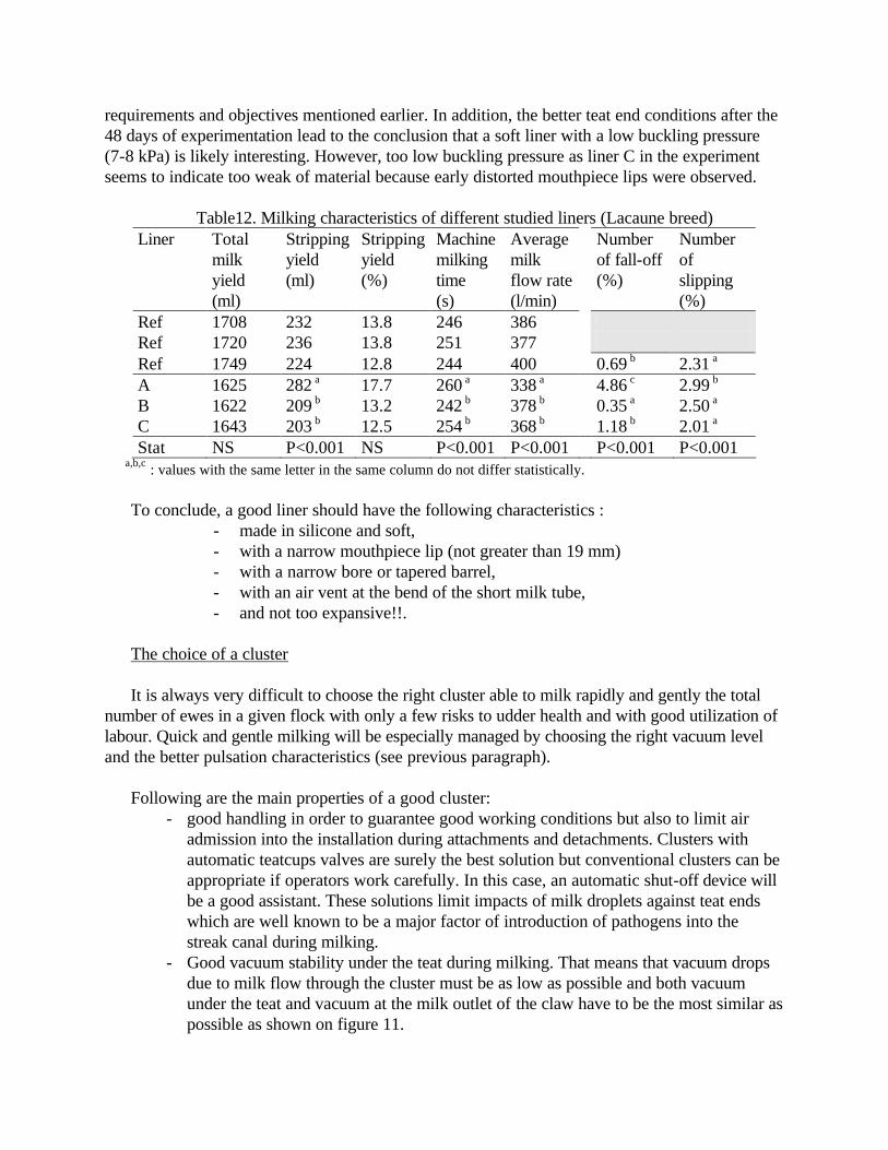
Table12. Milking characteristics of different studied liners (Lacaune breed)
Liner Total milk yield (ml)
Stripping yield (ml)
Stripping yield (%)
Machine milking time (s)
Average milk flow rate (l/min)
Number of fall-off (%)
Number of slipping (%)
Ref 1708 232 13.8 246 386 Ref 1720 236 13.8 251 377 Ref 1749 224 12.8 244 400 0.69 b 2.31 a A 1625 282 a 17.7 260 a 338 a 4.86 c 2.99 b B 1622 209 b 13.2 242 b 378 b 0.35 a 2.50 a C 1643 203 b 12.5 254 b 368 b 1.18 b 2.01 a Stat NS P<0.001 NS P<0.001 P<0.001 P<0.001 P<0.001
a,b,c : values with the same letter in the same column do not differ statistically. To conclude, a good liner should have the following characteristics :
- made in silicone and soft, - with a narrow mouthpiece lip (not greater than 19 mm) - with a narrow bore or tapered barrel, - with an air vent at the bend of the short milk tube, - and not too expansive!!.
The choice of a cluster It is always very difficult to choose the right cluster able to milk rapidly and gently the total
number of ewes in a given flock with only a few risks to udder health and with good utilization of labour. Quick and gentle milking will be especially managed by choosing the right vacuum level and the better pulsation characteristics (see previous paragraph).
Following are the main properties of a good cluster:
- good handling in order to guarantee good working conditions but also to limit air admission into the installation during attachments and detachments. Clusters with automatic teatcups valves are surely the best solution but conventional clusters can be appropriate if operators work carefully. In this case, an automatic shut-off device will be a good assistant. These solutions limit impacts of milk droplets against teat ends which are well known to be a major factor of introduction of pathogens into the streak canal during milking.
- Good vacuum stability under the teat during milking. That means that vacuum drops due to milk flow through the cluster must be as low as possible and both vacuum under the teat and vacuum at the milk outlet of the claw have to be the most similar as possible as shown on figure 11.
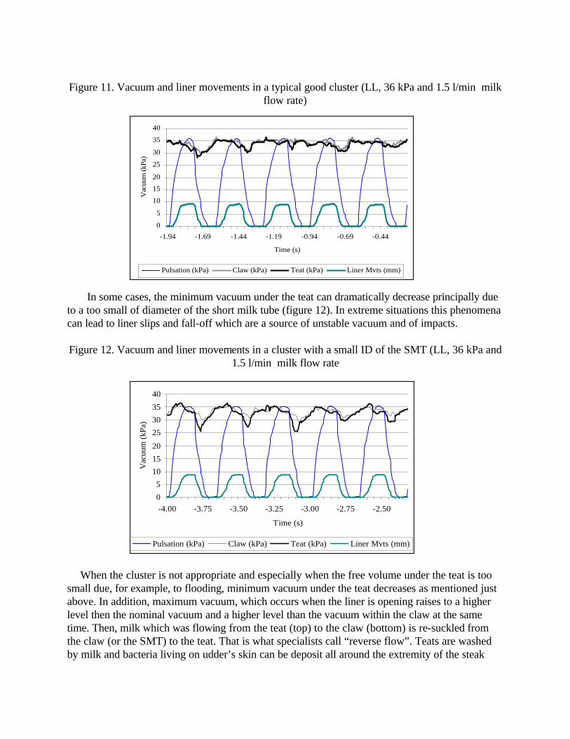
Figure 11. Vacuum and liner movements in a typical good cluster (LL, 36 kPa and 1.5 l/min milk
flow rate)
In some cases, the minimum vacuum under the teat can dramatically decrease principally due
to a too small of diameter of the short milk tube (figure 12). In extreme situations this phenomena can lead to liner slips and fall-off which are a source of unstable vacuum and of impacts. Figure 12. Vacuum and liner movements in a cluster with a small ID of the SMT (LL, 36 kPa and
1.5 l/min milk flow rate
When the cluster is not appropriate and especially when the free volume under the teat is too small due, for example, to flooding, minimum vacuum under the teat decreases as mentioned just above. In addition, maximum vacuum, which occurs when the liner is opening raises to a higher level then the nominal vacuum and a higher level than the vacuum within the claw at the same time. Then, milk which was flowing from the teat (top) to the claw (bottom) is re-suckled from the claw (or the SMT) to the teat. That is what specialists call “reverse flow”. Teats are washed by milk and bacteria living on udder’s skin can be deposit all around the extremity of the steak
0
5
10
15
20
25
30
35
40
-1.94 -1.69 -1.44 -1.19 -0.94 -0.69 -0.44
Time (s)
Vac
uum
(kPa
)
Pulsation (kPa) Claw (kPa) Teat (kPa) Liner Mvts (mm)
0
5
10
15
20
25
30
35
40
-4.00 -3.75 -3.50 -3.25 -3.00 -2.75 -2.50
Time (s)
Vac
uum
(kPa
)
Pulsation (kPa) Claw (kPa) Teat (kPa) Liner Mvts (mm)

canal, ready to be introduced during milking or at the end of milking just before the canal is completely closed (figure 13).
Figure 13. Vacuum and liner movements in two clusters with a flooded claw or SMT
(LL, 36 kPa and 1.5 l/min milk flow rate)
- In addition with dimensional aspects mentioned in the previous paragraph, movements of the liner are very important. Despite the high pulsation rate, we can observe a real ‘suckling’ phase when the liner is completely open and a real ‘rest’ phase with the liner is collapsed (see figures 11 to 13). Obviously, duration of these phases vary from liner to liner. Laboratory recordings with 8 different kinds of clusters, now used for sheep worldwide, showed that the duration of the ‘suckling’ phase varied from 62 up to 111 ms, and the duration of the ‘rest’ phase varied between 73 and 167 ms. That shows that for several liners the ‘rest’ phase is longer that the ‘suckling’ phase. More research is needed in order to define what should be the best duration.
- Finally, recent studies show that some clusters are less dependant than others on milk flow. Figures 14 show two examples of evolution of the average vacuum under the teat of two clusters in high and low milklines. When the average vacuum under the teat is practically constant, that means that every ewe can be milked at the same vacuum level at each moment of milking. Obviously, more research is also needed in order to ensure that constant vacuum conditions during milking of ewes are absolutely necessary.
Figure 14. Average vacuum under the teat in relationship with milk flow rate
0
10
20
30
40
-4.00 -3.75 -3.50 -3.25 -3.00 -2.75 -2.50
Time (s)
Vac
uum
(kP
a)
Pulsation (kPa) Claw (kPa) Teat (kPa) Liner Mvts (mm)
0
10
20
30
40
-2.51 -2.26 -2.01 -1.76 -1.51 -1.26 -1.01
Time (s)
Vac
uum
(kP
a)
Pulsation (kPa) Teat (kPa) Claw (kPa) liner Mvts (mm)

and type of milkline
Conclusion
A milking machine must be properly sized, taking into account both animals and operator(s). Each component of the machine is important, and all of them must perfectly work together in order to avoid milk quality issues and udder health troubles. The milker must not believe that the biggest is the best: for example, bigger vacuum pump or larger milkline internal diameter than needed are obviously more expensive when buying but also when working: higher energy, water and hygiene products consumption.
In addition, a bad operator will automatically lead to bad milking and bad results. Efforts
should be done by farmers in milking routine so that they try to limit overmilking, for example and for maintenance of the main components such as the vacuum pump, the regulator and pulsators. References Billon P., Ronningen O., Sangiorgi F. and Schuiling E., 1999. Quantitative requirements of milking installations for small ruminants. A survey in different countries. In Milking and milk production of dairy sheep and goats, pp 209-215. EAAP publication N° 95, 1999, Wageningen. Billon P., Fernandez Martinez, N., Ronningen O., Sangiorgi F., and Schuiling E., 2002. Quantitative requirements for Milking Installations for Small Ruminants. I.D.F. bulletin 370/2002. Billon P., Gaudin V., Maugras J., and Giraudeau L., 2004. Caractéristiques de fonctionnement de quelques faisceaux trayeurs pour brebis. Unpublished data. Bramley A.J.,1978. Some investigations on the effect of continuous vacuum on new infection of the udder In Proc. Int. Symp. Machine Milking. NMC. Arlington, VA.
26
28
30
32
34
36
38
0 0.5 1 1.5 2 2.5 3 3.5 4 4.5
Flow rate (l/min)
Vac
uum
(kPa
)
LL 34 kPa LL 36 kPa HL 36 kPa HL 38 kPa
26
28
30
32
34
36
38
0 0.5 1 1.5 2 2.5 3 3.5 4
Flow rate (l/min)
Vac
uum
(kPa
)
LL 34 kPa LL 36 kPa HL 36 kPa HL 38 kPa

Bramley A.J., 1991.Mastitis and Machine Milking In Machine Milking and lactation, 343-372. Le Du J., 1977. The milking machine : physical parameters characterizing the teat cup liner working conditions. Ann. Biol. Anim. Bioch. Biophys.., 17 (6), 971-985. Le Du J., 1981. La machine à traire les brebis : son incidence sur la traite. In : La production laitière dans les espèces ovine et caprine, 6° journées de la Recherche ovine et caprine, 2 et 3 décembre 1981, INRA ITOVIC, Paris, p 115-122. ISO 5707, 1996. Machines Milking Installations : construction and performances. 40 p. Marnet P.G., 2002. Ejection du lait chez les petits ruminants: implication pour la traite mécanique. Document de formation de l’Institut de l'Elevage, Avril 2002, 38p. Nyhan J.F., 1968. The effect of vacuum fluctuation on udder disease In Proc. Symp. Machine Milking - NIRD - Reading - England. p 71-82 O’Shea J., O’Callaghan U, Meaney W.J., 1983. Milking performance and liner design and slips. Proc. Annual. Meet. National Mastitis Council, Louisville, KY, 22 4-14. Sauvée O., Billon, P., Gaudin V. and Poirier S., 1998. Contrôle des installations de traite : état du parc contrôlé, recherche d’un intervalle optimum entre deux contrôles. In Proceedings 5ièmes Rencontres Recherches Ruminants, 2-3 décembre 1998, Paris, p 327-330. Thiel CC, Thomas CL, Westgarth D.R and Reiter B., 1969. Impact force as a possible cause of mechanical transfer of bacteria. Journal of Dairy Research, 36, 279-298. Thiel C.C., Cousins C.L, Westgarth D R and Neave F.F,1973. The influence of some physical characteristics of the milking machine on the rate of new mastitis infections. Journal of Dairy Research n° 117-129. Thompson P.D. and Pearson RE., 1979. Likelihood of droplet impacts on teat ends during induced milking vacuum fluctuations. Journal of Dairy Science, 62, 13 14-1321.