the development of filler metal alloys … development of filler metal alloys for vacuum brazing-gas...
TRANSCRIPT
A&-T34 357
RIA-76-U102 AD
THE DEVELOPMENT OF FILLER METAL ALLOYS FOR VACUUM BRAZING-GAS QUENCHING
OF ALUMINUM ALLOYS
USADACS Technical Library
5 0712 01014407 8
FINAL REPORT
by
William J. Werner
Gerry M. Slaughter
November 1971 TECHNICAL LIBRARY
DEPARTMENT OF THE ARMY EDGEWOOD ARSENAL
Technical Support Directorate Industrial Operations Division
Edgewood Arsenal, Maryland 21010
DELIVERY ORDER NO. DAAA15-69-F-4895
U.S. ATOMIC ENERGY COMMISSION OAK RIDGE NATIONAL LABORATORY
Operated by
UNION CARBIDE CORPORATION, NUCLEAR DIVISION Post Office Box X
Oak Ridge, Tennessee 37830
Distribution Statement
Approved for public release; distribution unlimited.
Disclaimer
The findings in this report are not to be construed as an Official Department of the Army position unless so designated by other authorized documents.
Disposition
Destroy this report when no longer needed. Do not return it to the originator.
THE DEVELOPMENT OF FILLER METAL ALLOYS FOR VACUUM BRAZING-GAS QUENCHING OF ALUMINUM ALLOYS
FINAL REPORT
by
William J. Werner Gerry M. Slaughter
November 1971
Approved for public release; distribution unlimited.
DEPARTMENT OF THE ARMY EDGEWOOD ARSENAL
Technical Support Directorate Industrial Operations Division
Edgewood Arsenal, Maryland 21010
Delivery Order No. DAAA15-69-F-4895
U.S. ATOMIC ENERGY COMMISSION OAK RIDGE NATIONAL LABORATORY
Operated by UNION CARBIDE CORPORATION, NUCLEAR DIVISION
Post Office Box X Oak Ridge, Tennessee 37830
FOREWORD
The work described in this report was authorized under PEMA 4930.10.51129 (5671129), Vacuum Brazing-Gas Quenching of Chemical and Related Munitions. The program was started in April 1969 and concluded in December 1970.
Reproduction of this document in whole or in part is prohibited except with permission of Commanding Officer, Edgewood Arsenal, ATTN: SMUEA-TSIO, Edgewood Arsenal, Maryland 21010; however, DDC and the National Technical Information Service are authorized to reproduce this document.
Acknowledgements
The authors wish to express their appreciation to all of the personnel of the Metals and Ceramic Division, Oak Ridge National Laboratory, who were instrumental in carrying out the work of this program. My special appreciation to Mr. James Wier, Oak Ridge National Laboratory, and Mr. Louis Garono, P.E., Chief Engineer, Edgewood Arsenal, Maryland. The work was sponsored by PEMA, Manufacturing Methods and Technology Programs and monitored by the Contract Project Officer, Edgewood Arsenal, Maryland.
DIGEST
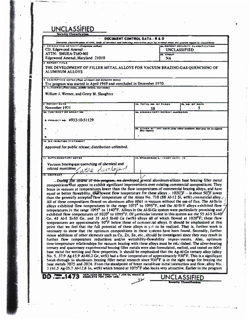
During the course of this program, we developed several aluminum-silicon base brazing filler metal compositions that appear to exhibit significant improvements over existing commercial compositions. They braze in vacuum at temperatures lower than the flow temperatures of commercial brazing alloys, and have equal or better flowability. Our lowest flow temperature for these alloys — 1020°F - is about 50°F lower than the generally accepted flow temperature of the Alcoa No. 718 (88 Al-12 Si, wt%) commercial alloy. All of these compositions flowed on aluminum alloy 6061 in vacuum without the use of flux. The Al-Si-In alloys exhibited flow temperatures in the range 1075° to 1095°F, and the Al-Si-Y alloys exhibited flow temperatures in the range 1095° to 1140°F. Alloys in the Al-Si-Ge system were particularly promising and exhibited flow temperatures of 1020° to 1095°F. Of particular interest in this system are the 55 Al-5 Si-40 Ge, 45 Al-5 Si-50 Ge, and 35 Al-5 Si-60 Ge (wt%) alloys all of which flowed at 1020°F; these now temperatures are approximately 50°F below those of commercial alloys.
It should be emphasized at this point that we feel that the full potential of these alloys is yet to be realized. That is, further work is necessary to show that the optimum compositions in these systems have been found. Secondly, further minor additions of other elements such as Cu, Zn, Sn, etc., should be investigated since they may result in further flow temperature reductions and/or wettability-flowability improvements. Also, optimum time-temperature relationships for vacuum brazing with these alloys must be established.
The silver-bearing ternary and quaternary experimental brazing filler metals were also formulated, melted, and tested on 6061 base metal for wetting and flow properties. It should be emphasized that the Ag-Al-Ge ternary alloy (alloy No. 5, 37.9 Ag-15.9 Al-46.2 Ge, wt%) had a flow temperature of approximately 930°F. This is a significant break-through in aluminum brazing filler metal research since 930°F is in the right range for brazing the base metals 7075 and 2024. From the standpoint of braze metal-base metal interaction and flow, alloy No. 1 (61.5 Ag-25.7 Al-12.8 In, wt%) which brazed at 1075°F also looks very attractive.
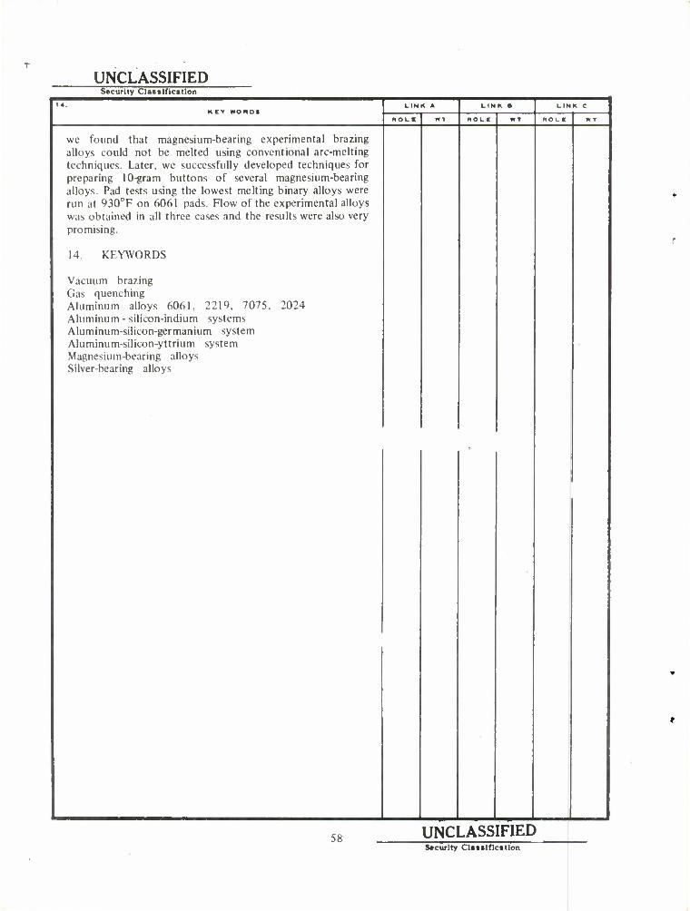
Earlier in the program we found that magnesium-bearing experimental brazing alloys could not be melted using conventional arc-melting techniques. Later, we successfully developed techniques for preparing 10-gram buttons of several magnesium-bearing alloys. Pad tests using the lowest melting binary alloys were run at 930°F on 6061 pads. Flow of the experimental alloys was obtained in all three cases and the results were also very promising.

CONTENTS
Page
I. INTRODUCTION
II. LITERATURE SURVEY 7
III. EQUIPMENT AND EXPERIMENTAL PROCEDURES 9
IV. FORMULATIONS OF EXPERIMENTAL BRAZING FILLER METAL COMPOSITIONS 14
A. Aluminum-Silicon-Indium System 14 B. Aluminum-Silicon-Germanium System 25 C. Aluminum-Silicon-Yttrium System 27 D. Silver-Bearing Alloys 27 E. Magnesium-Bearing Alloys 38 F. Additional Alloys Formulated and Melted in Al-Si-In and Al-Si-Ge
Systems 42
V. SUMMARY AND CONCLUSION 42
APPENDIX 45
DISTRIBUTION LIST 51
LIST OF TABLES
Table
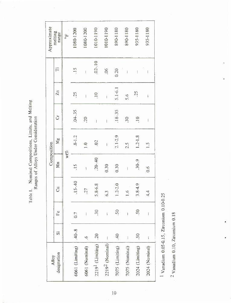
1 Nominal Compositions, Limits, and Melting Ranges of Alloys Under Consideration 10
II List of Potentially Compatible Elements for Brazing Filler Metal Alloy Formulation Supplied by Edgewood Arsenal 15
III Flow Temperatures and Compositions of the Al-Si-In Alloys 21
IV Flow Temperatures and Compositions of the Al-Si-Ge Alloys 25
V Flow Temperatures and Compositions of the Al-Si-Y Alloys 34
VI Composition and Flow Temperatures of Silver-Bearing Experimental Brazing Alloys 37
VII Compositions of Magnesium-Bearing Eutectic Alloys and Their Respective Eutectic Temperatures 38
VIII Compositions (wt%) of Additional Alloys Formulated and Melted in the Al-Si-In and Al-Si-Ge Systems 43
Figure
LIST OF FIGURES
(Y-95339) Apparatus for Determining Flow Temperatures and Wettability of Experimental Brazing Filler Metals 11
LIST OF FIGURES (Contd)
Figure ' Page
2 Time-temperature Response for Experimental Brazing Furnace 13
3 Ternary Plot of the Al-Si-In System with Attached Binary Phase Diagrams for the Estimation of Compositions of Potential Interest to the Program 17
4 Ternary Plot of the Al-Si-Ge System with Attached Binary Phase Diagram for the Estimation of Composition of Potential Interest to the Program 18
5 Ternary Plot of the Al-Si-Y System with Attached Binary Phase Diagrams for the Estimation of Compositions of Potential Interest to the Program 19
6 ORNL-DWG-64-4538 Schematic of Apparatus Used for Casting the Experimental Brazing Filler Metals 20
7 Y-99725 Macro of Pad Test with Al-Si-In Alloy No. 8 22
8 Y-99726 Micro of Interface Between 6061 Base Metal and No. 8 Al-Si-In Alloy 250X 23
9 Y-97261 Macro of Pad Test on Al-Si-In Alloy No. 6 24
10 Y-97263 T-Joint Brazed with Al-Si-In Alloy No. 6 at 1085°F for 5 min 26
11 Y-97406 Wetting Tests on Al-Si-Ge No. 9 Made at Successively Higher Temperatures Proceeding From the Left 28
12 Y-97407 T-Joint of Al-Si-Ge Alloy No. 9 and 6061 Base Metal , 29
13 Y-99740 Macro of Pad Test on Al-Si-Ge Alloy No. 5 Vacuum Brazed 7 min at 1022°F 30
14 Y-99741 Micro of Interface Between 6061 Base Metal and No. 5 Al-Si-Ge Alloy 250X 31
15 Y-99742 Macro of Pad Test on Al-Si-Ge Alloy No. 8 Vacuum Brazed 7 min at 1095°F 32
16 Y-99743 Micro of Interface Between 6061 Base Metal and No. 8 Al-Si-Ge Alloy 250X 33
17 Y-98540 Photo of 1/16-in. Wire Produced by Swaging of Al-Si-Y Alloy No. 18 from a Casting 35
18 (Y-97404) Silver-Aluminum Phase Diagram 36
19 Low (27X) and Higher (150X) Magnification Photographs of the 1075°F Test of the61.5 Ag-25.7 Al-12.8 In (wt%) Filler Metal on Aluminum Alloy 6061 .... 39
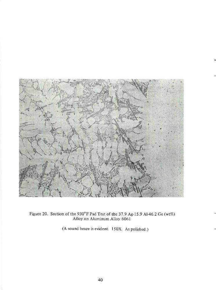
20 Section of the 930°F Pad Test of the 37.9 Ag-15.9 Al-46.2 Ge (wt%) Alloy on Aluminum Alloy 6061 40
21 Section of the 1110°F Pad Test of the 34.1 Ag-14.3 Al-41.6 Ge-10 Y (wt%) Alloy on Aluminum Alloy 6061 41
THE DEVELOPMENT OF FILLER METAL ALLOYS FOR VACUUM BRAZING-GAS QUENCHING OF ALUMINUM ALLOYS
W. J. Werner and G. M. Slaughter Metals and Ceramics Division
Oak Ridge National Laboratory* Oak Ridge, Tennessee 37830
and
F. B. Gurtner Edgewood Arsenal
Edgewood, Maryland 21010
I. INTRODUCTION.
The main objective of this investigation was to develop new brazing filler metals for aluminum alloys, especially of the type that would function in a vacuum and have potential corrosion capability for the mission at Edgewood Arsenal. Previous corrosion studies conducted by Edgewood Arsenal showed that some elements alloyed alone with aluminum were subject to corrosion at a rapid rate.
Three flow temperatures were picked as the most advantageous range for the Army's final use: 950°, 1000°, and 1050°F. The temperature range would provide brazing capability for the high strength aluminum alloys.
II. LITERATURE SURVEY.
The investigation was begun with a survey of the literature. Unfortunately, there is very little published work on fluxless-vacuum and/or inert gas brazing of aluminum. Most of the fluxless brazing work which has been reported was done with the commercial brazing alloy No. 718 (88 wt% Al, 12 wt% Si), using aluminum alloys 2002, 3003, 6061, and 2219 base metals. Also, much of the "fluxless" brazing research was actually performed using a small amount of flux. M. M. Schwartz,1 et al showed the feasibility of vacuum fluxless brazing production quantities of aluminum alloy 6061 containers of helium leaktight quality by closely controlling process parameters using a commercial brazing filler metal. Brazing alloy No. 718 (nominally 88 wt% Al, 12 wt% Si) was used. This alloy is widely used commercially for both dip and furnace brazing and is available in wire and foil forms. Prime importance was placed on metal preparation and cleanliness, which was not surprising. As might be expected, the success of the endeavor was largely due to the use of laboratory cleanliness levels under production conditions. The maximum allowable lag between cleaning and brazing was 12 hr.
Only one other report of equivalent content was found. C. S. Beuyukian2 developed techniques for vacuum or inert gas fluxless brazing of aluminum cold plates for use in Apollo
* Operated by the U. S. Atomic Energy Commission under contract with the Union Carbide Corporation.
1 Schwartz, M. M., Gurtner, F. B., and Shutt, Jr., P. K. Vacuum (or Fluxless) Brazing-Gas Quenching of 6061 Aluminum Alloy. Welding J. (N. Y.) 46(5), 423^31 (May 1967).
2 Beuyukian, C. S. Fluxless Brazing of Apollo Cold Plates - Development and Production. Welding J. (N. Y.) 47(9), 710-719 (September 1968).
Command Modules. In this work brazing filler metal No. 718 and No. 23 brazing sheet were evaluated. As previously stated, alloy No. 718 is nominally 88 wt% Al, 12 wt% Si; No. 23 brazing sheet is comprised of 6951 base alloy clad on one side with 4045 brazing filler metal - nominally 90 wt% Al, 10 wt% Si. Base metals 6061 and 5052 were considered for the main body of the assembly.
In general, better results were obtained using vacuum. The techniques developed are unique in that stringent flatness requirements placed on the assembly by design required that brazing operations be performed in heated platen presses at moderate pressures. The use of pressure during brazing undoubtedly influenced oxide penetration and/or displacement during the brazing operation, thus attaining wetting and flow. Production brazing was carried out in the temperature range 1055° to 1095° F using brazing times of at least 10 min.
Under these conditions, aluminum alloy 6061 was preferred over 5052 because alloy 5052 exhibited a greater susceptibility to intergranular penetration by silicon. Use of alloy 5052 would, therefore, have required more rigid time-temperature control during the brazing cycle. In addition, silicon diffusion resulted in embrittlement of 5052.
No. 23 brazing sheet was chosen for production over the combination of brazing alloy No. 718-6061 for both metallurgical and process advantages. As a single entity it was immediately more desirable from cleaning, assembly, and material handling standpoints. Metallurgically, the 4045 brazing filler metal with its lower silicon content, allowed greater latitude in processing parameters than did alloy No. 718.
Finally, the workers at Aeronca, Inc., a major manufacturer of aerospace structures, completed a study on inert gas brazing of aluminum in early 1967. Their work was concerned with development of high-strength brazed aluminum honeycomb structures which would withstand a range of cryogenic (-423°F) through elevated (600°F) temperatures. The base metals involved in the study were X7005, X7106, and 7039, all of which began to melt within the range 1080° to 1 120°F. As a result, a 1050°F maximum flow temperature for the brazing filler metal was needed.
Three commercial brazing alloys were evaluated in combination with the aforementioned base metals — Nos. 716, 718, and 719. No. 716 contains nominally 86 wt% Al, 10% Si, and 4% Cu; 718 contains nominally 88% Al, 12% Si; and 719 contains nominally 76% Al, 10% Si, 10% Zn, and 4% Cu. It was found that the aluminum-silicon brazing alloys performed best as claddings.
The researchers developed several new brazing alloys during the course of their investigation. Two, in particular, showed promise. Both alloys had a base composition of 68% Al, 7% Si, 15% Ge; their compositions were modified with 10% Zn, and 10% Ag, respectively. Both alloys brazed at 1020°F. These new alloys looked especially good in combination with X7106. Alloy 719 remained the number one choice for brazing X7005.
The base metals of interest in the present study were 6061, 2219, 7075, and 2024. Joining of alloys 6061 and 2219 is accomplished industrially by dip or furnace brazing techniques both of which employ liberal amounts of flux. In addition, alloy 6061 has also been brazed without flux using vacuum and/or inert atmospheres.1,2 As a result, good cleaning and handling procedures
3 Fluxless Brazing Makes Headway. Iron Age 200, 67-68 (August 10, 1967).
are not problems with these two alloys. In fact, cleaning procedures are available in the Metals and Ceramics Division of Oak Ridge National Laboratory for both of these alloys since they are routinely hot roll-bonded into dispersion-type fuel plates using standard picture-frame techniques. Since aluminum alloy 6061 is used as a structural material in a number of applications, we concentrated on the brazing of it in this study. We also made a cursory evaluation of the brazability of aluminum alloys 2219, 2024, and 7075. Although there are basic compositional differences between 2219 and 6061 [6061 nominally contains 0.25 Cu, 0.6 Si, 1.0 Mg, and 0.25 Cr(wt%)and 2219 nominally contains 6.3 Cu and 0.3 Mn (wt%)], our research indicated that they would braze similarly. The same cleaning procedures could be used and the melting ranges for the two base metals were about the same. Pad tests for wettability showed that experimental brazing filler metals which wet 6061 would also wet 2219.
Aluminum alloys 2024 and 7075, on the other hand, are not considered commercially brazable using established commercial techniques and commercial brazing filler alloys. Both alloys contain relatively high amounts of magnesium (1.5 and 2.5 wt%, respectively). Normally, alloys with magnesium contents greater than 2.0% are considered difficult to braze industrially; and alloys with magnesium contents greater than 2.5% are considered unbrazable. This is due to the fact that state-of-the-art fluxes do not remove the tenacious oxides formed on these alloys. Perhaps even more important, their melting ranges are considerably lower than those of 6061 and 2219 (table I). We immediately found that these alloys are not amenable to the chemical cleaning procedure found adequate for 6061 and 2219. Our metallographic group found that these alloys could be electropolished, even though they are not readily cleaned by chemical means. Both alloys responded satisfactorily to a low-temperature perchloric acid electropolishing treatment.
Our initial studies consisted of the determination of the upper brazing temperature limit for these base metals. Using our normal 6061 brazing cycle of about 30 min (total time in brazing furnace), we found that 7075 could not be exposed to temperatures above 1000°F, and 2024 could not be exposed to temperatures above 1080°F. In the temperature range 1020°F to 1150°F (for our particular thermal cycle), localized incipient melting occurred in alloy 7075. At 1180°F, the alloy was completely molten. Alloy 2024 sagged in the temperature range 1 100°F to 1 150°F and was also completely molten at 1180°F. These experiments indicate that the maximum brazing temperatures of aluminum alloys 7075 and 2024 are 1000 and 1080°F, respectively. The solidus temperatures of these alloys are reported as 900°F and 930°F.4 It is envisioned that one would ideally prefer to braze these alloys below the solidus where alloying and/or reaction rates would be considerably slower.
III. EQUIPMENT AND EXPERIMENTAL PROCEDURES.
The vacuum-furnace apparatus for flow temperature and wettability determinations is shown in figure 1. The system is capable of maintaining a vacuum of 1 X 10 torr at brazing temperature. The picture shows the furnace rolled back off the muffle. In a typical brazing cycle the specimen is placed into the cold muffle. After pump-down, the heated furnace is rolled onto the muffle and the work very rapidly comes to temperature. After holding for the proper brazing time the furnace is rolled off the muffle. Simultaneously with the former operation, helium can be admitted to facilitate rapid cooling or quenching of the test assembly. Diffusion effects can probably be limited by both of these operations.
4 Metals Handbook, 8th Edition. Vol. 1.
M C
«-> -J
^ •a c c 0 03
n i>
E T3 CO
-1 c 0
CO () c 0 1) .-^ X) CO C o a D E CO
0 0 u __ < m C <4H
(5
E CO o 1)
2 &0 c cd
a: w m -c - p-
u 4*1 O o o O o o o O Ctf OH O o OS ON 00 00 00 oo a -5 oo PH •
r-i
prox
m
elt
ran ° 6 1 o 6 6 6 d i
in in oo oo ,—. — ON ON OO CO o o o o 00 oo ON ON
O, t—i «—1 — •—1
<
o 1—1
H m 1
1 c\ q ^3
q o n d
1 I 1
i_^ c N m
CN 1 O
NC I
in NC
in
in CN 1
m 1/1 co co 4 o
i' oo o o
q r; 1 1 co 1
<N ON 00
00 ^ ri ^ c o
S oo q q 1 i
in i
CN in — ri ri --^ i—<
'53 o £ E o c
2
o -t Os
u m r o o O d •—< I CN ro m co NO
d d d
o •* 00 q ON
3 u m 1 00 co
ri • CN VO
4 1
00 "ct in vd "—' 1 ' ro Tt
u O o o C"; 1 tn 1 ir\ 1 in 1 d
oo C/5 6 o o O
^ NO <N 1 5F 1 in 1
^ 00 c • — E o Z
r—- ^-^ ^^
c 'So c 53 s 30
S "3 00 3 "o3
e
All
oy
gnat
io 1 1
o 2 3 1 E
0 £ a o 2 1—' ^_ <N •—• '— — "•^
t« ,—1 ^-i ON ON IT) m Tf •^f a> NO NC i—i i—i t"> r~ CN r-i •o o o CN CN o O O o
VO NO CN C4 r- r~ c) cs
in Ci
o d '—' o E 00
3 C o O o E
•a a N c
o IT) u
.a 9
N
m O o o o E E 3 3
•o •n 03 03 C c 03 03
> >
10
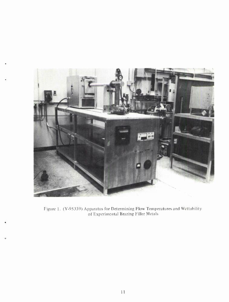
Figure 1. (Y-95339) Apparatus for Determining Flow Temperatures and Wettability of Experimental Brazing Filler Metals
11
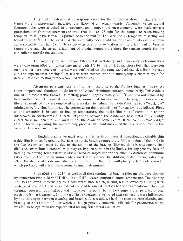
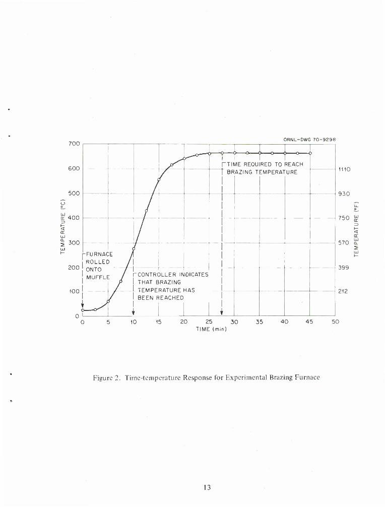
A typical time-temperature response curve for the furnace is shown in figure 2: the temperature measurements indicated are those of an actual sample. Chromel-P versus alumel thermocouples were attached to a specimen, and temperature measurements were made using a potentiometer. Our measurements showed that it takes 25 min for the sample to reach brazing temperature after the furnace is pushed onto the muffle. The variation in temperature setting was found to be ±5°F. It is believed that the inherently poor heat-transfer characteristics of a vacuum are responsible for the 15-min delay between controller indication of the attainment of brazing temperature and the actual attainment of brazing temperature since the sensing couple for the controller is outside the vacuum.
The majority of our brazing filler metal wettability and flowability determinations were done using 6061 aluminum base metal pads 1/2 by 1/2 by 1/16 in. Those tests that were run on the other base metals of interest were performed on this same standard pad size. Both the pads and the experimental brazing filler metals were cleaned prior to undergoing a thermal cycle for determination of melting temperature and wettability.
Attention to cleanliness is of prime importance to the fluxless brazing process. At room temperature, aluminum oxide forms on "clean" aluminum surfaces immediately. This oxide is one of the most stable known. Its melting point is approximately 3700°F and it is not reduced by heat and/or normal chemical cleaners. In commercial furnace and dip brazing processes where liberal amounts of flux are employed care is taken to reduce the oxide thickness to a "workable" minimum before flux is applied. The consensus on the mechanism of flux action is as follows: First, as the assembly is brought to brazing temperature, the oxide film microfissures due to the differences in coefficients of thermal expansion between the oxide and base metal. Flux readily enters these microfissures and undermines the oxide to some extent. If the oxide is "workably" thin, it breaks up during the undermining process. This continues until the flux is consumed or the metal surface is cleared of oxide.
In fluxless brazing we must assume that, as in commercial operation, a workably thin oxide film is microfissured during heat-up to the brazing temperature. Undermining of the oxide in the fluxless process must be due to the action of the brazing filler metal. It is noteworthy that diffusion (over short distances) may play an important role in the fluxless brazing process. Rate of heating to brazing temperature is also a factor of major importance since oxidation of aluminum takes place in the best vacuums and/or inert atmospheres. In addition, faster heating rates may affect the degree of oxide microfissuring. In any event there is a multiplicity of factors to consider which probably will affect the vacuum brazing of aluminum.
Both 6061 and 2219, as well as all the experimental brazing filler metals, were cleaned by immersion into a 20 vol% HN03-2 vol% HF-water solution at room temperature. The cleaning step was followed immediately by a cold water rinse which, in turn, was followed by flushing with acetone. Alloys 2024 and 7075 did not respond to our satisfaction to the aforementioned chemical cleaning process. Both alloys did, however, respond to a low-temperature perchloric acid electropolishing treatment. In our very first experiments we noted that test results were influenced by the time span between cleaning and brazing. As a result, we held the time between cleaning and brazing to a maximum of 1 hr which, although possibly somewhat difficult for production work, was felt to be optimum for experimental brazing filler metal evaluation.
12
700
600
500
cr 400
UJ
| 300
200
ORNL-DWG 70-9298
100
yr L__l_ „1_ >
TTIME REQUIRED TO REACH
BR AZING T EMPERA1 URE
-FURNAC ROLLEC
E J ) /
ONTO
MUFFLE / -CONTRC THAT B TFMPF
)LLER IN RAZING
RATURE
DICATES
HAS
? ^/ / 1 BEEN F r 1
1
EACHED
' r 10 15 20 25 30
TIME (min) 35 40 45
1110
930
750
570
399
212
a r>
< or UJ a
50
Figure 2. Time-temperature Response for Experimental Brazing Furnace
13
IV. FORMULATIONS OF EXPERIMENTAL BRAZING FILLER METAL COMPOSITIONS.
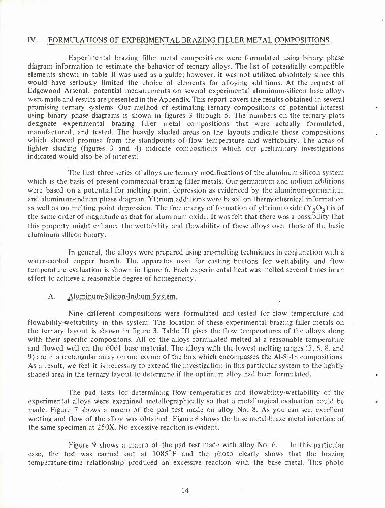
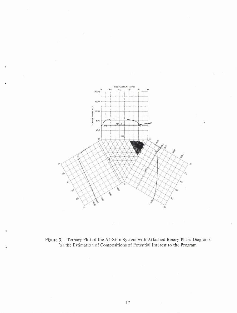
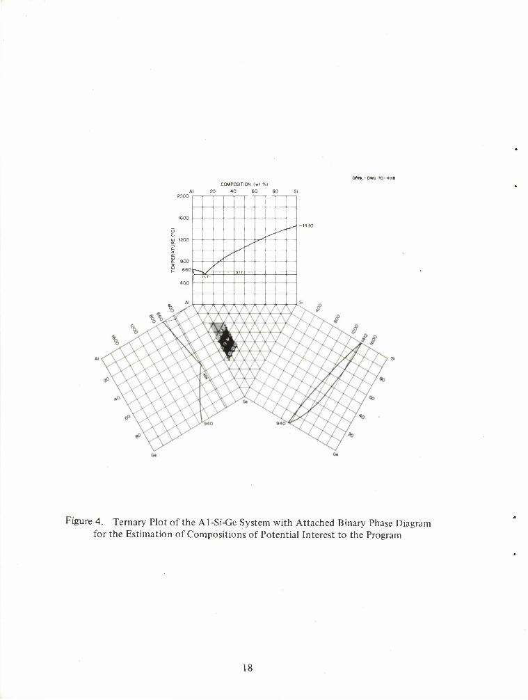
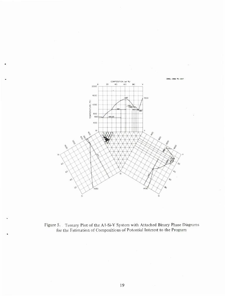
Experimental brazing filler metal compositions were formulated using binary phase diagram information to estimate the behavior of ternary alloys. The list of potentially compatible elements shown in table II was used as a guide; however, it was not utilized absolutely since this would have seriously limited the choice of elements for alloying additions. At the request of Edgewood Arsenal, potential measurements on several experimental aluminum-silicon base alloys were made and results are presented in the Appendix. This report covers the results obtained in several promising ternary systems. Our method of estimating ternary compositions of potential interest using binary phase diagrams is shown in figures 3 through 5. The numbers on the ternary plots designate experimental brazing filler metal compositions that were actually formulated, manufactured, and tested. The heavily shaded areas on the layouts indicate those compositions which showed promise from the standpoints of flow temperature and wettability. The areas of lighter shading (figures 3 and 4) indicate compositions which our preliminary investigations indicated would also be of interest.
The first three series of alloys are ternary modifications of the aluminum-silicon system which is the basis of present commercial brazing filler metals. Our germanium and indium additions were based on a potential for melting point depression as evidenced by the aluminum-germanium and aluminum-indium phase diagram. Yttrium additions were based on thermochemical information as well as on melting point depression. The free energy of formation of yttrium oxide (Y203) is of the same order of magnitude as that for aluminum oxide. It was felt that there was a possibility that this property might enhance the wettability and flowability of these alloys over those of the basic aluminum-silicon binary.
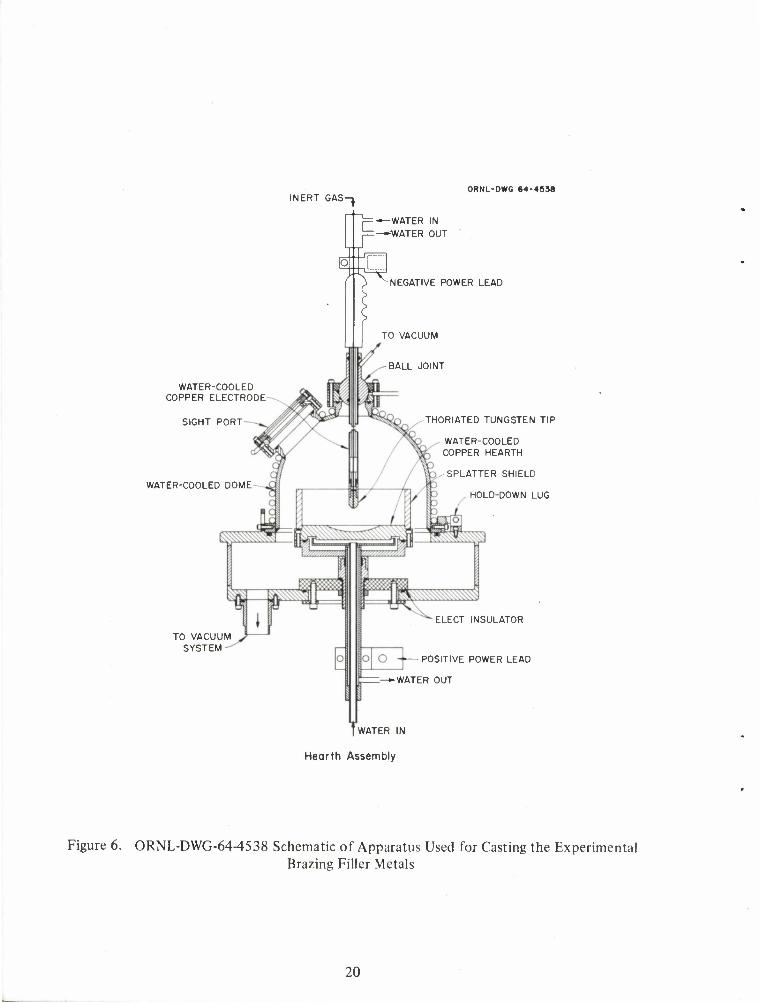
In general, the alloys were prepared using arc-melting techniques in conjunction with a water-cooled copper hearth. The apparatus used for casting buttons for wettability and flow temperature evaluation is shown in figure 6. Each experimental heat was melted several times in an effort to achieve a reasonable degree of homegeneity.
A. Aluminum-Silicon-Indium System.
Nine different compositions were formulated and tested for flow temperature and flowability-wettability in this system. The location of these experimental brazing filler metals on the ternary layout is shown in figure 3. Table III gives the flow temperatures of the alloys along with their specific compositons. All of the alloys formulated melted at a reasonable temperature and flowed well on the 6061 base material. The alloys with the lowest melting ranges (5, 6, 8, and 9) are in a rectangular array on one corner of the box which encompasses the Al-Si-In compositions. As a result, we feel it is necessary to extend the investigation in this particular system to the lightly shaded area in the ternary layout to determine if the optimum alloy had been formulated.
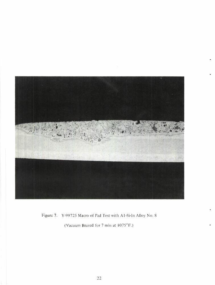
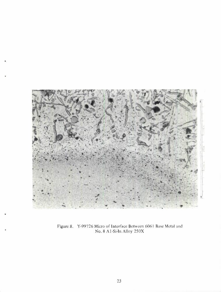
The pad tests for determining flow temperatures and flowability-wettability of the experimental alloys were examined metallographically so that a metallurgical evaluation could be made. Figure 7 shows a macro of the pad test made on alloy No. 8. As you can see, excellent wetting and flow of the alloy was obtained. Figure 8 shows the base metal-braze metal interface of the same specimen at 250X. No excessive reaction is evident.
Figure 9 shows a macro of the pad test made with alloy No. 6. In this particular case, the test was carried out at 1085°F and the photo clearly shows that the brazing temperature-time relationship produced an excessive reaction with the base metal. This photo
14
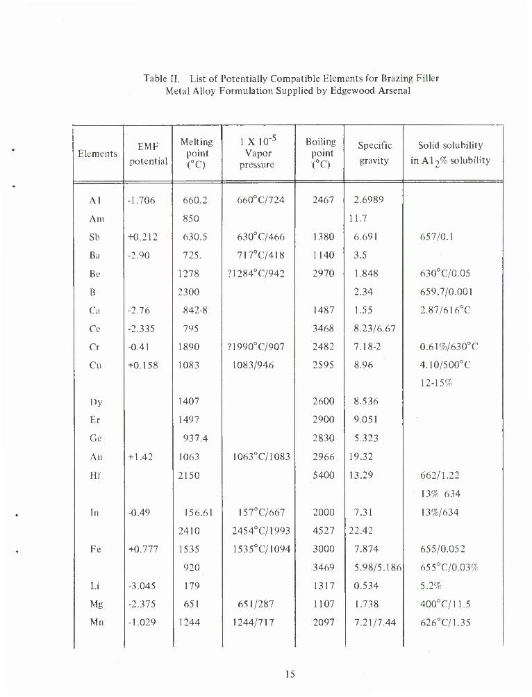
Table II. List of Potentially Compatible Elements for Brazing Filler Metal Alloy Formulation Supplied by Edgewood Arsenal
Elements EMF
potential
Melting point (°C)
1 X 10"5
Vapor pressure
Boiling point (°C)
Specific
gravity
Solid solubility
in Al2% solubility
Al -1.706 660.2 660°C/724 2467 2.6989
Am 850 11.7
Sb +0.212 630.5 630°C/466 1380 6.691 657/0.1
Ba -2.90 725. 717°C/418 1140 3.5
Be 1278 ?1284°C/942 2970 1.848 630°C/0.05
B 2300 2.34 659.7/0.001
Ca -2.76 842-8 1487 1.55 2.87/616°C
Ce -2.335 795 3468 8.23/6.67
Cr -0.41 1890 ?1990°C/907 2482 7.18-2 0.61%/630°C
Cu +0.158 1083 1083/946 2595 8.96 4.10/500°C
12-15%
Dy 1407 2600 8.536
Er 1497 2900 9.051
Ge 937.4 2830 5.323
Au + 1.42 1063 1063°C/1083 2966 19.32
Hf 2150 5400 13.29 662/1.22
13% 634
In -0.49 156.61 157°C/667 2000 7.31 13%/634
2410 2454°C/1993 4527 22.42
Fe +0.777 1535 1535°C/1094 3000 7.874 655/0.052
920 3469 5.98/5.186 655°C/0.03%
Li -3.045 179 1317 0.534 5.2%
Mg -2.375 651 651/287 1107 1.738 400°C/11.5
Mn -1.029 1244 1244/717 2097 7.21/7.44 626°C/1.35
15
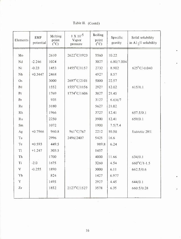
Table II. (Contd)
Elements EMF
potential
Melting point (°C)
1 X 10"5
Vapor pressure
Boiling
point (°C)
Specific
gravity
Solid solubility
in Al2% solubility
Mo 2610 2622°C/1923 5560 10.22
Nd -2.246 1024 3027 6.80/7.004
Ni -0.23 1453 1455°C/1157 2732 8.902 625°C/-0.040
Nb +0.344? 2468 4927 8.57
Os 3000 2697°C/2101 5000 22.57
Pd 1552 1555°C/1156 2927 12.02 615/0.1
Pt 1769 1774°C/1606 3827 21.45
Pr 935 3127 6.6/6/7
Re 3180 5627 21.02
Rh 1966 3727 12.41 657.5/0.1
Ru 2250 3900 12.41 659/0.1
Sm 1072 1900 7.5/7.4
Ag +0.7966 960.8 961°C/767 2212 10.50 Eutectic 28%
Ta 2996 2496/2407 5425 16.6
Te +0.593 449.5 989.8 6.24
Tl + 1.247 303.5 1457
Th 1700 4000 11.66 634/0.1
Ti -2.0 1675 3260 4.54 660° C/1-1.5
V -0.255 1890 3000 6.11 662.5/0.6
Yb 824 1427 6.977
Y 1495 2927 4.45 644/0.1
Zr 1852 2127°C/1527 3578 6.35 660.5/0.28
16
COMPOSITION (wr%) In 80 60 40 20 Al
__ .-- — _ 6)7 tj
^»T 2 n
~<ss
Figure 3. Ternary Plot of the Al-Si-In System with Attached Binary Phase Diagrams for the Estimation of Compositions of Potential Interest to the Program
17
ORNL-DWG 70-4H8 COMPOSITION (wl %l
Al 20 40 60 80
J
t /
r-» / /
f-
Figure 4. Ternary Plot of the A1 -Si-Ge System with Attached Binary Phase Diagram for the Estimation of Compositions of Potential Interest to the Program
18
OHNL-DWG TO-4M7 COMPOSITION («l %)
Al 20 40 60 80
Figure 5. Ternary Plot of the Al-Si-Y System with Attached Binary Phase Diagrams for the Estimation of Compositions of Potential Interest to the Program
19
INERT GAS- ORNL-DWG 64-4938
WATER-COOLED COPPER ELECTRODE
SIGHT PORT
WATER-COOLED DOME
u
n. r -WATER IN
-•WATER OUT
X NEGATIVE POWER LEAD
TO VACUUM
BALL JOINT
TO VACUUM SYSTEM-
THORIATED TUNGSTEN TIP
WATER-COOLED COPPER HEARTH
SPLATTER SHIELD
HOLD-DOWN LUG
ELECT INSULATOR
POSITIVE POWER LEAD
WATER OUT
[WATER IN
Hearth Assembly
Figure 6. ORNL-DWG-64-4538 Schematic of Apparatus Used for Casting the Experimental Brazing Filler Metals
20
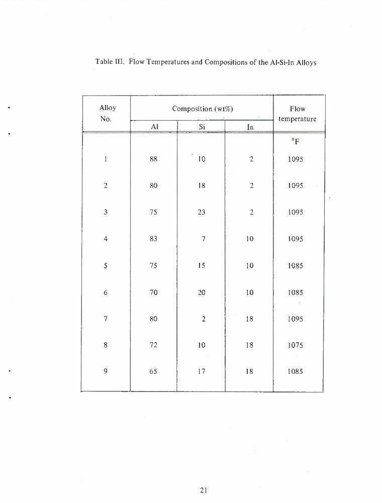
Table III. Flow Temperatures and Compositions of the Al-Si-In Alloys
Alloy Composition (wt%) Flow
No. temperature Al Si In
°F
1 88 10 2 1095
2 80 18 2 1095
3 75 23 2 1095
4 83 7 10 1095
5 75 15 10 1085
6 70 20 10 1085
7 80 2 18 1095
8 72 10 18 1075
9 65 17 18 1085
21
K- "M»
•
Figure 7. Y-99725 Macro of Pad Test with Al -Si-In Alloy No.
(Vacuum Brazed for 7 min at 1075°F.)
22
J
Figure 8. Y-99726 Micro of Interface Between 6061 Base Metal and No. 8 Al-Si-InAlloy 250X
23
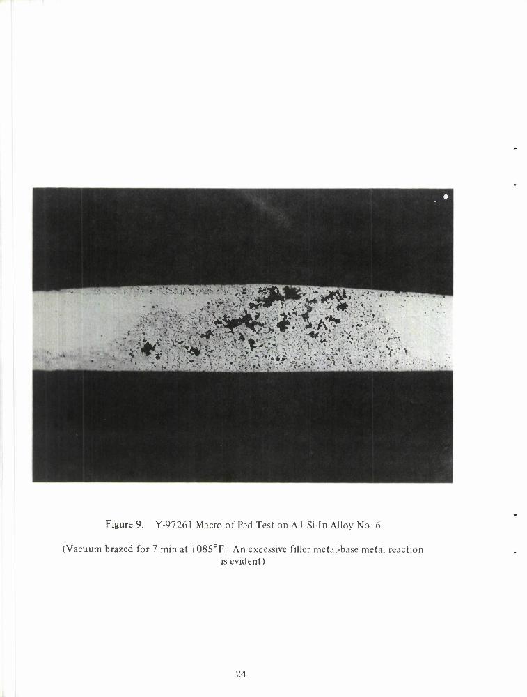
Figure 9. Y-97261 Macro of Pad Test on Al-Si-In Alloy No. 6
(Vacuum brazed for 7 min at 1085°F. An excessive filler metal-base metal reaction is evident)
24
clearly points out that aluminum brazing results are highly sensitive to small changes in brazing time and temperature due to the fact that the melting points of the brazing filler metals are quite close to the melting points of the base metals. The same alloy was subsequently used to braze the T-joint shown in figure 10 using a slightly shorter brazing cycle with obviously much improved results. Our experience indicates that even further improvement is possible.
Initial attempts to fabricate alloys in this system by hot-swaging have met with limited success. It may be necessary to break down the cast structure by extrusion before hot-swaging to wire.
B. Aluminum-Silicon-Germanium System.
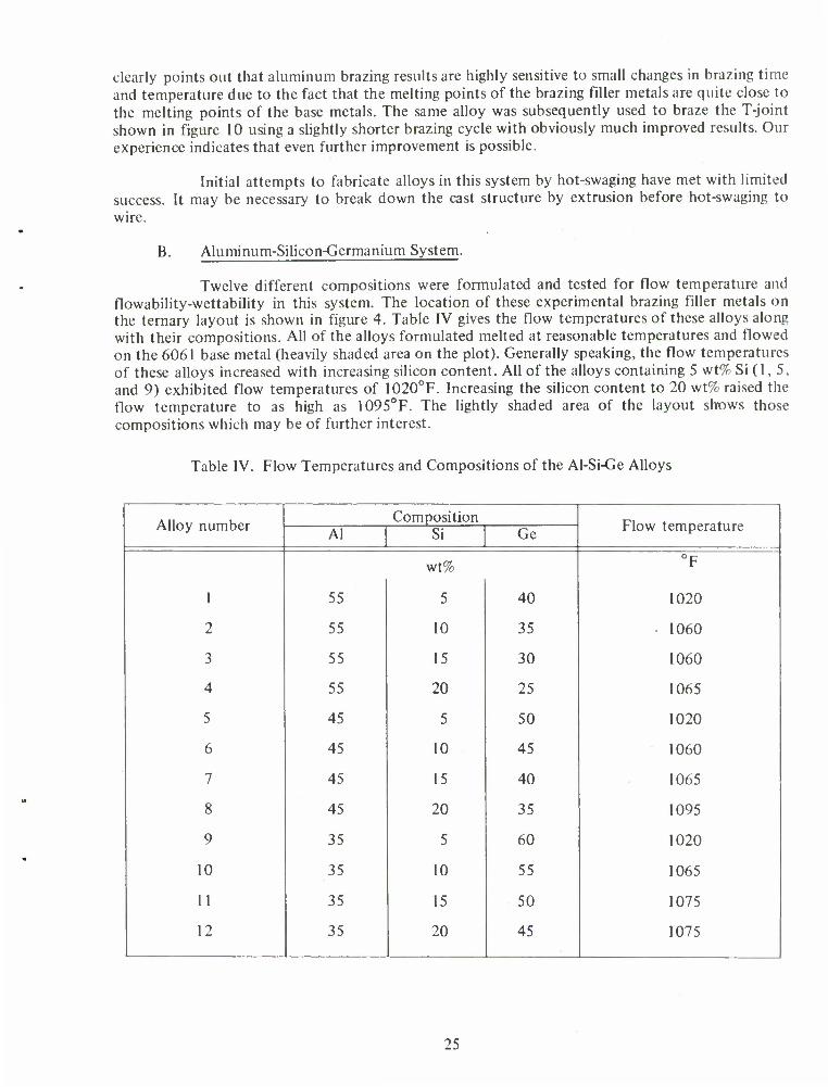
Twelve different compositions were formulated and tested for flow temperature and flowability-wettability in this system. The location of these experimental brazing filler metals on the ternary layout is shown in figure 4. Table IV gives the flow temperatures of these alloys along with their compositions. All of the alloys formulated melted at reasonable temperatures and flowed on the 6061 base metal (heavily shaded area on the plot). Generally speaking, the flow temperatures of these alloys increased with increasing silicon content. All of the alloys containing 5 wt% Si (1, 5, and 9) exhibited flow temperatures of 1020°F. Increasing the silicon content to 20 wt% raised the flow temperature to as high as 1095°F. The lightly shaded area of the layout shows those compositions which may be of further interest.
Table IV. Flow Temperatures and Compositions of the Al-Si-Ge Alloys
Alloy number Composition
Flow temperature Al Si Ge
wt% °F
1 55 5 40 1020
2 55 10 35 1060
3 55 15 30 1060
4 55 20 25 1065
5 45 5 50 1020
6 45 10 45 1060
7 45 15 40 1065
8 45 20 35 1095
9 35 5 60 1020
10 35 10 55 1065
11 35 15 50 1075
12 35 20 45 1075
25
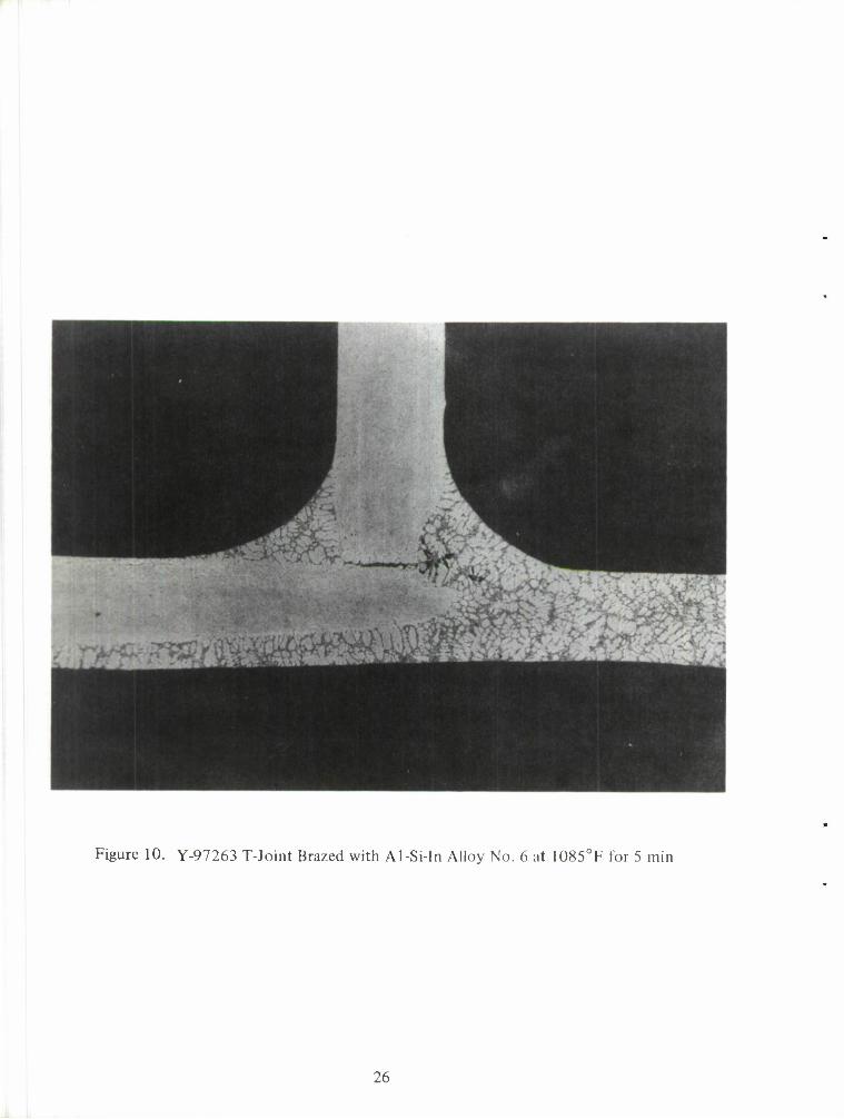
Figure 10. Y-97263 T-Joint Brazed with Al-Si-In Alloy No. 6 at 1085°F for 5 min
26
Figure 11 shows a series of typical pad tests made at different temperatures (in vacuum) with the filler metal No. 9. Using successively lower test temperatures, we established that the flow temperature of this alloy was 1020°F. Note the excellent flowability and wettability of this experimental composition at all temperatures tested. We subsequently used this same alloy to make the T-joint shown in figure 12, in which the brazing filler metal is preplaced at one end of the joint and flow proceeds along the capillary. The base metal for the T-joint was 6061, and the braze was performed by holding for 2-1/2 min at 1020°F. Good filleting is evident.
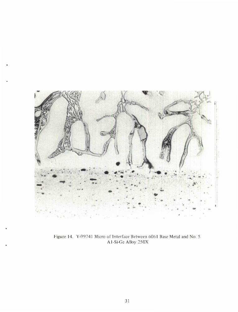
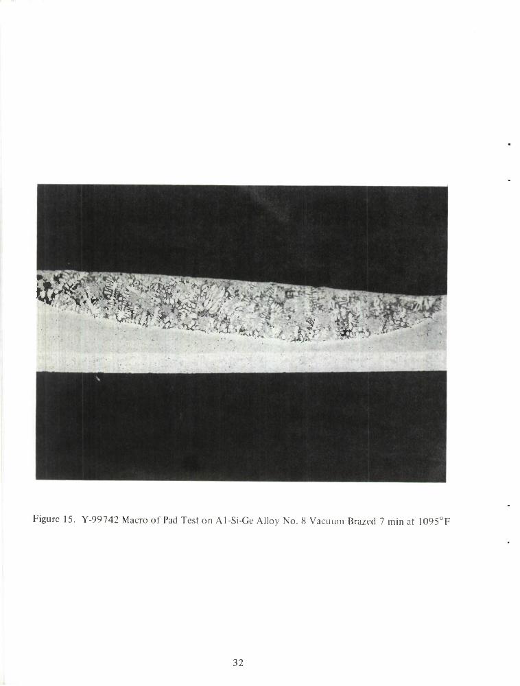
Figure 13 shows a macro of the 1020°F pad test performed on alloy No. 5. The 1020°F brazing temperature, 7-min brazing time combination appears to be slightly excessive for this alloy since reaction completely through the pad had taken place. Nevertheless, the wetting and flow exhibited is quite good. It should be noted that this brazing temperature is lower than that used for commercial state-of-the-art brazing filler metals and as such is a significant advancement in aluminum brazing technology. Figure 14 shows a high magnification view of the interface between base metal and braze metal for this particular pad test. Both photos suggest that this composition is very near the Al-Si-Ge eutectic composition. Figures 15 and 16 show the pad test results for one of the higher melting Al-Si-Ge alloys, No. 8. This was the highest melting of this series of alloys. This filler metal also has excellent flow and wetting characteristics and is typical of the higher melting alloys. The degree of reaction with the base metal is satisfactory.
All of the Al-Si-Ge alloys were quite brittle and were not amenable to fabrication into wire or sheet by conventional techniques.
C. Aluminum-Silicon-Yttrium System.
Twenty different compositions were formulated and tested for flow temperature and flowabiltiy-wettability in this system. The location of these experimental brazing filler metals on the ternary layout is shown in figure 5. The lightly shaded area shows the location of the most promising compositions. Table V gives the flow temperatures of the alloys that melted below the melting point of the 6061 base metal and the compositions of all the alloys tested.
The higher flow temperatures of these alloys rather limits their use per se as ternary alloys. However, one must remember that additions of minor quantities of elements such as Cu, Sn, Zn, etc., could result in considerable flow point reduction.
Of the seven experimental compositions in this ternary system which did melt below 1150°F, excellent wetting and flow on 6061 base metal was obtained. Alloy No. 18 (70 Al - 25 Si - 5 Y wt%) exhibited the lowest flow temperature. However, as was the case for some compositions in the other series investigated, base metal-filler metal interaction occurred rapidly and excessive penetration was a problem. Thus, careful control of the time-temperature thermal cycle (or further alloying with additional melting point depressants) is necessary.
The alloys in the Al-Si-Y system were much more fabricable than any of the other experimental brazing filler metals investigated. They were readily reduced to 1/16-in. wire as shown in figure 1 7.
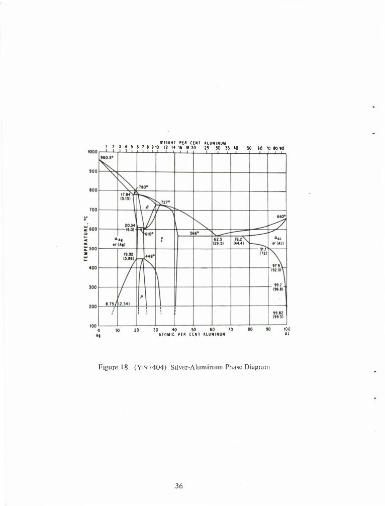
D. Silver-Bearing Alloys.
A series of ternary and quaternary experimental brazing filler metals based on the silver-aluminum system (figure 18) were formulated, melted, and tested on 6061 base metal for
27
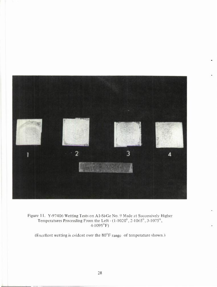
Figure 11. Y-97406 Wetting Tests on Al-Si-Ge No. 9 Made at Successively Higher Temperatures Proceeding From the Left -(1-1020°, 2-1065°, 3-1075°,
4-1095°F)
(Excellent wetting is evident over the 80°F range of temperature shown.)
28
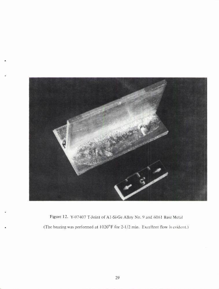
Figure 12. Y-97407 T-Joint of Al-Si-Ge Alloy No. 9 and 6061 Base Metal
(The brazing was performed at 1020°F for 2-1/2 min. Excellent flow is evident.)
29
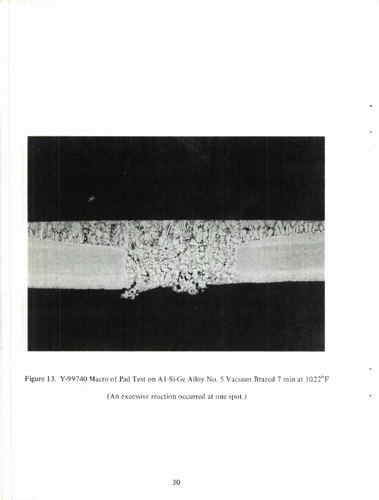
Figure 13. Y-99740 Macro of Pad Test on Al-Si-Ge Alloy No. 5 Vacuum Brazed 7 min at 1022°F
(An excessive reaction occurred at one spot.)
30
-. * -
V* •
Figure 14. Y-99741 Micro of Interface Between 6061 Base Metal and No. 5 Al-Si-Ge Alloy 25OX
31
"fC-.v
'' '^ft jw.'.m*-?'
Figure 15. Y-99742 Macro of Pad Test on Al-Si-Ge Alloy No. 8 Vacuum Brazed 7 min at 1095°F
32
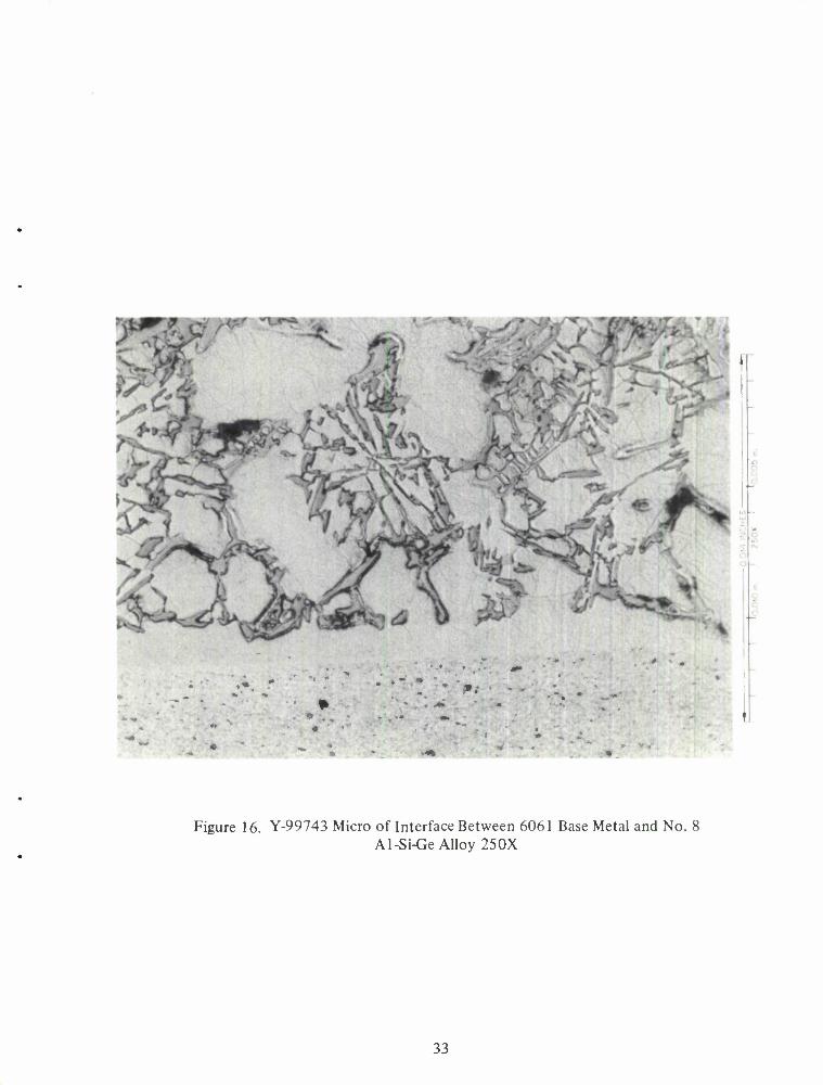
Figure 16. Y-99743 Micro of Interface Between 6061 Base Metal and No. 8 Al-Si-Ge Alloy 250X
33
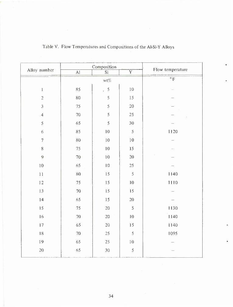
Table V. Flow Temperatures and Compositions of the Al-Si-Y Alloys
Alloy number Composition
Flow temperature Al Si Y
wt% °F
1 85 . 5 10 -
2 80 5 15 -
3 75 5 20 -
4 70 5 25 -
5 65 5 30 -
6 85 10 5 1120
7 80 10 10 -
8 75 10 15 -
9 70 10 20 -
10 65 10 25 -
11 80 15 5 1140
12 75 15 10 1110
13 70 15 15 -
14 65 15 20 -
15 75 20 5 1130
16 70 20 10 1140
17 65 20 15 1140
18 70 25 5 1095
19 65 25 10 -
20 65 30 5 -
34
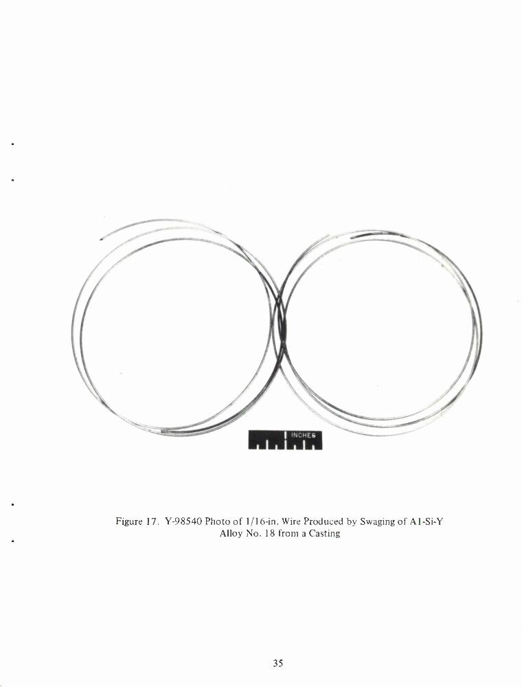
Figure 17. Y-98540 Photo of 1/16-in. Wire Produced by Swaging of Al-Si-Y Alloy No. 18 from a Casting
35
WEIGHT PER CENT ALUMINUM 1 2 3 4 5 6 7 S J H) 12 14 16 18 20 2S JO 35 40 M (0 '0 M tO
J—| | |
0 *9
10 20 30 40 50 60 70 ATOMIC PER CENT ALUMINUM
100 Al
Figure 18. (Y-97404) Silver-Aluminum Phase Diagram
36
wetting and flow properties. The compositions and flow temperatures of the filler metals are shown in table VI. We were most pleased to find that the Ag-Al-Ge ternary alloy (alloy No. 5) had a flow temperature as low as 930°F. Once again this is a significant contribution since alloys melting at this temperature are necessary for the lower melting, high-strength aluminum alloys (i.e., 7075, 2024). Several other compositions in this table also flowed well; however, the brazing temperatures were somewhat higher.
Table VI. Composition and Flow Temperatures of Silver-Bearing Experimental Brazing Alloys
Alloy No.
O imposition (wt%) Flow temperature
Ag Al In Ge Y
°F
1 61.5 25.7 12.8 - - 1075
2 58.3 24.1 12.6 - 5.0 1110
3 55.4 23.1 11.5 - 10.0 Above 1150
4 52.3 21.8 10.9 - 15.0 Above 1150
5 37.9 15.9 - 46.2 - 930
6 36.0 15.1 - 43.9 5.0 1000
7 34.1 14.3 - 41.6 10.0 Above 1110
8 32.2 13.5 - 39.3 15.0 1150
37
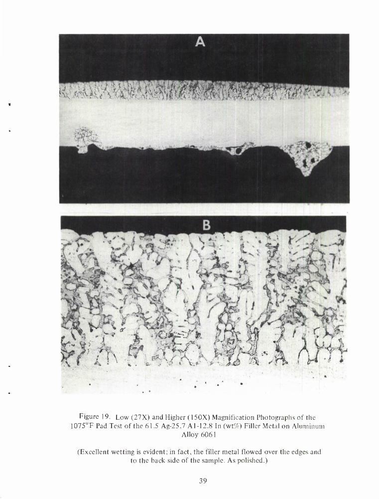
Pad test specimens were sectioned and metallographically examined. From the standpoint of braze metal-base metal interaction and flow, alloy No. 1 (61.5 Ag-25.7 Al-12.8 In, wt%) looks very attractive. Figure 19 (A) and (B) show the braze made at 1075°F at both low and higher magnifications. Figure 20 shows a section of the pad test made with the low-melting alloy No. 5 (37.9 AG-15.9 Al-46.2 Ge, wt%) at 930°F. Good bonding is evident. It should be noted that 930°F is in the right range for brazing the base metals 7075 and 2024.
An interesting phenomenon is shown in figure 21 in which the brazing filler metal (34.1 Ag-14.3 Al-41.6 Ge-10.0 Y, wt%) did not completely melt, yet appeared to "settle" into the 6061 alloy base metal. It would be expected that severe base-metal erosion would occur if the brazing temperature were to be raised substantially.
E. Magnesium-Bearing Alloys.
Magnesium-bearing experimental brazing alloys could not be melted using conventional arc-melting techniques. We successfully developed techniques for preparing 10-gram buttons of several magnesium-bearing alloys; with this procedure we used a resistance-heated graphite crucible in an inert atmosphere. The alloys formulated (table VII) are binary eutectic compositions. The eutectic temperatures are also shown in the table.
Table VII. Compositions of Magnesium-Bearing Eutectic Alloys and Their Respective Eutectic Temperatures
Alloy
No. Composition (wt%) Eutectic
temperature Mg Ge Ag Al
°F
1 17.7 82.3 -' - 1260
2 96.6 3.4 - - 1170
3 51.5 - 48.5 - 880
4 10.1 - 89.9 - 1400
5 35.5 - - 64.5 840
6 67.7 - - 32.3 820
Pad tests using the lowest melting binary alloys, 3, 5, and 6, were run at 930°F on 6061 pads. Flow of the experimental alloys was obtained in all three cases and the results looked very promising. Further studies are merited using this melting technique and all of the aforementioned binary alloys. It appeared that several attractive ternary and quaternary filler metals could be derived from these systems.
38
. .
Figure 19. Low (27X) and Higher (150X) Magnification Photographs of the 1075°F Pad Test of the 61.5 Ag-25.7 Al-12.8 In (wt%) Filler Metal on Aluminum
Alloy 6061
(Excellent wetting is evident; in fact, the filler metal flowed over the edges and to the back side of the sample. As polished.)
39
v
* • $
v ^#O?(I>J V * / s
Figure 20. Section of the 930°F Pad Test of the 37.9 Ag-15.9 Al-46.2 Ge (wt%) Alloy on Aluminum Alloy 6061
(A sound braze is evident. 150X. As polished.)
40
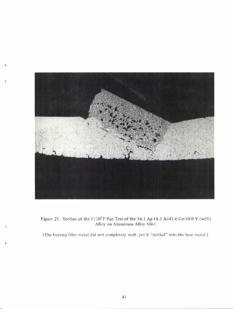
Figure 21. Section of the 1110°F Pad Test of the 34.1 Ag-14.3 Al-41.6 Ge-10.0 Y (wt%) Alloy on Aluminum Alloy 6061
(The brazing filler metal did not completely melt, yet it "settled" into the base metal.)
41
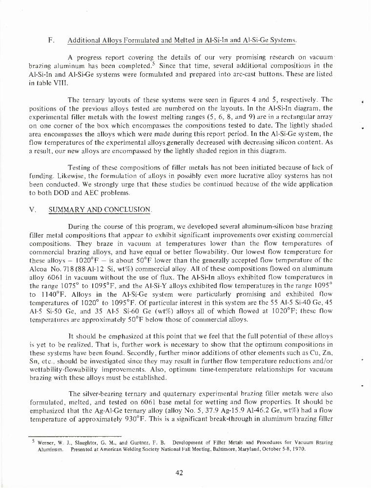
F. Additional Alloys Formulated and Melted in Al-Si-In and Al-Si-Ge Systems.
A progress report covering the details of our very promising research on vacuum brazing aluminum has been completed.5 Since that time, several additional compositions in the Al-Si-In and Al-Si-Ge systems were formulated and prepared into arc-cast buttons. These are listed in table VIII.
The ternary layouts of these systems were seen in figures 4 and 5, respectively. The positions of the previous alloys tested are numbered on the layouts. In the Al-Si-In diagram, the experimental filler metals with the lowest melting ranges (5, 6, 8, and 9) are in a rectangular array on one corner of the box which encompasses the compositions tested to date. The lightly shaded area encompasses the alloys which were made during this report period. In the Al-Si-Ge system, the flow temperatures of the experimental alloys generally decreased with decreasing silicon content. As a result, our new alloys are encompassed by the lightly shaded region in this diagram.
Testing of these compositions of filler metals has not been initiated because of lack of funding. Likewise, the formulation of alloys in possibly even more lucrative alloy systems has not been conducted. We strongly urge that these studies be continued because of the wide application to both DOD and AEC problems.
V. SUMMARY AND CONCLUSION.
During the course of this program, we developed several aluminum-silicon base brazing filler metal compositions that appear to exhibit significant improvements over existing commercial compositions. They braze in vacuum at temperatures lower than the flow temperatures of commercial brazing alloys, and have equal or better flowability. Our lowest flow temperature for these alloys - 1020°F - is about 50°F lower than the generally accepted flow temperature of the Alcoa No. 718 (88 Al-12 Si, wt%) commercial alloy. All of these compositions flowed on aluminum alloy 6061 in vacuum without the use of flux. The Al-Si-In alloys exhibited flow temperatures in the range 1075° to 1095°F, and the Al-Si-Y alloys exhibited flow temperatures in the range 1095° to 1140°F. Alloys in the Al-Si-Ge system were particularly promising and exhibited flow temperatures of 1020° to 1095°F. Of particular interest in this system are the 55 Al-5 Si-40 Ge, 45 Al-5 Si-50 Ge, and 35 Al-5 Si-60 Ge (wt%) alloys all of which flowed at 1020°F; these flow temperatures are approximately 50°F below those of commercial alloys.
It should be emphasized at this point that we feel that the full potential of these alloys is yet to be realized. That is, further work is necessary to show that the optimum compositions in these systems have been found. Secondly, further minor additions of other elements such as Cu, Zn, Sn, etc., should be investigated since they may result in further flow temperature reductions and/or wettability-flowability improvements. Also, optimum time-temperature relationships for vacuum brazing with these alloys must be established.
The silver-bearing ternary and quaternary experimental brazing filler metals were also formulated, melted, and tested on 6061 base metal for wetting and flow properties. It should be emphasized that the Ag-Al-Ge ternary alloy (alloy No. 5, 37.9 Ag-15.9 Al-46.2 Ge, wt%) had a flow temperature of approximately 930°F. This is a significant break-through in aluminum brazing filler
^ Werner, W. J., Slaughter, G. M., and Gurtner, F. B. Development of Filler Metals and Procedures for Vacuum Brazing Aluminum. Presented at American Welding Society National Fall Meeting, Baltimore, Maryland, October 5-8, 1970.
42
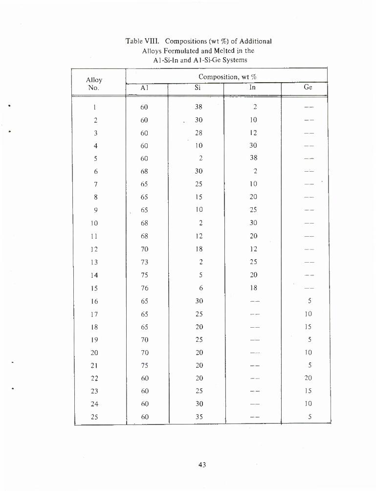
Table VIII. Compositions (wt %) of Additional Alloys Formulated and Melted in the
Al-Si-In and Al-Si-Ge Systems
Alloy No.
Composition, wt %
Al Si In Ge
1 60 38 2 —
2 60 30 10 —
3 60 28 12 —
4 60 10 30 —
5 60 2 38 —
6 68 30 2 —
7 65 25 10 —
8 65 15 20 —
9 65 10 25 —
10 68 2 30 —
11 68 12 20 —
12 70 18 12 —
13 73 2 25 —
14 75 5 20 —
15 76 6 18 —
16 65 30 — 5
17 65 25 — 10
18 65 20 — 15
19 70 25 — 5
20 70 20 — 10
21 75 20 — 5
22 60 20 — 20
23 60 25 — 15
24 60 30 — 10
25 60 35 — 5
43
metal research since 930°F is in the right range for brazing the base metals 7075 and 2024. From the standpoint of braze metal-base metal interaction and flow, alloy No. 1 (61.5 Ag-25.7 Al-1 2.8 In, wt%) which brazed at 1075°F also looks very attractive.
Earlier in the program we found that magnesium-bearing experimental brazing alloys could not be melted using conventional arc-melting techniques. Later, we successfully developed techniques for preparing 10-gram buttons of several magnesium-bearing alloys. Pad tests using the lowest melting binary alloys were run at 930°F on 6061 pads. Flow of the experimental alloys was obtained in all three cases and the results were also very promising.
44
APPENDIX
INTRA-LABORATORY CORRESPONDENCE OAK RIDGE NATIONAL LABORATORY
March 10, 1971
TO: W.J.Werner, Bldg. 4508
FROM: JR. Stokely
Subject: Potential Measurements on Alloy Samples
Zero-current potential measurements were made on alloy samples as requested. Measurements were made on each sample under four different sets of experimental conditions. These conditions are listed below.
Series A. Sample as received. Electrolyte solutions: 1 _M sodium chloride. Argon atmosphere over solution.
Series B. Samples cleaned with acetone; then etched with 20% nitric acid-2% hydrofluoric acid. Electrolyte solution: 1 N1 sodium chloride. Argon atmosphere.
Series C. Sample ground to high polish and potential measured immediately. Electrolyte solution: 1 M sodium chloride. Argon atmosphere.
Series D. Sample cleaned with acetone and ground to high polish. Electrolyte: 1 ^1 perchloric acid. Argon atmosphere.
The potential of each alloy was recorded with time and, in most cases, it reached a steady value within ten minutes. A saturated calomel electrode, isolated from the solution by a salt bridge, was used as the reference electrode. A listing of the observed steady potentials is attached for your information.
It was observed that hydrogen was evolved at the alloy surface as the sample was placed in the electrolyte solution. Hydrogen evolution was most pronounced with perchloric acid as the electrolyte (Series D); the entire surface of the alloy was covered with gas bubbles within a minute or two. With sodium chloride as the electrolyte (Series A, B, and C), hydrogen evolution was not nearly as rapid but still was apparent after 5-10 minutes soaking in the solution.
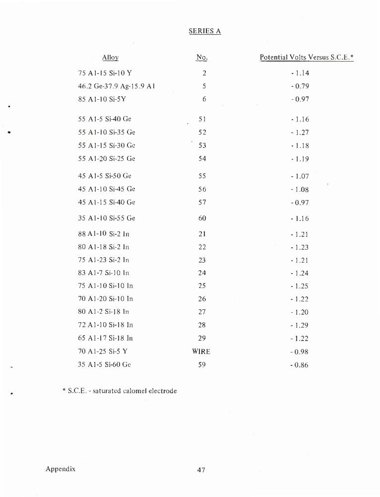
For Series A, B, and C (1 _M sodium chloride solution) reproducible potentials for the Al-Si-In alloys were obtained. Final steady potentials of from -1.20 to -1.29 v vs. S.C.E. (saturated calomel electrode) were observed with these alloys. No systematic change in potential was observed as the composition of the alloy was varied.
45
The potentials of the Al-Si-Ge alloys for Series A, B, and C are less negative than those for the Al-Si-ln alloys. Again, there does not appear to be a correlation between alloy composition and the measured potentials. The potentials of the Al-Si-Ge alloys vary from -0.92 to -1.19 v vs. S.C.E.
The potentials observed for most of the alloys in 1 M perchloric acid are about 0.2 v less negative than potentials observed with the sodium chloride solution. We think this difference is due to the higher hydrogen ion concentration in the solution. (As the hydrogen ion concentration becomes higher, a less negative potential would be required to reduce hydrogen ion to hydrogen gas).
Our conclusion involving these potential measurements is that we are measuring essentially the hydrogen ion-hydrogen gas potential at the surface of the alloy. Differences in potential within each series are probably due to differences in hydrogen over voltage with the alloys.
J. R. Stokely Analytical Chemistry Division
Appendix 46
SERIES A
Alloy No. Potential Volts Versus S.C.E.*
75 Al-15 Si-lOY 2 -1.14
46.2Ge-37.9 Ag-15.9 Al 5 -0.79
85 Al-10Si-5Y 6 -0.97
55 A1-5 Si-40Ge 51 -1.16
55 Al-10 Si-35 Ge 52 - 1.27
55 Al-15 Si-30Ge 53 - 1.18
55 Al-20Si-25Ge 54 - 1.19
45 Al-5Si-50Ge 55 - 1.07
45 Al-10 Si-45Ge 56 - 1.08
45 Al-15 Si-40Ge 57 -0.97
35 Al-10 Si-55 Ge 60 - 1.16
88 Al-10 Si-2In 21 - 1.21
80 Al-18Si-2In 22 - 1.23
75 A1-23 Si-2 In 23 - 1.21
83 Al-7 Si-lOIn 24 - 1.24
75 Al-10 Si-10 In 25 - 1.25
70Al-20Si-10In 26 - 1.22
80 Al-2 Si-18 In 27 - 1.20
72 Al-10 Si-18 In 2X - 1.29
65 Al-17 Si-18 In 29 -1.22
70 A1-25 Si-5 Y WIRE -0.98
35 A1-5 Si-60Ge 59 -0.86
* S.C.E. - saturated calomel electrode
Appendix 47
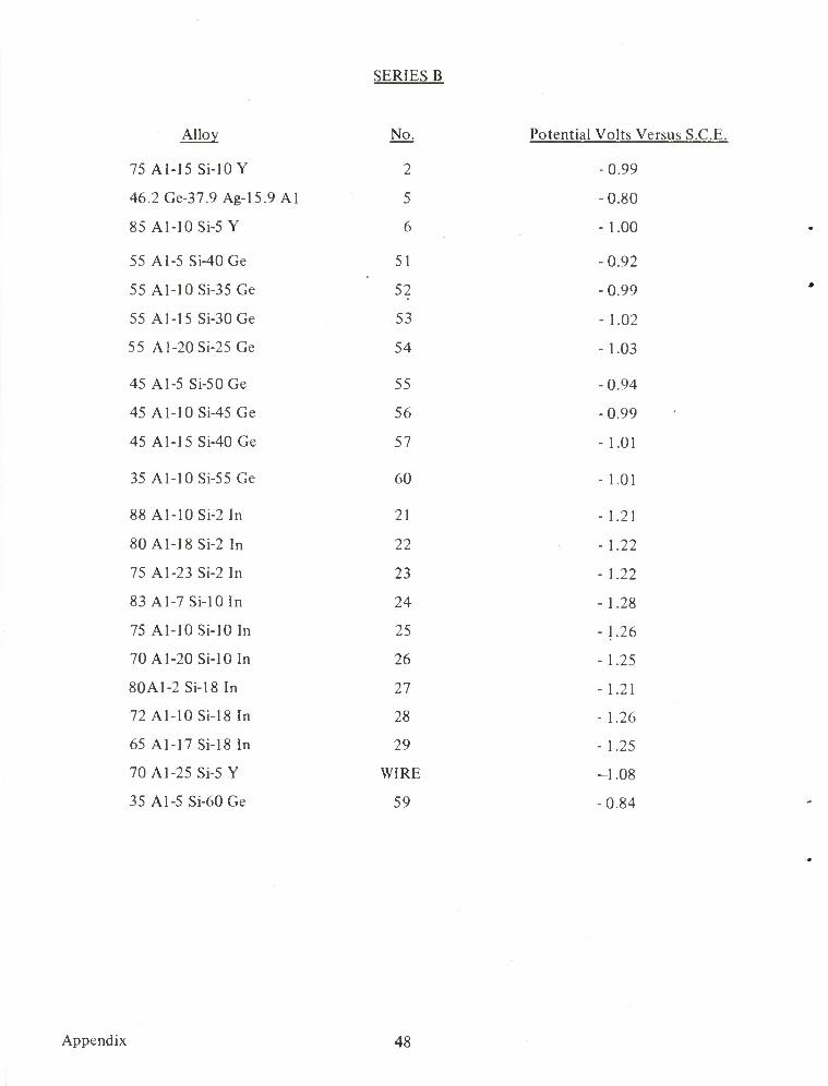
SERIES B
Alloy No. Potential Volts Versus S.C.E.
75 Al-15 Si-10 Y 2 -0.99
46.2Ge-37.9 Ag-15.9 Al 5 -0.80
85 Al-10Si-5 Y 6 - 1.00
55 A1-5 Si-40Ge 51 -0.92
55 Al-10Si-35 Ge 52 -0.99
55 Al-15 Si-30Ge 53 - 1.02
55 Al-20Si-25 Ge 54 - 1.03
45 A1-5 Si-50Ge 55 -0.94
45 Al-10Si-45Ge 56 -0.99
45 Al-15 Si-40Ge 57 - 1.01
35 Al-10Si-55Ge
88 Al-10 Si-2 In
80 Al-18 Si-2 In
75 A1-23 Si-2 In
83 A1-7 Si-10 In
75 Al-10 Si-10 In
70Al-20Si-10In
80 A1-2 Si-18 In
72 Al-10 Si-18 In
65 Al-17 Si-18 In
70 A1-25 Si-5 Y
35 A1-5 Si-60Ge
60
21
22
23
24
25
26
27
28
29
WIRE
59
- 1.01
-1.21
- 1.22
- 1.22
- 1.28
- L26
-1.25
- 1.21
- 1.26
- 1.25
-1.08
-0.84
Appendix 48
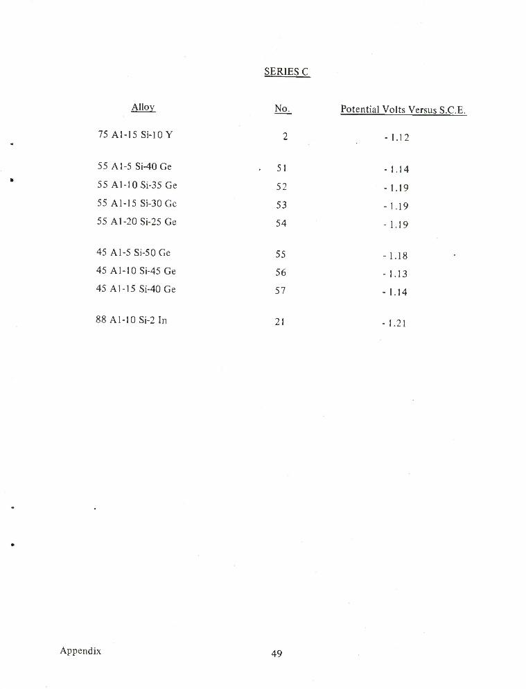
SERIES C
Alloy
75 Al-15 Si-lOY
55 Al-5 Si-40Ge
55 Al-10Si-35Ge
55 Al-15 Si-30Ge
55 Al-20Si-25Ge
45 Al-5 Si-50Ge
45 Al-10Si-45Ge
45 Al-15 Si-40Ge
88 Al-10Si-2In
No.
2
51
52
53
54
55
56
57
21
Potential Volts Versus S.C.E.
-1.12
-1.14
-1.19
-1.19
-1.19
-1.18
-1.13
- 1.14
- 1.21
Appendix 49
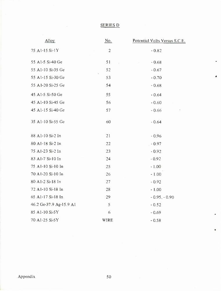
SERIES D
Alloy No.
75 Al-15 Si-IY 2
55 A1-5 Si-40Ge 51
55 A1-10 Si-35 Ge 52
55 Al-15 Si-30Ge 53
55 Al-20Si-25Ge 54
45 A1-5 Si-50Ge 55
45 Al-10Si-45Ge 5h
45 Al-15 Si-40Ge 57
35 Al-10Si-55Ge 60
88 Al-10Si-2In 21
80 Al-18 Si-2 In 22
75 A1-23 Si-2 In 23
83 Al-7 Si-lOIn 24
75 Al-10 Si-10 In 25
70 Al-20Si-10In 26
80Al-2Si-18In 27
72 Al-10 Si-18 In 28
65 Al-17 Si-18 In 29
46.2Ge-37.9 Ag-15.9 Al 5
85 Al-10 Si-5Y 6
70 A1-25 Si-5Y WIRE
Potential Volts Versus S.C.E.
-0.82
-0.68
-0.67
-0.70
-0.68
-0.64
-0.60
-0.66
-0.64
-0.96
-0.97
-0.92
-0.92
- 1.00
-1.00
-0.92
- 1.00
-0.95,-0.90
-0.52
-0.69
-0.58
Appendix 50
DISTRIBUTION LIST
Agency Copies
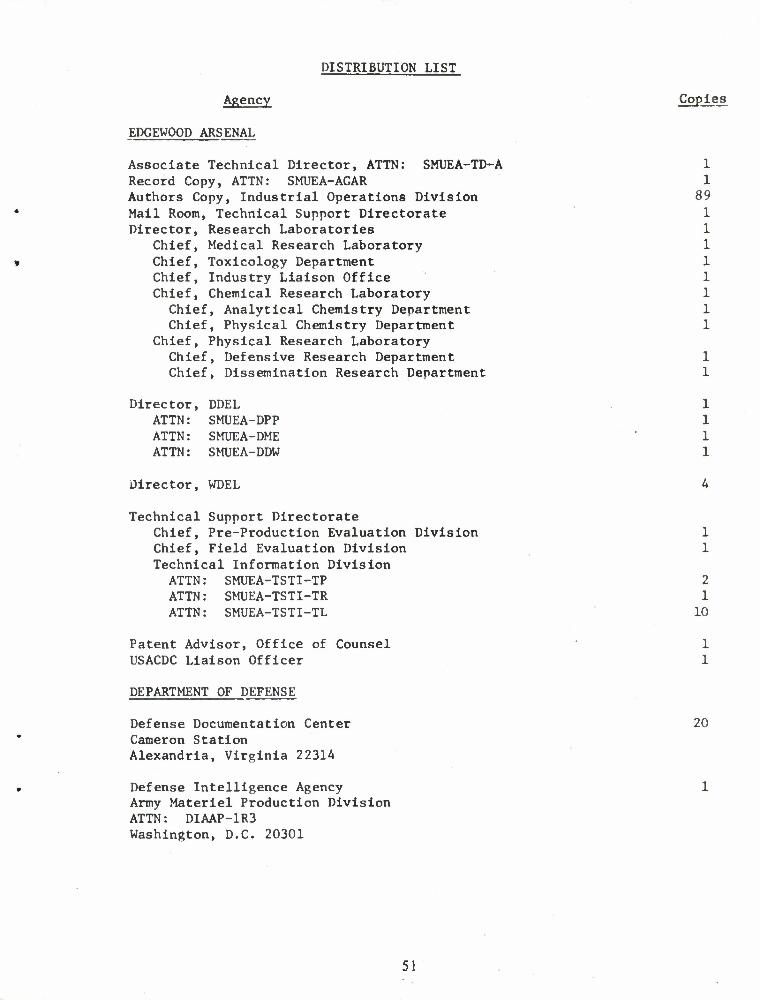
EDGEWOOD ARSENAL
Associate Technical Director, ATTN: SMUEA-TD-A 1 Record Copy, ATTN: SMUEA-AGAR 1 Authors Copy, Industrial Operations Division 89 Mail Room, Technical Support Directorate 1 Director, Research Laboratories 1
Chief, Medical Research Laboratory 1 Chief, Toxicology Department 1 Chief, Industry Liaison Office 1 Chief, Chemical Research Laboratory 1
Chief, Analytical Chemistry Department 1 Chief, Physical Chemistry Department 1
Chief, Physical Research Laboratory Chief, Defensive Research Department 1 Chief, Dissemination Research Department 1
Director, DDEL 1 ATTN: SMUEA-DPP 1 ATTN: SMUEA-DME 1 ATTN: SMUEA-DDW 1
Director, WDEL A
Technical Support Directorate Chief, Pre-Production Evaluation Division 1 Chief, Field Evaluation Division 1 Technical Information Division ATTN ATTN ATTN
SMUEA-TSTI-TP 2 SMUEA-TSTI-TR 1 SMUEA-TSTI-TL 10
Patent Advisor, Office of Counsel 1 USACDC Liaison Officer 1
DEPARTMENT OF DEFENSE
Defense Documentation Center 20 Cameron Station Alexandria, Virginia 22314
Defense Intelligence Agency 1 Army Materiel Production Division ATTN: DIAAP-1R3 Washington, D.C. 20301
51
DISTRIBUTION LIST (Contd)
Agency Copies
Director, Technical Information 1 Advanced Research Projects Agency Office, Secretary of Defense The Pentagon Washington, D.C. 20301
ATOMIC ENERGY COMMISSION
Los Alamos Scientific Laboratory 1 P.O. Box 1663, ATTN: Report Librarian Los Alamos, New Mexico 87544
DEPARTMENT OF THE ARMY
Department of the Army Office, Chief of Research & Development 1 ATTN: OCRD-CRDNCB Washington, D.C. 20310
Headquarters 1 Department of the Army, 0ACSF0R ATTN: FOR CM SR Washington, D.C. 20310
Director of CBR & Nuclear Operations, OACSFOR 1 Department of the Army ATTN: Mr. N. E. Sills Washington, D.C. 20310
Commanding Officer US Army Limited War Laboratory
ATTN: CRD-AM-7C 1 ATTN: CRD-AM-7A 1
Aberdeen Proving Ground, Maryland 21005
US ARMY MATERIEL COMMAND
Commanding General US Army Materiel Command
ATTN: AMCAD-S 1 ATTN: AMCRD-BC 1 ATTN: AMCRD-TC 1 ATTN: AMCMA-DA 1
Washington, D.C. 20315
52
DISTRIBUTION LIST (Contd)
Agency Copies
Commanding General 1 US Army Test & Evaluation Command ATTN: AMSTE-NB Aberdeen Proving Ground, Maryland 21005
Director 1 Army Materials & Mechanics Research Center ATTN: AMXMR-ATL Watertown, Massachusetts 02172
US Army Missile Command 2 Redstone Scientific Information Center ATTN: Chief, Document Section Redstone Arsenal, Alabama 35809
Commanding Officer 1 Rocky Mountain Arsenal Denver, Colorado 80240
Commanding General 2 Deseret Test Center ATTN: STEDP-MS-TI Dugway, Utah 84022
Commanding General US Army Natick Laboratories 1 ATTN: Technical Library Natick, Massachusetts 01760
Commanding Officer 1 Aberdeen R&D Center ATTN: AMXRD-T, William Kolinakis Aberdeen Proving Ground, Maryland 21005
US Army Mob Equip Res & Dev Center 1 ATTN: Tech Documents Ctr, Bldg 315, Vault Fort Belvoir, Virginia 22060
Commanding Officer 1 ATTN: Technical Library Aberdeen Proving Ground, Maryland 21005
US ARMY MUNITIONS COMMAND
Commanding Officer 1 Picatinny Arsenal ATTN: SMUPA-VL Dover, New Jersey 07801
53
DISTRIBUTION LIST (Contd)
Agency Copies
Commanding General US Army Munitions Command
ATTN: AMSMU-QA 1 ATTN: AMSMU-RE-R 1 ATTN: AMSMU-RE-N 1 ATTN: AMSMU-SS-SC 1
Dover, New Jersey 07801
Commanding Officer US Army Frankford Arsenal
ATTN: SMUFA-U2100 1 ATTN: C2500 - Library 1
Philadelphia, Pennsylvania 19137
Commanding Officer 1 Pine Bluff Arsenal ATTN: Director of Chemical Operations Pine Bluff, Arkansas 71601
Hq, USA MUCOM 1 ATTN: AMSMU-LB USAMMCS-LN 0 Picatinny Arsenal Dover, New Jersey 07801
CONARC
Commandant 2 US Army Missile & Munitions Center & School ATTN: AJO-UE Redstone Arsenal, Alabama 35809
COMBAT DEVELOPMENT COMMAND
Commanding Officer 1 US Army Combat Development Command ATTN: Combat Support Group Fort Belvoir, Virginia 22060
Commanding Officer 1 USACDC Maintenance Agency ATTN: CDCMA-A (Library) Aberdeen Proving Ground, Maryland 21005
Commanding Officer 1 USACDC Aviation Agency Building 506 Fort Rucker, Alabama 36360
54
DISTRIBUTION LIST (Contd)
Agency Copies
Commanding Officer 1 USACDC Special Warfare Agency ATTN: Chemical Advisor Fort Bragg, North Carolina 28307
Commanding General 1 USACDC Experimentation Command ATTN: CDEC-AG Fort Ord, California 93941
Executive Officer 1 USACDC Institute of Nuclear Studies Fort Bliss, Texas 79916
DEPARTMENT OF THE NAVY
Chief, Office of Naval Research 1 Department of the Navy ATTN: Code 454 Washington, D.C. 20360
Director 1 US Naval Research Laboratory ATTN: Code 1031, Army Lia Ofcr Washington, D.C. 20390
US Naval Applied Science Laboratory 1 ATTN: Code 944 Naval Base Brooklyn, New York 11251
Commander (Code 753) 1 Naval Weapons Center ATTN: Technical Library China Lake, California 93555
Commanding Officer ATTN: Army Chemical Office 1 US Naval Explosive Ordnance Disposal Facility Indian Head, Maryland 20640
Commander 1 US Naval Weapons Laboratory ATTN: Code WWB Dahlgren, Virginia 22448
55
DISTRIBUTION LIST (Contd)
Agency
Officer in Charge Naval Material Industrial Resources Office Philadelphia, Pennsylvania 19112
DEPARTMENT OF THE AIR FORCE
AFRPL (RPC) ATTN: Chief, Propellant Division Edwards AFB, California 93523
ADTC (ADAM) Eglin AFB, Florida 32542
Commander Foreign Technology Division ATTN: TDEWA Wright-Patterson AFB, Ohio 45433
Headquarters Aerospace Medical Division (AMRS) Brooks Air Force Base, Texas 78235
Air Force Armament Labs (ATCE) Chief, Non-Explosive Munitions Division (ATM) Eglin AFB, Florida 32542
DISTRIBUTION LIST FOR DD 1473's
Copies
1
Chief of Research and Development Headquarters, Dept. of the Army ATTN: Director of Army Technical Information Washington, D.C. 20310
Technical Support Directorate ATTN ATTN ATTN
SMUEA-TSTD SMUEA-TSTI-TP SMUEA-TSTI-TL
1 1 2
56
UNCLASSIFIED W<»/tlT CUlKfllllK.
DOCUMENT CONTROL DATA KID jjjjgjjMj tlKiMkNtoW >m». W^> W jtgg I immMii »•—» W gjijggJ g#g g>* fgjjg r»f r< l« lUillf*}
I I
». c«^iM4i^« ACiiwii* (Cm
CO. tdgev. ood Arsenal •' ATTN: SMUEA-TMO-MS Edgcwood Anenal. Maryland 21010
UNCLASSIFIED
NA » »*»o»f «mi
THE DEVELOPMENT OF FILLER METAL ALLOYS FOR VACUUM BRAZING-GAS QUENCHING OF ALUMINUM ALLOYS
• 9«KM»1I*I »O1*»(Ttm0 mltmpmn mm* ktkllMMN)
The program was started in April 1969 and concluded in December 1970. i tSTSSSSSmTJFBmTmmZSBBC BPBC t—« ——j
William J. Werner, and Gerry M. Slaughter
November 1971 >«. Tot»«. MO. or »••••
58 Im. (»t»CI OO t*MT MO.
•.•MMCTNo. 4932-10-51129
Mb «»m««i«r» •I'om NtlMMMM
>• wt wiuiioo ixrivfar
Approved for public release; distribution unlimited.
hl'XIMOllMT wet ST
Vacuum brazing-gas quenching of chemical and related munitions^^ £j£t itf^f'
it. »»o~»<j"i««« Mti >T*av ten* <f
i7 >l I1W1TCT
"ottrib program. m developed .several aluminum-silicon base brazing Tiller metal composilionsthat appear to exhibit significant improvements over existing commercial compositions. They braze in vacuum at temperatures lower than the flow temperatures of commercial brazing alloys, and have equal or better flowabflity. GUffjowest flow temperature for these alloys - !02C'F - is about 50*F lower than the generally accepted*flow temperature of the Alcoa No. 718 (88 AM 2 Sf. wtffc) commercial alloy./ All of these compositions flowed on aluminum alloy 6061 in vacuum without the use of flux. The Al-S»-In ' alloys exhibited flow temperatures in the range 1075* to I095*F. and the Al-Si-Y alloys exhibited flow -; temperatures in the range 1095° to I I40*F. Alloys in the AI-Si-Ge system were particularly promising and / exhibited flow temperatures of 1020" to I095*F. Of particular interest in this system are the 55 AI-5 SH»(/ Ge. 45 AI-5 St-50 Ge. and 35 AI-5 Si-60 Ge (wt%) aUoys all of which flowed at I020*F; these flow temperatures are approximately 50*F below those of commercial alloys. It should be emphasized at this point that we feel that the full potential of these alloys is yet to be realized. That is, further work is necessary to show that the optimum compositions in these systems have been found. Secondly, further minor additions of other elements such as Cu. Zn, Sn, etc.. should be investigated since they may result in further flow temperature reductions and/or wettability-ftowability improvements. Also, optimum time-temperature relationships for vacuum brazing with these alloys must be established. The silver-bearing ternary and quaternary experimental brazing filler metals were also formulated, melted, and tested on 6061 base metal lor wetting and flow properties. It should be emphasized that the Ag-AI-Ge ternary alloy (alloy No. 5. 37.9 Ag-15.9 AI-46.2 Ge, wt%) had a flow temperature of approximately 930*F. This is a significant break-through in aluminum brazing filler metal research since 930 F is in the right range for brazing the base metals 7075 and 2024, From the standpoint of braze metal-base metal interaction and flow, alloy No. I (615 Ag-25.7 AM 2A In. wt9f) which brazed at 1075°F also looks very attractive. Earlier in the program
DD/r\.1473 TsmwzsKU •«T». I «• mm, men ••
UNCLASSIFIED
-- •'- i ;• »
UNCLASSIFIED Security Classification
KEV WORD!
we found that magnesium-bearing experimental brazing alloys could not be melted using conventional arc-melting techniques. Later, we successfully developed techniques for preparing 10-gram buttons of several magnesium-bearing alloys. Pad tests using the lowest melting binary alloys were run at 930°F on 6061 pads. Flow of the experimental alloys was obtained in all three cases and the results were also very promising.
14. KEYWORDS
Vacuum brazing Gas quenching Aluminum alloys 6061, Aluminum - silicon-indium Aluminum-silicon-germanium system Aluminum-silicon-yttrium system Magnesium-bearing alloys Silver-bearing alloys
2219, 7075, systems
2024
58 UNCLASSIFIED Security Classification