the dinosaur bridge innovation in structural form
TRANSCRIPT

SEI Special Issue November 2021: Technical Report 2161 words
The Dinosaur Bridge – innovation in structural form &
fabrication using model making and prototyping
Authors: David KNIGHT1, Stuart CHAMBERS2, Mike TONKIN3
Affiliation: 1 Director of Design & Engineering, Cake Industries, London, UK –
2 Senior Structural Engineer, Arup, London, UK - [email protected]
3 Director, Tonkin Liu, London, UK – [email protected]
Abstract
While small, the Dinosaur Bridge demonstrates how close collaboration between the design and
fabrication team and a rigorous process of modelmaking and prototyping can create a delicate
structure that suggests new ways of generating sculptural form.
A team of Tonkin Liu (architects), Arup (structural engineering) and Cake Industries (fabrication and
installation) were commissioned by the charitable body that looks after the Victorian Dinosaur
sculptures in Crystal Palace Park, London, to improve access for maintenance and educational
purposes to the heritage island. By drawing on and abstracting references from the natural world,
the team developed a scheme for an eight metre swing bridge that creates a complex sculptural
geometry from flat laser cut steel sheet. By cutting a “comb” from a 10mm thick plate, the cantilever
struts, deck stiffeners and balustrade posts could all be folded from a single piece. This framework is
attached to a triangular and profiled box girder, creating a structure that is visually striking, with
sinusoidal forms that act both visually and structurally.
This paper describes the collaborative process of developing the design through understanding and
incorporating the fabrication process in the design concept, and working at various physical model
scales through to full size testing. The bridge is due to be installed in autumn 2020.
Keywords: structural concepts; planning; fabrication; structural models, moving structures;
aesthetics; community funding
Introduction and Project Background
The life-sized sculptures of Dinosaurs [Figure 1] located in Crystal Palace Park, London, were
created at a pivotal moment as the first ever “edu-tainment for science”. Set in landscapes that
attempt to reflect 400 million years of geologic time as light-touch experiential learning, the
ensemble has significant heritage value and embodies the democratisation of scientific knowledge.
The Dinosaurs were built in Crystal Palace Park in 1854 as it was being developed to surround a re-
built and expanded version of the Great Exhibition of 1851 [Figure 2].

Figure 1. The Crystal Palace Park Dinosaurs now [credit: Friends of Crystal Palace Dinosaurs].
Figure 2 Crystal Palace with the Dinosaur sculptures in 1854 [credit: Friends of Crystal Palace Dinosaurs].
To access the island easily, a bridge was required. The Friends of Crystal Palace Dinosaurs, a local
charity, instigated a campaign to build a new bridge that would facilitate the restoration of the
concrete sculptures of dinosaurs and other extinct animals and open up the island as an educational
resource.
Design
Given the limited project budget and strong visual requirements that come from building adjacent to
a highly sensitive heritage site, the design of the bridge had to be undertaken collaboratively. Tonkin
Liu, Arup and Cake Industries worked together through multiple design workshops to develop a
scheme that married form, structure and fabrication, within a miniscule budget.
The bridge is positioned at the southern end of the Dinosaur Islands, in the ‘deepest’ part of the
geological walk through time. This is where the sculptures of the earliest land vertebrates emerge
from the metaphorical and actual waters. Inspired by the skeletal structures of fish that dominated
the early seas the bridge features a ‘linear spine’ that supports a cut steel plate from which a series
of ‘ribs’ are folded which support the bridge deck and the handrail. Like a living animal, it moves,
rotating into its active or inactive position. The bridge features organic and curved components,
similar to geometries found in nature, that are shaped to provide structural support and stability
[Figure 3].

Figure 3. The development of the form from a straight horizontal bridge to one where the form provides
strength and stability; load is concentrated towards the centre of the bridge’s spine beam and an undulating
geometry provides strength and stability to the handrail. [credit: Tonkin Liu]
Model making and prototyping
The major innovation within the design of the structure involved the use of a folded comb [Figure 4]
that acts as both the deck plate, the struts supporting the edge of the deck, and also the balustrade
post. A series of models were used by Tonkin Liu to test the structural principles of the ‘comb’
concept during early design stages. The first model that explored the deck was a simple paper model
that made an unfolding comb. This was followed by a quick straw model [Figure 5] that tested the
notion that a curving profile would add stability to the balustrade and deck. The models
demonstrated compression in the downward struts and tension in the deck.

Figure 4. The ‘folded comb process’ provided deck, strut and handrail elements from a single sheet of steel
[credit: Tonkin Liu].
Figure 5. Preliminary model using straws [credit: Tonkin Liu]

Figure 6. Preliminary model using etched thin metal [credit: Tonkin Liu]
Structural models are quick and easy to put together and demonstrate behaviour in a simple way.
Modern modelmaking techniques also make it simple to replicate the process of CNC cutting plate
materials [Figure 6] and can create beautiful architectural models that serve multiple purposes –
both indicating the final appearance to funders and the public as well as demonstrating the
complexities of some geometrical ideas. Tonkin Liu created a 1:20 scale laser etched model [Figure
7] that was exhibited at the Royal Academy Summer Exhibition 2019 (winning the BKI Material
Prize). This model was a useful staging post in the design process and led to changes in the overall
form, simplifying and slimming the visual impact.
Figure 7. Model exhibited at the Royal Academy Summer Exhibition 2019 [credit: Tonkin Liu]
The folded-comb process was prototyped at Cake Industries [Figure 8] using mild steel sheets to
ensure that the process was feasible before it was incorporated in the final design. This prototyping
allowed the definition of appropriate tolerance limits and bend criteria to be fed into the Arup
structural model to check the buckling and strength capacities of the various elements. It also
allowed the fabricator to determine the exact manufacturing process and element spacings to meet
the workshop requirements.

Figure 8. Full scale prototype supporting the team (David Knight, Keefer Erickson, Stuart Chambers, Anna
Liu, Mike Tonkin, Matthew Burnett) [credit: Cake Industries]
This loop of design to modelmaking to feedback to prototyping to feedback to final scheme design
allowed the design team to become confident enough to implement an innovative and untried
fabrication process in the final scheme.

Final Scheme
Figure 9. The handrail derives stiffness through the geometry of the comb sections, having a push pull offset
along the length of the bridge [credit: Tonkin Liu/Arup]
For the completed Dinosaur Bridge, a single flat sheet of 10mm thick steel was laser cut with a comb
pattern. The deck struts (36mm wide) and balustrade posts (31mm wide) were bent out of the plane
of this sheet by heating the root of the tine using an oxyacetylene torch, taking care to heat to
within the limits for hot working in EN1090-2 (i.e. 600 to 650 degrees). The tine could then be bent
by hand to an orientation to suit the final geometry. A 50mm wide deck edge was left attached to
the 36mm wide deck cross pieces to tie the system together. A simple expanded steel mesh is
incorporated on the deck to create a walking surface.
The spine of the bridge is supported on a single central support that would allow it to rotate on
plan, blocking access to the Dinosaurs when spun away from the bank whilst allowing access for
maintenance and visitors when in its service position [Figure 9]. In the service position, the bridge
does not rest on the banks; it remains supported only by the central support.
The greatest structural forces occur at the central support and the profile of this spine is optimised
to be deepest and widest at the centre and to curve upwards and outwards to the two landing
points. This curving profile and triangular cross section give the beam maximum strength and
stiffness for the minimum amount of structural material as it delivers loads directly to the central
bearing. The longitudinal bending forces are primarily taken in the triangular box cross section, but
due to the fully welded nature it was important to account for the parasitic stresses that the parapet
posts and handrail carry.
The central spine beam is supported by the bearing and in turn supported the comb sections, which
act somewhat independently of the spine. Out of balance force over the width of the deck are dealt
with through torsion in the spine beam, while out of balance force over the length of the bridge are
dealt with through the bending strength of the spine beam, transferring the overturning forces to the
bearing and foundation.

The handrail derives stiffness through its undulating geometry. Utilising vierendeel action in
balustrade sections to transfer the shear force, the handrail system generates a lever arm at its base
that allows it to resist the overturning force generated by people pushing or pulling the handrail.
A project of this nature was bound to go through several design iterations until the desired outcome
was achieved. To streamline the process Arup generated a parametric script utilising Rhino,
Grasshopper and plugin Geometrygym [Figure 10], which allowed the rapid build and test of a
multiple analysis models. Parameters such as section size, fabrication thickness, amplitude, repetition
of wave form, hierarchy of elements, and so on were varied and studied, with feedback from the
physical modelling fed into the process.
Figure 10. Grasshopper and Geometrygym used for rapid generation of varying analysis geometries [credit:
Arup]
These studies allowed the team to determine rapidly and accurately the most efficient yet visually
appealing forms. They demonstrated that for this system there was a delicate balance between the
force distribution in elements of the bridge and the regularity of their repetition. It transpired that
(similar to a bicycle wheel) by using many slender elements all acting together, the bridge could in
fact achieve higher resistance than it would if using fewer larger elements, where force would
ultimately concentrate and overload a single element of the comb.
Whilst there was a desire to utilise the thinnest possible steel plate to maximise buildability and
minimise material use, the bending forces induced by a point load on the deck had a significant
impact on the stresses of the deck elements. A balance was struck with 10mm as it offered a plate
thickness that could still be bent during fabrication but allowed the deck widths desired.
The bridge, having relatively little mass, is highly susceptible to footfall-induced vibrations. The
connection detailing from spine beam to bearing has a considerable impact on the stiffness and
vibrational performance, commensurate with the depth and thickness of the spine beam. The bridge
form was tailored to maximise stiffness to combat these effects.
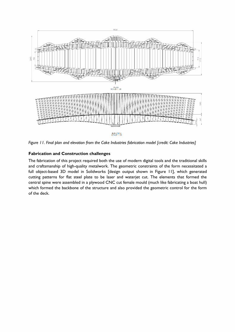
Figure 11. Final plan and elevation from the Cake Industries fabrication model [credit: Cake Industries]
Fabrication and Construction challenges
The fabrication of this project required both the use of modern digital tools and the traditional skills
and craftsmanship of high-quality metalwork. The geometric constraints of the form necessitated a
full object-based 3D model in Solidworks [design output shown in Figure 11], which generated
cutting patterns for flat steel plate to be laser and waterjet cut. The elements that formed the
central spine were assembled in a plywood CNC cut female mould (much like fabricating a boat hull)
which formed the backbone of the structure and also provided the geometric control for the form
of the deck.

Figure 12. Fabrication underway in the Cake Industries workshop: heating combs prior to manually bending
[credit: Cake Industries]
Figure 13. Fabrication underway in the Cake Industries workshop: welding deck to the spine beam; [credit:
Cake Industries]
The deck combs were formed using a manual two stage process. Deck struts and balustrade posts
were bent to an intermediate position [Figure 12] to allow the segments to be offered up to the
central core [Figure 13], before a secondary process was used to bend the tine to exactly the
correct location at the bottom of the spine beam or where it intersected with the handrail line. This

process allowed the craft skills of the makers to focus on forming smooth curved lines within the
structure rather than concentrating on absolute dimensional accuracy [Figure 14].
Cost
This project was undertaken by the design and fabrication team as a charitable exercise, working
closely with the client who are a local volunteer organisation dedicated to looking after the Crystal
Palace Dinosaurs. The funding for the project was raised from charitable grants and local people
through a crowdfunding process and therefore the design and build budget was necessarily
constrained, with under £100,000 being available to construct the bridge. Donations of time and
fabrication space by Tonkin Liu, Arup and Cake Industries made up the shortfall in cost.
Galvanising
With an overall form that consists of small thin elements, designing for the durability of the structure
was a key process. Stainless steel was considered as a possibility but was precluded by the minuscule
fabrication budget. Instead, the visual and protective finish for the structure was applied in a single
action by hot dip galvanising the entire structure [Figure 15]. This required the use of the largest
galvanising bath in Great Britain, located in Chesterfield and operated by Joseph Ash.
Considerable design effort was put into ensuring that the overall height of the structure including the
integral parapets and handrail was smaller than the width of the bath (1700mm). As the final height
was only 60mm smaller than this, additional measures had to be put in place by the galvaniser to
prevent the presence of impurities on the surface of the bath discolouring the final finish. This
include the provision of additional operatives to scrape the bath surface and “air lance” the piece as
it was removed from the bath. Drainage holes were provided throughout the core to allow free
drainage of zinc through the structure. It is expected that no further maintenance to the finish will
be required for the lifetime of the structure.
Figure 14. Transportation from the fabrication yard to galvanisers, showing sinuous form [credit: Cake
Industries]
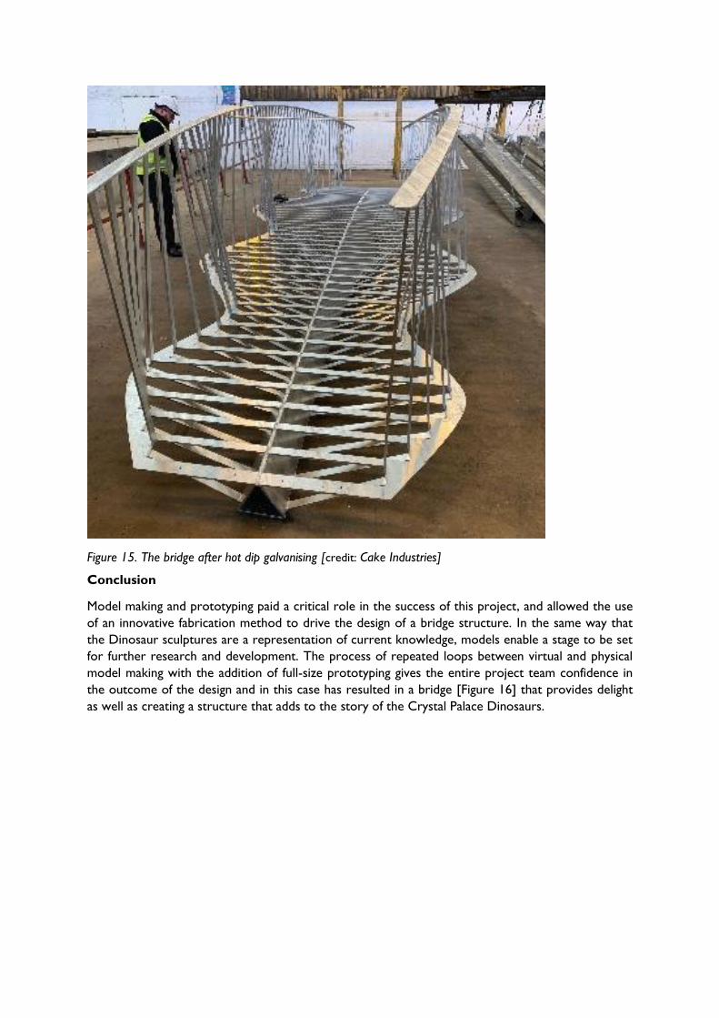
Figure 15. The bridge after hot dip galvanising [credit: Cake Industries]
Conclusion
Model making and prototyping paid a critical role in the success of this project, and allowed the use
of an innovative fabrication method to drive the design of a bridge structure. In the same way that
the Dinosaur sculptures are a representation of current knowledge, models enable a stage to be set
for further research and development. The process of repeated loops between virtual and physical
model making with the addition of full-size prototyping gives the entire project team confidence in
the outcome of the design and in this case has resulted in a bridge [Figure 16] that provides delight
as well as creating a structure that adds to the story of the Crystal Palace Dinosaurs.

Figure 16. Rendering of the Final Scheme [credit: Tonkin Liu]
SEI data block
Owner: Bromley Borough Council
Client: Friends of Crystal Palace Dinosaurs
Architect: Tonkin Liu
Structural Engineer: Arup
Main Contractor, fabricator and temporary works: Cake Industries
Plate cutting and profiling: M-Tec
Galvanising: Joseph Ash Galvanising
Piling and foundations: Capital Piling
Lifting subcontractor: City Lifting