the edge is our inspiration - capital safety · 2 work on the edge with confidence sharp edges are...
TRANSCRIPT

THE EDGE IS OURINSPIRATION
G L O B A L L E A D E R I N F A L L P R O T E C T I O N

2
WORK ON THE EDGE WITH CONFIDENCE
Sharp edges are found in many leading edge applications where the edge is able to cut or damage a traditional lifeline upon contact. Typical I-beams have edge radii that range from .005" (.13 mm) to .032" (.813 mm). Do you know how sharp your edges are?
.020" (.50 mm) equivalent to EN360 Sheet 60*
A
.005" (.13 mm) ANSI Z359.14
.010" (.25 mm)
B
.015" (.38 mm)
CD
WHAT YOU NEED TO KNOW WHEN IT COMES TO FALL PROTECTIONMany personal fall arrest systems rely on lifeline materials to perform under less than ideal conditions. But there are some applications where use of the wrong product—for example, where a lifeline contacts with a sharp edge—could have catastrophic results.
Product testing and certification organizations in the U.S. and around the world, including the American National Standards Institute (ANSI), the Canadian Standards Association (CSA) and CE in Europe, have been re-examining how lifelines in fall protection systems perform when subjected to these “sharp edge” applications. They’ve also placed a new focus on “leading edge” applications. Through this analysis, they have concluded that these two environments are unique in fall protection and involve increased risks due to the lifeline cutting, fraying or becoming otherwise compromised.
UNDERSTANDING LEADING AND SHARP EDGES
Leading Edge: To visualize a leading edge, imagine a worker installing steel decking on a new building. Now imagine the worker’s fall protection system is anchored at foot level behind him. As the worker moves out and away from the anchor point while installing the decking, the worker is exposed to a potential fall over the edge of the building or the edge of an elevated platform.
Sharp Edge: A sharp edge is one that, for practical purposes, is not rounded and has the potential to cut most types of lifelines. The ANSI standard for sharp edges, for example, involves testing the fall arrest device’s lifeline over a piece of steel bar with a radius of no more than 0.005” (5 one thousands of an inch). If the lifeline is cut or severely damaged, the device fails the test and does not comply with ANSI.

3
UNIQUE RISKS OF LEADING AND SHARP EDGE APPLICATIONS• Increased Fall Distance: When workers are attached at foot level, as they often are in leading edge
applications, they will fall farther than they would if they were anchored at shoulder height or above. The required clearance when anchored at foot level varies by product so make sure to reference the product instructions.
• Lock-up Speed: Self-retracting lifelines react to a fall when the lifeline accelerates out of the housing at a certain velocity, generally about 4.5 feet per second. When self-retracting lifelines are anchored at foot level, the lifeline does not achieve the required acceleration during a fall until after the user’s D-ring passes over the leading edge and below the level of the anchor. This means the user has already fallen about 5 feet before the self-retracting lifeline device will engage to arrest the fall.
• Increased Fall Arrest Forces: Falling further means the impact on the body through the fall protection system will potentially be higher when the fall is arrested. This is why many leading edge and sharp edge rated products contain additional energy-absorbing devices.
• Increased Potential for Swing Hazards: Depending on a worker's position when he falls, he may swing like a pendulum after the fall is arrested. While swinging is a hazard under any circumstances, the danger is compounded if the worker’s lifeline is strung taught over a sharp edge and saws back and forth across that edge.
NEW STANDARDS CALL FOR DIFFERENT EQUIPMENTPreviously, the industry made attempts to prevent hazards in sharp and leading edge applications. These solutions included attaching an energy absorber to standard self-retracting lifelines, protecting edges and elevating anchor points. While these efforts have been helpful, many organizations have now incorporated leading edge/sharp edge criteria into their standards, or are working toward this. This includes ANSI, CSA and CE standards for self-retracting devices. Through their testing and analysis, ANSI confirmed a number of assumptions, including the fact that products not specifically designed for foot level tie-off—the type of anchoring most often used in these applications—will generate forces far exceeding accepted safety parameters in the event of a fall. Therefore, standard fall protection equipment may not be acceptable for leading or sharp edge applications, according to ANSI. In August 2012, ANSI released a new standard—ANSI Z359.14 on Self Retracting Devices (SRDs)1—to address leading edge or sharp edge applications for self-retracting devices (SRDs). The Z359.14 standard includes significant changes to the design and testing of leading edge (LE) SRDs. It provides a baseline for manufacturers to test their products against, in order to ensure they are safe and compliant.2 It also requires manufacturers to provide new information in product user instructions and on product markings.
1 ANSI/ASSE Z359.14-2012 Safety Requirements for Self-Retracting Devices for Personal Fall Arrest & Rescue Systems, American Society of Safety Engineers (ASSE), http://www.asse.org. Accessed 12/9/14.
2 “Standard/Regulation Information, Safety Requirements for Self-Retracting Devices ANSI Z359.14-2012,” Capital Safety, http://api.capitalsafety.com/api/assets/download/1/9168257. Accessed 12/9/14.
Products not specifically designed for foot level tie-off will generate forces far exceeding accepted safety parameters in the event of a fall.
Leading and sharp edge components work together to absorb the energy, limiting the average arresting forces to 900 lb (4 kN) or less.
FORCE SHARP EDGES
Radius
as sharp as
.005" (.13 mm)
Traditional lifelines are simply unreliable over sharp edges.
Leading and sharp edge components work together to keep you safe in this dangerous and everyday situation.

4
Specifically designed for foot level tie-off.Nano-Lok edge takes the guesswork out of your work. Adhering to the most stringent standards, Nano-Lok edge is engineered to perform in the toughest sharp edge conditions. Why? Because on your job site, sharp edges are a reality, and you never know how sharp they are. Now you don’t have to.
FEATURES AND BENEFITS
• Integrated, backpack-style energy absorber: The energy absorber and connector work together to limit forces on both the worker and the impacted edge. Backpack design stays tight to the harness and evenly disperses the unit's weight.
• Easy-to-install connector: Providing 360 degrees of rotation, the direct-to-harness connection provides seamless integration of the energy absorber and leaves the D-ring open for rescue or other equipment.
• Global sharp edge icon: DBI-SALA universal icon to quickly and easily identify sharp edge product.
• Tough and flexible galvanized cable lifeline: The 8' (2.4 m) of 3/16" (5 mm) cable provides maximum range of motion, durability, and cut resistance.
• Impact-resistant housing: Lightweight thermoplastic housing provides maximum durability.
• Hook options: Designed to meet your unique needs, the Nano-Lok edge comes in many configurations.
DBI-SALA® NANO-LOK™ edge PERSONAL SRL
SOLUTIONS FOR LEADING AND SHARP EDGES
ACCESSORIES
3500046 Web D-ring Loop allows connection directly to D-ring
3100184 Pack Adaptor for harness with short back straps
NANO-LOK™ EDGE100% TIE-OFF UNIT

NANO-LOK EDGE SELECTION GUIDE
5
LIFELINE HOOK SRL
A. Ti
e-Ba
ck
B. A
lum
. Reb
ar
Lock
Hoo
k
C. S
teel
Reb
ar
Lock
Hoo
k
D. A
lum
. Reb
ar
Hook
E. S
teel
Reb
ar
H
ook
F. St
eel S
nap
Hook
G. S
teel
Swi
vel
Snap
Hoo
k
H. A
lum
. Cap
tive
Cara
bine
er
I. Al
um. S
nap
Hook U.S. PART
NUMBERCanada PART NUMBER
100%
Tie-
Off
n 3500228 3500235n 3500231 3500238
n 3500227 3500234n 3500249 3500250
n 3500246 3500253n 3500225 3500232
n 3500226 3500233n 3500229 3500236
n 3500230 3500237
Sing
le
n 3500213 3500220n 3500216 3500223
n 3500212 3500219n 3500247 3500251
n 3500248 3500252n 3500210 3500217
n 3500211 3500218n 3500214 3500221
n 3500215 3500222
DBI-SALA® NANO-LOK™ edge PERSONAL SRL
SOLUTIONS FOR LEADING AND SHARP EDGES
G Steel Swivel Snap Hook 3/4" (19 mm) gate opening.
H Aluminum Captive Carabiner 3/4" (19 mm) gate opening.
I Aluminum Snap Hook 1" (25 mm) gate opening.
C Steel Rebar Lock Hook 2 1/2" (63.5 mm) gate opening.
B Aluminum Rebar Lock Hook 2 1/2" (63.5 mm) gate opening.
A Tie-Back 3 ft. (.9 m) leg with 5000 lb (22 kN) gated hook. Creates a 9' (2.7 m) unit. Only available as specified models.
F Steel Snap Hook 3/4" (19 mm) gate opening.
D Aluminum Rebar Hook 2 1/4" (57 mm) gate opening.
E Steel Rebar Hook 2 1/2" (63.5 mm) gate opening. Creates a 7'4" (2.24 m) unit.
NANO-LOK™ EDGE SINGLE CABLE UNIT

Edge certified cable, 100% tie off, aluminum snap hook at all ends X 6ft
1246068 EZ-STOP LEADING EDGE 100% TIE-OFF
Engineered for work on sharp edges. Web and rope lanyards can break on sharp edges, such as I-beams or concrete. Work with confidence when you use the EZ-Stop Leading Edge, which provides steel cable foot-level tie-off for sharp edges.
FEATURES AND BENEFITS• Foot-level tie-offs for maximum 12ft free fall
• Quarter-inch vinyl-coated steel cable
• Many hook options, with lightest and strongest rebar hooks on the market
• Bright orange shock pack cover makes it easy to see you’re using a sharp-edge model
• Passes stringent ANSI Z359.14 (dropped on a .005 radius edge)
Edge certified cable, snap hook at one end, steel rebar (2 ½" gate opening) hook at other end X 6ft
1246261 EZ-STOP LEADING EDGE SINGLE CABLE UNIT
6
SPECIFICATIONS
USA Part # CA Part # Length Weight Size
1246261 1246261C 6 ft. (1.8m) 3.50 lbs (1.6kg) 6 ft. (1.8m)
1246068 1246068C 6 ft. (1.8m) 3.50 lbs (1.6kg) 6 ft. (1.8m)
1246066 1246066C 6 ft. (1.8m) 2.70 lbs (1.2kg) 6 ft. (1.8m)
1246178 1246178C 6 ft. (1.8m) 4.40 lbs (2.0kg) 6 ft. (1.8m)
1246067 1246067C 6 ft. (1.8m) 3.70 lbs (1.7kg) 6 ft. (1.8m)
DBI-SALA® EZ-STOP™ LEADING EDGE LANYARDS

7
Right-size gear works smarter, like you. That’s why we’ve expanded the Ultra-Lok leading edge product line to include a 15-foot (4.6 m) retractable. The Ultra-Lok Leading Edge line of retractables includes lengths from 15’ (4.6 m) to 55’ (16.8 m), are compliant for leading edge work and foot-level tie-off, providing superior protection against sharp, leading edges.
FEATURES AND BENEFITS• Lightweight and Durable: Smaller and lighter, the new 15' (4.6m) unit leverages industry-leading
Ultra-Lok technology
• Arresting Capabilities: The external shock absorber and speed-sensing brake limit forces for the highest level of safety
• Versatility: With multiple lengths and both permanent and temporary anchor methods available, it’s easy to configure the ultimate fall protection system
SPECIFICATIONS
USA Part # CA Part # Length Weight Size
3504422 3504422C 15' (4.6 m) 11lb. (5.0 kg) 10.5" (27 cm) x 7" (18 cm) x 3" (8 cm)
3504600 3504600C 55' (16.8 m) 30lb. (13.6 kg) 12" (31 cm) x 10" (25 cm) x 4.5" (11 cm)
DBI-SALA® ULTRA-LOK™ LEADING EDGE SRL
2103675REUSABLE STANDING SEAM ROOF ANCHOR
2105500CONCRETE LEADING EDGE TRIPOD ANCHOR
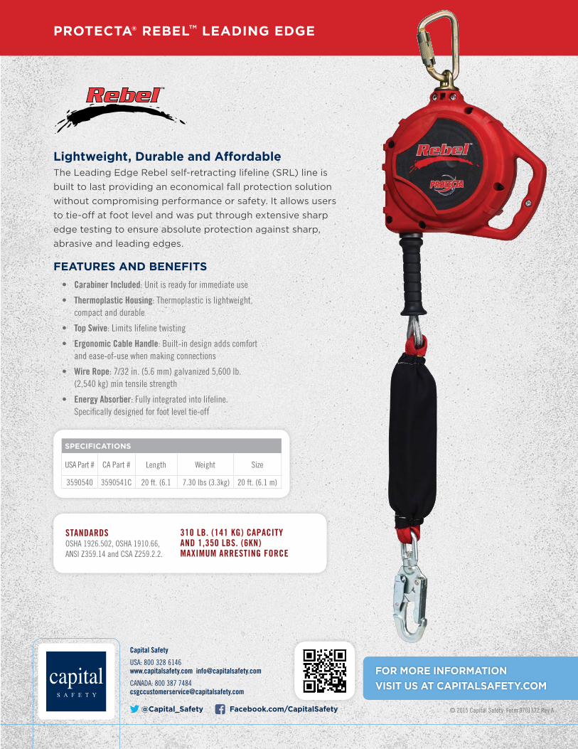
PROTECTA® REBEL™ LEADING EDGE
Capital Safety
USA: 800 328 6146 www.capitalsafety.com [email protected]
CANADA: 800 387 [email protected]
@Capital_Safety Facebook.com/CapitalSafety © 2015 Capital Safety Form 9701372 Rev A
FOR MORE INFORMATION VISIT US AT CAPITALSAFETY.COM
STANDARDSOSHA 1926.502, OSHA 1910.66, ANSI Z359.14 and CSA Z259.2.2.
310 LB. (141 KG) CAPACITY AND 1,350 LBS. (6KN) MAXIMUM ARRESTING FORCE
Lightweight, Durable and Affordable The Leading Edge Rebel self-retracting lifeline (SRL) line is built to last providing an economical fall protection solution without compromising performance or safety. It allows usersto tie-off at foot level and was put through extensive sharp edge testing to ensure absolute protection against sharp, abrasive and leading edges.
FEATURES AND BENEFITS• Carabiner Included: Unit is ready for immediate use
• Thermoplastic Housing: Thermoplastic is lightweight, compact and durable
• Top Swive: Limits lifeline twisting
• Ergonomic Cable Handle: Built-in design adds comfort and ease-of-use when making connections
• Wire Rope: 7/32 in. (5.6 mm) galvanized 5,600 lb. (2,540 kg) min tensile strength
• Energy Absorber: Fully integrated into lifeline. Specifically designed for foot level tie-off
SPECIFICATIONS
USA Part # CA Part # Length Weight Size
3590540 3590541C 20 ft. (6.1 7.30 lbs (3.3kg) 20 ft. (6.1 m)