the engineering needed for particle...
TRANSCRIPT
Phil. Trans. R. Soc. A (2012) 370, 3887–3923doi:10.1098/rsta.2011.0053
REVIEW
The engineering needed for particle physicsBY STEVE MYERS*
CERN, 1211 Geneva 23, Switzerland
Today’s particle accelerators and detectors are among the most complicated andexpensive scientific instruments ever built, and they exploit almost every aspect of today’scutting-edge engineering technologies. In many cases, accelerator needs have been thedriving force behind these new technologies, necessity being the mother of invention.This paper gives an overview of some engineering requirements for the construction andoperation of present-day accelerators and detectors.
Keywords: engineering; Large Hadron Collider; accelerator physics
1. Particle accelerators
Rutherford was the ‘godfather’ of accelerators; he challenged future generationsof accelerator builders to invent reliable machines that could accelerate particlesto higher and higher energies. In his inaugural presidential address to the RoyalSociety in London in 1928, he said ‘I have long hoped for a source of positiveparticles more energetic than those emitted from natural radioactive substances’.This was the start of a long quest for the production of high-energy beams ofparticles in a very controlled way.
Particle accelerators are also used in many different applications, such asmaterial analysis and modification, and spectrometry, especially in environmentalscience. About half of the world’s 15 000 accelerators are used as ion implanters,for surface modification, sterilization and polymerization. The ionization arisingwhen charged particles are stopped in matter is often used, for example, inradiation surgery and therapy of cancer. At hospitals, about 5000 electronaccelerators are used for this purpose. Accelerators also produce radioactiveelements that are used as tracers in medicine, biology and material science. Inmaterial science, ion and electron accelerators are used to produce neutrons andphotons over a wide range of energies. Well-defined beams of photons are, forexample, increasingly used for lithography in order to fabricate the very smallstructures required in electronics.
In this paper, an overview is given of some of the engineering requirementsfor construction and operation of modern-day accelerators. The subject is so
One contribution of 16 to a Discussion Meeting Issue ‘Ultra-precision engineering: from physics tomanufacturing’.
This journal is © 2012 The Royal Society3887
on July 19, 2018http://rsta.royalsocietypublishing.org/Downloaded from

3888 S. Myers
1017 eV
1016 eV
1015 eV
100 TeV
10 TeV
1 TeV
100 GeV
10 GeV
1 GeV
100 MeV
equi
vale
nt e
nerg
y of
a f
ixed
-tar
get a
ccel
erat
or (
E2 cm
/2M
p)
10 MeV
1 MeV
100 keV1930
academic 11 3/6/98 slide 2
1940 1950 1960 1970 1980
rectifier generator
electrostatic generator
sector focusedcyclotron
proton linacsynchrocyclotrons
electron linacsCornell
SLED
FNAL/SPSPETRA (e+/–)
LEP/SLC
HERA(ep)
Sppbar S
TeV
storage rings
ISR
AG
AG
proton synchrotronweak focusing
electronsynchrotronweak focusing
betatron
cyclotron
LHC
1990 2000
Figure 1. The history of accelerators. (Online version in colour.)
enormous that it is not possible in the limited space to go into any kind ofdetail. For this reason, references to books and papers [1–36] are given forfurther reading.
2. History
Particle accelerators and detectors have existed and been developed for morethan 80 years. During this time, many different types of accelerators have beenbuilt and operated, and the equivalent maximum energy available in the collisionshas increased by 12 orders of magnitude from 100 keV to 1017 eV (figure 1). Thisenormous energy increase has been brought about by increases in the energy of theprimary beams and the use of colliders that use collisions of beams as opposed tocolliding a primary beam with a fixed target. The sustained exponential increaseof the beam energy for the past 80 years has been achieved through repeatedjumps from saturated technologies to emerging technologies. The acceleratorsand detectors have increased enormously in complexity, size and, of course,cost. In recent years, the type of accelerator/collider most commonly (almostexclusively) used for particle physics is the synchrotron. In CERN (Geneva), there
Phil. Trans. R. Soc. A (2012)
on July 19, 2018http://rsta.royalsocietypublishing.org/Downloaded from
Review. Engineering for particle physics 3889
CMS
SPSp1976 (7km)
LHCNorth Area
ALICETT40
AD1999 (182m)
1972 (157m)
1989
BOOSTER
ISOLDE
1959 (628m)
PS
TT10
TT60
East Area
CTF3e–
TT2
p
LINAC 2
LINAC 3ions
LEIR2005 (78m)
2001
p
p
T12
TT41
neutrinos
neutrons
neutrons p (antiproton) proton/antiproton conversion neutrinos electronionp (proton)
LHC Large Hadron Collider SPS Super Proton Synchrotron
AD Antiproton Decelerator CTF3 Clic Test Facility
LEIR Low Energy Ion Ring LINAC Linear Accelerator n-ToF neutrons Time of Flight
CNGS CERN Neutrinos to Gran Sasso ISOLDE Isotope Separator Online Device
PS Proton Synchrotron
n-ToF
CNGSGran Sasso2006
LHCb
T18ATLAS
2008 (27km)
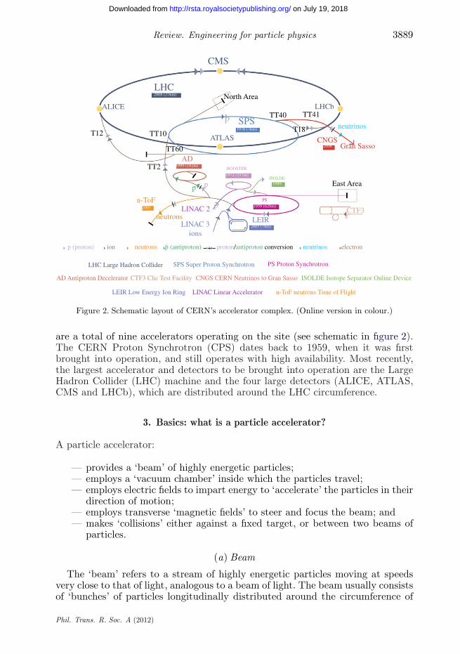
Figure 2. Schematic layout of CERN’s accelerator complex. (Online version in colour.)
are a total of nine accelerators operating on the site (see schematic in figure 2).The CERN Proton Synchrotron (CPS) dates back to 1959, when it was firstbrought into operation, and still operates with high availability. Most recently,the largest accelerator and detectors to be brought into operation are the LargeHadron Collider (LHC) machine and the four large detectors (ALICE, ATLAS,CMS and LHCb), which are distributed around the LHC circumference.
3. Basics: what is a particle accelerator?
A particle accelerator:
— provides a ‘beam’ of highly energetic particles;— employs a ‘vacuum chamber’ inside which the particles travel;— employs electric fields to impart energy to ‘accelerate’ the particles in their
direction of motion;— employs transverse ‘magnetic fields’ to steer and focus the beam; and— makes ‘collisions’ either against a fixed target, or between two beams of
particles.
(a) Beam
The ‘beam’ refers to a stream of highly energetic particles moving at speedsvery close to that of light, analogous to a beam of light. The beam usually consistsof ‘bunches’ of particles longitudinally distributed around the circumference of
Phil. Trans. R. Soc. A (2012)
on July 19, 2018http://rsta.royalsocietypublishing.org/Downloaded from

3890 S. Myers
Figure 3. LHC beam pipe with vacuum pumping slots. (Online version in colour.)
the accelerator. The bunching results from the acceleration (radio-frequency,RF) process, which uses high-frequency cavities that resonate at a harmonicof the revolution frequency of the particles (described later). For high-energyaccelerators, the typical properties of the beams are:
— a ‘bunch’ length of a few centimetres (measured in the direction of motionof the particles);
— cross-sectional size of bunches below the millimetre scale (horizontally andvertically at right angles to the direction of motion) and much smaller inthe interaction regions of the detectors;
— around 1011 charged particles per bunch;— 3000 bunches per beam (LHC); and— ultra-relativistic particle velocity; at 7 TeV (LHC) the particles are
travelling at 0.999 999 991 times the speed of light.
(b) Vacuum chamber
This is a metal pipe (also known as the beam pipe) inside which the beam ofparticles travels (figure 3). It is kept at an ultra-high vacuum (pressures less than10−10 Torr (approx. 10−10 mbar; approx. 10−8 Pa) to minimize the amount of gaspresent to avoid collisions between gas molecules and the particles in the beam.
(c) Acceleration system
High-frequency longitudinal electric fields are generated in resonant cavitystructures. These fields provide incremental acceleration to the beam of particleseach time it passes the accelerating gap of the cavity (figure 4), once per revolutionof the accelerator circumference. The acceleration becomes cumulative when thefrequency of the accelerating electric field (E) is synchronous with a harmonicof the revolution frequency of the beam. RF cavities are located intermittentlyalong the beam pipe. Each time a beam passes the cavity gap, some of the energyfrom the radio wave is transferred to the particles.
Phil. Trans. R. Soc. A (2012)
on July 19, 2018http://rsta.royalsocietypublishing.org/Downloaded from
Review. Engineering for particle physics 3891
E
beam .
.
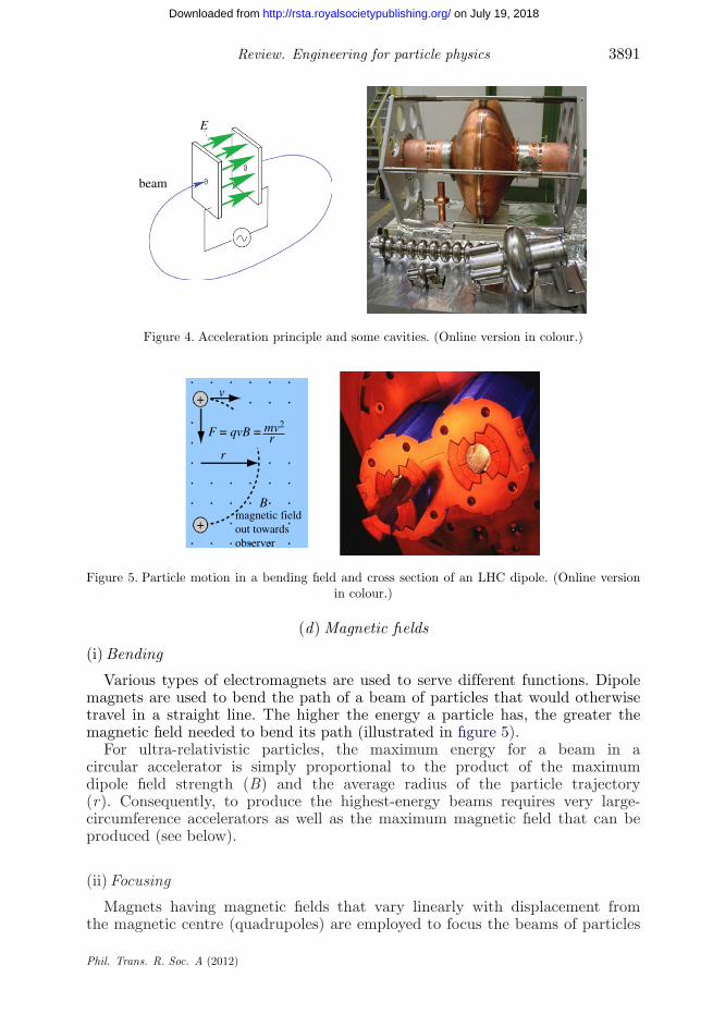
Figure 4. Acceleration principle and some cavities. (Online version in colour.)
magnetic fieldout towardsobserver
B
+
+ v
r
F = qvB = mv2
r
Figure 5. Particle motion in a bending field and cross section of an LHC dipole. (Online versionin colour.)
(d) Magnetic fields
(i) Bending
Various types of electromagnets are used to serve different functions. Dipolemagnets are used to bend the path of a beam of particles that would otherwisetravel in a straight line. The higher the energy a particle has, the greater themagnetic field needed to bend its path (illustrated in figure 5).
For ultra-relativistic particles, the maximum energy for a beam in acircular accelerator is simply proportional to the product of the maximumdipole field strength (B) and the average radius of the particle trajectory(r). Consequently, to produce the highest-energy beams requires very large-circumference accelerators as well as the maximum magnetic field that can beproduced (see below).
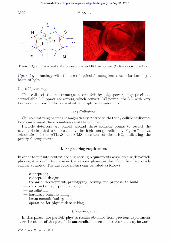
(ii) Focusing
Magnets having magnetic fields that vary linearly with displacement fromthe magnetic centre (quadrupoles) are employed to focus the beams of particles
Phil. Trans. R. Soc. A (2012)
on July 19, 2018http://rsta.royalsocietypublishing.org/Downloaded from
3892 S. Myers
.x
x
y
∂xBy=
∂By
N
NS
S
Figure 6. Quadrupolar field and cross section of an LHC quadrupole. (Online version in colour.)
(figure 6), in analogy with the use of optical focusing lenses used for focusing abeam of light.
(iii) DC powering
The coils of the electromagnets are fed by high-power, high-precision,controllable DC power converters, which convert AC power into DC with verylow residual noise in the form of either ripple or long-term drift.
(e) Collisions
Counter-rotating beams are magnetically steered so that they collide at discretelocations around the circumference of the collider.
Particle detectors are placed around these collision points to record thenew particles that are created by the high-energy collisions. Figure 7 showsschematics of the ATLAS and CMS detectors at the LHC, indicating theprincipal components.
4. Engineering requirements
In order to put into context the engineering requirements associated with particlephysics, it is useful to consider the various phases in the life cycle of a particlecollider complex. The life cycle phases can be listed as follows:
— conception;— conceptual design;— technical development, prototyping, costing and proposal to build;— construction and procurement;— installation;— hardware commissioning;— beam commissioning; and— operation for physics data-taking.
(a) Conception
In this phase, the particle physics results obtained from previous experimentssteer the choice of the particle beam conditions needed for the next step forward.
Phil. Trans. R. Soc. A (2012)
on July 19, 2018http://rsta.royalsocietypublishing.org/Downloaded from

Review. Engineering for particle physics 3893
muon detectors(a)
(b)
electromagnetic calorimeters
solenoid forward calorimetersend cap toroid
detector characteristics
AT
LA
S
width: 44 m22 m
CERN AC-ATLAS V1997
7000 tdiameter:weight:
shieldinghadronic calorimetersinner detectorbarrel toroid
magnet yoke
superconductingsolenoid magnet
hadroncalorimeter
muonchambers
one of the 15detector sectors
forward hadroncalorimeter
crystal calorimetersilicon tracker
Figure 7. Exploded diagrams of the (a) ATLAS and (b) CMS detectors. (Online version in colour.)
To a large extent, the definition of a new project in particle physics involvesspecifying the type of particles, the beam energy and the interaction rate. Duringthe past decades, the procedure followed has been to search for new results usinghadron beams, and, in the event of discovering new phenomena, to make precision
Phil. Trans. R. Soc. A (2012)
on July 19, 2018http://rsta.royalsocietypublishing.org/Downloaded from
3894 S. Myers
measurements of the new particles by using a lepton collider. The most recentexamples of this are the discovery (1984) of the W and Z particles in the SppbarS(Spp̄S) collider, followed by the precise measurement of the properties of theseparticles in the CERN Large Electron–Positron (LEP) collider (1989–2000).
The types of particle to be accelerated have a very strong influence onthe design of the machine. For high-energy circular electron–positron colliders,the important design consideration is the influence of synchrotron radiation.The particle energy lost per turn scales with the fourth power of the relativeenergy (g) of the beam (g = m/m0, where m0 is the rest mass of the particle).This lost energy must be replaced by the acceleration system. Consequently,for such high-energy circular electron–positron colliders, the RF system isthe most critical, and the most costly. One of the key parameters in thedesign of the RF system is the electrical power consumption. Consequently,the LEP room-temperature cavities were designed to have maximum shuntimpedance so as to minimize the electrical power consumption. The upgradeof LEP to higher energies (LEP2) used superconducting cavities in order tominimize the power consumption as well as to allow much higher acceleratinggradient fields.
Even with the advent of superconducting cavities, the very strong dependenceof energy lost per turn on the beam energy imposes a severe limitation on themaximum beam energy achievable in a circular lepton collider. For this reason,recent studies for future electron–positron colliders concentrate on linear colliders,in order to reduce the energy losses due to synchrotron radiation.
For protons, since the rest mass is about 2000 times that of an electron, theenergy loss per turn is much less of an issue, and consequently protons can beaccelerated to very high absolute energies. Hence, for proton colliders, in orderto increase the discovery potential, the goal is to achieve the maximum energyin collisions. As shown previously, the maximum energy depends linearly on theproduct of the bending radius of the trajectory of the tunnel and the maximumbending field strength that can be achieved. The achievable bending field in room-temperature magnets is limited by the saturation of the magnetic material toaround 2 T. Hence, for recent high-energy colliders such as the Relativistic HeavyIon Collider (RHIC), the Tevatron and the LHC, superconducting magnets havebeen developed and have allowed operational fields of 5–8.5 T.
For both hadron and lepton colliders, the interaction rate is primarilydetermined by the particle density at the collision points, i.e. the total numberof particles divided by the beam cross section. The beam size (cross section) forhadron colliders is determined by the beam coming from the injectors, whereasfor lepton colliders, the properties of the synchrotron radiation determine thebeam size. In summary, the most stringent limitations to be considered for thesemachines are the energy (and energy density) stored in the beam for hadrons(protons) and the radiated power for leptons (electrons).
(b) Conceptual design
Following the identification of the type of particles to be accelerated, therequested energy and the hoped-for event rate (luminosity), the conceptualdesign phase begins. The outcome of this phase should ensure the feasibility ofthe project, and produce a coherent set of parameters. The design should also
Phil. Trans. R. Soc. A (2012)
on July 19, 2018http://rsta.royalsocietypublishing.org/Downloaded from
Review. Engineering for particle physics 3895
1000900800700600500
400300
0 1 2 3 4 5 6 7 8 9 10 11
distance (km)
moraineSPS
plain
P4
Jura
altit
ude
(m)
molasselimestone17
0 m
P8
1.4% slope of LEP tunnel
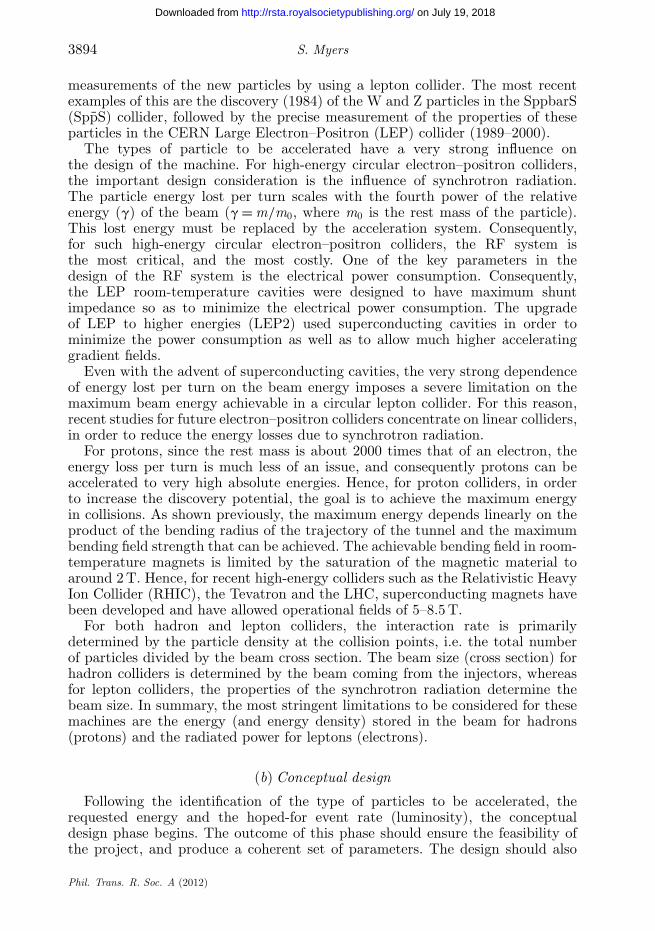
Figure 8. The inclination of the LHC tunnel. (Courtesy of J. Osborne.) (Online version in colour.)
identify some of the most critical components and initiate more detailed technicalstudies on these items. It is often necessary at this stage to identify the need fordemonstrators of the critical components. For example, in the case of the LEPcollider, demonstrators of the room-temperature RF cavities, the magnets andthe vacuum chamber were built. In order to design and build these components,extensive use of existing electro-mechanical computer codes was necessary, as wellas developing the technical expertise in the CERN workshops. The experiencegained in building these demonstrators proved invaluable for the future successof the project by identifying the most critical technical areas and allowing veryrough cost estimates.
In order to plan the civil engineering, extensive samples of the ground (rock)conditions are required in the vicinity of the proposed tunnel and the surfacebuildings. For the LEP/LHC tunnel, this analysis resulted in a repositioning ofthe tunnel, as well as inclining the plane of the tunnel (by 1.4%) so as to followthe approximate plane of the rock (figure 8). This obviated the need for extremelydeep vertical pits at the highest points of the trajectory of the tunnel. In addition,these results reduce the risk as seen by the civil engineering contractors andtherefore produce lower bids.
In order to answer some of the more fundamental beam dynamics questions,machine studies are often performed on existing accelerator facilities.
The conceptual design report should identify the most high-risk technicalcomponents, as well as giving a first indication of the possible capital cost, runningcosts and electrical power consumption.
(c) Technical development, prototyping, costing and proposal to build
Following the conceptual design phase, the detailed technical developmentbegins. This work involves first of all refining the technical details of all majorsystems, including civil engineering, survey and geodesy, magnets, accelerationsystem, beam instrumentation, vacuum system, cryogenic system, power supplies,injection and extraction systems, and collimators. By definition, this impliesexpertise in many branches of engineering and technology. For the most criticalcomponents, demonstrators and prototypes often need to be built to confirm andendorse their design and performance. For components that are needed in large
Phil. Trans. R. Soc. A (2012)
on July 19, 2018http://rsta.royalsocietypublishing.org/Downloaded from

3896 S. Myers
numbers, engineering industrialization is a key process to reduce the total cost.Some issues are specific to accelerator design:
— the precision of the circumference of the accelerator tunnel;— configuration management to allow installation in the confined area of the
tunnel;— the impact of ionizing radiation on electronic components; and— the mechanical properties of materials when subjected to impacts by high-
energy beams.
At this stage, it is of the utmost importance to take into account the multipleinterdependences of systems on other systems. In addition, owing to the factthat a beam will only continue to circulate when every single component reactscorrectly within very tight tolerances, the mean time between failures must beminimized for the systems. Sometimes this implies additional redundancy, withconcomitant cost increase.
The quality of the work done at this phase has a crucial impact on theauthorization or rejection of the project and the ultimate performance of themachine.
(d) Construction and procurement
Following the project approval, the procurement and construction follow,controlled by the project management.
Figure 9 shows the implementation of the LEP/LHC tunnel; the detailedcivil engineering numbers are given in table 1. Tunnelling was done by boringmachines, which were guided by the alignment/geodesy experts. The final resultwas that the 27 km tunnel circumference was accurate to 2 cm, as later measuredby the beam itself.
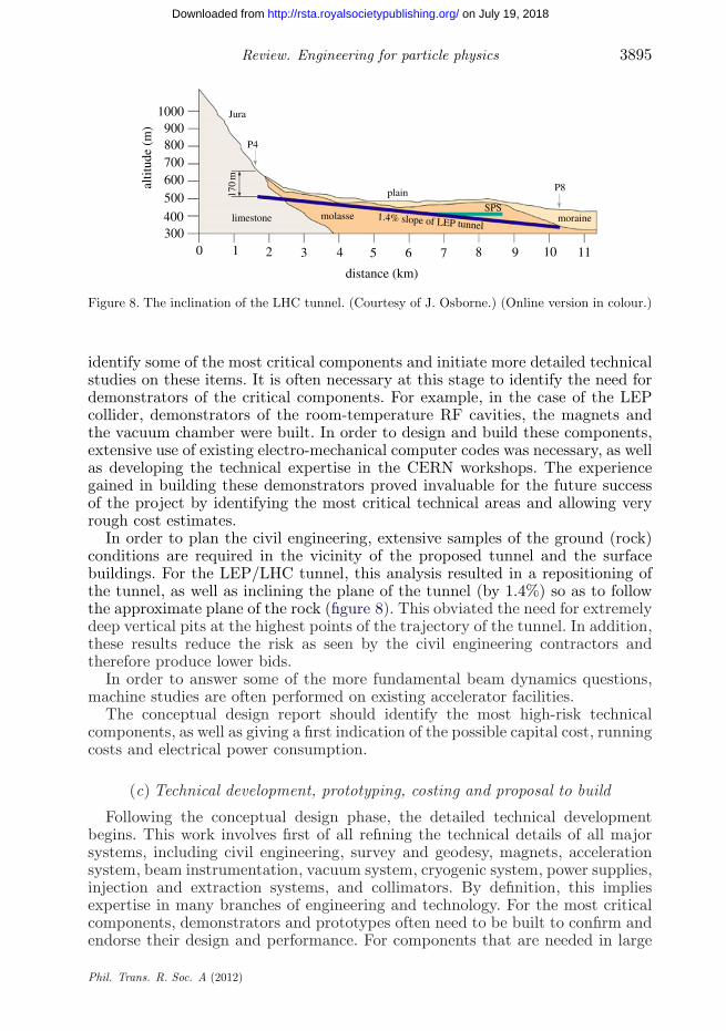
Figure 10 shows a typical example engineering drawing and a final photographof the CMS tunnel at point 5.
Calls for tender are issued to European companies for all the major systems.Contracts are given to the lowest bidders that have the technical capabilitiesto complete the work within the given time scale. During construction, CERNengineers regularly visit the factories to ensure the quality of the products andto transfer technical expertise. This technology transfer is highly appreciatedby the contracting companies. Careful budget control is exercised throughoutthis process, which finishes with the reception and technical acceptance of thefinal products.
(e) Installation
The installation of an accelerator involves a wide range of disciplines,particularly project planning, integration, heavy handling, transport, alignment,survey, mechanical engineering, electrical engineering, cryogenics, vacuum,quality assurance, safety, etc. Owing to the restricted space in the tunnel andthe high level of coactivity, very precise and rigorous planning is essential. Safetyis also an extremely important issue at this stage owing to many hazards existingsimultaneously, e.g. transport of heavy objects, pressurized vessels, high voltageand oxygen deficiency.
Phil. Trans. R. Soc. A (2012)
on July 19, 2018http://rsta.royalsocietypublishing.org/Downloaded from

Review. Engineering for particle physics 3897
(a)
(b)
point 4
point 3.3
CMS
point 5
point 6
point 7
point 8
point 3.2
point 2
point 1.8 point 1SPS
ALICE
ATLAS
point 3.3
point 3.2
point 1
point 2
point 1.8
point 4
point 5
N
point 6
point 7
point 8
LHC project buildingsexisting buildings
N
existing structuresLHC-bLHC project structures
Figure 9. Civil engineering implementation of the LEP/LHC tunnel, showing (a) undergroundworks and (b) surface buildings of LHC project. (Courtesy of J. Osborne.) (Online versionin colour.)
(f ) Cool down and hardware commissioning
Following the installation of all of the accelerator equipment, the cool downbegins. Owing to the large dimensional contractions with temperature (approx.
Phil. Trans. R. Soc. A (2012)
on July 19, 2018http://rsta.royalsocietypublishing.org/Downloaded from
3898 S. Myers
58 m
35 m
PM54
up to 55 m of moraine overburden
PX56
UXC
UP55
UP554
USC
20 m minimum rock cover
Figure 10. CMS Cavern (courtesy of J. Osborne). (Online version in colour.)
Table 1. Civil engineering numbers for the LHC tunnel project. Note that the LHC numbers arein addition to those needed for LEP.
LEP LHC
number of shafts 19 6number of underground caverns 37 32tunnel lengths, all diameters (km) 32.6 6.5number of buildings 70 30surface area of buildings (103 m2) 59 28excavated volumes (103 m3) 1100 420volume of concrete underground (103 m3) 230 125volume of concrete on surface (103 m3) 85 42
80 m in total for the LHC ring), cool down can provoke continuity problems withelectrical, vacuum, cryogenics and beam connections. All possible measurementsare made during the cool down phase. Nevertheless, some non-conformities maybe provoked that are not evident from the measurements or simply cannot bemeasured during this phase. When the machine is cold (1.9 K), the hardwarecommissioning begins. This is a preparatory phase, which is essential before beamcommissioning is started. It is crucial to test in a very comprehensive way allsystems that can be tested without the beam. All systems are put through theiroperational cycle to ensure that they behave in the specified way and with thecorrect time constants. Electrical quality assurance is critical for the magnets andthe power converters, and all other systems are carefully monitored and tested(RF, vacuum, cryogenics, etc.).
The overall system is tested with dry runs, which use the control systems,synchronization system and the applications software.
(g) Beam commissioning
The ultimate test for the hardware installed in an accelerator is the circulationof a particle beam. There are systems that need the beam before they canbe commissioned (e.g. beam instrumentation), and there are possible polarity
Phil. Trans. R. Soc. A (2012)
on July 19, 2018http://rsta.royalsocietypublishing.org/Downloaded from

Review. Engineering for particle physics 3899
inversions for any single element, of which there are tens of thousands. In addition,it is crucial that the connections to the equipment locations in the ring are correct;errors can arise due to naming conventions, the problem of having two beamstravelling in opposite directions, colour codes, etc. (For example, is longitudinalleft as seen from the inside of the ring? Is transverse left as seen for beam 1 or2?) Initial beam commissioning (examples are specific to the LHC) involves:
— beam extraction from the injector (Super Proton Synchrotron, SPS), beamtransfer through the injection beam line (3 km long, filled with acceleratorequipment) and injection into the LHC;
— ‘threading’ the injected beam (octant by octant) through the 27 km of theLHC. This is done by applications software that measures and correctsthe beam trajectory on successive injections. When the beam has passedthrough the whole circumference, it is a joyous occasion, as this is one ofthe first indications that the whole ensemble of millions of components isbehaving properly (‘the beam does not lie’);
— following the successful completion of one turn, the closed orbit is ‘closed’and the beam may circulate for tens or even hundreds of turns. This isanother joyous occasion, as this indicates that there are neither seriousobstructions in the beam pipe aperture nor any polarity errors;
— with many turns, some rudimentary measurements of the beam parameterscan be made, but at this stage, ‘capture’ of the beam by the RF systemallows the beam to circulate for very long times (hours); and
— with captured circulating beam, one starts testing the applicationssoftware, and the rest of the beam instrumentation.
(h) Operation for physics
The operational mode of an accelerator is by definition one of the most excitingand challenging. In this mode, all the subsystems and components must becontrolled in perfect harmony so that the beam can be injected, accumulated,accelerated and brought into collision. The system’s ‘glue’, which holds theoperations together, is the applications software, which makes extensive use ofthe control systems, synchronization and timing systems, as well as the localdedicated (‘hardware’) controls for each of the major components. Beams willonly survive the energy ramp if all systems are ‘ramped’ in perfect synchronism.All magnetic fields must be ramped in harmony so that the ‘optics’ seen bythe beam remains under control. The RF system must be in synchronismwith the magnetic field increase, otherwise an energy mismatch occurs. Second-order corrections are carried out by dedicated feedback systems, which measuresmall deviations from the required conditions and apply corrections. Thesesystems are, of course, totally dependent on the beam instrumentation systemproviding reliable data throughout the ramp. In addition, all safety systemsmust be fully validated, since the ‘ramp’ produces significant increases inthe stored energy of the beam as well as the magnetic stored energy. Thedetails of this mode of operation could only be covered in many hours ofintensive lectures and involve understanding of nonlinear beam dynamics aswell as knowledge of the accelerator system and the individual components inthe system.
Phil. Trans. R. Soc. A (2012)
on July 19, 2018http://rsta.royalsocietypublishing.org/Downloaded from
3900 S. Myers
5. System-by-system description of uses in accelerators
Owing to the enormous complexity in such a large number of high-technologysystems, it is impossible here to give detailed technical descriptions ordetails. On each of the subjects presented here, there are yearly specializedconferences involving hundreds of people, e.g. magnets, vacuum, accelerators,power converter, cryogenics, etc.
(a) Survey, geodesy
Particle accelerators impose very tight tolerances in absolute and relativeaccuracy for the positioning of their installed components. These tolerances resultfrom beam dynamics and mechanical (geometrical) issues, both of which influencethe aperture available for the circulating beam. The task of the surveyors is tomeasure and align the position, orientation, shape and size of all major acceleratorcomponents as well as the particle detectors to accuracies not needed in any otherdomain. In order to position a component, a reference system (frame) must bedefined. A coordinate system that defines the position of the object is attachedto this frame. The reference system at CERN has evolved with the increase ofthe size of its installations. Initially, the smaller dimensions allowed the surfaceof the Earth to be considered as a plane without introducing significant errors.
However, with the advent of the much larger accelerators of the 1970s, thesurface of the Earth could no longer be considered as a plane. A new referencesurface was adopted using a sphere and the average sea level throughout thecontinents. A new coordinate H , the altitude, was defined as the distancemeasured with respect to this surface.
As the circumference of the accelerators increased to the size of LEP (27 km),it was necessary to consider an ellipsoid of revolution as reference surface of theEarth. In addition, account had to be taken of the gravitational effects of thenearby Jura Mountains and Lake Geneva. An equipotential surface of gravity,called the geoid, to which the force of gravity is perpendicular everywhere, hasbeen defined by means of zenithal camera and gravimetric measurements. Themeasurements taken with survey instruments are therefore linked to this geoid.
Presently, the CERN reference system is a local ellipsoid that fits the Earthin the CERN area. The deviation of vertical between this ellipsoid and the local‘plumb line’ vertical has been calculated and taken into account in the new geoid.
(i) Geodetic network
The absolute positioning of accelerator components, known in an XYZcoordinate system, is ensured by means of a geodetic network. The first levelof this geodetic network is a surface network that comprises monuments solidlyanchored to the Earth, forming a very well-defined basic framework from whichthe links to national and international reference systems can be established. Thedetermination of the coordinates of these monuments is done by very accuratetriangulation, trilateration, levelling measurements and more recently by GlobalPositioning System (GPS) measurements. The accuracy of these network pointshas to be in the range of one millimetre.
This surface network, once measured, is transferred to the undergroundnetwork of the accelerator.
Phil. Trans. R. Soc. A (2012)
on July 19, 2018http://rsta.royalsocietypublishing.org/Downloaded from
Review. Engineering for particle physics 3901
0
20
40
60
80
100
120
140
160
180
1960 1965 1970 1975 1980 1985 1990 1995 2000 2005year
pow
er (
kW a
t 4.5
K)
OMEGA, BEBCISR Low-Beta
ALEPH, DELPHI,LEP Low-Beta
LEP2
LHCATLAS, CMS
LEP2+
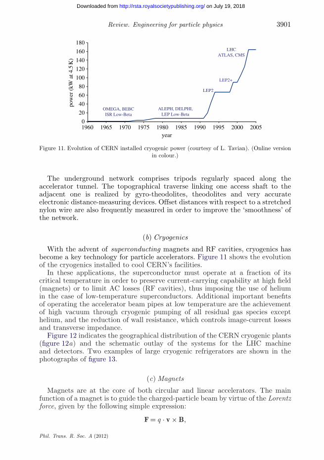
Figure 11. Evolution of CERN installed cryogenic power (courtesy of L. Tavian). (Online versionin colour.)
The underground network comprises tripods regularly spaced along theaccelerator tunnel. The topographical traverse linking one access shaft to theadjacent one is realized by gyro-theodolites, theodolites and very accurateelectronic distance-measuring devices. Offset distances with respect to a stretchednylon wire are also frequently measured in order to improve the ‘smoothness’ ofthe network.
(b) Cryogenics
With the advent of superconducting magnets and RF cavities, cryogenics hasbecome a key technology for particle accelerators. Figure 11 shows the evolutionof the cryogenics installed to cool CERN’s facilities.
In these applications, the superconductor must operate at a fraction of itscritical temperature in order to preserve current-carrying capability at high field(magnets) or to limit AC losses (RF cavities), thus imposing the use of heliumin the case of low-temperature superconductors. Additional important benefitsof operating the accelerator beam pipes at low temperature are the achievementof high vacuum through cryogenic pumping of all residual gas species excepthelium, and the reduction of wall resistance, which controls image-current lossesand transverse impedance.
Figure 12 indicates the geographical distribution of the CERN cryogenic plants(figure 12a) and the schematic outlay of the systems for the LHC machineand detectors. Two examples of large cryogenic refrigerators are shown in thephotographs of figure 13.
(c) Magnets
Magnets are at the core of both circular and linear accelerators. The mainfunction of a magnet is to guide the charged-particle beam by virtue of the Lorentzforce, given by the following simple expression:
F = q · v × B,
Phil. Trans. R. Soc. A (2012)
on July 19, 2018http://rsta.royalsocietypublishing.org/Downloaded from

3902 S. Myers
P4
8×18 kW at 4.5 K1800 SC magnets
24 km and 20 kW at 1.8 K37 000 t at 1.9 K
130 t He inventory
P5
P6
P7
P8
P11.8
P2
P3
cryogenic plant
Figure 12. Cryogenics footprint and schematic of plants. (Online version in colour.)
Figure 13. Large cryogenic helium refrigerators (33 kW at 50–75 K, 23 kW at 4.6–20 K; 41 g s−1
liquefaction) (courtesy of L. Tavian). (Online version in colour.)
where q is the electrical charge of the particle, v its velocity and B the magneticfield induction. The trajectory of a particle in the field hence depends on theparticle velocity and on the space distribution of the field. The simplest case isthat of a uniform magnetic field with a single component and velocity v normalto it, in which case the particle trajectory is a circle. A uniform field has thusa pure bending effect on a charged particle, and the magnet that generates it isgenerally referred to as a dipole. Equating the Lorentz force to the centripetalforce (figure 5), we obtain the following relation between the strength of the fieldB, the radius of the circumference r and the particle momentum p:
Br [T m] = 3.3356p [GeV c−1]
Z,
where Z is the charge number of the particle (in multiples of the electron charge),and the momentum is expressed in practical units of GeV c−1. The product Bris known as the magnetic rigidity and provides the link between dipole strength
Phil. Trans. R. Soc. A (2012)
on July 19, 2018http://rsta.royalsocietypublishing.org/Downloaded from

Review. Engineering for particle physics 3903
and length based on the desired momentum of a charged particle in a circularaccelerator. Note how the formula shows clearly the trade-off between the bendingmagnetic field B and the size of the machine (related to r).
Modern accelerators employ the following types of magnets for the givenapplications:
— dipoles, to bend the particles in a circular trajectory;— quadrupoles (magnetic field proportional to distance from the centre of
the magnetic axis), to focus the particle beams;— sextupoles (field proportional to the square of the distance from the
magnetic axis), to compensate the chromatic aberrations introduced bythe quadrupoles;
— octupoles (field proportional to the cube of the distance from the magneticaxis), to generate particle stability by introducing a frequency dependenceon particle amplitude (Landau damping); and
— in addition, ‘skew’ magnets that subject the particles to a ‘crossed’horizontal and vertical field, an example being the use of skew quadrupolesto reduce the coupling of particle motion between the horizontal andvertical planes.
The requirements of magnets to be operated in an accelerator are many andvaried. A list of the most important operational requirements is given below:
— physical constraints (space, transport, weight, etc.);— magnetic field strength;— ‘good field’ region (may depend on working point);— field quality at the different working conditions;— physical aperture;— power supply constraints;— cooling by water or by cryogenic system;— radiation resistance of the coils;— ability to align and re-align during complete lifetime;— high reliability; and— protection against the uncontrolled release of the magnetic stored energy.
The requirement on field quality is crucial to the successful operation withbeam. The magnetic field of any magnet may be represented by a Taylor seriesexpansion. Higher-order terms in this expansion can drive nonlinear motion of theparticles and ultimately cause beam loss. In a superconducting magnet, this isone of the most crucial requirements, and the nonlinear magnetic terms usuallydefine the ‘dynamic aperture’ of the machine. The dynamic aperture denotesthe largest transverse amplitude that particles can have and still be on stabletrajectories. Amplitudes larger than the dynamic aperture result in particlelosses. The dynamic aperture is derived by tracking ‘particles’ in a computersimulation for millions of turns in full six-dimensional phase space, with theparticles subjected to the measured higher-order field components in the magnets.As an example of the impact of nonlinearities, figure 14 shows a one-dimensionalphase space plot of particle motion close to a fifth-order nonlinear resonance.
Phil. Trans. R. Soc. A (2012)
on July 19, 2018http://rsta.royalsocietypublishing.org/Downloaded from
3904 S. Myers
2
(a) (b)
1
1 2
0
0x x
x ¢
–1
–1
–2
–2 1 20–1–2
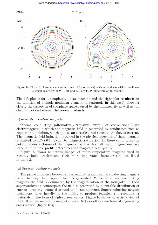
Figure 14. Plots of phase space structure near fifth order (a) without and (b) with a nonlinearelement (courtesy of W. Herr and E. Forest). (Online version in colour.)
The left plot is for a completely linear machine and the right plot results fromthe addition of a single nonlinear element (a sextupole in this case), showingclearly the distortion of the phase space caused by the nonlinearity as well as thechaotic motion between the resonant islands.
(i) Room-temperature magnets
‘Normal conducting’ (alternatively ‘resistive’, ‘warm’ or ‘conventional’) areelectromagnets in which the magnetic field is generated by conductors such ascopper or aluminium, which oppose an electrical resistance to the flow of current.The magnetic field induction provided in the physical aperture of these magnetsis limited to 1.7–2.0 T, owing to magnetic saturation. In these conditions, theyoke provides a closure of the magnetic path with small use of magneto-motiveforce, and its pole profile determines the magnetic field quality.
Figure 15 shows numerous images of room-temperature magnets used inrecently built accelerators; their more important characteristics are listedin table 2.
(ii) Superconducting magnets
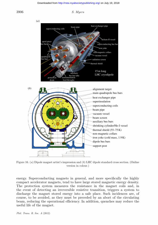
The prime difference between superconducting and normal conducting magnetsis in the way the magnetic field is generated. While in normal conductingmagnets the field is dominated by the magnetization of the iron yoke, in theirsuperconducting counterpart the field is generated by a suitable distribution ofcurrent, properly arranged around the beam aperture. Superconducting magnettechnology relies heavily on the ability to produce technical superconductingmaterials in the form of high-current cables. Figure 16 shows an artist’s view ofthe LHC superconducting magnet (figure 16a) as well as a mechanical engineeringcross section (figure 16b).
Phil. Trans. R. Soc. A (2012)
on July 19, 2018http://rsta.royalsocietypublishing.org/Downloaded from

Review. Engineering for particle physics 3905
Elettra ANKA ALBA SOLEIL
SPring-8 SLS Diamond CLS
Figure 15. Photographs of conventional magnets in many accelerator projects (courtesy of D.Tommasini). (Online version in colour.)
Table 2. Important characteristics of the conventional magnets used in many accelerator projects.
Elettra ALS ESRF ANKA ASP ALBA SOLEIL SPring-8 SLS Diamond
bending radius (m) 5.5 ∞ 23.37 5.56 ∞ 7.05 5.36 39.27 5.73 7.16number of magnets 24 36 64 16 28 32 32 88 36 48dipole field (T) 1.21 1.35 0.86 1.5 1.3 1.42 1.71 0.68 1.4 1.4gradient (T m−1) 2.86 5.19 0 0 3.35 5.65 0 0 0 0gap (mm) 70 50 54 41 42 36 37 64 41 46.6current (A) 1420 924 700? 660 695 530 538 1090 557 1337
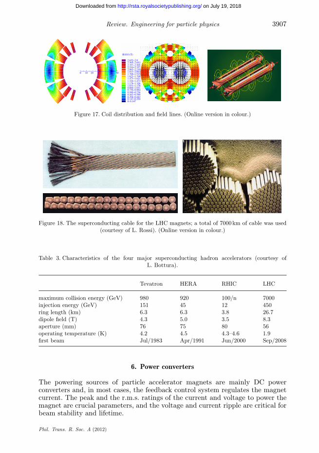
Figure 17 shows a coil cross section of the LHC dipole, the field distributionsin the ‘two-in-one’ magnet, as well as a pictorial view of the field lines.
Figure 18 shows the superconducting cable used in the LHC magnets(Rutherford cable). In total, over 7000 km of this cable was needed in theconstruction of the LHC magnets.
Superconducting magnet technology has been used in the constructionof the largest particle accelerators. Table 3 shows the main characteristicsof the four large-scale hadron accelerators built and operated usingsuperconducting magnets.
(d) Stability and margins, quench and protection
We have already remarked that an accelerator magnet superconductor mustbe operated below its critical surface. The transition of a superconductor to a‘normal’ conducting state is called a ‘quench’ and can be provoked by any suddentemperature increase caused by internal mechanical energy release or by impactby some of the particles in the high-energy beam. During the initial stages ofthe quench, the resistance of the superconducting cable increases and generatesresistive heating (i2R), resulting in thermal runaway.
In spite of taking all reasonable precautions by good design, an irreversibletransition to the normal conducting state cannot be completely excluded and themagnet must be actively protected against burn-out by its own stored magnetic
Phil. Trans. R. Soc. A (2012)
on July 19, 2018http://rsta.royalsocietypublishing.org/Downloaded from
3906 S. Myers
alignment target
thermal shield
15 m longLHC cryodipole
radiation screen
vacuum vessel
non-magnetic collars
iron yoke
superconducting bus bar
helium-II vessel
heat exchanger pipebeam pipesuperconducting coils
spool piecebus bars
bus bars
protectiondiode
instrumentationfeed throughs
auxiliarybus bar tube
quadrupole
main quadrupole bus bars
heat exchanger pipesuperinsulation
superconducting coils
beam pipe
vacuum vesselbeam screenauxiliary bus bars
shrinking cylinder/He-I vessel
thermal shield (55–75 K)non-magnetic collarsiron yoke (cold mass, 1.9 K)dipole bus bars
support post
(a)
(b)
Figure 16. (a) Dipole magnet artist’s impression and (b) LHC dipole standard cross section. (Onlineversion in colour.)
energy. Superconducting magnets in general, and more specifically the highlycompact accelerator magnets, tend to have large stored magnetic energy density.The protection system measures the resistance in the magnet coils and, inthe event of detecting an irreversible resistive transition, triggers a system todischarge the magnet stored energy into a safe place. Such incidences are, ofcourse, to be avoided, as they must be preceded by an abort of the circulatingbeam, reducing the operational efficiency. In addition, quenches may reduce theuseful life of the magnet.
Phil. Trans. R. Soc. A (2012)
on July 19, 2018http://rsta.royalsocietypublishing.org/Downloaded from
Review. Engineering for particle physics 3907
2.652–2.8
|B101| (T)
0 10 20 60
2.505–2.6522.357–2.5052.210–2.3572.063–2.2101.915–2.0631.768–1.9151.621–1.7681.473–1.6211.326–1.4731.178–1.3261.031–1.1780.884–1.0310.736–0.8840.589–0.7360.442–0.5890.294–0.4420.147–0.2940–0.147
Figure 17. Coil distribution and field lines. (Online version in colour.)
Figure 18. The superconducting cable for the LHC magnets; a total of 7000 km of cable was used(courtesy of L. Rossi). (Online version in colour.)
Table 3. Characteristics of the four major superconducting hadron accelerators (courtesy ofL. Bottura).
Tevatron HERA RHIC LHC
maximum collision energy (GeV) 980 920 100/n 7000injection energy (GeV) 151 45 12 450ring length (km) 6.3 6.3 3.8 26.7dipole field (T) 4.3 5.0 3.5 8.3aperture (mm) 76 75 80 56operating temperature (K) 4.2 4.5 4.3–4.6 1.9first beam Jul/1983 Apr/1991 Jun/2000 Sep/2008
6. Power converters
The powering sources of particle accelerator magnets are mainly DC powerconverters and, in most cases, the feedback control system regulates the magnetcurrent. The peak and the r.m.s. ratings of the current and voltage to power themagnet are crucial parameters, and the voltage and current ripple are critical forbeam stability and lifetime.
Phil. Trans. R. Soc. A (2012)
on July 19, 2018http://rsta.royalsocietypublishing.org/Downloaded from

3908 S. Myers
YD
YD
Figure 19. Six-pulse thyristor rectifier (courtesy of F. Bordry and J.-P. Burnet).
Three main families of power converter are used for particle accelerators:thyristor-controlled rectifier, switch-mode power converter and dischargedpower converter.
The thyristor-controlled rectifier was the main type used from the 1970sup to the 1990s. Many different configurations are implemented with thyristordevices; the simplest one is the six-pulse thyristor rectifier with freewheeling diode(figure 19).
(a) Switch-mode power converter with high-frequency transformer
One of the main interests in using the switch-mode power converter with ahigh-frequency transformer is to reduce the volume of the power converters.Ferrite cores are widely produced and available at a competitive price. A classicaltopology is shown in figure 20.
In the case of the CERN LHC, where the power converters must be installedunderground with limited space, the switch-mode power converter was chosenfor power converter up to 200 kW. In this case, many sub-converters are placedin parallel to reach the required power level. The superconducting magnetsrequire high current (many kiloamps) and low voltage (less than 20 V); for thisapplication, the solution is to drive many high-frequency transformers in serieswith one inverter.
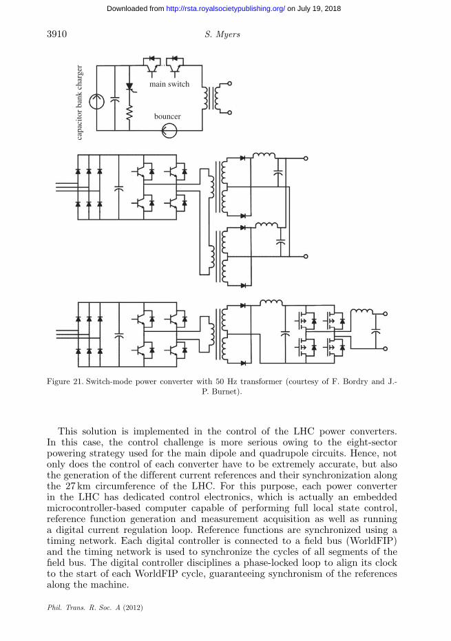
(b) Switch-mode power converter with 50 Hz transformer
If the volume of the power converter is not an issue, 50 Hz transformers canbe used, as they are produced by industry for other applications at affordableprices. The most classical topology used for particle accelerators can be seen in
Phil. Trans. R. Soc. A (2012)
on July 19, 2018http://rsta.royalsocietypublishing.org/Downloaded from

Review. Engineering for particle physics 3909
YY
Y Y
+
–
D
D D
Figure 20. Switch-mode power converter with high-frequency transformer (courtesy of F. Bordryand J.-P. Burnet).
figure 21. For power converters above 10 kW, the classical switching frequency isin the range of 1–20 kHz.
(c) High accuracy in power converters for particle accelerators
The power converters that drive the magnets in particle accelerators can beconsidered as controlled current sources with current feedback based on referencevalues as a function of time.
The accuracy of the feedback control is determined primarily by the currentmeasurement transducer and, in the case of digitally controlled power converters,the control algorithm and the analogue-to-digital converter (ADC) employed inthe feedback loop.
(d) Digital power converter control
The advantages of digital control are numerous: increased stabilityand reproducibility, less susceptibility to noise and thermal effects, easyimplementation of different control methods as well as easy loop parametrization.On the negative side, the use of digital control increases system complexity andintroduces new sources of error such as those related to ADC measurement.
When maximum accuracy is required, the most effective present strategy is tocontrol the power supply voltage source by the output current of the converter.In this case, the output current of the converter is read by an ADC connectedto a current transducer and then compared with a digital reference. The error isfed into a digital regulator and the result sent to a digital-to-analogue converter(DAC) that provides an analogue signal to control the voltage source.
Phil. Trans. R. Soc. A (2012)
on July 19, 2018http://rsta.royalsocietypublishing.org/Downloaded from
3910 S. Myers
main switch
bouncer
capa
cito
r ba
nk c
harg
er
Figure 21. Switch-mode power converter with 50 Hz transformer (courtesy of F. Bordry and J.-P. Burnet).
This solution is implemented in the control of the LHC power converters.In this case, the control challenge is more serious owing to the eight-sectorpowering strategy used for the main dipole and quadrupole circuits. Hence, notonly does the control of each converter have to be extremely accurate, but alsothe generation of the different current references and their synchronization alongthe 27 km circumference of the LHC. For this purpose, each power converterin the LHC has dedicated control electronics, which is actually an embeddedmicrocontroller-based computer capable of performing full local state control,reference function generation and measurement acquisition as well as runninga digital current regulation loop. Reference functions are synchronized using atiming network. Each digital controller is connected to a field bus (WorldFIP)and the timing network is used to synchronize the cycles of all segments of thefield bus. The digital controller disciplines a phase-locked loop to align its clockto the start of each WorldFIP cycle, guaranteeing synchronism of the referencesalong the machine.
Phil. Trans. R. Soc. A (2012)
on July 19, 2018http://rsta.royalsocietypublishing.org/Downloaded from

Review. Engineering for particle physics 3911
(e) Current measurement in particle accelerators
The requirements for beam current measurement have driven progress intransducer technology, culminating with the invention of the direct-currentcurrent transformer (DCCT) at CERN in the late 1960s. The idea was tobuild a magnetic beam current transformer (BCT) with frequency responseextended down to DC to measure beam current in the Intersecting Storage Rings(ISR) accelerator. Although the new transducer was not initially intended forpower supply regulation applications, its advantages compared with previous DCinstrument transformers soon became obvious.
The last decade has seen important progress in DCCT technology with thedevelopment and deployment of the DCCTs for the main dipole and quadrupolepower supplies of the LHC. Short-term stability of the order of two parts permillion (ppm), yearly drifts better than 15 ppm and linearity better than 2 ppmhave been achieved.
7. Ultra-high vacuum
In particle accelerators, the beam pipes must be at ultra-high vacuum (UHV)in order to reduce the beam–gas interactions, i.e. the scattering of beamparticles resulting from collisions with the molecules of the residual gas. Theseinteractions reduce the beam lifetime (nuclear scattering) and the luminosity(multiple Coulomb scattering). They can also cause intensity limitations provokedby pressure instabilities and by electron-induced instabilities (for positivebeams only).
Beam–gas scattering can also increase the background in the detectors andthe radiation dose rates in the accelerator tunnels. The latter leads to materialactivation, increased radiation dose rates to intervention crews, prematuredegradation of tunnel infrastructure such as cables and electronics, and finallyhigher probability of electronic single event upsets (SEUs) produced by neutrons.SEUs are of great concern for the electronics in the tunnel as well as in theservice galleries.
The design of an accelerator vacuum system must observe severe additionalconstraints, which must be taken into account at the design stage. Among theseconstraints, the ‘impedance’ seen by the beam must be minimized in order topreserve beam stability, the generation of radio-frequency higher-order modes(HOMs) must be minimized so as to avoid local heating by the beam, andthe beam aperture in the magnets must be maintained sufficient to allow goodbeam lifetime.
For accelerators operating at cryogenic temperatures, the heat load induced byscattered beam particles and synchrotron radiation can also be an issue for thecryo-magnets, since local heat loads can lead to magnet quenches.
(a) Synchrotron radiation
When a particle beam traverses a perpendicular magnetic field, it radiatesphotons and loses energy by synchrotron radiation. The interaction of thephotons with the vacuum chamber wall stimulates molecular gas desorption anddissipates heat.
Phil. Trans. R. Soc. A (2012)
on July 19, 2018http://rsta.royalsocietypublishing.org/Downloaded from
3912 S. Myers
In high-energy electron accelerators (e.g. LEP, Diamond and SOLEIL), theheat load due to synchrotron radiation reaches several tens of kW m−1. Thisrequires careful engineering design to keep the beam pipe at a reasonabletemperature. In the LHC, the heat load of 0.2 W m−1 is evacuated by the beamscreen’s cooling circuit maintained between 5 and 20 K, while the cold bore isoperating at 1.9 K.
(b) Electron cloud
Operation with high-intensity, closely spaced, bunches can lead to theformation of a cloud of electrons. This effect has been seen in and posed alimitation to performance of the following machines: ISR, PSR, KEK-B, PEP-II,SPS and recently the LHC. The generated electron cloud affects the beamproperties and contributes to the vacuum dynamics. When an electron is inthe vicinity of the beam potential, it experiences the electromagnetic forcesof the beam. Photoelectrons can be produced, which ionize the residual gasand allow the multiplication of secondary electrons. In the LHC, for example,the proton bunch intensity is large enough to give a kick of approximately100 eV to the stray electrons. On interaction with the inner surface of thevacuum pipe, these electrons stimulate gas desorption and produce secondaryelectrons. The secondary electrons are further accelerated to approximately100 eV by the following bunch, 25 ns apart, leading to an avalanche in theproduction of electrons.
The secondary electron yield (SEY) is the key parameter that defines thevacuum level in a beam tube. It is defined as the ratio of the number of producedelectrons to the number of incident electrons. Typical SEY values for metallicsurfaces are approximately 2.
(c) Vacuum pumping
The pumping scheme is often decided at the early stages of the design, sinceit affects the overall engineering of the accelerator.
In particle accelerators, discrete pumping is the most commonly used solutionand is often achieved by ion pumps combined with sublimation or non-evaporablegetter (NEG) cartridge pumps, cryogenic and turbo-molecular pumps.
Ion pumps are widely used since they are very reliable and provide ahigh pumping speed. Ion pumps also have the advantage of pumping all gasspecies and, once baked-out at 250–300◦C, the ultimate pressure is in the low10−10 Pa range.
Sublimation pumps are often used to speed up the pump down to the UHVpressure range or as a complement to ion pumps at very low pressures. Similarlyto NEG pumps, the major limitation of sublimation pumps is related to thepumping speed of noble gases and methane.
8. Beam instabilities
(a) Impedance and collective effects
As the beam intensity increases, the beam can no longer be considered as acollection of non-interacting single particles; in addition to the ‘single-particle
Phil. Trans. R. Soc. A (2012)
on July 19, 2018http://rsta.royalsocietypublishing.org/Downloaded from
Review. Engineering for particle physics 3913
(a) (b)
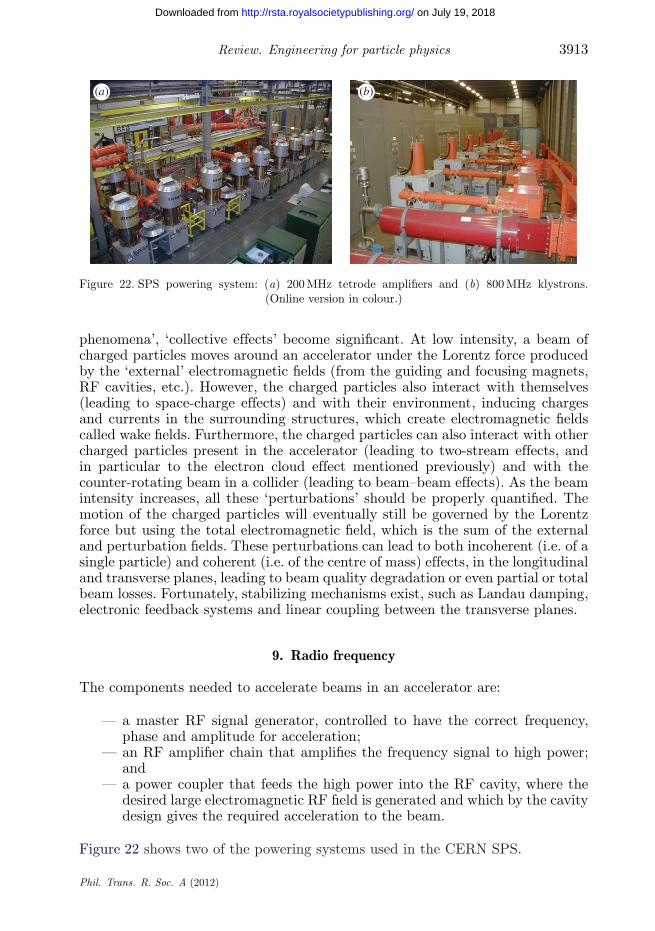
Figure 22. SPS powering system: (a) 200 MHz tetrode amplifiers and (b) 800 MHz klystrons.(Online version in colour.)
phenomena’, ‘collective effects’ become significant. At low intensity, a beam ofcharged particles moves around an accelerator under the Lorentz force producedby the ‘external’ electromagnetic fields (from the guiding and focusing magnets,RF cavities, etc.). However, the charged particles also interact with themselves(leading to space-charge effects) and with their environment, inducing chargesand currents in the surrounding structures, which create electromagnetic fieldscalled wake fields. Furthermore, the charged particles can also interact with othercharged particles present in the accelerator (leading to two-stream effects, andin particular to the electron cloud effect mentioned previously) and with thecounter-rotating beam in a collider (leading to beam–beam effects). As the beamintensity increases, all these ‘perturbations’ should be properly quantified. Themotion of the charged particles will eventually still be governed by the Lorentzforce but using the total electromagnetic field, which is the sum of the externaland perturbation fields. These perturbations can lead to both incoherent (i.e. of asingle particle) and coherent (i.e. of the centre of mass) effects, in the longitudinaland transverse planes, leading to beam quality degradation or even partial or totalbeam losses. Fortunately, stabilizing mechanisms exist, such as Landau damping,electronic feedback systems and linear coupling between the transverse planes.
9. Radio frequency
The components needed to accelerate beams in an accelerator are:
— a master RF signal generator, controlled to have the correct frequency,phase and amplitude for acceleration;
— an RF amplifier chain that amplifies the frequency signal to high power;and
— a power coupler that feeds the high power into the RF cavity, where thedesired large electromagnetic RF field is generated and which by the cavitydesign gives the required acceleration to the beam.
Figure 22 shows two of the powering systems used in the CERN SPS.
Phil. Trans. R. Soc. A (2012)
on July 19, 2018http://rsta.royalsocietypublishing.org/Downloaded from

3914 S. Myers
Figure 23. (a) Radio-frequency quadrupole (RFQ) and (b) drift-tube linac (DTL). (Online versionin colour.)
Table 4. Cavities in the PS complex.
harmonic frequency peakcavity count number range (MHz) voltage (kV)
PSB C02 1 per ring 1 0.6–1.8 8C04 1 per ring 2 1.2–3.9 8C16 1 per ring 8–24 6–17 6
PS C10 10 + 1 7–21 2.7–10 1–20C20 1 + 1 28, 42 13 or 20 15C40 1 + 1 84 40 3–350C80 2 + 1 168, 169 80 350C200 4 + 2 420–433 200 30
There are many different types of cavities for different types of accelerators.In the lower energy range where linear accelerators are used, the two commonstructures are radio-frequency quadrupoles (RFQs) and drift-tube linacs (DTLs;figure 23). The RFQ both focuses and accelerates the beam.
In lower energy synchrotrons, which cover a large energy range (typically afactor of 10–30 between injection and top energy), the cavity frequency must beincreased during acceleration so as to synchronize with the increasing revolutionfrequency of the beam. Table 4 shows the range of cavities and their parametersfor the Proton Synchrotron Booster (PSB) and the Proton Synchrotron (PS)itself. In the lower energy PSB, three different types of cavities cover a frequencyrange from 0.6 to 17 MHz. The PSB accelerates protons from 50 MeV to 1.4 GeV,which increases the proton velocity and consequently the revolution frequency byabout a factor of 3 in 500 ms. In such cases, needing variable-frequency cavities,one uses ferrite-loaded cavities with magnetic tuning. In the higher energy PS,there are two variable-frequency systems covering the range 2.7–20 MHz as wellas three fixed-frequency systems at 40, 80 and 200 MHz.
Phil. Trans. R. Soc. A (2012)
on July 19, 2018http://rsta.royalsocietypublishing.org/Downloaded from
Review. Engineering for particle physics 3915
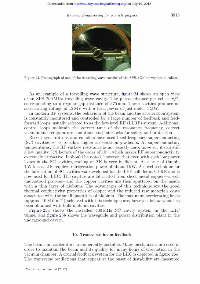
Figure 24. Photograph of one of the travelling wave cavities of the SPS. (Online version in colour.)
As an example of a travelling wave structure, figure 24 shows an open viewof an SPS 200 MHz travelling wave cavity. The phase advance per cell is p/2,corresponding to a regular gap distance of 375 mm. These cavities produce anaccelerating voltage of 12 MV with a total power of just under 4 MW.
In modern RF systems, the behaviour of the beam and the acceleration systemis constantly monitored and controlled by a large number of feedback and feed-forward loops, usually referred to as the low-level RF (LLRF) system. Additionalcontrol loops maintain the correct tune of the resonance frequency, correctvacuum and temperature conditions and interlocks for safety and protection.
Recent synchrotrons and colliders have used fixed-frequency superconducting(SC) cavities so as to allow higher acceleration gradients. At superconductingtemperatures, the RF surface resistance is not exactly zero; however, it can stillallow quality (Q) factors of the order of 1010, which makes RF superconductivityextremely attractive. It should be noted, however, that even with such low powerlosses in the SC cavities, cooling at 2 K is very inefficient. As a rule of thumb,1 W lost at 2 K requires refrigeration power of about 1 kW. A novel technique forthe fabrication of SC cavities was developed for the LEP collider at CERN and isnow used for LHC. The cavities are fabricated from sheet metal copper—a wellunderstood process—and the copper cavities are then sputtered on the insidewith a thin layer of niobium. The advantages of this technique are the goodthermal conductivity properties of copper and the reduced raw materials costsassociated with the small quantities of niobium. The maximum accelerating fields(approx. 10 MV m−1) achieved with this technique are, however, below what hasbeen obtained with bulk niobium cavities.
Figure 25a shows the installed 400 MHz SC cavity system in the LHCtunnel and figure 25b shows the waveguide and power distribution plant in theunderground cavern.
10. Transverse beam feedback
The beams in accelerators are inherently unstable. Many mechanisms are used inorder to maintain the beam and its quality for many hours of circulation in thevacuum chamber. A crucial feedback system for the LHC is depicted in figure 26a.The transverse oscillations that appear at the onset of instability are measured
Phil. Trans. R. Soc. A (2012)
on July 19, 2018http://rsta.royalsocietypublishing.org/Downloaded from
3916 S. Myers
(a) (b)
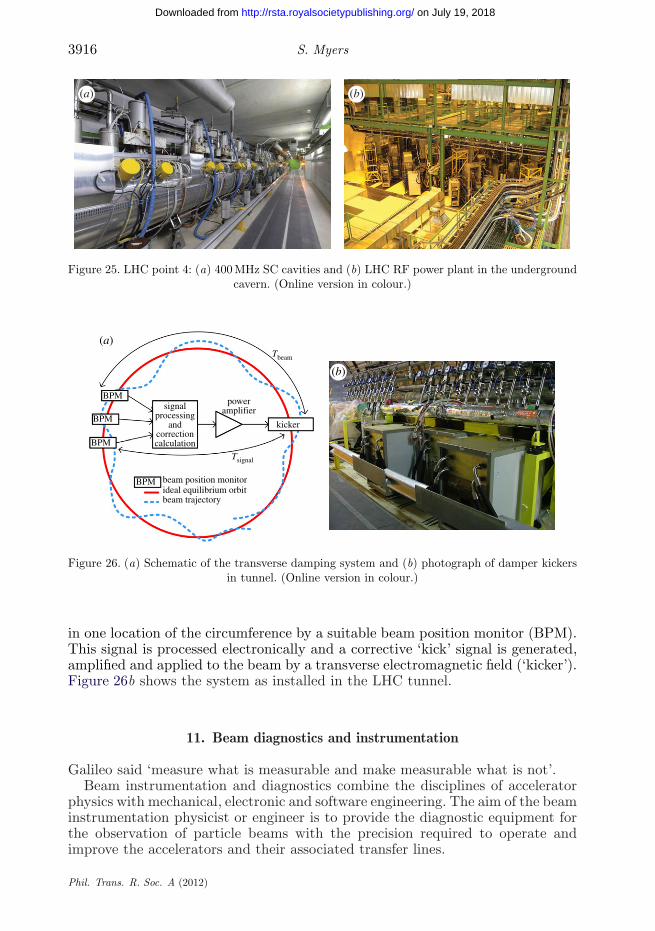
Figure 25. LHC point 4: (a) 400 MHz SC cavities and (b) LHC RF power plant in the undergroundcavern. (Online version in colour.)
BPM
BPM
BPM
signalprocessing
andcorrectioncalculation
beam position monitorBPMideal equilibrium orbitbeam trajectory
poweramplifier
kicker
Tsignal
Tbeam
(a)
(b)
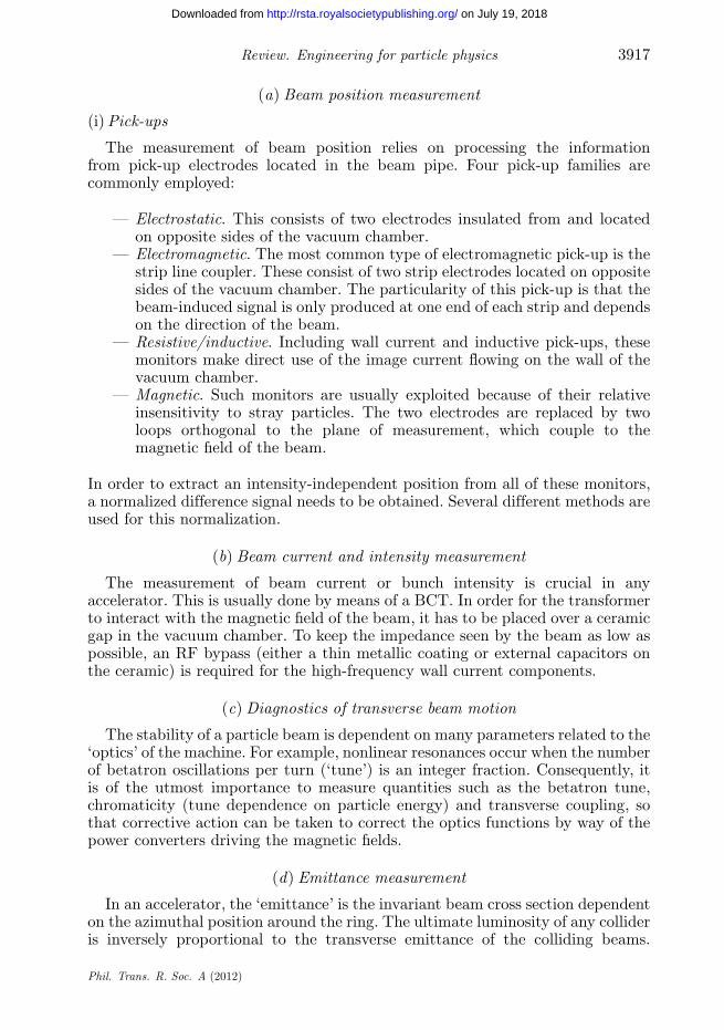
Figure 26. (a) Schematic of the transverse damping system and (b) photograph of damper kickersin tunnel. (Online version in colour.)
in one location of the circumference by a suitable beam position monitor (BPM).This signal is processed electronically and a corrective ‘kick’ signal is generated,amplified and applied to the beam by a transverse electromagnetic field (‘kicker’).Figure 26b shows the system as installed in the LHC tunnel.
11. Beam diagnostics and instrumentation
Galileo said ‘measure what is measurable and make measurable what is not’.Beam instrumentation and diagnostics combine the disciplines of accelerator
physics with mechanical, electronic and software engineering. The aim of the beaminstrumentation physicist or engineer is to provide the diagnostic equipment forthe observation of particle beams with the precision required to operate andimprove the accelerators and their associated transfer lines.
Phil. Trans. R. Soc. A (2012)
on July 19, 2018http://rsta.royalsocietypublishing.org/Downloaded from
Review. Engineering for particle physics 3917
(a) Beam position measurement
(i) Pick-ups
The measurement of beam position relies on processing the informationfrom pick-up electrodes located in the beam pipe. Four pick-up families arecommonly employed:
— Electrostatic. This consists of two electrodes insulated from and locatedon opposite sides of the vacuum chamber.
— Electromagnetic. The most common type of electromagnetic pick-up is thestrip line coupler. These consist of two strip electrodes located on oppositesides of the vacuum chamber. The particularity of this pick-up is that thebeam-induced signal is only produced at one end of each strip and dependson the direction of the beam.
— Resistive/inductive. Including wall current and inductive pick-ups, thesemonitors make direct use of the image current flowing on the wall of thevacuum chamber.
— Magnetic. Such monitors are usually exploited because of their relativeinsensitivity to stray particles. The two electrodes are replaced by twoloops orthogonal to the plane of measurement, which couple to themagnetic field of the beam.
In order to extract an intensity-independent position from all of these monitors,a normalized difference signal needs to be obtained. Several different methods areused for this normalization.
(b) Beam current and intensity measurement
The measurement of beam current or bunch intensity is crucial in anyaccelerator. This is usually done by means of a BCT. In order for the transformerto interact with the magnetic field of the beam, it has to be placed over a ceramicgap in the vacuum chamber. To keep the impedance seen by the beam as low aspossible, an RF bypass (either a thin metallic coating or external capacitors onthe ceramic) is required for the high-frequency wall current components.
(c) Diagnostics of transverse beam motion
The stability of a particle beam is dependent on many parameters related to the‘optics’ of the machine. For example, nonlinear resonances occur when the numberof betatron oscillations per turn (‘tune’) is an integer fraction. Consequently, itis of the utmost importance to measure quantities such as the betatron tune,chromaticity (tune dependence on particle energy) and transverse coupling, sothat corrective action can be taken to correct the optics functions by way of thepower converters driving the magnetic fields.
(d) Emittance measurement
In an accelerator, the ‘emittance’ is the invariant beam cross section dependenton the azimuthal position around the ring. The ultimate luminosity of any collideris inversely proportional to the transverse emittance of the colliding beams.
Phil. Trans. R. Soc. A (2012)
on July 19, 2018http://rsta.royalsocietypublishing.org/Downloaded from
3918 S. Myers
Emittance measurements are therefore of particular importance in such machines.The emittance is measured in many and varied ways.
(i) Secondary emission grids
Secondary emission (SEM) grids consist of ribbons or wires that are placed inthe beam. As the beam intercepts the grid, SEM produces a current in each stripthat is proportional to the beam intensity at that location. By measuring thiscurrent for all strips, a beam profile is obtained. SEM grids are the most widelyused means to measure the density profile of beams in transfer lines.
(ii) Scintillator and optical transition radiation screens
Scintillator screens have been used for nearly a century; the modern versionconsists of a doped alumina screen that is intercepted by the beam. In its simplestform, a graduated screen is observed using a TV camera.
Optical transition radiation (OTR) screens are a less expensive alternativeto scintillator screens. OTR radiation is generated when a charged-particle beamtransits the interface of two media with different dielectric constants (e.g. vacuumto metal or vice versa). The radiation produced is emitted in two cones andimaging can again be performed using simple optics followed by a charge-coupleddevice (CCD) camera.
(iii) Wire scanners
Wire scanners come in two different types rotating and linear. Rotating wirescanners are operated at speeds of up to 20 m s−1 and consist of a thin wire (sometens of micrometres in diameter) mounted on a fork that is attached to a rotatingmotor, while linear scanners use motors that push/pull the wire across the beam.There are two ways of obtaining a beam profile with wire scanners: by measuringthe SEM current as a function of wire position (similar to SEM grid acquisition)or by measuring the flux of secondary particles created as the beam interactswith the wire.
(iv) Residual gas and luminescence monitors
Residual gas monitors are used in many high-energy accelerators in order toreconstruct transverse beam distributions. The signal results from the collectionof either the ions or the electrons produced by the beam ionizing the small amountof residual gas in the vacuum chamber. These ions or electrons are acceleratedusing a bias voltage of several kilovolts and collected on a microchannelplate (MCP). The avalanche of electrons produced by the MCP then hits aphosphor screen, giving an image of the beam profile that can be monitoredusing a CCD camera.
(v) Synchrotron radiation monitors
Synchrotron radiation monitors are limited to highly relativistic particles andoffer a completely non-destructive and continuous measurement of the two-dimensional density distribution of the beam. These monitors make use of thelight produced when highly relativistic particles are deflected by a magnetic field.
Phil. Trans. R. Soc. A (2012)
on July 19, 2018http://rsta.royalsocietypublishing.org/Downloaded from

Review. Engineering for particle physics 3919
The most common way of measuring the beam size with synchrotronradiation is to directly image the extracted light using traditional optics anda camera.
(e) Beam loss monitoring
Beam loss monitors (BLMs) have three main uses in particle accelerators:damage prevention, diagnostics and machine optimization. The most commontype of BLM is the ionization chamber, owing to their robustness and largedynamic range. The chamber provides the medium with which the secondaryparticles created by the beam loss can interact (typically a gas such as nitrogenor argon).
The BLM systems are crucial for the detection of particles ‘lost’ from the beam.They form part of the machine protection system, which detects particle lossesabove a certain threshold and triggers a beam abort so as to avoid a quench ofthe magnets.
12. Injection and extraction techniques
Transfer of beam between accelerators or onto external dumps, targets andmeasurement devices requires injection, extraction and beam transfer lines.Injection is the final component of the transfer of beam between one acceleratorand another, either from a linear to a circular accelerator or between circularaccelerators. Extraction is the removal of beam from an accelerator, either forthe transfer to another accelerator or to a target, dump or measurement system.Injection and extraction systems need to be designed to transfer beam withminimum beam loss, to achieve the desired beam parameters and often withminimum dilution of the beam emittance.
Single-turn injection and extraction methods are rather straightforward forboth lepton and hadron machines. They generally involve a septum (or series ofsepta) to deflect the beam into or out of the accelerator aperture, a kicker todeflect the beam onto or away from the closed orbit, and a closed orbit bumpto reduce the required kick strength. For these methods, the beam losses can bevery low, and the emittance dilution associated with the injection or extractioncan be very small.
13. Injection- and extraction-related hardware: kickers and septa
Although kickers and magnetic septa are also dipole magnets following the sameprinciples as ordinary bending elements, they have very distinct features, andmust often fulfil conflicting design requirements. Kickers and septa are typicallypurpose-built single elements or only produced in small series. Many of theelements are installed under vacuum, with the resulting implications.
The rise time of kickers must be very short (ranging from several microsecondsdown to several nanoseconds), while the requirements on the reproducibility of theflat-top amplitude and the ripple are still quite stringent (at least consideringthe pulse-type excitation). Redundancy can also be a design criterion: if oneof the devices fails, those remaining should be sufficient, in combination with
Phil. Trans. R. Soc. A (2012)
on July 19, 2018http://rsta.royalsocietypublishing.org/Downloaded from

3920 S. Myers
special protection elements, to handle the beam safely. There is only one singleaction on the beam and the timing needs to be precisely set up; online correctionsare not possible. Applications are often safety critical (beam abort systems) andimminent failures must be recognized in real time.
(a) Electrostatic and magnetic septa
A septum, either electrostatic or magnetic, constitutes the separation betweenan area of ideally zero field, which is traversed by the circulating beam, froman area with high field in which the injected or extracted beam experiencesa deflection. The septum should be as thin as possible to keep the strengthrequirements for the associated kicker at a reasonable level, and to reduce particlelosses and irradiation of the septum and the surroundings. Since the beam passesonly once through the high-field area of a septum, its field homogeneity is notas critical as for normal bending magnets. However, the stray field into the‘field-free’ region must be minimized, since the circulating beam experiencesit at every passage.
(b) Electrostatic septa
Electrostatic septa can be made very thin since normally they do not carrycurrents. They consist of either a series of wires (several 100 to over 1000,made, for instance, out of tungsten–rhenium) or a set of foils (for instance, ofmolybdenum), which are precision-aligned on a support frame.
14. Collimators
Collimators are special accelerator devices that place scattering or absorbingblocks of materials around the beam. They can be fixed or movable with respectto the beam. The collimator jaws are the blocks of material that are placed closeto the beam. The jaw material is characterized by its nuclear properties, thermalconductivity, electrical resistivity, mechanical properties (surface roughness andflatness) and vacuum properties (residual outgassing rates). A collimation systemis an ensemble of collimators that is integrated into the accelerator layout tointercept stray particles and to protect the accelerator.
(a) Requirements for modern collimators
Modern collimators must support the operation of accelerators with high powerloss and beams that are often beyond the destruction limits of available materials.At the same time, collimators must be placed very close to the beam, andallowable tolerances have reached the micrometre regime. Collimators thus arecooled, high-power devices, which are highly radioactive, must be good absorbers,extremely robust and work as precision tools.
(b) High power loads
State-of-the-art accelerators have advanced into the regime of high beambrightness. This regime is characterized by a high beam power that is compressed
Phil. Trans. R. Soc. A (2012)
on July 19, 2018http://rsta.royalsocietypublishing.org/Downloaded from

Review. Engineering for particle physics 3921
1000
100
stor
ed e
nerg
y (M
J)
10
1
0.1
0.011 10
SNSPEP-II
KEKB
ISR
RHIC RHIC
SPS
SPS
LHC(2010)
LHC(2010)
LHCLHC
ILC
ILC
LEP-2 LEP-2ISR
PEP-II
KEKB
SNSCLIC
CLIC
TevatronTevatron
HERA-pHERA-p
beam momentum (GeV c–1) beam momentum (GeV c–1)100 1000 10 000
ener
gy d
ensi
ty (
MJ m
m–2
)
1 10 100 1000 10 000
1000
10 000
100
10
1
0.1
0.01
(a) (b)
Figure 27. (a) The stored energy and (b) the density of stored energy versus the beammomentum for various accelerators. Filled symbols refer to proton, while open symbols indicateelectron/positron accelerators. ILC and CLIC are design studies. (Courtesy of R. Assmann.)(Online version in colour.)
into a small transverse beam size. The beam power can be characterized byconsidering the energy that is stored in one beam with Np charged particles:
Estored = pceNp. (14.1)
Here, c is the light velocity. We consider particles with charge q = e andrelativistic momentum p. The stored energy in the beams is compared in figure 27for several accelerator facilities. It is seen that modern accelerators operate at orare designed for beam momenta between a few GeV c−1 to a few TeV c−1. Thestored beam energies are in the range 10 kJ to 500 MJ. Losses and power loadsmust be distinguished for different types of accelerators.
(c) Destructive beam densities
The transverse beam size sz at collimator locations has decreased over theyears, either due to lower normalized emittances from injectors or due to theoperation at high beam energies. This increases the energy density in the beam:
rE = Estored
psxsy. (14.2)
The stored energy densities are compared in figure 27 for several facilities; thebeam size is taken at typical collimator locations. It is noted that this parameteris directly proportional to relevant performance parameters such as luminosityand therefore is usually maximized.
The stored energy densities range from 10 kJ mm−2 to 4 GJ mm−2. Damagelimits depend on the type and length of material that is hit by the beam. Typicalvalues for metals are around 50 kJ mm−2. Very robust materials such as fibre-reinforced carbon can survive an impacting proton energy density of around5 MJ mm−2 for 1 m long blocks. In many cases, collimators can only survivefractions of the collimated beam. A full beam impact must be avoided andcollimators must be designed for maximum robustness, non-catastrophic failurein case of beam impact and in situ handling of damaged surfaces.
Phil. Trans. R. Soc. A (2012)
on July 19, 2018http://rsta.royalsocietypublishing.org/Downloaded from

3922 S. Myers
15. Accelerator systems that were not covered in this review
Owing to limitations in space there are several crucial accelerator systems thathave not been covered in this review. They include:
— beam dump system;— machine protection;— magnetic measurements and mapping;— SEU and radiation to electronics; and— large-scale simulation.
For further reading on these subjects, please consult the ‘general’ references.
I have profited enormously with material and advice from numerous colleagues at CERN withoutwhich this paper would not have been possible. I sincerely thank them.
References
1 Chao, A. W. & Tigner, M. (eds) 1998 Handbook of accelerator physics and engineering.Singapore: World Scientific.
2 Sessler, A. & Wilson, E. 2007 Engines of discovery. Singapore: World Scientific.3 Bryant, P. & Johnsen, K. 1993 The principles of circular accelerators and storage rings.
Cambridge, UK: Cambridge University Press.4 Lee, S. Y. 1999 Accelerator physics. Singapore: World Scientific.5 Myers, S. et al. 2004 LHC Design Report, vol. 1, The LHC Main Ring, CERN-2004-003. Geneva,
Switzerland: CERN. See http://cdsweb.cern.ch/record/782076.6 Mayoud, M. 1989 Geodetic metrology of particle accelerators and physics equipment. In
Proc. 1st Int. Workshop on Accelerator Alignment, SLAC, 31 July–2 August 1989. Geneva,Switzerland: CERN.
7 Mess, K. H., Schmuser, P. & Wolf, S. 1996 Superconducting accelerator magnets. Singapore:World Scientific.
8 Tanabe, J. T. 2005 Iron dominated electromagnets. Singapore: World Scientific.9 Campbell, P. 1994 Permanent magnet materials and their application. Cambridge, UK:
Cambridge University Press.10 Lebrun, Ph. 1996 Cryogenic systems for accelerators. In Frontiers of accelerator technology (eds
S. I. Kurokawa, M. Month & S. Turner), pp. 681–700. Singapore: World Scientific.11 Lebrun, Ph. & Tavian, L. 2004 The technology of superfluid helium. In Proc. CAS–CERN
Accelerator School on Superconductivity and Cryogenics for Accelerators and Detectors,Erice, Italy, 8–17 May 2002, p. 391. CERN-2004-008. Geneva, Switzerland: CERN. Seehttp://cdsweb.cern.ch/record/503603.
12 Bordry, F. 2005 Power converters for particle accelerators. In Proc. 11th European Conf. onPower Electronics EPE’2005, Dresden, Germany, September 2005.
13 Bordry, F. 2004 Power converters: definitions, classification and converter topologies. In Proc.CAS–CERN Accelerator School and CLRC Daresbury Laboratory: Specialized CAS Courseon Power Converters, Warrington, UK, 12–18 May 2004, p. 13. CERN-2006-010. Geneva,Switzerland: CERN. See http://cdsweb.cern.ch/record/705845.
14 Beuret, A., Bordry, F., Burnet, J. P. & De Almeida Martins, C. 2007 A 4-quadrant 300kW-peakhigh precision and bandwidth switch mode power converter for particle accelerator magnetssupply. In Proc. 12th European Conf. on Power Electronics and Applications, Aalborg, Denmark,September 2007.
15 Bordry, F., Burnet, J. P., Fahrni, C. & Rufer, A. 2008 A novel 60 MW pulsed power systembased on capacitive energy storage for particle accelerators. EPE J. 18, 5–13.
16 Bordry, F. 2004 Regulation theory: review and digital regulation. In Proc. CAS–CERNAccelerator School and CLRC Daresbury Laboratory: Specialized CAS Course on Power
Phil. Trans. R. Soc. A (2012)
on July 19, 2018http://rsta.royalsocietypublishing.org/Downloaded from
Review. Engineering for particle physics 3923
Converters, Warrington, UK, 12–18 May 2004, p. 275. CERN-2006-010. Geneva, Switzerland:CERN. See http://cdsweb.cern.ch/record/705845.
17 Barnett, I., Fernqvist, G., Hundzinger, D., Perréard, J.-C. & Pett, J. G. 1996 A strategy forcontrolling the LHC magnet currents. In Proc. 5th European Particle Accelerator Conf., Sitges,Barcelona, Spain, 10–14 June 1996, pp. 2317–2319. Geneva, Switzerland: CERN.
18 Herbeaux, C. et al. 1999 Photon stimulated desorption of an unbaked stainless steel chamberby 3.75 keV critical energy photons. J. Vac. Sci. Technol. A17, 635–643.
19 Anashin, V. V., Collins, I. R., Dostovalov, R. V., Fedorov, N. V., Krasnov, A. A.,Malyshev, O. B. & Ruzinov, V. L. 2004 Comparative study of photodesorption from TiZrVcoated and uncoated stainless steel vacuum chambers. Vacuum 75, 155–159. (doi:10.1016/j.vacuum.2004.01.080)
20 Calder, R. 1974 Ion induced gas desorption problems in the ISR. Vacuum 24, 437–443.(doi:10.1016/0042-207X(74)90001-3)
21 Mahner, E. 2008 Review of heavy-ion induced desorption studies for particle accelerators. Phys.Rev. ST Accel. Beams 11, 104801. (doi:10.1103/PhysRevSTAB.11.104801)
22 Barnes, M. J. et al. 2009 Injection and extraction magnets: kicker magnets. In Proc. CAS–CERNAccelerator School: Specialized Course on Magnets, Bruges, Belgium, 16–25 June 2009, p. 141.CERN-2010-004. Geneva, Switzerland: CERN. See http://cdsweb.cern.ch/record/1158462.
23 Barnes, M. J., Borburgh, J., Goddard, B. & Hourican, M. 2009 Injection and extractionmagnets: septa. In Proc. CAS–CERN Accelerator School: Specialized Course on Magnets,Bruges, Belgium, 16–25 June 2009, p. 167. CERN-2010-004. Geneva, Switzerland: CERN. Seehttp://cdsweb.cern.ch/record/1158462.
24 Krusche, A. & Paoluzzi, M. 1998 The new low frequency accelerating systems forthe CERN PS Booster. In Proc. 6th European Particle Accelerator Conf. (EPAC98),Stockholm, 1998. CERN-PS-98-026- RF. Geneva, Switzerland: CERN. See http://accelconf.web.cern.ch/AccelConf/e98/PAPERS/TUP03H.PDF.
25 Ohmori, C. et al. 1999 High field-gradient cavities loaded with magnetic alloys for synchrotrons.In Proc. 1999 Particle Accelerator Conf. (PAC99), New York, 1999. See http://accelconf.web.cern.ch/accelconf/p99/PAPERS/THAL1.PDF.
26 Paoluzzi, M. et al. 2005 The LEIR RF system. In Proc. 2005 Particle Accelerator Conf.(PAC 2005), Knoxville, 2005. New York, NY: IEEE. CERN-LHC-Project-Report-818. Seehttp://accelconf.web.cern.ch/AccelConf/p05/papers/wpat018.pdf.
27 Grier, D. et al. 1998 The PS 80 MHz cavities. In Proc. 6th European Particle AcceleratorConf. (EPAC98), Stockholm, 1998. CERN/PS-98-021 (RF). Geneva, Switzerland: CERN. Seehttp://accelconf.web.cern.ch/AccelConf/e98/PAPERS/TUP02H.PDF.
28 Benedikt, M. et al. (eds) 2004 LHC Design Report, vol. 3, The LHC Injector Chain, CERN-2004-003. Geneva, Switzerland: CERN. See http://cdsweb.cern.ch/record/823808.
29 Boussard, D. & Linnecar, T. 1999 The LHC superconducting RF system. In Proc. CryogenicEngineering and Int. Cryogenic Materials Conf. (CEC-ICMC’99), Montreal, 12–15 July 1999.CERN-LHC-Project-Report-316. See http://cdsweb.cern.ch/record/368722.
30 Syratchev, I. 2005 30 GHz high power production for CLIC. In Proc. 7th Workshop on HighEnergy Density and High Power RF, Kalamata, Greece, 13–17 June 2005. CERN-AB-2005-086.See http://cdsweb.cern.ch/record/886468.
31 Calaga, R., Myers, S. & Zimmermann, F. 2011 Summary of the 4th LHC Crab Cavity Workshop(LHC-CC10). CERN-ATS-2011-003. Geneva, Switzerland.
32 Kurokawa, S. et al. 1999 Beam measurement. Singapore: World Scientific.33 Minty, M. G. & Zimmermann, F. 2003 Measurement and control of charged particle beams.
Berlin, Germany: Springer.34 Chao, A. W. 1993 Physics of collective beam instabilities in high energy accelerators. New York,
NY: Wiley.35 Zotter, B. & Kheitfets, S. 1998 Impedances and wakes in high-energy particle accelerators.
Singapore: World Scientific.36 Wiedemann, H. 1995 Particle accelerator physics II, Non-linear and higher order beam dynamics.
Berlin, Germany: Springer.
Phil. Trans. R. Soc. A (2012)
on July 19, 2018http://rsta.royalsocietypublishing.org/Downloaded from