the environmental protection agency code of practice
TRANSCRIPT

The Environmental Protection Agency
Domestic Waste Water Treatment Systems (Population Equivalent ≤10)
Code of Practice

ENVIRONMENTAL PROTECTION AGENCYThe EPA is responsible for protecting and improving the environment as a valuable asset for the people of Ireland. We are committed to protecting people and the environment from the harmful effects of radiation and pollution.
The work of the EPA can be divided into three main areas:Regulation: Implementing regulation and environmental compliance systems to deliver good environmental outcomes and target those who don’t comply.
Knowledge: Providing high quality, targeted and timely environmental data, information and assessment to inform decision making.
Advocacy: Working with others to advocate for a clean, productive and well protected environment and for sustainable environmental practices.
Our responsibilities include:
Licensing• Large-scale industrial, waste and petrol storage activities;
• Urban waste water discharges;
• The contained use and controlled release of Genetically Modified Organisms;
• Sources of ionising radiation;
• Greenhouse gas emissions from industry and aviation through the EU Emissions Trading Scheme.
National Environmental Enforcement• Audit and inspection of EPA licensed facilities;
• Drive the implementation of best practice in regulated activities and facilities;
• Oversee local authority responsibilities for environmental protection;
• Regulate the quality of public drinking water and enforce urban waste water discharge authorisations;
• Assess and report on public and private drinking water quality;
• Coordinate a network of public service organisations to support action against environmental crime;
• Prosecute those who flout environmental law and damage the
environment.
Waste Management and Chemicals in the Environment• Implement and enforce waste regulations including national
enforcement issues;
• Prepare and publish national waste statistics and the National Hazardous Waste Management Plan;
• Develop and implement the National Waste Prevention Programme;
• Implement and report on legislation on the control of chemicals in the environment.
Water Management• Engage with national and regional governance and operational
structures to implement the Water Framework Directive;
• Monitor, assess and report on the quality of rivers, lakes, transitional and coastal waters, bathing waters and groundwaters, and measurement of water levels and river flows.
Climate Science & Climate Change• Publish Ireland’s greenhouse gas emission inventories and
projections;
• Provide the Secretariat to the Climate Change Advisory Council and support to the National Dialogue on Climate Action;
• Support National, EU and UN Climate Science and Policy
development activities.
Environmental Monitoring & Assessment• Design and implement national environmental monitoring
systems: technology, data management, analysis and forecasting;
• Produce the State of Ireland’s Environment and Indicator Reports;
• Monitor air quality and implement the EU Clean Air for Europe Directive, the Convention on Long Range Transboundary Air Pollution, and the National Emissions Ceiling Directive;
• Oversee the implementation of the Environmental Noise Directive;
• Assess the impact of proposed plans and programmes on the Irish environment.
Environmental Research and Development• Coordinate and fund national environmental research activity to
identify pressures, inform policy and provide solutions;
• Collaborate with national and EU environmental research activity.
Radiological Protection• Monitoring radiation levels and assess public exposure to ionising
radiation and electromagnetic fields;
• Assist in developing national plans for emergencies arising from nuclear accidents;
• Monitor developments abroad relating to nuclear installations and radiological safety;
• Provide, or oversee the provision of, specialist radiation protection services.
Guidance, Awareness Raising, and Accessible Information• Provide independent evidence-based reporting, advice and
guidance to Government, industry and the public on environmental and radiological protection topics;
• Promote the link between health and wellbeing, the economy and a clean environment;
• Promote environmental awareness including supporting behaviours for resource efficiency and climate transition;
• Promote radon testing in homes and workplaces and encourage remediation where necessary.
Partnership and networking• Work with international and national agencies, regional and local
authorities, non-governmental organisations, representative bodies and government departments to deliver environmental and radiological protection, research coordination and science-based decision making.
Management and structure of the EPAThe EPA is managed by a full time Board, consisting of a Director General and five Directors. The work is carried out across five Offices:
• Office of Environmental Sustainability
• Office of Environmental Enforcement
• Office of Evidence and Assessment
• Office of Radiation Protection and Environmental Monitoring
• Office of Communications and Corporate Services
The EPA is assisted by advisory committees who meet regularly to discuss issues of concern and provide advice to the Board.

Code of Practice Domestic Waste Water Treatment Systems
(Population Equivalent ≤ 10)
Published by the Environmental Protection Agency, Ireland March 2021

© Environmental Protection Agency 2021
Although every effort has been made to ensure the accuracy of the material contained in this publication, complete accuracy cannot be guaranteed. Neither the Environmental Protection Agency nor the author(s) accepts any responsibility whatsoever for loss or damage occasioned, or claimed to have been occasioned, in part or in full as a consequence of any person acting or refraining from acting, as a result of a matter contained in this publication. All or part of this publication may be reproduced without further permission, provided the source is acknowledged.
ISBN 978-1-84095-979-6 March 2021 / free of charge

TABLE OF CONTENTS
PREFACE 1
ACKNOWLEDGEMENTS 2
1. INTRODUCTION 3
2. POLICY AND LEGAL BACKGROUND 7
3. WASTE WATER CHARACTERISTICS AND LOADINGS 10
4. STANDARDS 15
5. SITE CHARACTERISATION 17
6. DETERMINING SITE SUITABILITY AND THE APPROPRIATE DWWTS 27
7. SEPTIC TANK SYSTEMS 34
8. SECONDARY TREATMENT SYSTEMS RECEIVING SEPTIC TANK EFFLUENT 41
9. SECONDARY PACKAGED WASTE WATER TREATMENT SYSTEMS RECEIVING RAW WASTE WATER 55
10. TERTIARY TREATMENT SYSTEMS RECEIVING SECONDARY TREATED EFFLUENT 59
11. CONSTRUCTION AND INSTALLATION OF A DWWTS 64
12. OPERATION AND MAINTENANCE OF A DWWTS 70
REFERENCES 78
ABBREVIATIONS 80
GLOSSARY 82
APPENDIX A: SITE CHARACTERISATION FORM 88
APPENDIX B: PLANTS INDICATIVE OF DRAINAGE CONDITIONS 102
APPENDIX C: SUBSOIL CLASSIFICATION FLOW CHART 103
APPENDIX D: PERCOLATION TEST PROCEDURE 107
APPENDIX E: GROUNDWATER PROTECTION RESPONSES 111


1
Environmental Protection Agency | Code of Practice : Domestic Waste Water Treatment Systems (Population Equivalent ≤ 10)
PREFACEThis Code of Practice (CoP) is published under Section 76 of the Environmental Protection Agency Act, 1992 (as amended).
Its purpose is to provide guidance on domestic waste water treatment systems (DWWTSs) for single houses or equivalent developments with a population equivalent (PE) of less than or equal to 10. It sets out a methodology for site assessment and selection, installation and maintenance of an appropriate DWWTS.
This CoP replaces the previous Code of Practice Wastewater Treatment and Disposal Systems Serving Single Houses (p.e. ≤ 10) issued in 2009. This CoP applies to site assessments and subsequent installations carried out on or after 7th June 2021. The 2009 CoP may continue to be used for site assessments and subsequent installations commenced before 7th June 2021 or where planning permission has been applied for before that date.

2
Environmental Protection Agency | Code of Practice : Domestic Waste Water Treatment Systems (Population Equivalent ≤ 10)
ACKNOWLEDGEMENTSThe principal authors of this CoP are Mr Stephen McCarthy, EPA and Dr Robert Meehan, consultant. Professor Laurence Gill, Trinity College Dublin, provided significant technical input.
The preparation of the CoP was assisted by a Technical Steering Group:
\ Mr Noel Byrne, EPA (Chair);
\ Mr Stephen McCarthy, EPA;
\ Mr Paul McDermott, Department of Housing, Local Government & Heritage;
\ Mr Joseph Gilhooley, County and City Management Association;
\ Professor Laurence Gill, Trinity College Dublin;
\ Mr Richard Flynn, Irish Onsite Wastewater Association;
\ Mr James Butler, Irish Water Treatment Association.
The following people were also involved in the preparation of the CoP: Mr Darragh Page, EPA; Ms Regina Campbell, EPA; Ms Margaret Keegan, formerly EPA; Mr Eamon Smyth, formerly Department of Housing, Local Government & Heritage; Mr Simon McGuiness, Department of Housing, Local Government & Heritage; and Mr David Cotter, Irish Water Treatment Association.
The EPA also acknowledges those who made submissions during the public consultation phase.
The 2009 CoP, which is replaced by this CoP, built on the 1975 (revised 1991) NSAI SR 6 Septic Tank Systems: Recommendations for Domestic Effluent Treatment and Disposal from a Single Dwelling House and the 2000 EPA Wastewater Treatment Manuals: Treatment Systems for Single Houses. It drew on extensive research by Trinity College Dublin and the National University of Ireland Galway under the national environmental research programmes administered by the EPA: Environmental Monitoring, R&D sub-programme of the Operational Programme for Environmental Services, 1994–1999; Environmental Research, Technological Development and Innovation (ERTDI) programme 2000–2006; and Science, Technology, Research and Innovation for the Environment (STRIVE) programme 2007–2013. This included:
\ A study on Small Scale Wastewater Treatment Systems co-ordinated by the Department of Civil Engineering, NUIG, from 1995 to 1997;
\ ERTDI Report: An Investigation into the Performance of Subsoils and Stratified Sand Filters for the Treatment of Wastewater from On-Site Systems (2005);
\ STRIVE Report 28: On-Site Wastewater Treatment: Investigation of Rapid Percolating Subsoils, Reed Beds and Effluent Distribution (2009).
The Trinity College Dublin and National University of Ireland Galway researchers are internationally recognised for their work on wastewater treatment systems and have published in peer-reviewed international journals and presented their findings at international conferences.
This revision of the CoP has drawn on further research led by Trinity College Dublin under the EPA Research Programme 2014–2020:
\ EPA Research Report 161: Assessment of Disposal Options for Treated Wastewater from Single Houses in Low-Permeability Subsoils (2015);
\ EPA Research Report 253: Desludging Rates and Mechanisms for Domestic Wastewater Treatment System Sludges in Ireland (2018).

3
Environmental Protection Agency | Code of Practice : Domestic Waste Water Treatment Systems (Population Equivalent ≤ 10)
1. INTRODUCTION
1.1 BackgroundOver one-third of the population of Ireland lives in rural areas (CSO, 2017). Much of the waste water from such rural settlement patterns is disposed of to domestic waste water treatment systems (DWWTSs) of various types designed to treat the waste water on site.
DWWTSs are designed to discharge treated effluent to waters, generally in Ireland to groundwater via percolation through the soil and/or subsoil. The conservation and enhancement of the environment is a key objective for the future. It is vital that DWWTSs are installed and operated correctly to ensure the protection of both human health and the environment.
DWWTSs are designed to:
\ treat the waste water to minimise contamination of soils, subsoils and water bodies;
\ prevent direct discharge of untreated or partially treated waste water to groundwater or surface water;
\ protect humans from contact with waste water;
\ keep animals, insects and vermin from contact with waste water;
\ minimise the generation of foul odours.
Public health and water quality are threatened when DWWTSs fail to operate satisfactorily. System failures can result in waste water ponding or forming stagnant pools on the ground when it is not absorbed by the soil and/or subsoil. In such circumstances, humans can be exposed to microbial pathogens and foul odours can be generated. Inadequately treated waste water that emits to the environment because of poor location, design and/or construction may lead to contamination of groundwater and surface waters, which in many areas are also used as drinking water supplies.
DWWTSs and private drinking water wells are often located on the same site; the CSO (2017) reported that there are 166,000 such cases. Therefore, it is essential that the effluent is properly treated and disposed of. It is the responsibility of the homeowner to ensure that the DWWTS is installed in accordance with the planning conditions and that it is properly maintained on a regular basis to ensure that it does not cause pollution of the environment or drinking water [Water Services Act, 2007 (as amended)].
1.2 Role of the Code of PracticeThe Code of Practice (CoP) is published under Section 76 of the Environmental Protection Agency Act, 1992 (as amended). It provides guidance on DWWTSs for single houses or equivalent developments with a population equivalent (PE) of less than or equal to 10. It sets out a methodology for site assessment and selection, installation and maintenance of an appropriate DWWTS (Figure 1.1). The CoP includes information on:
\ policy and legal background;
\ waste water characteristics and loadings;
\ how to characterise a site and decide on the type of DWWTS;
\ required minimum separation distances, depths of unsaturated soil and/or subsoil above the bedrock and the water table, and percolation values (PVs);
\ design, installation, operation and maintenance.

4
Environmental Protection Agency | Code of Practice : Domestic Waste Water Treatment Systems (Population Equivalent ≤ 10)
This CoP replaces the previous Code of Practice Wastewater Treatment and Disposal Systems Serving Single Houses (p.e. ≤ 10) issued in 2009. This CoP applies to site assessments and subsequent installations carried out on or after 7th June 2021. The 2009 CoP may continue to be used for site assessments and subsequent installations commenced before 7th June 2021 or where planning permission has been applied for before that date.
The use of the CoP is required under the Building Control and Planning regimes as follows:
\ The design and construction of buildings is regulated under the Building Control Acts 1990 to 2014, in order to ensure the safety of people within the built environment. The Building Regulations (as amended) apply to the design and construction of a new building (including a dwelling) or an extension to an existing building. The minimum performance requirements are set out in the second schedule to these building regulations, and these requirements are set out in Parts A–M. Technical Guidance Document (TGD) H – Drainage and Waste Water Disposal of 2016 (DEHLG, 2016) requires compliance with the CoP and Standard Recommendation 66 (NSAI, 2015).
\ Where it is proposed to dispose of waste water from a proposed development other than to a public sewer, information on the on-site treatment system proposed and evidence as to the suitability of the site for the system proposed must accompany the planning application [Article 22(2)(c) of the Planning and Development Regulations, 2006]. Adherence to the CoP is required by local authorities as part of their development plan policies.
Circular Letter PSSP 01/10 from the then Department of Environment, Heritage and Local Government, addressed to each county and city manager and An Bord Pleanála, requested that the 2009 CoP be implemented in respect of all planning applications. The Department stated that planning authorities must not, in any circumstances, approve development subject to conditions requiring compliance with the CoP without first satisfying themselves that the provisions within the CoP can be complied with, and on the basis of expert and verifiable evidence including a positive site suitability assessment by an appropriately trained and qualified assessor.
The CoP also considers SR 66 and the Irish Standard (I.S.) European Standard (EN) 12566 Parts 1–7 that apply to DWWTSs (see Chapter 4).
The key messages of the CoP are:
\ the importance of proper site assessment taking account of not only local conditions specific to the proposed site but also receptors at risk and wider experience in the area, patterns of development, provisions of the relevant development plan and other policies;
\ the need for design of DWWTSs specific to the local conditions;
\ the need for follow-through by the developer/occupier – i.e. installation, commissioning and maintenance as per design and attendant recommendations and conditions – otherwise breaches of various legislative codes may occur.
Site characterisation and design, installation and commissioning of DWWTSs should be carried out and supervised by an appropriately trained and qualified assessor. It is essential that any DWWTS installed on a site complies with relevant conditions of planning and that the system is properly installed and maintained. Following the guidance contained within the CoP does not remove the obligation to comply with relevant legislation and to prevent pollution.

5
nvironmental Protection Agency | Code of Practice : Domestic Waste Water Treatment Systems (Population Equivalent ≤ 10)
Diagrams used in the CoP to illustrate particular aspects of design or construction of DWWTSs, including percolation areas and polishing filters, may not show all details of the construction. To this end, the CoP gives general principles for the design of systems but should not be considered as a design manual. Where reference is made to proprietary equipment and product requirements, this is intended to indicate equipment type and should not be interpreted as endorsing or excluding any particular manufacturer or system.
Figure 1.1: Stages in selection, installation and operation of a DWWTS discharging to ground (GWPR, groundwater protection response)
Desk study
Visual assessment
Site characterisation [Chapter 5]
Trial hole
Percolation tests
Key criteria met [Chapter 6]
� Slope ≤ 1:8� Separation distances met� Minimum depths as per GWPR met� 3 ≤ PV ≤120
FAIL
Site unsuitable fordischarge to ground
PASS
Design and install appropriateDWWTS
[Chapters 7 - 11]
Operate andmaintain DWWTS
[Chapter 12]
�
�
�
�
Site improvement works[Section 6.7]
� PV <3� Insufficent depth of unsaturated soil and/or subsoil

6
Environmental Protection Agency | Code of Practice : Domestic Waste Water Treatment Systems (Population Equivalent ≤ 10)
1.3 Variances for Existing Systems, Sensitive Areas and New
TechnologiesAdoption without modification of the specifications in this document may not, in all circumstances, be appropriate.
In sensitive areas, such as bathing water catchments, high status river catchments, high status lake catchments, drinking water source protection areas or zones of contribution to public water supplies, localities adjacent to shellfish areas designated through the Shellfish Water Directive (2006/113/EC) or pearl mussel catchments, local authorities may apply and require standards higher than those specified within this CoP.
Existing DWWTSs may not meet the performance requirements as set out in this CoP. If existing DWWTSs are being upgraded, variances to the requirements set out within this CoP may be considered by the local authority where the authority is satisfied that the proposed upgrade will protect human health and the environment. DWWTSs serving buildings of architectural or historical interest may be especially likely to give rise to such circumstances. Homeowners should consult with their local authority to determine if planning permission is required for proposed upgrades.
The use of new and innovative products and technologies must be considered in detail by local authorities on a case-by-case basis with due regard to:
\ compliance with building regulations;
\ compliance with technical standards as appropriate;
\ evidence of suitability internationally or in Ireland;
\ adequate protection of the environment and human health.

7
nvironmental Protection Agency | Code of Practice : Domestic Waste Water Treatment Systems (Population Equivalent ≤ 10)
2. POLICY AND LEGAL BACKGROUND
2.1 Building Regulations and StandardsThe 2016 TGD H – Drainage and Waste Water Disposal requires compliance with the 2009 version of this CoP superseding SR 6: 1991 as the required compliance standard for the design and installation of DWWTSs in Ireland. References to the Environmental Protection Agency (EPA) CoP in TGD H relate to the most up-to-date CoP version.
The CoP also includes information from SR 66, published in May 2015 by the National Standards Authority of Ireland (NSAI), which was called up by TGD H 2016 and considers I.S. EN 12566 Parts 1 to 7.
2.2 Planning SystemUnder Article 22(2)(c) of the Planning and Development Regulations 2006, where it is proposed to dispose of waste water other than to a public sewer from a development, a planning applicant must submit information on the type of DWWTS proposed and evidence as to the suitability of the site for the system proposed. The then Minister for the Environment, Heritage and Local Government also published guidelines for planning authorities on Sustainable Rural Housing Guidelines in 2005 and Development Plans Guidelines in 2007. A review of both of these guidelines is currently underway. The guidelines highlight that sites for new houses in unsewered rural areas must be suitable for the installation and operation of a DWWTS and take into account local ground conditions, as well as stipulating a need to protect water quality when considering applications for housing in rural areas. Adherence to the CoP is required by all local authorities as part of their individual development plan policies, countrywide.
The overall regulatory and policy framework at national level is therefore clear on the need for the application of high standards in the assessment, provision and maintenance of effective DWWTSs for new housing development in rural areas. The CoP contains the assessment methodology for the determination of whether a site is deemed suitable, or not, for discharge to ground, and presents comprehensive recommendations for the attainment of such high standards in line with the regulatory and policy frameworks.
Assessment of site suitability under this CoP should have regard to policies contained in the development plans as referred to above and any other relevant parallel documents such as county-scale groundwater protection schemes (GWPSs) prepared by Geological Survey Ireland (GSI) and river basin management plans.
It is important that planning authorities adopt consistency of approach to development plan provision relating to the protection of surface water and groundwater quality, the importance of good location and design of necessary development in rural areas and standards for site characterisation and assessment for DWWTSs.
If retrofitting existing systems that do not comply with this CoP, where the site is unsuitable, the proposed upgrade must provide improved treatment and reduced environmental impact as in many cases site improvement works will not be sufficient to enable the site to be used for a system incorporating discharge to ground. If site improvement works are being proposed on any site, it is recommended to consult the local authority before such works commence. Local authorities may also apply stricter standards where warranted, as referred to above.

8
Environmental Protection Agency | Code of Practice : Domestic Waste Water Treatment Systems (Population Equivalent ≤ 10)
2.3 Water Framework DirectiveThe EU Water Framework Directive (WFD) (Directive 2000/60/EC) creates a framework for the protection of all waters including rivers, lakes, estuaries, coastal waters and groundwater, and their dependent wildlife/habitats, under one piece of environmental legislation.
A River Basin Management Plan, as part of WFD policy, sets objectives for the plan and sets a timeline for the objectives. To help determine whether any inputs to surface water or groundwater are acceptable, limits are used for hazardous and non-hazardous substances that help prevent the relevant water quality standard being exceeded at a receptor.
Article 5 of the WFD is concerned with the environmental characterisation of the River Basin Management planning process, the main elements of which are:
\ characterisation of surface waters and groundwater, including identification and description of, as well as classification of, water bodies;
\ definition of reference conditions for good ecological status for each type of surface water body;
\ identification of pressures;
\ the impact of human activity on the status of surface waters and groundwater to assess the chances of failing to meet environmental objectives;
\ an economic analysis of water use.
Thus, regulation of DWWTSs is important in the context of the WFD, specifically in relation to protecting surface waters, groundwaters and the WFD requirements to ensure that all surface waters and groundwaters achieve the required status by the specified dates.
2.4 Discharge LicencesLocal authorities are responsible for issuing discharge licences for sewage effluent to waters under the provisions of the Local Government (Water Pollution) Acts 1977 and 1990.
There is an exemption for ‘domestic sewage not exceeding in volume 5 cubic metres in any period of 24 hours which is discharged to an aquifer from a septic tank or other disposal unit by means of a percolation area, soakage pit or other method’, which covers discharges to ground covered by this CoP.
A discharge licence is required, however, for discharges to surface water from any DWWTS.
2.5 DWWTS LawPart 4 of the Water Services Act, 2007 (as amended) and associated Regulations established a system for registration, inspection and enforcement of DWWTSs and placed duties on owners, water service authorities and the EPA. The Act states that the owner of a premises connected to a DWWTS must:
\ comply with regulations;
\ ensure that the system does not constitute, and is not likely to constitute, a risk to human health or the environment, and in particular does not:
` create a risk to water, air or soil, or to plants and animals;
` create a nuisance through noise or odours;
` adversely affect the countryside or places of special interest;
\ ensure that the system is entered on a register of DWWTSs.

9
nvironmental Protection Agency | Code of Practice : Domestic Waste Water Treatment Systems (Population Equivalent ≤ 10)
The Water Services Acts 2007 and 2012 (Domestic Waste Water Treatment Systems) Regulations 2012 specify the requirements for operation, maintenance and de-sludging as outlined in Chapter 12.
The Water Services Act, 2007 (as amended) requires the EPA to provide a National Inspection Plan for DWWTSs. The National Inspection Plan was first published in 2013, the second Plan covered 2015–2017 and the current plan runs from 2018 to 2021. The plan is based on a risk assessment methodology, which is used to prioritise inspections in 10 different zones.
The objective of the inspections is to check compliance, reduce the risk to human health and effect improvements in water quality. Where DWWTSs are deemed non-compliant, advisory notices are issued identifying the faults and providing time for the owner to rectify these. Measures necessary to comply with an advisory notice are planning exempt, and structural works may be subject to grants. Regard should be had to the CoP but it may not be possible to meet requirements fully.
In addition to risk-based inspections, water services authorities undertake inspections of DWWTSs based on local priorities arising from incidents, water quality information, the WFD, good agricultural practice, catchment protection, water protection, other routine inspections and proxy inspections, as appropriate.
2.6 Protected Species and AreasBiodiversity and nature conservation in Ireland are underpinned by the Wildlife Act, 1976, the Wildlife (Amendment) Act, 2000 and the European Union (Natural Habitats) Regulations, S.I. 94/1997 which have been amended twice with S.I. 233/1998 and S.I. 378/2005. The 1997 Regulations and their amendments were subsequently revised and consolidated in the European Communities (Birds and Natural Habitats) Regulations, 2011.
A key protection mechanism within this scheme is the requirement to consider the possible implications of any project that would adversely affect the integrity of the European site(s), either individually or in combination with other plans and projects, in view of the site conservation objectives.
Consideration must also be given to the possible effects the project may have in combination with other projects. The information from the site characterisation and assessment may be used to inform that process, including appropriate assessment, where that is deemed necessary.

10
Environmental Protection Agency | Code of Practice : Domestic Waste Water Treatment Systems (Population Equivalent ≤ 10)
3. WASTE WATER CHARACTERISTICS AND LOADINGS
3.1 IntroductionFor the purposes of this CoP, a domestic waste water treatment system (DWWTS) is a system serving a dwelling house or equivalent, with a PE of less than or equal to 10, with toilet, living, sleeping, washing and bathing, cooking and eating facilities.
3.2 Waste Water CharacteristicsDWWTSs accept waste water discharged from toilets, washing machines, dishwashers, showers, baths, sinks, etc. Domestic waste water therefore includes soiled water, which is water containing excreted matter, and waste water, which is water that is neither soiled water nor trade effluent (i.e. water produced from washing machines, dishwashers, showers, baths, sinks, etc.). The greater the population of the dwelling, the greater the volume of waste water produced.
On a national scale, the cumulative liquid discharge from DWWTSs is 227,000 m3 or 60 million gallons per day (equivalent to the volume of 91 Olympic swimming pools). There are a number of pollutants in domestic waste water, each of which can raise issues for human (and animal) health and the environment.
The influent quality of domestic waste water will vary with the volume of waste water being produced, the number of people in the house, the chemicals (e.g. detergents) being used and the nature of the domestic activities carried out in the household. Typical ranges of the main pollutants found in the effluent coming from conventional septic tanks and secondary DWWTSs are shown in Table 3.1.
Table 3.1: Typical ‘mean’ pollutant concentrations from effluent DWWTSs
Pollutant Conventional septic tank Secondary treatment system
Faecal coliforms 2.1 million/100 ml 73,000/100 ml
Phosphate (mg/l P) 18.6 13.5
Nitrogen (mg/l N) 112.7 72.9
BOD5 (mg/l) 150–500 20–50
Source: Gill and Mockler (2016). The BOD5 test indicates the organic strength of a waste water and is determined by measuring the dissolved oxygen concentration before and after the incubation of a sample at 20°C for five days in the dark.
3.2.1 Microbial Pathogens
Domestic waste water contains human waste products and the discharge from the DWWTS may contain microbial pathogens, such as disease-causing bacteria, viruses or parasites arising from the human waste of the population using the system. The chief recognised illness associated with exposure to inadequately treated domestic waste water is acute gastrointestinal illness causing fever, nausea and diarrhoea (Macler and Merkle, 2000). Most cases are of short duration but vulnerable people such as infants, pregnant women, the elderly and those with pre-existing health conditions are particularly at risk of serious health consequences if exposed to these pathogens. When testing water, faecal coliforms are most commonly used as an indicator of contamination with human or animal waste and the potential presence of microbial pathogens.

11
nvironmental Protection Agency | Code of Practice : Domestic Waste Water Treatment Systems (Population Equivalent ≤ 10)
Microbial pathogens arising from DWWTSs pose a threat in three circumstances:
\ when percolation into the ground is inadequate and ponding and/or direct discharge to ditches and streams occurs, with the potential for direct contact with pathogens by, in particular, children and domestic animals;
\ when the infiltration/treatment area is in the zone of contribution (ZOC) of a water-supply well or spring and there is inadequate treatment of the effluent in the soil and/or subsoil, and/or the bedrock, resulting in pathogens reaching the drinking water source;
\ when the site is suitable for a DWWTS but the system has not been designed and/or installed and/or maintained properly.
Usually there are around 2.1 million Escherichia coli bacteria (commonly used as an indicator microorganism for faecal pollution) in 100 ml of effluent from a septic tank serving a typical household (Table 3.1). The drinking water standard for E. coli and other coliform bacteria is zero.
Disease-causing microbes are particularly a problem for private schemes reliant on groundwater for drinking water. Many of these wells have poor wellhead protection with little or no source–catchment protection and often do not have any form of treatment to prevent microbial pathogens reaching the drinking water. Guidance on wellhead protection can be found in EPA Advice Note No. 14: Borehole Construction and Wellhead Protection. This reference to Advice Note 14 is for guidance on wellhead protection only.
3.2.2 Phosphorus
Domestic sources of phosphorus include human waste, laundry detergents and cleaning products. Phosphorus is the principal growth-limiting nutrient for macroplankton and phytoplankton growth in freshwater rivers and lakes, and is the main cause of eutrophication in rivers and lakes in Ireland. Additional phosphorus encourages algal growth beyond the natural levels. This growth depletes the dissolved oxygen in the water, causes algal blooms in lakes and kills fish in rivers. Molybdate reactive phosphorus (MRP) is commonly used as a measure of the biologically available phosphorus in water. MRP is the dominant form of phosphorus pollutant arising from DWWTS discharges.
Phosphorus arising from DWWTSs poses a threat in three circumstances:
\ When percolation into the ground is inadequate. Direct discharge to ditches and streams occurs, with the potential for algal blooms to develop.
\ Where phosphate enters groundwater and is discharged directly to surface water via springs, such as in areas of karstified bedrock.
\ When the infiltration/treatment area is constructed in an area where the bedrock is at a shallow depth. This causes increases in phosphate concentrations in groundwater and potential increases of phosphorus in drinking water if a source is situated nearby.
3.2.3 Nitrogen
Domestic sources of nitrogen include human waste, food preparation, hygiene washings, cleaning products and, to a lesser extent, laundry sources. Waste water from a DWWTS contains nitrate in both organic and ammoniacal forms. As it percolates through the soil and/or subsoil, the organic nitrogen is converted first to ammonia, which then can be converted in aerobic conditions to nitrate via nitrite in a process called nitrification. Ammonia can have a detrimental effect on freshwater aquatic life. Nitrate is highly mobile in the ground and

12
Environmental Protection Agency | Code of Practice : Domestic Waste Water Treatment Systems (Population Equivalent ≤ 10)
therefore can readily enter groundwater and, if a well is located nearby, drinking water. In addition, nitrate in surface water can impact on aquatic ecosystems, particularly in estuarine and coastal waters.
The link between nitrate concentration in drinking water and infantile methaemoglobinaemia is complex, and there are several other causes, including genetic causes and exposure to other oxidising agents, besides nitrates. However, infants are particularly susceptible and drinking water standards that protect them will protect the rest of the population.
Nitrates arising from DWWTSs pose a threat:
\ When percolation into the ground is moderate to good. This may result in higher concentrations of nitrate in groundwater, and potentially in surface water. Excess levels of nitrates in water can create conditions that make it difficult for aquatic insects or fish to survive, and, as with phosphates, algae and plants use nitrates as a source of food.
3.2.4 Biochemical Oxygen Demand
Biochemical oxygen demand (BOD) is a measure of the organic concentration of the waste water. The strength of the inflow in terms of BOD into a DWWTS will largely depend on the water usage in the house. For example, houses with dishwashers may have a waste water BOD strength reduced by up to 35% by dilution, even though the total BOD load to the treatment system (kg/day) remains the same. TGD H of the Building Regulations does not recommend the use of household garbage grinders and sink macerators for buildings where wastewater treatment systems are used, unless the systems are specifically designed for this.
3.2.5 Antimicrobial Resistance
Antimicrobial resistance is the ability of microorganisms (such as bacteria, viruses and some parasites) to stop antimicrobials (such as antibiotics, antivirals and antimalarials) from working against them. It has become an increasingly serious threat to public health. The World Health Organization states that it is occurring everywhere in the world, compromising the ability to treat infectious diseases as well as undermining other advances in health and medicine.
Waste medicines should not be disposed of using a DWWTS, as this may result in their release to the environment.
3.3 Waste Water FlowRainwater, surface water and run-off from paved areas must not be discharged to DWWTSs. Grey water (from washing machines, baths, showers, etc.) must be directed to DWWTSs.
The total design waste water load should be established from the maximum population that can inhabit the premises (population equivalent, PE), based on the number of bedrooms. For the purposes of this CoP the minimum house size is two bedrooms, which equates to a design capacity of 4 PE. For every additional bedroom, irrespective of size, an additional 1 PE should be added, as shown in Table 3.2.

13
nvironmental Protection Agency | Code of Practice : Domestic Waste Water Treatment Systems (Population Equivalent ≤ 10)
Table 3.2: Calculation of design capacity based on size of dwelling served
Number of bedrooms Design PE
1–2 4
3 5
4 6
5 7
6 8
7 9
8 10
In order to calculate waste water capacities, a typical daily hydraulic loading of 150 litres per person should be used for all DWWTSs (both septic tanks and secondary/tertiary DWWTSs) to ensure that adequate treatment is provided.
3.4 Minimising Waste Water FlowWater conservation measures should be adopted to reduce water consumption and the quantity of waste water generated in a household. It is a requirement of the Building Regulations that sanitary conveniences are designed to facilitate efficient use of water for flushing.
Decreased waste water production through water-saving devices will reduce the hydraulic loading rate, improving the performance of the soil attenuation system.
The installation or replacement of plumbing fixtures and appliances that reduce water use is successful in reducing waste water flows. Available water-minimisation technologies include:
\ dual flush toilets (recommended under TGD G of the building regulations);
\ low-flow shower heads (credited in the Building Energy Rating calculation software, DEAP 4.1);
\ tap aerators;
\ water-efficient washing machines and dishwashers;
\ water butts for rainwater collection and re-use.
Reducing water pressure can also be used to reduce waste water flows. The flow rate at taps and showers is directly related to the water pressure in the water supply line. Although reduced pressure has little effect on the volume of water used by fixtures that operate on a fixed volume of water, such as toilets and washing machines, it can reduce waste water flows from sources controlled by the user, e.g. taps, showerheads.
Grey water recovery systems are encouraged to be used in individual homes, clustered communities and larger institutional facilities such as office parks and recreational facilities. A grey water recovery system is an installation used to collect, store and treat grey water (from bathing, washing or laundering clothes) to a suitable quality and to distribute it for specified purposes. TGD H of the Building Regulations has specific requirements for grey water recovery systems and there is detailed information on how to calculate loading rates, design and operation in British Standard BS 8525-1: 2010.

14
Environmental Protection Agency | Code of Practice : Domestic Waste Water Treatment Systems (Population Equivalent ≤ 10)
The EPA Strive Report No. 108, Water Saving Technologies to Reduce Water Consumption and Wastewater Production in Irish Households (Dubber and Gill, 2015), contains additional details on these technologies and additional technologies such as urine-diverting urinals, air-assisted flush toilets and composting/dry toilets. It also has a useful table showing achievable water consumption for certain combinations of installed water-saving devices.
TGD H of the Building Regulations:
\ does not recommend the use of household garbage grinders/sink macerators for buildings where waste water treatment systems are used, unless the systems are specifically designed for this;
\ states that excessive amounts of waste fats, oils and grease (FOGs) should be avoided as they impair the treatment process and require desludging more frequently;
\ states that under no circumstances should rainwater or surface water be discharged to waste water treatment systems.
The use of new and innovative products and technologies must be considered in detail by local authorities on a case-by-case basis, as specified in Section 1.3.

15
nvironmental Protection Agency | Code of Practice : Domestic Waste Water Treatment Systems (Population Equivalent ≤ 10)
4. STANDARDS Standard Recommendation S.R. 66: 2015 provides guidance to designers, manufacturers and installers when selecting a DWWTS. It should be used in conjunction with the appropriate part of the I.S. EN 12566 series and this CoP. It provides guidance on the:
\ selection of DWWTSs;
\ minimum performance for DWWTSs tested to I.S. EN 12566 (Parts 1, 3, 4 and 6);
\ scaling parameters and minimum sludge storage capacity.
The EN 12566 series consists of:
\ I.S. EN 12566 Part 1 Prefabricated septic tanks;
\ I.S. CEN/TR 12566 Part 2 Soil infiltration systems;
\ I.S. EN 12566 Part 3 Packaged and/or site assembled domestic waste water treatment plants;
\ I.S. EN 12566 Part 4 Septic tanks assembled on site from prefabricated kits;
\ I.S. CEN/TR12566 Part 5 Pre-treated effluent filtration systems;
\ I.S. EN 12566 Part 6 Prefabricated treatment units for septic tank effluent;
\ I.S. EN 12566 Part 7 Prefabricated tertiary treatment units.
DWWTSs must comply with S.R. 66 and the relevant Parts of the 12566 series and must be tested and certified where applicable under Parts 1, 3, 4 and 6 (septic tanks and packaged secondary systems).
The notified testing body assesses aspects such as watertightness and the tank’s capability to resist loads and stresses resulting from handling, installation, de-sludging and maintenance during its intended lifetime. All DWWTSs should also have an appropriate sludge storage capacity and an appropriate rate of treatment efficiency.
Table 4.1 gives the range of influent characteristics for raw domestic waste water used when testing to I.S. EN 12566 Part 3 or Part 6. The EN requires that waste water treatment systems must be tested using influents in this range. Research in Ireland indicates that Irish domestic waste water is at the more concentrated level of the characterised influent in EN 12566 Part 3. Therefore, SR 66 sets out the requirements for plants suitable for Irish conditions.
Table 4.1: Range of raw domestic waste water influent characteristics (I.S. EN 12566 3: 2005)
Parameter Typical concentration (mg/l unless otherwise stated)
COD (as O2) 300–1000
BOD5 (as O2) 150–500
Suspended solids 200–700
Ammonium nitrogen (NH4-N) 22–80
Total phosphorus 5–20
Total coliforms (MPN/100 ml)1 106–109
1Not from I.S. EN 12566 Part 3.
(COD, chemical oxygen demand; MPN, most probable number)

16
Environmental Protection Agency | Code of Practice : Domestic Waste Water Treatment Systems (Population Equivalent ≤ 10)
Table 4.2 sets out performance effluent standards for specific parameters that are considered to be the minimum acceptable levels and that must be achieved by all packaged DWWTSs when tested to I.S. EN 12566 Part 3 or Part 6. Compliance with the standard is tested at a sampling chamber following the treatment process itself.
Table 4.2: On-site domestic waste water treatment minimum performance standards
Parameter Standard1 (mg/l)
Comment
BOD ≤20
Suspended solids ≤30
Ammonium nitrogen (NH4-N)
≤20 Unless otherwise specified by the local authority
195th percentile compliance is required for site monitoring carried out after installation.
Homeowners do not have to carry out the tests listed above, but should ensure that the system they propose to install complies with the relevant portion of I.S. EN 12566. They should also ensure that their DWWTS is operating within the constraints of any relevant planning permission relating to same.
Infiltration/treatment systems not covered by a national or harmonised European standard, such as non-aggregate systems and leaching chambers, must be certified (the certification may include a European Technical Assessment), be fit for the purpose for which they are intended, be fit for the conditions in which they are used and meet the performance requirements of this CoP.

17
Environmental Protection Agency | Code of Practice : Domestic Waste Water Treatment Systems (Population Equivalent ≤ 10)
5. SITE CHARACTERISATION
5.1 GeneralAll sites proposed for single houses in unsewered rural areas should have a site suitability assessment carried out by an appropriately trained and qualified person in accordance with the requirements of this section, before any DWWTS is installed. Where sites are deemed unsuitable for discharge to ground, alternative options, if any, will need to be discussed with the local authority.
The purpose of a site assessment is to determine whether a site is suitable for a DWWTS. The assessment will also help to predict the appropriate waste water flow through the soil and/or subsoil and into the subsurface materials. The site characterisation process outlined here is applicable to the development of single houses, or equivalent sized developments, only. More extensive site characterisation is required for cluster and large-scale developments.
5.2 Risk and the Source–Pathway–Receptor Conceptual ModelRisk can be defined as the likelihood or expected frequency of a specified adverse consequence. Applied for example to groundwater, a risk expresses the likelihood of contamination arising from a proposed DWWTS (called the hazard, or source). A source presents a risk when it is likely to affect something of value (called the receptor, e.g. groundwater) (Figure 5.1). It is the combination of the probability of the source (as hazard) occurring and its consequences that is the basis of risk assessment.
Figure 5.1: Schematic of the source–pathway–receptor conceptual model
Risk management involves site assessment, selection of options and implementation of measures to prevent or minimise the consequences and probability of a contamination event (e.g. odour nuisance or water pollution). The methodology for selection and design of a DWWTS in this CoP embraces the concepts of risk assessment and risk management.
The key to installing a reliable DWWTS on a site that minimises the risk of pollution is to select and design a suitable system following a thorough site assessment. For a soil and/or subsoil to be effective as a medium for treating waste water, it should be permeable enough to allow through-flow and remain unsaturated while being capable of retaining the waste water for a sufficient length of time to allow attenuation in the aerobic conditions.
Only after a site assessment has been completed and the site is deemed suitable can a DWWTS be designed. The information collected in the evaluation will be used to select the on-site system. The relevant sections of the site characterisation form (see Appendix A) should
Water Table
DWWTS
Ground Level
Receptor
Source
DistributionBox
Percolationtrench
Percolationarea
Receptor
Pathway
Gravel

18
Environmental Protection Agency | Code of Practice : Domestic Waste Water Treatment Systems (Population Equivalent ≤ 10)
be completed in all cases, and the completed form must include photographs, environmental risk maps and site plans. Cross-sections, design details and finished floor and ground levels should also accompany all planning applications for DWWTSs.
The objective of a site characterisation is to obtain sufficient information from an assessment of the site to determine if an on-site DWWTS can be developed at that location. Persons carrying out these assessments and designing DWWTSs as part of them should be appropriately trained and qualified [e.g. Further Education and Training Awards Council (FETAC) certified, Quality and Qualifications Ireland (QQI) qualified or equivalent] and this should be demonstrated to the local authority.
In designing an on-site DWWTS to treat and dispose of the waste water, three factors should be considered:
1. Can the soil and/or subsoil accommodate the waste water volumes? (the hydraulic issue)
2. Can the soil and/or subsoil treat the waste water sufficiently? (the attenuation issue)
3. Can all minimum separation distances be met? (the separation distances issue)
Characterising the site and elements of risk around it involves a number of stages and should include:
\ a desk study, which collects any information that may be available on geo-environmental maps and websites, etc., about the site;
\ an on-site assessment comprising:
` a visual assessment of the site that defines the site in relation to surface features;
` a trial hole to evaluate the soil and subsoil texture and structure, mass characteristics such as bulk density, the presence or absence of preferential flow paths, depth to the bedrock and the water table;
` percolation tests that give an indication of the permeability of the soil and/or subsoil;
\ an assessment of data obtained;
\ a conclusion on the suitability of the site;
\ a proposed disposal route;
\ a recommendation for the type of DWWTS including on-site design requirements of the tank/plant and infiltration/treatment area (but not the specific brand of any plant).
5.3 Desk StudyThe purposes of the desk study are to:
\ obtain existing information relevant to the site, which will assist in assessing its suitability;
\ identify receptors at risk;
\ establish if there are site restrictions.
The information collected from the desk study should be examined and the following must be considered for all treatment options:
\ maximum number of residents – this information is available under general details and should be calculated using the number of bedrooms (as in Table 3.2);
\ proposed water supply – the proposed type of water supply is required.

19
Environmental Protection Agency | Code of Practice : Domestic Waste Water Treatment Systems (Population Equivalent ≤ 10)
The desk study itself involves the assessment of available data pertaining to the site and adjoining areas that may determine whether the site has any restrictions. Information collected from the desk study should include any material related to the hydrological, hydrogeological and planning aspects of the site that may be available. The density of existing housing and the performance of existing DWWTSs in the locality may affect existing groundwater quality and should be noted at this stage. In addition, the location of any archaeological or natural heritage sites [special areas of conservation (SACs), special protection areas (SPAs), etc.] within 1 km of the proposed site should be identified. The Development Plan and planning register can be consulted and will usually contain a wide range of planning and environmental information.
Hydrological aspects include locating the presence of streams, rivers, lakes, beaches, shellfish areas and/or wetlands, while hydrogeological aspects include:
\ soil type – drainage class (information from Teagasc, GSI, EPA);
\ subsoil type – drainage and interpreted depth to the water table (information from Teagasc, GSI, EPA);
\ location of karst features (information from the karst database, GSI);
\ aquifer type – importance of groundwater and type of flow (this incorporates both the bedrock and sand and gravel aquifers; information from GSI);
\ groundwater vulnerability (information from GSI);
\ groundwater body status (information from EPA);
\ groundwater protection responses (GWPRs) for on-site systems for single houses (see Appendix E).
The national GWPS provides guidelines for developers in assessing groundwater resources and vulnerability and for planning authorities in carrying out their groundwater protection functions. The scheme provides a framework to assist in decision-making on the location, nature and control of developments and activities (including DWWTSs) in order to protect groundwater. GWPR zoning outlines the aquifer classification in the general area and the vulnerability of the groundwater. As well as this, the response zoning includes information as to whether sites are situated within groundwater catchments, or zones of contribution (ZOCs), which are the land areas contributing water to wells or springs. Within some ZOCs to public and group water supplies, Source Protection Areas may have been delineated, which include the inner protection area (SI), designed to give protection from microbial pollution, and the outer protection area (SO), which is the remainder of the ZOC.
The GWPRs provide an early indication of the required depth of the trial hole for the site and the potential suitability of a site for a DWWTS. The on-site assessment will later confirm (or potentially modify) such responses. The responses required to protect groundwater from on-site systems should be satisfied. If there are additional requirements, this should be noted in the comments section at the end of the desk study section of the site characterisation form; for example, if the GWPR is R23, the groundwater quality needs to be assessed (see Appendix E). Each site is specific and local factors and previous experience of the operation of DWWTSs in the area (which could include checking the local authority database, if it exists, for complaints or unacceptable sites), and any water quality data including groundwater body status, should be taken into account in using this guideline information.
Groundwater flow direction: In general, and where the aquifer is not karstified, groundwater flow direction can be inferred from topography on sloping sites and/or proximity to surface water features such as rivers or lakes. This flow direction should be indicated on the site plan.

20
Environmental Protection Agency | Code of Practice : Domestic Waste Water Treatment Systems (Population Equivalent ≤ 10)
Presence of significant sites: Determine whether there are significant archaeological, natural heritage and/or historical features within the proposed site. To avoid any accidental damage, a trial hole assessment or percolation tests should not be undertaken in areas that are at or adjacent to significant sites [e.g. archaeological features, national heritage areas (NHAs), SACs, SPAs], without prior advice from the National Parks and Wildlife Service.
Nature of drainage: A high frequency of watercourses on maps may suggest a water table at a shallow depth.
Past experience: Has the assessor previous experience or knowledge of the general locality to be assessed?
5.4 On-Site AssessmentThe on-site assessment is completed on and around the site itself and includes the visual assessment of the site and the trial hole assessment within its proposed boundaries.
5.4.1 Visual Assessment
The purpose of the visual assessment is to:
\ assess the potential suitability of the site;
\ assess potential receptors at risk;
\ provide sufficient information (including photographic evidence) to enable a decision to be made on the suitability of the site for the treatment and discharge of waste water and the location of the proposed DWWTS within the site.
It is critical that all potential receptors are identified with certainty at the visual assessment stage. For example, a DWWTS should not be installed in a floodplain or in seasonally waterlogged, boggy or frequently wetted areas.
All the information obtained during the visual assessment should be included in Section 3 of the site characterisation form and used on-site to select the location of the trial hole(s) and the percolation test holes.
The factors examined during a visual assessment of a site and their significance are summarised below.
Landscape position: This reflects the location of the site in the landscape, e.g. summit of a hill, backslope of a valley, and may suggest whether water may collect at a site or flow away from the site. In terms of construction of DWWTSs, localities on sites that are on level or on gently sloping, convex slopes are most desirable. Sites that are in depressions or on the bottom of slopes or on concave slopes are less desirable for DWWTSs and may be unsuitable.
Slope: It is more difficult to install pipework and ensure that the waste water will stay in the soil if the land has a steep slope. In some cases the pipes should be laid along the contours of the slope. Although poorly drained soils generally occur in low-lying areas, soils with poor drainage may also be found on good slopes where the parent material or the subsoil is of low permeability. Provision should be made for the interception of all surface run-off and seepage, if required, and its diversion away from the proposed infiltration/treatment area.
Proximity to surface features: Minimum separation distances, as set out in Section 6.3, should be maintained from specified features. The presence and location of surface features such as watercourses (including ecologically sensitive receiving waters), site boundaries, roads and steep slopes should be noted. Minimum separation distances are set out in Table 6.2.

21
Environmental Protection Agency | Code of Practice : Domestic Waste Water Treatment Systems (Population Equivalent ≤ 10)
Note that distances from lakes, rivers or many karst features should be measured from the high-water level or flood-water level.
Existing dwellings and DWWTSs: The location of any existing DWWTSs on adjacent sites should be identified. A minimum separation distance of 10 m between DWWTSs (see Table 6.2) is required to allow adequate treatment in the soil and/or subsoil of the locality. The location of storm-water disposal areas from the proposed and adjacent houses also needs to be assessed with regard to separation distances.
Any potential impact of the proposed system due to the increased pathogen or nutrient loads on the groundwater quality in the area should be assessed in areas of high-density housing. Densities of DWWTS greater than six per hectare in areas of ‘extreme’ or ‘high’ groundwater vulnerability may mean a negative effect on groundwater quality, particularly with respect to levels of E. coli and nitrate (Morrissey et al., 2015). This is of particular importance in areas with high nitrate levels in groundwater, particularly within groundwater bodies at risk of failure to meet limits set out in the WFD classification of groundwater-body chemical status for nitrate. In such cases, more detailed hydrogeological investigations by a specialist qualified person may be required to demonstrate whether the site is suitable for a DWWTS.
Wells/springs: Wells are receptors at risk, and the number and situation of wells and the presence of any springs should be noted. The minimum distances set out in the GWPRs should be assessed at this stage. The minimum distances of wells and springs from DWWTSs (including infiltration areas) are set out in Table 6.2 (and derived from the GWPRs, see Appendix E). DWWTSs do not pose a risk to decommissioned wells if the wells have been properly sealed off in accordance with the SEPA Guidance document ‘Good Practice for Decommissioning Redundant Boreholes and Wells’, or other guidance documents.
Outcrops and karst features: The presence of vulnerable features such as the bedrock or subsoil outcrops may mean an insufficient depth of subsoil to treat waste water, allowing it to enter the groundwater too rapidly. Localities of outcrops of the bedrock and/or subsoil, as well as related features such as swallow holes or enclosed depressions, should be determined and the distance between them and the proposed DWWTS evaluated.
Drainage: A high density of streams or ditches tends to suggest that either the water table is at a generally shallow depth in the area of the site or there is low-permeability subsoil and a consequent potential risk to surface water. A low density of streams suggests free-draining topsoil, subsoil and/or bedrock.
The water level in ditches usually suggests the potential depth of unsaturated subsoil available for treatment or polishing of waste water.
Land use: The land use on or around a site may give an indirect indication of the percolation value or expected levels of groundwater in the locality.
Current and previous land use around the site should be noted; in particular, any previous development on the site should be highlighted, such as old building foundations.
Vegetation indicators: Rushes, yellow flag irises, alders and willow suggest poor percolation characteristics or high water table levels. Ragwort and ferns may suggest suitable percolation characteristics. Plants and trees suggesting good drainage and poor drainage are illustrated in Appendix B.
The presence of indicator plants should not be taken as conclusive evidence that the site is suitable for a DWWTS, but they will probably suggest where any subsequent soil investigations should take place.

22
Environmental Protection Agency | Code of Practice : Domestic Waste Water Treatment Systems (Population Equivalent ≤ 10)
Ground conditions: The ground conditions during the on-site investigation should be noted. Trampling damage by livestock can suggest impeded drainage or intermittently high water tables, especially when accompanied by widespread ponding in poached localities. Evidence of in-fill material or made ground should also be noted, which may suggest the presence of in situ soils with differing percolation properties beneath.
5.4.2 Trial Hole Assessment
The purpose of the trial hole assessment is to determine:
\ the depth of the water table;
\ the depth to the bedrock;
\ the soil and subsoil characteristics.
The trial hole assessment allows a prediction of the rate of waste water flow through the subsoil (i.e. the percolation value) and is potentially the most important part of the site assessment process.
The trial hole should be as small as practicable, e.g. 1 m x 6 m (to allow sloped access), and in locally important or poor aquifers should be excavated to a depth of at least 2.1 m or to the bedrock.
In all cases where regionally important aquifers underlie the site, or for GWPRs of R22, R23, R24, R31 or R32, the trial hole depth should be at least 3 m (if possible) in order to prove that the existing vulnerability classification, as determined during the desk study, is correct. If the bedrock is met within 3 m of the surface in such cases, when the existing vulnerability classification is ‘high’, ‘moderate’ or ‘low’, this vulnerability classification must be considered at a site level to be ‘extreme’ and this new local GWPR relating to ‘extreme’ groundwater vulnerability adhered to for the site. Where such shallow bedrock is met, there may still be solutions for discharge to ground, in compliance with the GWPRs.
In all cases it is essential that an estimate of the depth of the invert of the percolation trench be made before excavation of the trial hole. This is only an estimate at this stage and may be revised following the results of the trial hole assessment.
The trial hole should be located adjacent to but not within the proposed infiltration/treatment area, as the disturbed subsoil may later provide a preferential flow path (PFP) in the constructed infiltration/treatment area. When siting the trial hole it should be borne in mind that the risk of polluting groundwater wells is minimised when the infiltration/treatment system is hydraulically down-gradient of any local or nearby groundwater sources.
The trial hole should remain open for a minimum period of 48 hours to allow the water table (if present) to establish itself. It should be securely fenced off for safety reasons and should be covered over to prevent the ingress of surface water or rainwater. If on a sloping site, a small drainage channel should be dug on the up-slope side of the hole to prevent any surface water inflow into the trial hole.
The health and safety aspects of placing a trial hole on the site should be borne in mind. A trial hole is a deep, steep-sided excavation that may contain water and that may be difficult to exit from if improperly constructed. A risk of collapse of the side walls of the trial hole may exist in some situations. As soon as the assessment has been completed, the trial hole and percolation test holes should be backfilled as they may fill following heavy rainfall and pose an even greater health and safety risk.

23
Environmental Protection Agency | Code of Practice : Domestic Waste Water Treatment Systems (Population Equivalent ≤ 10)
The soil characteristics that should be assessed are texture, structure, presence of PFPs, density, compactness, colour, layering, depth to the bedrock and depth to the water table. Every significant layer encountered in the trial hole should be described in the site characterisation form. The expected percolation value should be estimated based on the soil and subsoil classification.
The observations made from the trial hole and their significance are summarised in Table 5.1.
Table 5.1: Factors to be considered during a trial hole examination
Factor Significance
Depth to the bedrock
Subsoil should be of sufficient depth to treat waste water
Depth to the water table
Saturated subsoils do not allow adequate treatment of waste water
Soil/subsoil structure and texture
Both influence the capacity of soil/subsoil to treat and dispose of the waste water; subsoils with high clay content are generally unsuitable
Mottling (see Figure 5.2)
Indicates seasonal high water tables or very low-permeability subsoil
Water ingress along walls
Suggests high water table or saturated layers
Where soil conditions are variable, further trial holes should be considered to help characterise the site and identify areas with potential satisfactory drainage.
If items of suspected archaeological interest are discovered, the relevant authorities should be contacted.
Depth to the bedrock and depth to the water table: These should be established from examination of the trial hole. They are key decision-making criteria and are discussed in more detail in Chapter 6.
In the case of the bedrock, the minimum depth to the bedrock (i.e. the point in the trial hole where the bedrock is closest to the surface) is taken to be the relevant depth to the bedrock. If the bedrock and/or water table are at a level above 500 mm below ground throughout the area of the site, it will usually be unacceptable for discharge to ground.
Sites assessed during the summer when the water table is low should be examined below the proposed invert of the percolation trench for soil mottling, an indicator of seasonally high water tables (Daly, 2005).
Colour: Colour is a good indicator of the state of aeration of the soil and/or subsoil. Free-draining soils/subsoils are in an oxidised state and exhibit brown, reddish brown and yellowish brown colours. Saturated soils/subsoils are in a reduced state and exhibit dull bluish grey, or mottled bluish grey and yellowish brown, colours. Mottling of the soil layers can indicate either the depth of the water table in winter or impermeability within the soil and subsoil.
If the soil or subsoil is mottled at a level above 500 mm below ground, the site will usually be unacceptable for discharge to ground, as the upper level of mottling is taken to be that of the water table or of periodic saturation, unless site improvement works can be proved to be successful on the site.

24
Environmental Protection Agency | Code of Practice : Domestic Waste Water Treatment Systems (Population Equivalent ≤ 10)
Figure 5.2: Close-up of mottling in subsoil
Soil texture: Texture is the relative proportions of sand, silt and clay particles in a soil or subsoil. The relative proportions of these constituents are determined using British Standard 5930 (BSI, 2015). The rate and extent of many important physical processes and chemical reactions in soils are governed by texture. Physical processes influenced by texture include drainage and moisture retention, diffusion of gases and the rate of transport of contaminants. Texture influences the biofilm surface area in which biochemical and chemical reactions occur. The soil and subsoil texture should be characterised using the BS 5930 classification. Every significant layer of soil, subsoil and bedrock encountered in the trial hole should be described on the site characterisation form.
Various soil and subsoil texture classification schemes exist; Table 5.2 suggests some typical percolation values, in minutes per 25 mm, for different subsoil types but it is important to realise that the secondary constituents of the subsoil may also have an effect on the percolation test results, as will structure and compactness.
In general, if the soil or subsoil is dominated by CLAY the percolation value is likely to be >120; this may also happen if the soil or subsoil is dominated by SILT/CLAY or SILT if sufficiently compacted.

25
Environmental Protection Agency | Code of Practice : Domestic Waste Water Treatment Systems (Population Equivalent ≤ 10)
Table 5.2: Subsoil classification against percolation values for 500 percolation tests
BS 5930 Soil classification Percolation value (minutes per 25 mm)
GRAVEL 2 to 8 (n = 81)
SAND 5 to 18 (n = 189)
SILT 11 to 31 (n = 229)
SILT/CLAY 18 to 43 (n = 232)
CLAY >41 (n = 189)
Sources: Jackson (2005) and Gill (2017). n = number of tests
Structure: The soil and subsoil particles – sand, silt and clay (and organic matter in the case of soil) – are generally clumped together by natural processes to form larger units called peds. Soil and subsoil structure refers to the arrangement of the peds in the soil and subsoil, and the shape and size of the peds can have a significant effect on the behaviour of drainage within these materials. Typical structures include crumb, blocky, granular or massive. The structure of the soil influences the pore space, aeration and drainage conditions.
Peat soils are generally unsuitable for disposal of treated waste water because they provide inadequate percolation and may result in ponding, particularly during the winter.
Soil compactness/density: This refers to how tightly the soil grains are packed together. It is commonly classified from uncompact to hard.
Layering (stratification): This is common in soils and subsoils and is a result of depositional processes and/or subsequent weathering. In soils and subsoils that are free draining in their virgin state, weathering can result in downward movement of some of the clay fraction leading to enrichment of a sub-layer with clay. In some areas a thin, hard, rust-coloured, often impermeable layer can develop as a result of the downward leaching of iron and manganese compounds and deposition at shallow depth, which impedes downward flow. These are called iron pans. Where these occur the underlying subsoil often has a satisfactory percolation value. Such soils and subsoils can often be improved by loosening or by breaking the pan layer.
Preferential flow paths: PFPs are formed in soils and subsoils by biological, chemical and physical processes and their interactions. Research in recent years indicates that PFPs can have a significant influence on the movement of ponded or perched water in soil and subsoils where free (non-capillary) water is in direct contact with PFPs. The presence of PFPs should be noted during the trial hole assessment because it may influence the percolation value of the subsoil (e.g. roots, sand lenses or beds). For example, a relatively low percolation value could occur in a CLAY if it contains many or large PFPs, yet the true percolation value of such a CLAY without the PFPs would probably be much higher.
5.4.3 Percolation Tests
A percolation test assesses the hydraulic assimilation capacity of the subsoil, i.e. the ability for water to move vertically downwards and laterally through side walls of a trench or bed, into the soil and/or subsoil. This test is assessed by recording the length of time for the water level to drop in the percolation test hole by a specified distance. The objective of the percolation test is to determine the ability of the soil and/or subsoil to hydraulically transmit the treated effluent through the material to groundwater. The test also indicates the likely residence time

26
Environmental Protection Agency | Code of Practice : Domestic Waste Water Treatment Systems (Population Equivalent ≤ 10)
of the treated effluent in the upper subsoil layers and therefore the ability of the soil and/or subsoil to treat the residual pollutants contained in the treated effluent. Details of how to conduct a percolation test are provided in Appendix D.
Percolation tests may be completed at the subsurface (previously known as a T-test) and the surface (previously known as a P-test).
If the trial hole assessment shows that the site has sufficient depth of suitable unsaturated soil and/or subsoil for a septic tank and percolation area, intermittent filter or soil polishing filter discharging at depth (>400 mm), the subsurface test is used and is carried out below the invert of the percolation pipe or at the basal gravel layer in the case of a sand filter with underlying polishing filter.
Both a subsurface (where depth allows) and a surface percolation test are required to establish a percolation value for soils that are being considered to be used for constructing a raised/mounded percolation area (e.g. Figure 7.4), raised intermittent filter, raised polishing filter, low-pressure pipe distribution system or drip dispersal system discharging at or above the ground surface. The surface test will establish whether the soil at the point of discharge has suitable percolation and the subsurface test will confirm the suitability of the underlying soil to ensure adequate infiltration through the subsoil.
Where experience indicates that the site may be borderline, both tests should be carried out at the same time.
To test the percolation value of any site, a minimum depth of 0.5 m of unsaturated soil and/or subsoil is required. The depths required for the various types of DWWTS and the relevant acceptable percolation values for the utilisation of these are shown in Tables 6.3 and 6.4.
Each percolation test is carried out in triplicate, i.e. based on the average of three test holes.
Standard and Modified Surface and Subsurface Percolation Tests
The standard percolation test (see Steps 1–4, Appendix D) should be carried out at all sites where the subsoil characteristics suggest that the percolation result might be less than or equal to 50.
In the case of CLAY or SILT/CLAY subsoil, where the percolation value is likely to be greater than 50, a modified percolation test may need to be carried out. This test is outlined in Step 5 of Appendix D and is a modification of the standard method whereby an approximation of the percolation value for relatively poorly permeable sites can be made in a shorter time frame, thus reducing to a degree the time spent on site.

27
Environmental Protection Agency | Code of Practice : Domestic Waste Water Treatment Systems (Population Equivalent ≤ 10)
6. DETERMINING SITE SUITABILITY AND THE APPROPRIATE DWWTS
6.1 Integration of the Desk Study and On-Site AssessmentThe information gathered during the desk study and the on-site assessment is used to characterise the site and, if the site is deemed suitable, to choose and design an appropriate DWWTS.
In summary, determining site suitability means checking that all the following requirements relevant to the site are met:
\ the natural slope is ≤1:8;
\ all required minimum separation distances from the DWWTS can be met;
\ all required minimum depths of unsaturated soil and/or subsoil are present on the portion of the site hosting the DWWTS;
\ percolation values of the soil and/or subsoil are within the acceptable ranges;
\ any other issues arising from the site characterisation.
These are detailed further below. Table 6.1 summarises the relevance of the data collected from the desk study and the on-site assessment.
The cumulative loading from on-site DWWTSs should also be considered, particularly in areas of high-density one-off housing (see Section 5.4.1).
Table 6.1: Information obtained from the desk study and on-site assessment
Information collected Relevance Factor determined
GWPR zoning
Hydrological features
Density of existing houses
Proximity to significant sites
Experience of the area
Proximity to surface features
Identifies groundwater protection requirements and receptors at risk
Potential cumulative nutrient loading
Additional hydraulic loading from storm water disposal
Performance of existing systems/complaints
Site restrictions
Depth to the bedrock Sufficient subsoil needed to allow treatment of waste water
Depth to the bedrock
Texture
Structure
Bulk density
Layering
PFPs
Indicators of the suitability of the subsoil for percolation and of its percolation value
Suitability of subsoil
Colour
Mottling
Depth to the water table
A minimum thickness of unsaturated soil is required to successfully treat waste water effluent
Depth to the water table
Drainage (permeability)
Percolation test
Identifies suitable soils that have adequate but not excessive percolation values
Surface and subsurface percolation values

28
Environmental Protection Agency | Code of Practice : Domestic Waste Water Treatment Systems (Population Equivalent ≤ 10)
6.2 SlopeDomestic waste water treatment systems are not permitted to be constructed on slope angles in excess of 1:8. In all cases, it is easier to install DWWTSs in relatively flat localities, so lower slope angles, if present on site and acceptable in terms of other criteria listed here, are preferred as installation localities.
6.3 Minimum Separation DistancesThe required minimum separation distances, as set out in Table 6.2, should be checked at this stage of the assessment. DWWTS should be located down-gradient of domestic wells where possible and the separation distances should be increased beyond those given below to the extent possible.
Table 6.2: Minimum separation distances from the entire DWWTS
Features DWWTS – periphery of tank/plant and infiltration/treatment area (m)
Public/group water supply abstraction points/wells 60
Down-gradient domestic well
3 ≤ PV ≤ 10 (usually SAND- or GRAVEL-dominated material)
Depth of soil/subsoil > 2.0 m between invert level and bedrock, and water table 1.2–2.0 m
60
Depth of soil/subsoil 2.0–8.0 m between invert level and bedrock, and water table > 2.0 m
40
Depth of soil/subsoil > 8.0 m between invert level and bedrock, and water table > 2.0 m
30
10 < PV ≤ 30 (usually SILT- or SAND- or silty GRAVEL-dominated material)
Depth of soil/subsoil 1.2–8.0 m between invert level and bedrock
45
Depth of soil/subsoil > 8.0 m between invert level and bedrock
30
30 < PV ≤ 120 (usually SILT/CLAY- or CLAY-dominated material)
Depth of soil/subsoil 1.2–3.0 m between invert level and bedrock
40
Depth of soil/subsoil ≥ 3.0 m between invert level and bedrock
30
Alongside domestic well 25
Up-gradient domestic well 15
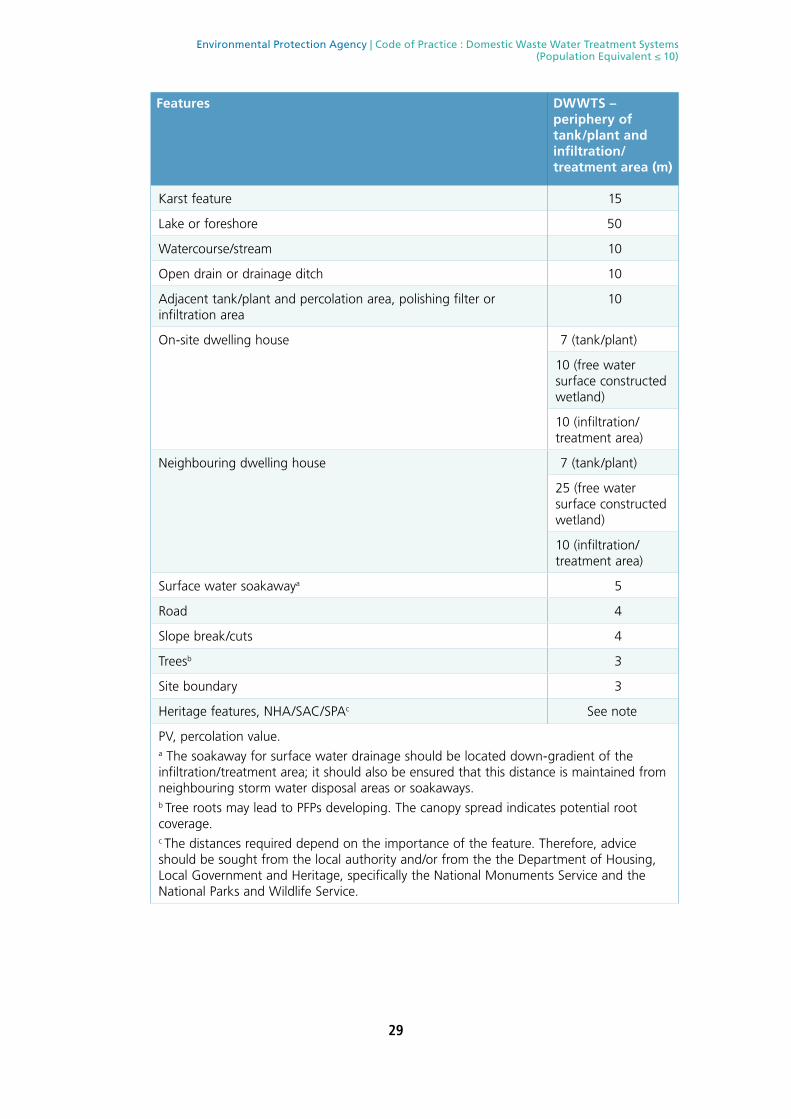
29
Environmental Protection Agency | Code of Practice : Domestic Waste Water Treatment Systems (Population Equivalent ≤ 10)
Features DWWTS – periphery of tank/plant and infiltration/treatment area (m)
Karst feature 15
Lake or foreshore 50
Watercourse/stream 10
Open drain or drainage ditch 10
Adjacent tank/plant and percolation area, polishing filter or infiltration area
10
On-site dwelling house 7 (tank/plant)
10 (free water surface constructed wetland)
10 (infiltration/treatment area)
Neighbouring dwelling house 7 (tank/plant)
25 (free water surface constructed wetland)
10 (infiltration/treatment area)
Surface water soakawaya 5
Road 4
Slope break/cuts 4
Treesb 3
Site boundary 3
Heritage features, NHA/SAC/SPAc See note
PV, percolation value.a The soakaway for surface water drainage should be located down-gradient of the infiltration/treatment area; it should also be ensured that this distance is maintained from neighbouring storm water disposal areas or soakaways.b Tree roots may lead to PFPs developing. The canopy spread indicates potential root coverage.c The distances required depend on the importance of the feature. Therefore, advice should be sought from the local authority and/or from the the Department of Housing, Local Government and Heritage, specifically the National Monuments Service and the National Parks and Wildlife Service.
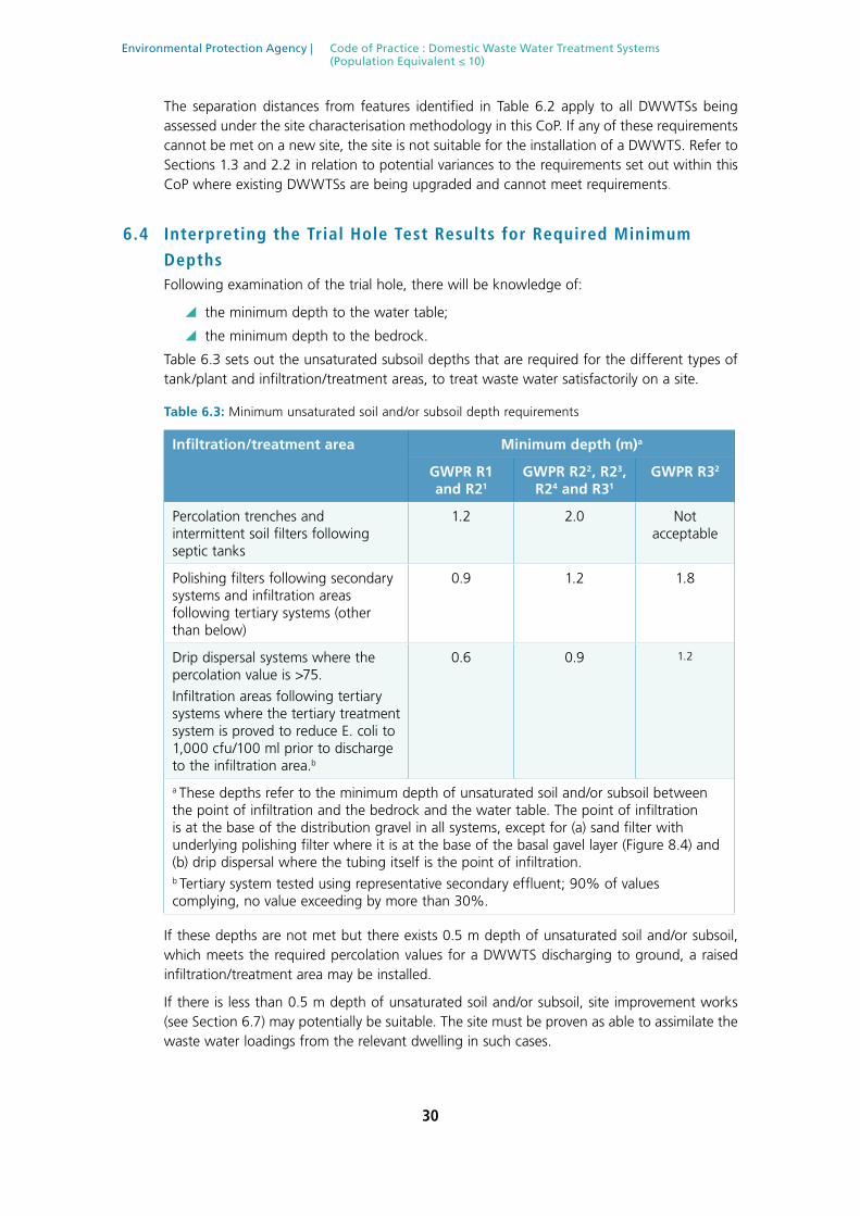
30
Environmental Protection Agency | Code of Practice : Domestic Waste Water Treatment Systems (Population Equivalent ≤ 10)
The separation distances from features identified in Table 6.2 apply to all DWWTSs being assessed under the site characterisation methodology in this CoP. If any of these requirements cannot be met on a new site, the site is not suitable for the installation of a DWWTS. Refer to Sections 1.3 and 2.2 in relation to potential variances to the requirements set out within this CoP where existing DWWTSs are being upgraded and cannot meet requirements.
6.4 Interpreting the Trial Hole Test Results for Required Minimum
DepthsFollowing examination of the trial hole, there will be knowledge of:
\ the minimum depth to the water table;
\ the minimum depth to the bedrock.
Table 6.3 sets out the unsaturated subsoil depths that are required for the different types of tank/plant and infiltration/treatment areas, to treat waste water satisfactorily on a site.
Table 6.3: Minimum unsaturated soil and/or subsoil depth requirements
Infiltration/treatment area Minimum depth (m)a
GWPR R1 and R21
GWPR R22, R23, R24 and R31
GWPR R32
Percolation trenches and intermittent soil filters following septic tanks
1.2 2.0 Not acceptable
Polishing filters following secondary systems and infiltration areas following tertiary systems (other than below)
0.9 1.2 1.8
Drip dispersal systems where the percolation value is >75.
Infiltration areas following tertiary systems where the tertiary treatment system is proved to reduce E. coli to 1,000 cfu/100 ml prior to discharge to the infiltration area.b
0.6 0.9 1.2
a These depths refer to the minimum depth of unsaturated soil and/or subsoil between the point of infiltration and the bedrock and the water table. The point of infiltration is at the base of the distribution gravel in all systems, except for (a) sand filter with underlying polishing filter where it is at the base of the basal gavel layer (Figure 8.4) and (b) drip dispersal where the tubing itself is the point of infiltration.b Tertiary system tested using representative secondary effluent; 90% of values complying, no value exceeding by more than 30%.
If these depths are not met but there exists 0.5 m depth of unsaturated soil and/or subsoil, which meets the required percolation values for a DWWTS discharging to ground, a raised infiltration/treatment area may be installed.
If there is less than 0.5 m depth of unsaturated soil and/or subsoil, site improvement works (see Section 6.7) may potentially be suitable. The site must be proven as able to assimilate the waste water loadings from the relevant dwelling in such cases.

31
Environmental Protection Agency | Code of Practice : Domestic Waste Water Treatment Systems (Population Equivalent ≤ 10)
6.5 Interpreting the Percolation Values of the Soil and SubsoilThe subsoil classifications from the trial hole should be broadly equivalent to the expected percolation test results. If there is not a good correlation then further examination should be undertaken to determine which assessment accurately reflects the suitability of the site to treat and dispose of the effluent. Design should then be based on the more appropriate of the two methods.
Following the determination of the percolation values for the site, Table 6.4 outlines the options available.
Table 6.4: Percolation Values
DWWTS Percolation value
Septic tank and percolation area 3–50
Secondary treatment system and soil polishing filter
Pumped or underlying gravity discharge (Options 1 and 2)
Gravity discharge, 500 mm wide trenches (Option 3)
3–75 (if installed at the surface, the subsurface PV must be
3–90)
Low-pressure pipe, 300 mm wide trenches (Option 4)
3–90
Drip dispersal system (Option 5)
3–120
Tertiary treatment system and infiltration area 3–75 (if installed at the surface, the subsurface PV must be
3–90)
If the percolation value is less than 3, the retention time in the soil and/or subsoil is too short to provide satisfactory treatment. Site improvement works comprising importation of soil and/or subsoil with a slower percolation rate and installation of a suitable DWWTS could be considered. Discharge to surface water may be an alternative but requires a Water Pollution Act licence from the local authority.
If the percolation value is greater than 120, the site is unsuitable for a DWWTS discharging to ground. Discharge to surface water may be an alternative but requires a Water Pollution Act licence from the local authority.
6.6 Selecting an Appropriate On-Site DWWTSAt this stage of the process the site characterisation is complete and, if the site is suitable, the types of on-site DWWTSs and the discharge options that are suitable for the site are known. These should all be recorded on the site characterisation form (see Appendix A). The conclusions of the site characterisation will dictate the type and range of system(s) and the design requirements.
When a site is deemed suitable for discharge to ground, the site assessor should make a recommendation as to the most appropriate on-site DWWTS for the particular site under assessment, including discharge route.
The information collected from the desk study and on-site assessment should be used in an integrated way to determine whether a DWWTS is feasible and, if it is, which one. If no portion of a site can meet the above criteria, then the site is not suitable for the installation

32
Environmental Protection Agency | Code of Practice : Domestic Waste Water Treatment Systems (Population Equivalent ≤ 10)
of a DWWTS discharging to ground. There could also be other factors that may render a site unsuitable for installation of a DWWTS for discharge to ground (e.g. presence of underground utilities, presence of particular sites within SACs, SPAs or NHAs, sites on floodplains), so the site characterisation should be considered in full.
If the site is suitable for a DWWTS, the type of system that is appropriate and the optimal final disposal route for the treated waste water are determined at this stage. Assuming that the criteria outlined above can be met on a site, a DWWTS is selected on the basis of whether or not:
\ the area hosting it has a suitable slope;
\ the location of the DWWTS meets all required minimum separation distances;
\ beneath the infiltration/treatment area, the required depth of unsaturated soil and/or subsoil is present above the bedrock and the water table;
\ the location hosting the DWWTS has the required percolation values for the DWWTS to be installed;
\ there are any other issues arising from the site characterisation.
Further to these criteria, the following factors may also be taken into account in selecting the appropriate DWWTS:
\ simple/passive design;
\ longevity;
\ capital cost;
\ running cost;
\ maintenance cost;
\ required de-sludging frequency;
\ power requirements;
\ carbon footprint;
\ unusual flow patterns or unusual hydraulic and/or wastewater strengths;
\ requirement for enhanced nutrient reduction.
In the case of selecting a system for a holiday home, consideration should be given to a system that can adequately deal with periods of inactivity, i.e. when the house is unoccupied for a prolonged period. Passive systems, which require the minimum amount of maintenance, are preferred. It is recommended that biodegradable cleaning agents be considered for use in holiday homes.
In all cases, the minimum design/construction/installation requirements should be included in the site characterisation report.
The type, location and installation requirements for each system should be very clearly set out in the report, highlighting the importance of site levels and the integration of finished floor levels with the site assessment and cross-sections showing drainage falls, soil depth below pipe inverts, etc. In all cases additional attention should be given to providing cross-sections indicating invert levels of pipework etc.
If additional pages are required, these should be submitted with the site characterisation form. The site characterisation form and report should also include relevant photographs taken during the assessment process, as well as relevant maps, as specified on the form.

33
Environmental Protection Agency | Code of Practice : Domestic Waste Water Treatment Systems (Population Equivalent ≤ 10)
6.7 Site Improvement WorksIn certain circumstances, a site that is intended for a single house development will present particular difficulties arising out of the site assessment, and the in situ soil and/or subsoil will not have the conditions necessary for discharge to ground. Some sites may have a high water table, or an insufficient subsoil depth owing to bedrock close to the surface, or a layer of unsuitable subsoil (at the surface, different to that at depth) for the purposes of treatment and percolation of the pre-treated waste water from a tank or plant. It may be possible in some such cases to render the site suitable for development after carrying out specific engineering works known as ‘site improvement works’.
It should be noted that the importation of suitable soils and/or subsoils for the construction of any component of a percolation area, polishing filter, low-pressure pipe distribution system or drip dispersal system within a DWWTS where a site has been deemed suitable for discharge to ground, including those that may form part of raised percolation areas, raised polishing filters or other mound systems, is not classed as site improvement works.
Site improvement works should be carried out only under the supervision of an appropriately trained and qualified person, as such works are technically difficult to carry out correctly. Detailed design procedures appropriate for site improvement works are available in drainage manuals (e.g. Mulqueen et al., 1999). In many cases site improvement works will still not be sufficient to enable the site to be used for a system incorporating discharge to ground.
When importing soils and/or subsoils onto sites as part of either site improvement works or the construction of a DWWTS, it is necessary to perform testing of each 300 mm layer while the process of emplacing lifts of soil progresses. After each lift is placed, percolation tests should be carried out. A 150 mm square hole is excavated to a depth of 150 mm in the placed soil. After pre-soaking to completely wet the soil, 0.5 litres of water is poured into the hole and the time in minutes for the water to soak away is recorded. This time should be between 10 minutes and 2 hours.
Examples of sites where site improvement works will not be acceptable are:
\ sites where the slope exceeds 1:8;
\ sites where the average percolation value from the three conducted tests is greater than 120, indicating a high risk of ponding;
\ sites where separation distances cannot be satisfied.
If site improvement works are being proposed on any site, it is recommended to consult the local authority before such works commence.

34
Environmental Protection Agency | Code of Practice : Domestic Waste Water Treatment Systems (Population Equivalent ≤ 10)
7. SEPTIC TANK SYSTEMSA septic tank functions as a two-stage primary sedimentation tank, removing most of the suspended solids from the waste water, thus providing ‘primary’ treatment. This removal is accompanied by a limited amount of anaerobic digestion. The infiltration/treatment area provides most of the ‘secondary’ and ‘tertiary’ treatment from such systems in the percolation trenches or intermittent filter bed and the underlying subsoil.
The waste water from the septic tank may be distributed to a suitable soil and/or subsoil percolation area, which acts as a bio-filter. The percolation pipes may be subsurface or at ground level using in situ soil and/or subsoil for treatment, and the performance of septic tanks and percolation areas in treating domestic effluent relies primarily on the subsoil attenuation capability of the percolation area.
A biomat forms at the base of a percolation trench; this is a biologically active layer that contains a complex community of microorganisms with associated accumulated organic substances that act to treat the effluent. The biomat controls infiltration at the base of the drainage trench, and soil characteristics govern the rate at which water percolates through the subsoil. As the waste water flows into and through the subsoil, it undergoes surface filtration, straining, physico-chemical interactions and microbial breakdown. After percolating through a suitably designed and maintained percolation area, the waste water is suitable for discharge to groundwater.
Failure of a septic tank and percolation area to function properly is generally due to poor construction or installation or to operation in an area of unsuitable ground conditions, or to the use of a soakaway instead of a properly designed percolation area. Soakaways (also termed soakage pits, soakholes or soakpits) are no longer considered an acceptable infiltration/treatment area for the disposal of domestic waste water on-site. Refer to Sections 1.3 and 2.2 above in relation to potential variances to the requirements set out within this CoP where existing DWWTSs are being upgraded and cannot meet requirements.
The attributes of septic tanks are outlined in Table 7.1.
Table 7.1: Attributes of a typical septic tank
A properly constructed septic tank will:
Retain and remove ≥50% of solids
Allow some microbial decomposition
Accept sullage (i.e. water from baths, wash hand basins)
Accept water containing detergents (e.g. from a washing machine, dishwasher)
Reduce clogging in the percolation area
Not fully treat domestic waste water
Not work properly if not regularly maintained
Not significantly remove microorganisms
Not remove >15–30% of the BOD
Not operate properly if pesticides, paints, thinners, solvents, excess disinfectants or household hazardous substances are discharged to it
Not accommodate sludge indefinitely
Not operate properly if surface waters (i.e. from roofs, parking areas) are discharged to it

35
Environmental Protection Agency | Code of Practice : Domestic Waste Water Treatment Systems (Population Equivalent ≤ 10)
7.1 Septic Tanks All septic tanks must comply with the requirements of the relevant parts of I.S. EN 12566; Part 1 for prefabricated septic tanks and Part 4 for septic tanks assembled on site from prefabricated kits. All compliant septic tanks must be installed in accordance with the manufacturer’s instructions.
A plan and section of a typical septic tank and percolation area layout are given in Figure 7.1.
Figure 7.1: Plan and section of a typical septic tank system
Dwelling
7m (min)
10m(min)
18m(max)
Percolation Area
Distribution Device
Septic Tank
Manhole(change in direction
& inspection)
2m
2.5mc/c
Vent Stack
Vents
100mm 100mm
Manhole
Ground Level
GeotextileMembrane
Gravel 2m (min)
2.50m (min c/c)
550mm
300mmminimum
100mm - 110mmpipe with 8mm holes at 4, 6 and 8 o’clockat 75mm centres
A
A A
A

36
Environmental Protection Agency | Code of Practice : Domestic Waste Water Treatment Systems (Population Equivalent ≤ 10)
7.1.1 Septic Tank Design Capacity
The septic tank should be of sufficient volume to provide a retention time for settlement of the suspended solids while reserving an adequate volume for sludge storage (Figure 7.2). The volume required for sludge storage is the determining factor in sizing the septic tank, and this depends on the potential occupancy of the dwelling, which should be estimated from the maximum number of people that the house can accommodate, as derived from the number of bedrooms (see Table 3.2).
The septic tank design capacity should be calculated from the following formula:
C = (150 × PE) + 2000
where C is the design capacity of the tank (litres) and PE is the design population equivalent, with a minimum of four persons.
A minimum design capacity of 2600 litres (2.6 m3) should be provided on sites where the population is four or less.
S.R. 66 requires that the septic tank nominal and usable capacities be declared. The nominal capacity is usually rounded down and expressed in 1 m3 intervals, with the usable capacity declared in litres.
The declared usable capacity of the septic tank being installed on site must be no less than the calculated design capacity.
An effluent filter on the outlet is recommended to protect the ‘downstream’ element of the DWWTS from carryover of sludge solids.
Figure 7.2: Typical drawing of a septic tank certified to I.S. EN 12566, Part 1 or 4, complying with requirements of SR 66
Ventilation Cowls
Freeboard
Outlet toPercolationArea
Ground Level
Gas BuoyedFlotation
TWL
Sedimentation of Solids
Scum Layer
Liquid Layer
Sludge Layer
Flow Through
Inlet from house
Lid Lid
T-Piece T-Piece
PrimaryChamber
SecondaryChamber

37
Environmental Protection Agency | Code of Practice : Domestic Waste Water Treatment Systems (Population Equivalent ≤ 10)
7.2 Percolation Areas
7.2.1 General
The most important component of a septic tank system is the percolation area (which is an infiltration/treatment area) as it provides most of the treatment of the waste water effluent. I.S. CEN/TR 12566 Part 2 Small Wastewater Treatment Systems for up to 50 PT – Soil Infiltration Systems is a technical report giving guidance for soil infiltration systems to be used with small waste water treatment systems. The contents of that document have been taken into account in the preparation of this CoP. Installation guidelines and layout options are provided in Chapter 11.
The septic tank effluent flows by gravity into a distribution device, usually a distribution box, that distributes the flow evenly into a number of percolation pipes in the percolation trenches (see Section 11.3 for more details). The depth to the invert of the percolation trench may vary and is dependent on the required minimum depth of unsaturated soil and/or subsoil beneath the base of the trench gravel and above the bedrock and the water table. This depth is 1.2 m when the GWPR is R1 or R21 (Figure 7.3), or 2m for most other response types (see Table 6.3). Septic tank and percolation areas are not acceptable in areas of GWPR R32, i.e. in the inner protection zone of source protection areas with ‘extreme’ groundwater vulnerability.
Waste water flows out through orifices in the percolation pipes into a gravel underlay, which acts both to distribute and to provide a medium for initial treatment of the effluent. The effluent then percolates into the soil and/or subsoil, where it undergoes further biological, physical and chemical interactions that treat the contaminants. For effective treatment, the waste water must enter the soil and/or subsoil, yet it is equally important that the waste water remains long enough in this material to allow treatment to take place.
Figure 7.3: Section of a typical percolation trench following a conventional septic tank
7.2.2 Hydraulic Loading Rates
The hydraulic loading and the rate of flow into the sides and base of the trench control the residence time, so are primarily controlled by the biomat that forms on the floor and sides of the trench rather than by the subsoil itself. The percolation values, measured as they are on in situ subsoil using clean water, cannot be directly used for the design of the hydraulic distribution system and length of percolation trench. Rather, a long-term acceptance rate (LTAR) is defined for the design whereby the length of percolation trench is calculated as a function of the number of persons for which the house is designed. A loading rate of 16.7l/ m2.d is recommended for waste water being discharged into a percolation area and
Base of thePercolation Trench
UnsaturatedUndisturbed
Subsoil
Ground Level
GeotextileMembrane
300mm minimum
850mm minimum
1,200mm or 2,000mm minimum above water table and/or bedrockdepending on the groundwaterprotection response (see Table 6.3)
300mm
100mm
150mm
PercolationPipe
500mm
Gravel
300mm
Proposed Invertof Percolation Pipe
Water level
T Test Hole
400mm
SubsurfacePercolationTest Hole
Ground Level
300mm
400mm
SurfacePercolationTest Hole
Water level
100mm
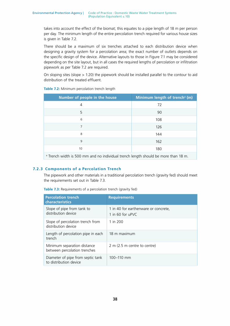
38
Environmental Protection Agency | Code of Practice : Domestic Waste Water Treatment Systems (Population Equivalent ≤ 10)
takes into account the effect of the biomat; this equates to a pipe length of 18 m per person per day. The minimum length of the entire percolation trench required for various house sizes is given in Table 7.2.
There should be a maximum of six trenches attached to each distribution device when designing a gravity system for a percolation area; the exact number of outlets depends on the specific design of the device. Alternative layouts to those in Figure 7.1 may be considered depending on the site layout, but in all cases the required lengths of percolation or infiltration pipework as per Table 7.2 are required.
On sloping sites (slope > 1:20) the pipework should be installed parallel to the contour to aid distribution of the treated effluent.
Table 7.2: Minimum percolation trench length
Number of people in the house Minimum length of trencha (m)
4 72
5 90
6 108
7 126
8 144
9 162
10 180
a Trench width is 500 mm and no individual trench length should be more than 18 m.
7.2.3 Components of a Percolation Trench
The pipework and other materials in a traditional percolation trench (gravity fed) should meet the requirements set out in Table 7.3.
Table 7.3: Requirements of a percolation trench (gravity fed)
Percolation trench characteristics
Requirements
Slope of pipe from tank to distribution device
1 in 40 for earthenware or concrete,
1 in 60 for uPVC
Slope of percolation trench from distribution device
1 in 200
Length of percolation pipe in each trench
18 m maximum
Minimum separation distance between percolation trenches
2 m (2.5 m centre to centre)
Diameter of pipe from septic tank to distribution device
100–110 mm

39
Environmental Protection Agency | Code of Practice : Domestic Waste Water Treatment Systems (Population Equivalent ≤ 10)
Percolation trench characteristics
Requirements
Percolation pipesa 100 mm bore, perforated (typically at 4, 6 and 8 o’clock) smooth wall PVC drainage pipes with perforations of 8 mm diameter at about 75 mm centres along the pipe or pipes with similar hydraulic properties.
Maximum of six pipes per distribution device
Width of percolation trench 500 mm
Depth of percolation trench Ideally, about 850mmb below ground surface depending on site (as per Figures 7.1 and 7.3)
Depth of unsaturated soil and/or subsoil beneath percolation trench and above the bedrock and the water table
Minimum 1.2 m for GWPRs of R1 or R21. Minimum 2.0 m for GWPRs of R22, R23, R24, R31 or R32
Backfilling of percolation trench (see Figure 7.1)
300 mm of 12–32 mm washed gravel or broken stone aggregate on invert; pipe laid at a 1 in 200 slope surrounded by 12–32 mm clean washed gravel or broken stone aggregate and with 150 mm of similar aggregate over pipe; geotextile layer followed by topsoil to ground surface
Geotextile Geotextile should be in accordance with EN ISO 10319
Access/inspection points and vents These are recommended for the ends of the percolation pipes. The covers should be visible and installed to prevent entry of water. They may also be used for rodding or scouring purposes
a Before installation the holes in the percolation pipe should be inspected to check that they are the correct size and free from debris.
b The percolation pipes may be located at a shallower depth, provided that a minimum of 450 mm of material is placed above the pipes to provide the required protection against damage from above.
7.2.4 Raised/Mounded Percolation Areas
A standard percolation area (Figure 7.3) requires a standard depth to bedrock and water table of 2.05 m. Where this is not available, a raised/mounded percolation area could be considered. In this case, the gravel trenches and pipework are raised to ground level and mounded element comprises the cap (Figure 7.4). The in situ soil and/or subsoil are used to treat the effluent from the septic tank.
Depending on site contours, distribution occurs either by gravity via a distribution device or by pumping to a distribution device via a stilling chamber. The top of the trench gravel should not extend above ground level and, on sites with a relatively shallow depth to the bedrock and/or the water table, alternative options such as those outlined in Chapter 8 may be considered.

40
Environmental Protection Agency | Code of Practice : Domestic Waste Water Treatment Systems (Population Equivalent ≤ 10)
Figure 7.4: Section of a typical raised/mounded percolation area following a conventional septic tank
Base of thePercolation Trench
UnsaturatedUndisturbed
Subsoil
Ground Level
GeotextileMembrane
300mm
850mm
300mm
100mm
150mm
Percolation Pipe
500mm
2m(distance between trenches)
Top of “Mound”
Gravel
1,200mm or 2,000mm minimum above water table and/or bedrockdepending on the groundwaterprotection response (see Table 6.3)

41
Environmental Protection Agency | Code of Practice : Domestic Waste Water Treatment Systems (Population Equivalent ≤ 10)
8. SECONDARY TREATMENT SYSTEMS RECEIVING SEPTIC TANK EFFLUENT Filtration systems that receive septic tank effluent directly are used to provide additional treatment and are therefore considered to be secondary treatment systems. They comprise:
\ intermittent soil filter systems;
\ intermittent sand filter systems;
\ constructed wetlands;
\ packaged media filters.
As with septic tanks discharging to percolation areas, an effluent filter is recommended in or after the tank discharging to intermittent filter systems, constructed wetlands and packaged media filters.
A polishing filter, low-pressure pipe distribution system or drip dispersal system is required to be installed after most of these systems (except intermittent soil filters) to allow for further treatment of the waste water and to convey the treated waste water into the ground.
The typical layout for the treatment of waste water using an intermittent filter or a constructed wetland is illustrated in Figure 8.1. Most will require pumping, and an appropriately trained and qualified person with relevant experience in the area should carry out their design and construction. If requested, a full set of calculations should be available for the design of the system.

42
Environmental Protection Agency | Code of Practice : Domestic Waste Water Treatment Systems (Population Equivalent ≤ 10)
Figure 8.1: Example of a typical intermittent filter system or constructed wetland system
8.1 Intermittent FiltersThe waste water from the septic tank should be applied uniformly over the plan area of the intermittent soil or sand filter at intervals such that it percolates down through the entire filter at a rate that optimises contact (and therefore treatment) with the biofilms coating the media.
An even distribution may be obtained by pumping the waste water through evenly spaced lateral pipes, with evenly spaced orifices embedded in distribution gravel, as detailed in Tables 8.1 and 8.2. Dosing frequencies are related to the type of filter medium. A minimum dosing frequency of four times daily is recommended, which should ideally be applied at equal intervals by means of a timer. Dosing tanks (pump sumps) should be sized according to the volume of effluent production that is equivalent to one day’s volume from the household. Intermittent soil filters may be gravity fed where site contours allow (see further below). Intermittent sand filters may be fed by a gravity siphon device that effectively acts as a pressurised system or by intermittent dosing via pump-pressurised distribution (see further below).
Other configurations and design distribution system specifications, such as rigid pipe pressure networks, are generally used, but design is on a case-by-case basis. Hydrodare pipes or polyethylene pipes as perforated laterals are not permitted for use, and drilling orifices in pipes
PumpSump
0.3m toedge ofgravel
0.3m approx.,usually half
lateral spacingdistance
end of pipes capped*
*ends of Infiltration Pipes may also be joined
0.6m spacing minimumdependent on
specialistdesign
Minimum 25mm internal
Orifice spacingdependent on
specialistdesign
4-6mm orifices

43
Environmental Protection Agency | Code of Practice : Domestic Waste Water Treatment Systems (Population Equivalent ≤ 10)
during installation is not encouraged. The design should be in accordance with best practice and in line with published design manuals and should be completed by an appropriately trained and qualified person.
Figure 8.2: Example of a pumped distribution system
8.1.1 Intermittent Soil Filter Systems
Intermittent soil filter systems may be used in situations where relatively difficult site conditions are encountered, such as a relatively shallow water table, an insufficient subsoil depth, an unusual site shape or a percolation value of 51–75. The main difference between these filters and percolation areas is that the filters use a bed of gravel to distribute the septic tank effluent, whereas percolation areas distribute the effluent beneath the ground surface via trenches. As well as this, a septic tank can be installed using these filter systems where the percolation values are 51–75.
An intermittent soil filter system may be developed through the use of a gravel distribution layer over imported soil with favourable characteristics or through the use of in situ soil and/or subsoil where the upper layer has been removed and replaced by a gravel distribution layer. In both cases the septic tank effluent is usually distributed over the intermittent filter using a pressure (i.e. pumped) distribution system, although gravity feed may be used where the site contours allow. Such filters do not require an additional polishing stage, as this is built in beneath the filter gravel in the underlying soil and/or subsoil.
An intermittent soil filter may be placed in or on the ground in a number of different design configurations:
1. It may be placed in the ground with a distribution system installed at a shallow depth.
2. It may be arranged with the distribution system at ground level (Figure 8.3).
3. It may be raised with the distribution system above the normal ground level.
In the last two cases, intermittent soil filters are sometimes termed mounded systems. In all cases the required depths beneath the filter gravel as outlined in Table 6.3 must apply.
Dwelling
Intermittent Filter,Media Filter orConstructed wetland
7m (min)
10m(min)
10m(max)
Offset Soil Polishing Filteras per Section 10.1
Pump Sump(if not by gravity)
Septic Tank
VentStack Manhole

44
Environmental Protection Agency | Code of Practice : Domestic Waste Water Treatment Systems (Population Equivalent ≤ 10)
A typical design, subject to the specifications outlined by an appropriately trained and qualified designer, is set out in Table 8.1.
Table 8.1: Typical intermittent soil filter requirements
Intermittent soil filter characteristics
Requirements
Minimum soil thickness beneath the distribution gravel (see Table 6.3)
1.2 m for GWPRs of R1 or R21
2.0 m for GWPRs of R22, R23, R24 or R31
Soil percolation valuea In situ material should have a percolation value between 3 and 75
Hydraulic loading 4 l/m².d on plan area of filter
[150 × PE / 4 = minimum area (m2) of intermittent soil filter]
Design criteria:b
Soil layers Lifts of 300 mm of soil (lightly compacted if imported)
Gravel protection layer 150 mm of 12–32 mm washed gravel or broken stone
Infiltration laterals Minimum 25 mm ø PVC with 4–6 mm orificesc at 0.3–1.0 m spacings where pumped; 100 mm ø PVC with 8 mm orifices at 75 mm spacings, maximum 18 m length,
where gravity
Gravel distribution layer 250 mm of 12–32 mm washed gravel
Lateral centres separation Maximum of 0.6 m (pumped); 2.5 m (gravity).
Geotextile In accordance with EN ISO 10319
Underdrain/collection system required where proposed discharge is to surface water
Washed durable gravel or stone of 12–32 mm, beneath the soil of the intermittent soil polishing filter
Slotted or perforated drainpipe 75–100 mm øSlope 0–1%
Dosing frequency As many doses as possible, and ideally a minimum of four times per day using timed dosing (at equal time intervals for optimum treatment efficiency)
Pumping system Pumps should be installed in a separate pumping chamber and only suitable waste water treatment pumps with a minimum free passage of 10 mm should be used
Zoned regions Zoning of regions may be provided when designing large pipe network systems using hydraulic valves or similar. Providing ball valves or gate valves to isolate sections of all pipe networks is recommended to facilitate maintenance
Access/inspection points; pressure regulating and flushing/scouring valves
Recommended to be installed in the distribution system for rodding or scouring purposes. These vertically attached pipes to the ends of laterals should extend to an inspection chamber and can also be used as a point to measure the back pressure of the system

45
Environmental Protection Agency | Code of Practice : Domestic Waste Water Treatment Systems (Population Equivalent ≤ 10)
Intermittent soil filter characteristics
Requirements
Side sealing: at surface (or appropriate depth)
Topsoil on top and the vertical sides should be protected by a geotextile
Base sealing No sealer required
Ground base layer in mound systems to be ploughed/tilledd
Covering Geotextile over the gravel distribution layer
300 mm topsoil over geotextile
a If constructing a system above ground then any imported soil and/or subsoil should have a percolation value between 3 and 30.b Owing to variations in the discharge rating of pumps available on the market, it is important to correctly match the orifice diameter and the lateral diameter in the distribution system to the pump, thus ensuring even and effective distribution of the hydraulic load across the filter area. This means a requirement for a ‘bespoke’ design by a competent person in accordance with internationally recognised design parameters, e.g. US EPA Design Manual, 2002.c The infiltration pipe should be laid with the holes facing downwards (I.S. CEN/TR 12566-2: 2005).d In the case of mounded systems, the base should be roughened to minimise compaction and smearing of the soil (I.S. CEN TR 12566-2: 2005).
Figure 8.3: Example of a typical Pumped/Pressurised raised intermittent soil filter with pipes at ground level
GeotextileMembrane
Ground Level
Ground Level
Ground Level
0.3m
Distribution Pipe
From Septic Tank
0.3m
Height above ground dependson available unsaturatedsubsoil thickness. Filter mayalso be constructed undergroud
Pump Sump
Infiltration Pipes 25mm
150mm
250mm
1,200mm or 2,000mm minimum above water table and/or bedrock depending on the groundwater protection response (see Table 6.3)
Topsoil
Subsoil
GeotextileMembrane

46
Environmental Protection Agency | Code of Practice : Domestic Waste Water Treatment Systems (Population Equivalent ≤ 10)
8.1.2 Intermittent Sand Filter Systems
Intermittent sand filters consist of one or more beds of graded sand underlaid at the base by a gravel or permeable soil layer to prevent outwash or piping of the sand, and the treatment of the waste water takes place under predominantly unsaturated and aerobic conditions. They are an effective form of on-site treatment and the area required for the filter is significantly less than that required for an intermittent soil filter or a soil and/or subsoil percolation area. It must be noted, however, that these systems must be followed by an underlying or offset soil polishing filter, low-pressure pipe distribution system or drip dispersal system, to convey the treated waste water into the ground.
Two types of intermittent sand filters are used, namely soil covered and open:
1. Soil-covered intermittent sand filters may be underground, part underground and part overground (Figure 8.4) or overground. The last two, as with raised intermittent soil filters, may be termed mound systems.
2. Open intermittent sand filters are constructed similarly to the covered sand filters, but without the soil cover, i.e. the gravel distribution layer is exposed at the surface to allow for inspection and periodic maintenance. They are preferably underground with the top of the gravel at ground surface.
Intermittent sand filters are single-pass, slow sand filters, which provide secondary treatment via the biofilms that naturally develop on the inert sand media. Typical design details are shown in Table 8.2. These filters can be designed using stratified layers of diminishing-sized media with depth, in which case the required depth of sand is 650 mm, or they can comprise monograde sand, in which case the required depth of sand is 900 mm. Both types of filter must be underlaid by a layer of gravel to prevent outwash or piping of the sand and overlaid by gravel distribution and protection layers. The basal layer of these filters must be vented. The infiltration pipe should be laid with the holes facing downwards as per I.S. CEN TR 12566-2:2005. Phosphorus removal in such filters is dependent on sand mineralogy, although it should be noted that the ability of any sand to remove phosphorus is finite (Vohla et al., 2011).
Even distribution across the entire surface area of the intermittent sand filter is critical, and these can be fed either by a gravity siphon device that effectively acts as a pressurised system or by intermittent dosing via pump-pressurised distribution. In soil-covered filters, a non-clogging geotextile is used to separate the soil cover from the distribution gravel. The waste water from the septic tank flows through the sand bed beneath this, where it receives treatment (Figures 8.4 and 8.5).
In a soil-covered intermittent sand filter, both the distribution gravel over the sand and the drain filter gravel (where present) under the sand are vented; the vents are extended vertically above ground or mound level and capped with a cowl or grid. In an open filter only the drain filter gravel (where present) is vented.

47
Environmental Protection Agency | Code of Practice : Domestic Waste Water Treatment Systems (Population Equivalent ≤ 10)
Table 8.2: Typical intermittent sand filter specifications
Intermittent sand filter characteristics
Requirements
Minimum sand thickness 0.65 m for stratified filters
0.9 m for monograde filters
Minimum soil and/or subsoil thickness (see Table 6.3 also)
This is measured from beneath the basal gravel layer in the case of a sand filter with underlying soil polishing filter.
The same depths are also required for an offset soil polishing filter measured from the base of the soil polishing filter distribution gravel or drip tubing.
0.9 m for GWPR R1 and R21
1.2 m for GWPR R22, R23, R24 and R31
1.8m for GWPR R32
Sand grain sizes Soil covered – D10 range from 0.7 to 1.0 mm
Open filters – D10 range from 0.4 to 1.0 mm
Uniformity coefficients (D60/D10) < 4
Hydraulic loading The intermittent sand filter itself may be dosed up to a maximum of 30 l/m2.d
[150 × PE / 30 = minimum area (m2) of intermittent soil filter]
Where the intermittent sand filer is discharging to an offset soil polishing filter, the soil polishing filter should be sized in accordance with Chapter 10.
Where the intermittent sand filter is discharging directly to an underlying soil polishing filter, the soil polishing filter should be sized in accordance with Chapter 10 (Table 10.1, Option 1). The intermittent sand filter should be the same size as the underlying soil polishing filter (see Figure 8.4).
Design criteria:
Sand layers A number of beds of graded sand
Gravel protection layer 150 mm of 12–32 mm washed gravel or broken stone
Infiltration laterals Minimum 25 mm PVC with 4–6 mm orificesa at a maximum spacing of 0.3 m; exact orifice sizing and spacing to be determined by an appropriately trained and qualified person
Gravel distribution layer 250 mm of 12–32 mm washed gravel or broken stone
Lateral centres separation Maximum 0.6 m

48
Environmental Protection Agency | Code of Practice : Domestic Waste Water Treatment Systems (Population Equivalent ≤ 10)
Intermittent sand filter characteristics
Requirements
Underdrain/collection system Washed durable gravel or stone of 12–32 mm, at the base of the sand polishing filter
Slotted or perforated drainpipe of 75–100 mm Æ
Slope 0–1%
Dosing frequency (controlled by on/off levels on pump)
Frequent small doses spread over 24 hours are preferable to a few large doses that flood the media; always designer-specific, but recommend a minimum of three times per day using timed dosing, based on a full occupancy day; a minimum of five times the pipe network volume should be dosed
Pumping system The pump capacity should be sufficient to supply the total dynamic head of the sand filter distribution pipework
Zoned regions Zoning of regions may be provided when designing large pipe network systems using hydraulic valves or similar. Providing ball valves or gate valves to isolate sections of all pipe networks is recommended to facilitate maintenance
Side sealing:
Mound system
Topsoil on top and the vertical sides should be protected by a geotextile
Below-ground system Impermeable liner in free-draining in situ subsoils
Base sealing:
Offset polishing filter
Impervious soil or synthetic liner with collection system
Covering:
Soil covered
Geotextile (in accordance with EN ISO 10319) over the gravel distribution layer and 300 mm topsoil over geotextile
Open None
Venting
Soil covered
Open filter
Both distribution gravel and drain filter gravel are vented
Drain filter gravel is vented
Access/inspection points; pressure regulating and flushing/scouring valves
Recommended to be installed in the distribution system for rodding/scouring purposes. These vertically attached pipes to the ends of laterals should extend to an inspection chamber and can also be used as a point to measure the back pressure of the system
a The infiltration pipe should be laid with the holes facing downwards (I.S. CEN.TR 12566, Part 2).

49
Environmental Protection Agency | Code of Practice : Domestic Waste Water Treatment Systems (Population Equivalent ≤ 10)
Figure 8.4: Example of a typical below ground intermittent sand filter system with underlying subsoil polishing filter. See table 8.2 regarding sizing
Figure 8.5: Example of a typical stratified sand filter
8.1.3 Constructed Wetlands
‘Constructed wetland’ is the generic term used to describe both (gravel- and sand-based) subsurface flow horizontal and vertical flow reed bed systems, as well as free surface flow soil-based constructed wetlands.
GeotextileMembrane
Ground Level
Ground Level
Ground Level
Topsoil 0.3m
Topsoil
Infiltration Pipes
Distribution Pipe
From Septic Tank
0.3m
900mm
900mm to 1,800mm depending on groundwater protection response
(see table 6.3
Sand Filter
MonogradeSand Filter
Graded layers of sandPump Sumpor
StratifiedSand Filter 650mm
Basal gravellayer
25mm
150mm
250mm
Topsoil
Sand
GeotextileMembrane
200 mm sand (0.4-1.4mm)
250mm distribution gravel25mm
Vent (for open filters only)
Maximum 10mm gravel(i.e. 6mm-10mm)
Offset to Polishing Filter or Surface Water(via collection sump)
75 mm pea gravel (10-20 mm)
75 mm pea gravel (10-20 mm)
150 mm sand (0.1-0.5 mm)
150 mm sand (0.1-0.5 mm)
100mm
From PumpSump
200 mm filter gravel

50
Environmental Protection Agency | Code of Practice : Domestic Waste Water Treatment Systems (Population Equivalent ≤ 10)
The main difference between a constructed wetland and other filter systems is the planting of vegetation (reeds etc.) in the media, where the thick root mass adds an additional pollutant-attenuation process, owing to complex microbiological interactions around the root zones, as well as an additional uptake and production of biomass in the vegetation. In the wetland, the waste water from the septic tank undergoes secondary treatment by a combination of physical, chemical and biological processes that develop through the interaction of the plants, the growing media (gravel) and microorganisms.
The plants used are emergent macrophytes, the most notable of which is the common reed (Phragmites australis). Other plants species used are from the genera Iris, Typha, Sparganium, Carex, Schoenoplectus and Acorus. Planting should occur in blocks of plant species at a density of four to five plants per square metre. A mixing of plant species is encouraged to promote diversification in the system. Constructed wetlands can be designed to fit aesthetically within the landscape.
Both reed bed systems and soil-based constructed wetlands should be sealed by a geomembrane or a geosynthetic clay liner (permeability at least k = 1.0 x 10⁻⁸ m/s). Only waste water from the septic tank should be allowed to enter the wetlands, i.e. no collected rainwater or surface water should be diverted into them.
The design of a reed bed or soil-based constructed wetland is site-specific. General guidance on constructed wetlands and reed beds as open filters with reeds can be found in I.S. CEN/TR 12566 Part 5 Small Wastewater Treatment Systems for up to 50 PT – Pre-treated effluent filtration systems. All constructed wetlands require periodic maintenance, which is detailed in Chapter 11.
If being used for secondary treatment as part of a DWWTS, all constructed wetlands should be designed for a minimum of 5 PE. The area required is equivalent to 4–20 times the PE (DEHLG, 2010; Table 8.3), depending on the type of wetland.
Other design considerations are included in Table 8.3. If discharging into surface water under licence, the sizing of these treatment systems is ultimately dependent on the quality of the receiving water and therefore increased sizes are required in nutrient-sensitive areas.
Table 8.3: Criteria for constructed wetland systems receiving septic tank effluent
System type Area required (m2/PE)
Minimum system size
(m2)
Loading rates (l/m2 per dose)
Minimum length-to-width ratio
Horizontal flow reed bed – gravel
5 25 – 3 : 1
Vertical flow reed bed – gravel
4 20 8 (maximum) 2.5 : 1
Vertical flow reed bed – sand
4 20 5–15 (for 2–5 doses per day)
2.5 : 1
Free water surface (soil-based) constructed wetland
20 100 – 5 : 1

51
Environmental Protection Agency | Code of Practice : Domestic Waste Water Treatment Systems (Population Equivalent ≤ 10)
For wetland systems on sloping ground, it can be beneficial to divide the required bed area into smaller beds. Multiple beds may increase flexibility, enabling resting and maintenance of beds to be more easily carried out. Other treatment equipment, e.g. storage ponds, maturation ponds and willows, may be added to the system to enhance further treatment. The landscape setting may influence the design of these systems.
8.1.4 Horizontal Flow Reed Beds
The most common type of reed bed is the subsurface horizontal flow reed bed, where the waste water is maintained below the surface of the wetland media. In a horizontal flow reed bed, waste water is introduced at one end of a flat or gently sloping bed of reeds (slope with a slight fall of approx. 1%) set within gravel and flows across this bed to the outlet pipe. This adjustable discharge outlet controls the level of the water in the horizontal flow reed bed. Particular attention should be paid to the bed’s hydraulic distribution with respect to the inlet configuration and the aspect ratio. Horizontal subsurface flow reed beds are regarded as especially good in the removal of BOD5, suspended solids and pathogenic organisms. Figure 8.6 illustrates a typical gravel-based horizontal subsurface flow reed bed.
Figure 8.6: Example of a typical Horizontal subsurface flow reed bed
8.1.5 Vertical Flow Reed Beds
In a vertical flow reed bed, waste water is intermittently dosed uniformly over the media bed by a network of pressurised distribution pipes. It gradually drains vertically into a drainage collection network at the base of the support media. These drainage pipes should be aerated by means of a perforated ventilation pipe extending into the atmosphere. As the waste water drains vertically, air re-enters the pores of the media, thus maintaining the aerobic conditions in the filter media and aiding the treatment. As a result, vertical flow reed bed systems provide as effective treatment as horizontal flow reed beds (over a smaller plan area), with the additional benefit of nitrifying ammonia nitrogen to nitrate. The media used in a vertical flow reed bed can be either sand or gravel, or a mixture of both. Figure 8.7 illustrates a typical cross-section of a vertical flow reed bed with a mixture of sand and gravel.
Water Level
Inlet
1% slope
Outlet Pipe
AdjustableRiserPipe
Geomembraneliner Flowpath of
effluent
Macrophyte plants
Stone Inlet Gabion(Gravel >30mm)
Stone OutletGabion(Gravel >30mm)
Roots & Rhizomes
Gravel 10-20 mm
mindepth0.6m
20-50mm
to an offsetdistributionsystem

52
Environmental Protection Agency | Code of Practice : Domestic Waste Water Treatment Systems (Population Equivalent ≤ 10)
Figure 8.7: Example of a typical Vertical subsurface flow reed bed
8.1.6 Hybrid Reed Bed Systems
Hybrid reed bed systems are the most efficient at removing all contaminants and normally incorporate one or two stages of vertical flow followed by one or more stages of horizontal flow in series. These are particularly suitable for total nitrogen removal (i.e. nitrification in the vertical flow reed bed followed by denitrification in the horizontal flow reed bed), as well as organic reduction and pathogen removal.
8.1.7 Free Water Surface Constructed Wetlands
In a free water surface constructed wetland (also known as a soil-based constructed wetland), the surface of the waste water is at or above the surface of the support media. These systems promote better ecological diversity and aesthetics than their reed bed counterparts but need to be significantly larger to provide the same degree of treatment as their subsurface counterparts. A reduction in BOD5, suspended solids, nutrients and faecal microorganisms is provided through sedimentation, filtration and biological processes.
Access to free water surface wetlands should be controlled and the wetland area effectively closed except for maintenance. This should be done with fencing that is 2 m high, with either 100 mm spaced vertical bars or steel mesh with an aperture of 25 mm x 25 mm. Fence construction and components should generally conform to applicable Irish standards (e.g. I.S. 436:2007 for posts) or, when these are unavailable, to BS 1722: Fences. Access gates must be constructed to at least the same safety standard as the fence and must be securely locked.
It would be best practice to site these types of wetlands as far from dwellings as possible (see also Table 6.2).
Discharge Pipe
Inlet
80mm
150mm
100mm
150mm
1% slope
Sand (0.2 - 0.5mm)
Washed PeaGravel (6 - 10mm)Washed RoundGravel (20 - 40mm)
Washed RoundGravel (40 - 50mm)
Drainage pipes GeomembraneLiner
Intermittentdosing pipe Macrophyte plants
Distribution Pipe
Ventilation Pipe
Flow Path of effluent

53
Environmental Protection Agency | Code of Practice : Domestic Waste Water Treatment Systems (Population Equivalent ≤ 10)
8.2 Packaged Media Filter SystemsA media filter is a type of filter that uses a bed of peat, coconut husks, shredded tyres, crushed glass, geotextile fabric or other material to filter waste water for treatment. Such systems must meet the requirements of SR 66 and I.S. EN 12566 Part 6.
8.2.1 Peat Media Filters
Fibrous peat filters are used as intermittent open filters to treat septic tank waste water. A peat filter typically consists of a distribution system, the peat treatment media contained within a number of modules and an outlet conduit. Septic tank waste water is intermittently dosed evenly onto the top peat media via a pipe distribution network fitted with orifices. The effluent then percolates through the peat, receiving treatment by passive biofiltration processes (filtration, absorption, adsorption, ion exchange and microbial assimilation).
Peat is polar and has a high surface area and a highly porous structure. In addition, the low pH of the peat media, its trace hydrocarbons and indigenous microflora have some antimicrobial properties. The number and size of the modular peat filter units may increase depending on the volume of treated effluent discharged. Each module should be provided with a cover.
The hydraulic loading rate on peat filters may vary depending on the type of peat employed. Fibrous peat filter systems are designed at hydraulic loading rates in excess of 100 l/m2.d but, as with other secondary treatment filter systems, they require an appropriately designed and sized underlying or offset polishing filter, low-pressure pipe distribution system or drip dispersal system to convey the discharge to ground (see Section 10.1 for design specifications).
8.2.2 Coconut Husk Media Filters
Media filters using fragments of coconut husks are now used in Ireland to treat septic tank waste water. Such filters typically consist of a collection chamber and effluent filter, the fragmented coconut husk filter media in a second chamber and a distribution system including a pump. The effluent percolates through the fragmented coconut husks, which both act as a physical barrier to retain pollutants and offer treatment by similar passive biofiltration processes to those present in peat (i.e. filtration, absorption, adsorption, ion exchange and microbial assimilation).
8.2.3 Other Media Filters
Other intermittent media filter systems may come on the market in the future, e.g. plastic, crushed glass or textile filters. Where such products are used, they must conform to the relevant part of I.S. EN 12566 and meet the requirements of SR 66.
8.3 Willow Bed Evapotranspiration SystemsResearch has been completed on willow bed evapotranspiration systems and their use and applicability in Ireland, especially in the context of low-permeability soils and/or subsoils (Curneen and Gill, 2014, 2016; Gill et al., 2015).
In small-scale experiments, evapotranspiration rates were highest for cultivars receiving primary effluent, followed by those receiving secondary treated effluent, which, in turn, had much higher evapotranspiration rates than those receiving just rainfall. Hence, the results obtained show that the addition of effluent has a positive effect on evapotranspiration. In addition, water quality monitoring showed that the willows could also take up a high proportion of nitrogen and phosphorus from the primary and secondary treated effluents added each year.

54
Environmental Protection Agency | Code of Practice : Domestic Waste Water Treatment Systems (Population Equivalent ≤ 10)
The monitoring of the full-scale systems over several years showed, however, that no system managed to achieve zero discharge in any year, with the water surface remaining at the maximum level for many of the winter months as well as periodically at other times of the year, indicating some loss of effluent at the surface. This means they can only be used in Ireland in association with subsequent discharge to an offset tertiary treatment area designed in accordance with the requirements of Chapter 10 of the CoP, or to surface water with an appropriate licence.
Construction of a willow bed evapotranspiration system must follow site-specific design criteria and must be designed by a competent specialist designer with expertise in the design, construction and operation of these systems. The system should have a maximum width of 10 m, a depth of 1.8 m and sides sloped at 90°. An impermeable membrane of a minimum thickness of 0.5 mm is required, followed by distribution piping laid in a 300 mm depth of gravel, at the base of the system. This must ensure even distribution across the plan area of the basin and also ensures that the effluent discharged into the system has the longest flow path to reach the overflow pipe, which must be located at the opposite end of the system to the influent point. The basin is then backfilled with in situ soil from the ground. This soil should be broken up by the digger before being replaced in order to achieve a minimum average useable pore space of 15% – the basis of the following design dimensions. A number of varieties of willow are then planted at a density of three plants per square metre. The area required is 187.5 m2 per PE if the design is based on 150 litres per person per day, as in Section 3.3.

55
Environmental Protection Agency | Code of Practice : Domestic Waste Water Treatment Systems (Population Equivalent ≤ 10)
9. SECONDARY PACKAGED WASTE WATER TREATMENT SYSTEMS RECEIVING RAW WASTE WATERIn recent years, many types of secondary packaged treatment systems have come on the Irish market. These may offer solutions for the treatment of domestic waste water, particularly in situations where septic tanks and percolation areas are inappropriate but the site has percolation values between 3 and 90.
Such packaged waste water treatment systems treat raw waste water using bespoke media and mechanical parts to provide the conditions for secondary treatment. Such systems are required to meet the treatment standards of 20 : 30 : 20 (mg/l) for BOD5, suspended solids and ammonium nitrogen (NH4-N). They also reduce concentrations of microbial pathogens and provide partial nitrification.
These systems must meet SR 66 and I.S. EN 12566 Part 3 standards. Confirmation of testing and compliance of performance with SR 66 should be checked.
Where ground discharge is proposed, a secondary packaged waste water treatment system will require a polishing filter, low-pressure pipe distribution system or drip dispersal system, which will allow for further treatment of the waste water and will also convey the treated waste water to ground (see Chapter 10, especially Table 10.1, for infiltration/treatment area design). Although all systems tested to standard I.S. EN 12566 Part 3 are treated similarly in terms of use, level of treatment and functionality, each individual system should be checked to ensure that it matches the infiltration/treatment area design for a site.
A typical layout for the treatment of waste water using any secondary packaged waste water treatment system that must meet these requirements is illustrated in Figure 9.1.
Figure 9.1: Example of a typical packaged system and polishing filter system
If the treated effluent is to be discharged to surface water, the required effluent quality will be dictated by the conditions of a water pollution discharge licence and tertiary treatment may be required.
Many systems are available on the market, including the following generic treatment types:
\ biological/submerged aerated filters (BAFs/SAFs);
\ rotating biological contactors (RBCs);
Manhole(change in direction)
Dwelling
PackagedTreatment System
7m (min)
10m(min)
10m(max)
Soil/Sand PolishingFilter (gravity fed)
Power Cable
Distribution BoxManholes

56
Environmental Protection Agency | Code of Practice : Domestic Waste Water Treatment Systems (Population Equivalent ≤ 10)
\ sequencing batch reactors (SBRs);
\ membrane bioreactors (MBRs);
\ activated sludge (including extended aeration) systems.
Secondary packaged waste water treatment systems comprise a number of components, some of which are mechanical and/or electrical, and require regular monitoring and maintenance. Part 3 plants are often more sensitive to grease loading so the use of a grease trap is recommended in scenarios where excessive grease production is expected. Their sludge storage capacity must meet the requirements of SR 66 and should be checked with the manufacturer at the time of purchase to establish the necessary frequency of de-sludging. At a minimum, it is recommended that the tank should have the capacity to store at least one year’s sludge production and be de-sludged as per the manufacturer’s instructions, or a minimum of once per year, depending on use. All secondary packaged waste water treatment systems must be provided with an alarm to indicate operation failure in line with the requirements of I.S. EN 12566 Part 3.
Figure 9.2: Example of a typical biological aerated filter
9.1 Biological Aerated Filters and Submerged Aerated FiltersA BAF system may consist of a primary settlement tank, an aerated submerged biofilm filter and a secondary settlement tank (Figure 9.2). Solids are sometimes returned from the secondary settlement chamber to the primary settlement chamber to facilitate de-sludging and to avoid sludge rising as a result of denitrification. BAF systems that are used to treat waste water from single houses are purchased as prefabricated units, with all chambers in one unit.
Filterchamber
Air Compressor
Air bubblesSludge
Primaryseptic tank
Access cover Air vent
Sludge
Outlet To Polishing
Filter
Inlet from house
Media
Liquid
T-Piece T-Piece

57
Environmental Protection Agency | Code of Practice : Domestic Waste Water Treatment Systems (Population Equivalent ≤ 10)
The microorganisms are attached to the filter media in the secondary treatment stage. The media normally have a high specific surface area (m2/m3) and can consist of plastic modules or a granular material. Where granular media are used, the system may require backwashing to prevent clogging of pore spaces.
SAFs are submerged biofilm reactors in which only biological oxidation is carried out; suspended solids are not treated to the same degree as in BAFs within these systems.
9.2 Rotating Biological ContactorsAn RBC consists of a primary settlement tank, a reactor stage and a secondary settlement tank (Figure 9.3). In this system the microorganisms are attached to an inert media surface (the disc) and the inert media are mounted on a shaft that is rotated by an electric motor. These media are partially submerged in the waste water, and a biofilm that treats the waste water develops on the media over time. The settled sludge in the secondary settlement tank is sometimes returned to the primary settlement tank. RBC units for single dwellings normally contain all three compartments in one plant.
Figure 9.3: Example of a typical rotating biological contactor
9.3 Sequencing Batch Reactors The SBR process is a form of activated sludge treatment in which aeration, settlement and decanting can occur in a single reactor. The process employs a five-stage cycle: fill, react, settle, empty and rest. Waste water enters the reactor during the fill stage; typically, it is aerobically treated in the react stage; the biomass settles in the settle stage; the supernatant is decanted during the empty stage; sludge is withdrawn from the reactor during the rest stage; and the cycle commences again with a new fill stage. For single house systems, a primary settlement tank is incorporated before the reactor.
Outlet toPolishing Filter
Ground Level
Cover
Rotating Biomat Discs
Outl
et
Sludge
Inle
t
Motor
Inletfrom house
Liquid
T-Piece
T-Piece

58
Environmental Protection Agency | Code of Practice : Domestic Waste Water Treatment Systems (Population Equivalent ≤ 10)
Critical components of an SBR system include the aeration/mixing process, the decant process and the control process. SBRs can be modified to improve the removal of nitrogen and phosphorus, by adding biological nutrient removal modes consisting of anaerobic, anoxic and oxic sequences, within the SBR.
As the SBR system provides batch treatment of waste water, it can accommodate wide variations in flow rates that are typically associated with single houses. However, the accommodation of such wide variations does not mean that such systems are necessarily suitable for holiday home use, and the installation of any systems in such scenarios is on a case-by-case basis.
9.4 Membrane BioreactorsMBRs treat effluent by the biodegradation of organic matter in the aeration chamber and by the removal of solids from the effluent as it passes across a specific membrane material. The system utilises a treatment tank with aeration and membrane filtration units and usually produces very-high-quality treated effluent. The special membrane used is mounted on a support frame and, in order for the effluent to progress from the inlet end of the system to the outlet end, it should pass through the membrane unit. Aeration equipment fitted within the treatment unit performs a dual function – aerobic conditions are maintained and the membrane is constantly cleaned by the passage of air over its surface. Such systems produce low sludge volumes, thus meaning de-sludging is required with less frequency than in other packaged waste water treatment systems.
The integrity of the membrane filter fabric is critical to the proper operation of the system. Membrane failure is usually determined by light transmittance instrumentation and an associated alarm mechanism.
9.5 Other Secondary Treatment Systems Receiving Raw Waste WaterOther treatment systems that may be introduced, such as other activated sludge systems or other MBRs, must be tested in accordance with I.S. EN 12566 Part 3 and meet the requirements of SR 66.

59
Environmental Protection Agency | Code of Practice : Domestic Waste Water Treatment Systems (Population Equivalent ≤ 10)
10. TERTIARY TREATMENT SYSTEMS RECEIVING SECONDARY TREATED EFFLUENTTertiary systems provide additional treatment of waste water from secondary treatment systems. They can include:
\ tertiary soil polishing filters (10.1) for treatment and disposal of secondary effluent to ground;
\ tertiary treatment systems (10.2) where there is an additional treatment module (after the secondary treatment system) which then discharges to an infiltration area.
10.1 Tertiary Soil Polishing FiltersIn typical layouts the soil polishing filter may be underlying or offset from the secondary treatment system and distribution may be by:
\ gravity to an underlying soil polishing filter (Option 1);
\ a pumped arrangement (Option 2);
\ gravity into percolation trenches (Option 3);
\ low-pressure pipe distribution (Option 4);
\ a drip dispersal system, with pipes just below ground surface (Option 5).
Recommended design values per PE house are given in Table 10.1.
Option 1: Direct Discharge
This occurs when the secondary intermittent sand filter or packaged media filter system lies directly above the polishing filter and the waste water is distributed using shallow distribution gravel.
The treated waste water must be evenly distributed over the gravel and discharge to groundwater then occurs via the underlying soil polishing filter. The minimum depth between the distribution gravel and the bedrock and the water table is given in Table 6.3.
Option 2: Pumped Discharge
The treated waste water from the secondary treatment system is pumped to a manifold and percolation pipes (typically PVC pipes) using minimum 25 mm Ø laterals with 4–6 mm Ø orifices facing downwards over a 250 mm layer of gravel. The manifold pipe may be larger and have no orifices. The minimum depth between the distribution gravel and the bedrock and the water table is given in Table 6.3.
The treated waste water must be evenly distributed across the gravel, and low-pressure pipe distribution may be adopted in this context. The detailed bespoke design of the pumped distribution system should be carried out by an appropriately trained and qualified designer and conform to best practice. Loading rates should conform to Table 10.1.
Where a polishing filter is constructed overground or in contact with a very permeable gravel or sand layer in the subsoil, and is pressure dosed into surface distribution gravel, the sides of the filter should be enclosed by an impermeable liner to prevent bypass of flooding doses directly to the ground surface or groundwater.

60
Environmental Protection Agency | Code of Practice : Domestic Waste Water Treatment Systems (Population Equivalent ≤ 10)
Option 3: Gravity Discharge
In the case of loading a percolation area with a percolation value of 3–75 through percolation trenches, a greater area of polishing filter than is used for Options 1 and 2 is required. The length of percolation trench in a polishing filter for secondary treated waste water per person for the different percolation values is shown in Table 10.1. Treated waste water from the secondary system should flow by gravity to a distribution device that evenly distributes the flow into several trenches, which should be 500 mm wide and at 2 m spacing (2.5 m centre to centre) and designed according to the criteria given in Table 10.1, with the additional requirement that the maximum length of each trench should not exceed 10 m. The minimum depth between the distribution gravel and the bedrock and the water table is given in Table 6.3.
Option 4: Low-Pressure Pipe Distribution
Low-pressure pipe distribution systems are a method of evenly dispersing pre-treated on-site waste water effluent over a large infiltration/treatment area. They involve small diameter, perforated pipes laid at a shallow depth in the soil in narrow, gravel-filled trenches. The shallow trenches have level bases and maximise soil treatment and infiltration and also reduce the hydraulic loading, as a fraction of the volume will be evapotranspired by surface vegetation. The equal distribution of effluent can be ensured by intermittent dosing using low-pressure pipe systems over lower permeability subsoils.
The periodic pumping means periods of rest between doses, which allow the subsoil to become unsaturated and thus aerated. A schematic diagram of a low-pressure pipe system is shown in Figure 10.1. The pressure distribution component consists of controls and a dosing chamber (sump) containing a pump, which discharges the effluent into a manifold network of small-diameter perforated pipes. These lengths of perforated pipes are known as laterals. For low-pressure pipe systems, treated waste water from the secondary system parallel lateral pipes should be laid at 2.35 m centres in trenches 400 mm deep and 300 mm wide. The minimum depth between the distribution gravel and the bedrock and the water table is given in Table 6.3.
Figure 10.1: Example of a typical low-pressure pipe distribution system
Dwelling
SecondaryTreatment System
7m (min)
Power Cable
Manholes
PumpingChamber
Cleanout

61
Environmental Protection Agency | Code of Practice : Domestic Waste Water Treatment Systems (Population Equivalent ≤ 10)
Option 5: Drip Dispersal
Drip dispersal systems are pressurised dosing systems that apply waste water uniformly in small, frequent doses from emitters at a shallow depth beneath the soil surface over a large infiltration/treatment area. The shallow placement of the system allows for increased evapotranspiration and nutrient uptake by vegetation. Drip dispersal systems originated from drip irrigation technology that was developed to improve the distribution of irrigation water to plants and crops in areas with limited water supplies. Drip dispersal systems allow discharge to ground in areas of low-permeability soils where the subsurface percolation value is up to 120. Drip dispersal systems for waste water dispersal are manufactured by a few companies worldwide and careful reference to the manufacturer’s specification and installation guidelines must be noted when designing such systems. A diagram of a typical drip dispersal system is shown in Figure 10.2. The minimum depth between the drip tubing and the bedrock and the water table is given in Table 6.3.
Figure 10.2: Example of a typical drip distribution system
Drip dispersal systems can be used in subsoils with subsurface percolation values up to 120 using secondary treated effluent, but not using septic tank effluent, and are designed for use at a loading rate of 2.8 l/m2.d based on their surface area. The drip tubing, of 14 mm inside diameter pipes, should be laid at a shallow depth (~150–200 mm) in the root zone of the soil without any aggregate, at 600 mm spacing with discharge emitters spaced at 300–600 mm intervals in the tubing. They should have an in-line filter to prevent clogging.
10.2 Tertiary Treatment Systems and Infiltration AreasTertiary treatment systems may be employed where treatment over and above primary and secondary treatment is necessary, for discharges to surface water or for reduction of nutrients and pathogens in sensitive areas. These systems can be sand filters, constructed wetlands and packaged media filters like those used for secondary treatment but applied for tertiary treatment, or can be more specialised systems for disinfection or nutrient removal. Minimum design criteria are given below for sand filters and constructed wetlands but may vary given that tertiary systems will be employed to address specific problems.
It should be noted that no system will remove all pollutants and there are currently no performance standards for tertiary systems. Tertiary treatment systems may specifically treat only one or a few parameters with no significant treatment effect on others. Therefore, performance should not be assumed – it should be checked to determine whether the system
Dwelling
SecondaryTreatment System
7m (min)
Power Cable
Manholes
PumpingChamber Air Vent
in Valve Box
WasteflowSupply Line
Air Ventin Valve Box
Inline filter
PVC Supplymanifold
Flush line backto return tank

62
Environmental Protection Agency | Code of Practice : Domestic Waste Water Treatment Systems (Population Equivalent ≤ 10)
is suitable for the intended purpose. Prefabricated tertiary treatment systems must comply with EN 12566 Part 7 as applicable, and SR 66 as applicable when updated. Where standards are not yet available, products should be certified (certification may include European Technical Assessments, an agreement certificate or equivalent), be fit for the purpose for which they are intended, be fit for the conditions in which they are used and meet the performance requirements of this CoP.
The final effluent from tertiary treatment systems shall be evenly discharged to a 300 mm deep gravel distribution area (pea gravel, 12–32 mm), sized according to Option 6 in Table 10.1. The minimum depth between the base of the distribution gravel and the bedrock and the water table is given in Table 6.3.
Table 10.1: Infiltration/treatment area and trench length design for tertiary treatment, per PE
Percolation values (PVs)
Pumped or underlying
gravity discharge
(Options 1 and 2)
Gravity discharge
into 500 mm wide
trenches
(Option 3)
Low-pressure pipe distribution into 300 mm
wide trenches
(Option 4)
Drip dispersal system
(Option 5)
Tertiary infiltration
area (Option 6)
Area required per person (m2)
Trench length
required per person (m)
Trench length required per person (m)
Area required
per person (m2)
Area required
per person (m2)
3 ≤ PV ≤ 20 ≥7.5 ≥6 ≥6 ≥5 ≥3.75
21 < PV ≤ 40 ≥15 ≥12 ≥12 ≥14 ≥7.5
41 < PV ≤ 50 ≥30 ≥17 ≥17 ≥16 ≥15
51 < PV ≤ 75 ≥50 ≥19 ≥19 ≥22 ≥25
76 < PV ≤ 90 – – ≥28 ≥34 –
91 < PV ≤ 120 – – – ≥54 –
10.2.1 Tertiary Sand Polishing Filters
Sand filters can be used for tertiary treatment. Such tertiary sand polishing filters are either monograde (single-layer) sand filters or stratified sand filters, and should be a minimum of 900 mm thick.
The hydraulic loading should not exceed 60 l/m2.d and the sand polishing filter can be soil covered with a maximum depth of 300 mm topsoil and sown with grass. For a typical stratified filter layout, three layers of sand comprising an upper layer of coarse sand and intermediate and lower layers of fine sand are separated from each other by a thin layer of washed pea-sized gravel or broken stone. Access for regular visual inspection of the media must be provided. Figure 8.5 shows an example of a stratified sand filter that can also be used as a polishing filter.
For a monograde filter, the criteria for sand grades suitable for tertiary sand polishing filter layers are shown in Table 10.2. When the filter is soil covered and sown with grass, sands at the upper end of the grading shown in Table 10.2 are recommended.
The tertiary sand polishing filter will require discharge to a tertiary infiltration area designed and sized in accordance with Option 6 in Table 10.1.

63
Environmental Protection Agency | Code of Practice : Domestic Waste Water Treatment Systems (Population Equivalent ≤ 10)
Table 10.2: Criteria for sand grades used within a tertiary sand polishing filter
Design factor Design criteria
Pre-treatment Minimum of secondary treatment
Top coarse sand layer Effective size (D10) 0.25–0.75 mm; D60/D10 (Cu) < 4
Fine sand layers Effective size (D10) 0.15–0.25 mm; D60/D10 (Cu) < 4
10.2.2 Constructed Wetlands Providing Tertiary Treatment
Constructed wetlands as described in Section 8.1.3 may also be used as tertiary treatment systems for domestic waste water. Table 10.3 provides recommendations for the design of such wetland systems as tertiary treatment systems.
The tertiary constructed wetland will require discharge to a tertiary infiltration area designed and sized in accordance with Option 6 in Table 10.1.
Table 10.3: Design criteria for tertiary treatment in a constructed wetland
System type Area required (m2/PE)
Minimum system size
(m2)
Loading rates (l/m2 per dose)
Minimum length-to-width ratio
Horizontal flow reed bed – gravel (SFSa)
1 5 – 3 : 1
Vertical flow reed bed – gravel (SFSa)
2 10 8 (maximum) Can vary (but must
ensure equal distribution)
Vertical flow reed bed – sand (SFSa)
2 10 5–15 (for 2–5 doses per day)
Can vary (but must
ensure equal distribution)
Soil-based constructed wetland (free water surface)
10 50 – 5 : 1
a SFS, subsurface flow system.

64
Environmental Protection Agency | Code of Practice : Domestic Waste Water Treatment Systems (Population Equivalent ≤ 10)
11. CONSTRUCTION AND INSTALLATION OF A DWWTSProper construction and installation of all DWWTSs is essential to ensure effective treatment of domestic waste water, and homeowners are ultimately responsible for the operation and maintenance of their DWWTS (Section 70 of the Water Service Act, 2007). Guidance on installation and commissioning should be provided by the site assessor in Section 6 of the completed site characterisation form.
However, in the case of such new builds or modifications to houses the onus is on the builder or owner to construct and install the DWWTS in accordance with the planning conditions related to the design of that system, and to ensure that the DWWTS complies with appropriate standards and guidelines. Construction and installation should be supervised and certified by an appropriately trained and qualified person and the work documented as evidence in case of future planning related inspection.
All materials used in the construction of the works should comply with the requirements of the Building Regulations, 2010 (and subsequent amendments) and the relevant TGDs, particularly TGD H – Drainage and Waste Water Disposal (DEHLG, 2016).
11.1 Drain from the House to the DWWTSThe drain to the DWWTS should be at least 100 mm in diameter and may be of earthenware, concrete, uPVC or similar materials. It should be jointed to give a watertight seal, or preferably be cast in place, and have inlet and outlet seals or grommets, and should be laid to the minimum gradients listed in the Building Regulations, 2010 (Table 11.1).
The drain should be vented by means of a soil vent pipe above the eaves of the house. A manhole should be provided for rodding the drain, at any change in the drain direction) and within 1 m of the septic tank. The drain should include, at an appropriate location, an access junction to facilitate a future connection to a sewer network, if feasible.
Table 11.1: Minimum gradients for drain to septic tank and tank to distribution device
Drainpipe material Minimum gradient
Earthenware 1 in 40
Concrete 1 in 40
uPVC 1 in 60
11.2 Septic Tanks Manufacturers should provide installation instructions with each septic tank including details of data for tank installation and pipe connections, and these should be adhered to. Given that septic tanks must be CE marked, be tested to I.S. EN 12566 Part 1 or Part 4 and meet the requirements of SR 66, a declaration of testing, performance and compliance with SR 66 must be available.
Septic tanks should be securely covered to prevent unauthorised access or the ingress of surface water and to ensure operational safety. When the tank is buried, any extensions/access manholes, risers, etc. should also be watertight.
Provision should be made for access for a sludge tanker and maintenance equipment to de-sludge the tank. Care should be taken to ensure that septic tanks are not located where they may be subjected to loads from vehicular traffic movements.

65
Environmental Protection Agency | Code of Practice : Domestic Waste Water Treatment Systems (Population Equivalent ≤ 10)
The tank should rest on a uniform bearing surface and the underlying soils and/or subsoils should be capable of bearing the weight of the tank and its contents. After setting the tank, levelling and joining the drains from the house and the tank outlet to the distribution device, the excavation around the tank can be backfilled. Backfilling should not proceed until the joints and the tank have been sealed and tested for watertightness. The backfill material should be free flowing and be added in lifts to ensure that the tank remains level. Backfilling around prefabricated tanks should be carried out in accordance with the manufacturer’s specifications and best practices.
Provisions should be made to ensure that flotation of tanks does not occur either during the installation or subsequent to the commissioning of the treatment system.
An effluent filter on the outlet is recommended. In addition, if excessive quantities of fats, oil and grease are likely to be disposed of in the effluent, the use of grease traps situated before the septic tank should be considered. Grease traps may also be used on the grey water line before the tank.
11.3 Conduit from the Septic Tank to the Distribution DeviceThe drain from the septic tank to the distribution device should be 100 mm in diameter and should be made of earthenware, concrete, uPVC or similar materials. The minimum gradients of the pipes from the tanks to the distribution devices are given in Table 11.1.
The distribution device is a key part of the overall installation as it divides the effluent equally between the percolation pipes, and careful attention should be paid to its selection. The distribution device should also be laid on a stable foundation. It should be accurately levelled to ensure that the incoming effluent is evenly split and evenly diverted to the outlet percolation pipes. This can be achieved using different technologies such as weirs or tee-splitters but has been shown to be most effectively achieved in gravity flow using tipping buckets (Gill et al., 2009). Alternatively, equal flow distribution can be achieved using pressurised sequencing devices, but this requires a pumped feed. There should be a maximum of six outlet pipes from any distribution device. All distribution devices require ongoing maintenance and should be inspected regularly.
The use of an ad hoc combination of sewer pipe and ancillary junctions (e.g. swept tees) to create the flow split is not permitted. The distribution device should be provided with inspection covers and located such that it is easy to open, inspect and, if necessary, clean the inside of the device. Access and inspection covers should be visible and flush with the ground surface without allowing the entry of surface water. Suitable risers should be used above the distribution device to allow easy access. If possible, locate this device close to the tank to avoid placing it at an excessive depth because of the required gradient, which would result in difficulty with access and maintenance.
Where site levels do not allow gravity feed from the tank, a pump chamber (sometimes known as a pressure tank or dosing tank) will need to be installed following the tank outlet. This chamber should have at least one day’s storage volume, should be sized based on the population served and will contain the electric pump that is used to pump the effluent to the distribution device via a stilling chamber, and eventually into the infiltration/treatment area for final disposal. An alarm should be fitted to alert the user to any malfunction of the pump. The chamber should rest on a uniform bearing surface and, as with the tank, the underlying soils and/or subsoils should be capable of bearing the weight of the chamber and its contents.

66
Environmental Protection Agency | Code of Practice : Domestic Waste Water Treatment Systems (Population Equivalent ≤ 10)
After setting the chamber, levelling and joining the drains from the tank outlet to the chamber and levelling and joining the chamber outlet to the infiltration/treatment area, the excavation around the chamber can be backfilled. The pump chamber contains the effluent pump and floats to pump out to the infiltration/treatment area at measured or timed intervals. A float control switch is generally used to turn the pump on and off. This chamber and pump are a sealed system and the electrical installation will usually require a registered electrical contractor. In localities with ground water at a shallow depth, be aware that the pump chamber may be mostly empty much of the time, and provision should be made to ensure that flotation of the chamber does not occur either during construction or subsequent to commissioning of the system.
11.4 Secondary Waste Water Treatment PlantsManufacturers should provide installation instructions with each plant, including details of data for plant installation, pipe connections, commissioning and start-up processes, and these should be adhered to.
Given that plants must be CE marked, be tested to I.S. EN 12566 Part 3 or Part 6 and meet the requirements of SR 66, a declaration of testing, performance and compliance with SR 66 should be available.
Secondary waste water treatment plants also need de-sludging, and provision should be made for access for a sludge tanker and maintenance equipment. Care should be taken to ensure that plants are not located where they may be subjected to loads from vehicular traffic movements.
As with tanks, the plant should rest on a uniform bearing surface and the underlying soils and/or subsoils should be capable of bearing the weight of the plant and its contents. After setting the plant, levelling and joining the drains from the house and the tank outlet to the distribution device, the excavation around the tank can be backfilled. Backfilling should not proceed until the joints and the plant have been sealed and tested for watertightness. The backfill material should be free flowing and be added in lifts to ensure that the plant remains level. Backfilling around all plants should be carried out in accordance with manufacturers’ specifications and standard engineering practices.
Provisions should be made to ensure that flotation of plants does not occur either during the construction or subsequent to the commissioning of the treatment system.
If excessive quantities of waste oil and fats are likely to be disposed of in the effluent then the use of grease traps should be considered prior to installation.
11.5 Infiltration/Treatment AreasInfiltration/treatment areas include percolation areas, intermittent filter systems constructed on site, constructed wetlands, polishing filters, low-pressure pipe distribution systems and drip dispersal systems.
If the base or walls of the infiltration/treatment area are compacted or glazed or otherwise damaged during excavation, they should be scratched with a steel tool such as a rake to expose the natural soil surface.
In the case of a mounded intermittent soil filter or a mounded soil polishing filter, where material must be imported below the filter bed gravel, the following procedure should be followed:
\ The in situ topsoil ‘sod’ should be stripped off the filter location, to 100 mm depth.

67
Environmental Protection Agency | Code of Practice : Domestic Waste Water Treatment Systems (Population Equivalent ≤ 10)
\ Where soil and/or subsoil (ideally with an in situ tested percolation value1 between 10 and 30) is being imported, it should be placed in lifts in the proposed infiltration/treatment area such that there is a minimum thickness of 1.2 m (in the case of an intermittent filter) or 0.9 m (in the case of a soil polishing filter) of unsaturated soil and/or subsoil over the bedrock and the water table. The fill should be placed in layers not exceeding 300 mm thick and lightly compacted. Care should be taken not to overcompact the soil, and ideally the soil should be left to settle for a number of months before the construction of the gravel bed.
\ After each lift is placed, percolation tests should be carried out. A 150 mm square hole is excavated to a depth of 150 mm in the placed soil. After pre-soaking to completely wet the soil, 0.5 litres of water is poured into the hole and the time in minutes for the water to soak away is recorded. This time should be between 10 minutes and two hours.
In either case, the raised mound should be graded and sloped at a gradient of no more than 1 in 2 with respect to the existing, surrounding ground level.
If the partially treated effluent is being pumped to the infiltration area, where the feed is then by gravity from the distribution device, it is recommended to pump to a stilling chamber first rather than directly to the distribution device. The pumping chamber should be fitted with a high-level alarm to alert the homeowner to a possible pump failure or blocked distribution pipework. Vertical monitoring tubes (piezometers) can be installed, if needed, to determine if the mound starts to become saturated and to back up (see Chapter 12).
The most common failures in mound systems are the granular fill material/filter material interface in the mound. The quantity and quality of the waste water or the fill material can lead to potential failures. Failures that are due to compaction and ponding are often seen as leakage at the interface between the soil and the filter material. Hydraulic failures in mounds that are due to excessive ponding within the absorption area or to leaking out of the toe of the mound can occur. Ponding can occur when a flow rate across the granular fill/filter material interface is less than the flow rate from the dosing chamber. There may be a number of reasons for this, namely:
\ restricted clogging of the distribution pipes;
\ the filter material being too fine;
\ the loading rate being too great;
\ a combination of these factors.
The design of a low-pressure pipe distribution system should be such that the volume of water passing out of each orifice in the lateral network is approximately equal. In general, the system design needs to ensure that 75–85% of the total head loss in the network is lost when the water passes through the distribution holes, with only 10–15% of the total head loss occurring in the delivery pipes. The laterals are designed to fill quickly at the onset of every pumping event in order to provide pressure (and flow) equalisation through the network. As a rule of thumb, the dosing volume must be large enough (5 to 10 times the lateral pipe volume) to adequately pressurise the pipe network. This can be done by varying the size of the sump and the on/off switch value depth of the pump as well as the type of pump. The volume of the pump sump should be equivalent to at least one day’s effluent production in order to allow for flow equalisation.
1 The loading rate is dependent on the percolation rate and in the case of an imported mound, the higher of the surface
percolation value or the imported material percolation value should be used to size the polishing filter.

68
Environmental Protection Agency | Code of Practice : Domestic Waste Water Treatment Systems (Population Equivalent ≤ 10)
The hydraulic design of the pressurised system with its pump is considered to be a specialist task and needs to be carried out by an appropriately trained and qualified person on a site-by-site basis. However, in summary, the pump should be chosen to meet the required head for the pressurised network and flow rate. The required head can be calculated taking into account the friction head losses through the orifices and the pipework with the aim of giving an additional minimum head of 0.75 m at the end of the laterals (the so-called distal head) for 6 mm holes and up to 1.2 m of distal head for 4 mm holes. The minimum head at the end of the laterals ensures that a minimum scouring velocity is maintained in the pipes throughout the network. In order to provide access for cleaning/flushing of the distribution system, the ends of each lateral should be extended with the use of a long turn or 45° fitting and should be terminated with a valve. These access points can also act as checkpoints to measure the residual pressure (in order to check the distribution etc.).
With drip distribution, the pipe network comprises 40 mm PVC supply line and return (flush) line manifolds combined with a network of dripline laterals. The drip tubing, which is typically of 14 mm inside diameter, should be laid at a shallow depth (~150–200 mm) in the root zone of the soil without any aggregate. The dripline should be pre-treated to prevent bacterial deposits building up on the tubing walls and also to prevent root intrusion from trees and shrubs, and should be laid at a spacing of 600 mm with discharge emitters spaced at 300–600 mm intervals in the tubing. The exact aspect ratio of the dripfield (i.e. the dispersal area) as well as the maximum length of the dripline runs between supply and return lines should be designed according to local topography and also with reference to the manufacturer’s guidance.
The 40 mm PVC supply line and return (flush) line manifolds should be laid in shallow trenches (typically 150 mm deep). Air valves need to be installed at the end of both the supply and the return manifolds to allow air release at the end of each dosing event. Once all driplines have been successfully installed and connected to the manifolds, the trench should be carefully backfilled with the excavated material.
Pressure regulators are required to fix the inlet pressure at a given rate. The pressure in the drip lines should be 0.048 to 3.1 bar under normal operating conditions. Air vacuum release valves should be installed at the high points of the drip field, above the driplines but below ground level, to prevent soil from being sucked into the emitters because of back siphoning or back pressure. They can also be used for proper draining of the supply and return manifolds in sloping conditions. One should be located at the high point of the supply manifold and one at the high point of the return manifold. Additional air vents may be required in undulating terrain. Air vacuum release valves should be protected against freezing conditions with insulation.
A ball valve should be installed in drip dispersal systems to allow solids to be flushed from the filter cleanout port back to the secondary treatment tank. These are usually manual valves, although electronically activated solenoid valves can be used. A ball valve should also be installed at the end of the drip field flush line in order to flush out fine particles that have passed through the filter and accumulated on the bottom of the tube at the end of each lateral. Again, the field flush valve is usually manual but can be electronically activated.
The construction and installation methods employed must be in accordance with the guidance in this document or I.S. CEN/TR 12566 Part 2 or Part 5. The location, construction and installation practices are critical to the performance of the infiltration/treatment systems.

69
Environmental Protection Agency | Code of Practice : Domestic Waste Water Treatment Systems (Population Equivalent ≤ 10)
11.5.1 Location of Infiltration/Treatment Areas
Storm water drains, water mains, service pipes, surface water soakaways, access roads, driveways, paved areas and land drains should not be located within or around the infiltration/treatment area. A buffer strip of 1 m around the infiltration/treatment area should be observed at all times.
It is essential that the area designated for drip dispersal systems must not be in a field that will accommodate cattle or horses, as experience has shown that the shallow depth of the drip lines makes them susceptible to being punctured by hooves in wet conditions. Equally, for similar reasons, it must be ensured that no vehicles can move over the area once the system has been installed.
11.5.2 Site Works During Installation
Earthworks should ideally be carried out during periods of dry weather.
The site of the infiltration/treatment area should be staked and roped off before any construction activities begin. This will make others aware of the site and keep traffic and materials off this portion of the site.
All efforts should be made to avoid any disturbance to the exposed infiltration surface. The gravel should be emplaced using relatively small buckets, rather than dumped directly from the delivery truck itself.
Trenches should be backfilled as soon as possible after excavation.
Satisfactory performance of infiltration/treatment areas depends on maintaining the soil porosity. Construction activities can significantly reduce the porosity and cause systems to hydraulically fail soon after being brought into service. Therefore, earth-moving machinery should not travel over the infiltration/treatment area before, or more importantly after, the installation of the pipework and the backfilling of the trenches has been completed.
The area should also be clearly marked for the duration of any subsequent site works.
11.5.3 Other General Installation Guidelines
Land drainage pipes are not suitable for use in any type of infiltration/treatment area and are prohibited for use in a DWWTS. They have narrow slots and have been proved to clog; they have been designed to encourage clean water to move into the pipes and not to distribute waste water effluent from the pipe.
Required cutting and drilling of any pipes should be carried out to ensure a clean and smooth finish. Before installation, the holes in the infiltration pipe work should be inspected. Infiltration pipe types and gradients should be inspected prior to backfilling.
In areas of relatively low-permeability soils and/or subsoils, shallow interceptor drains, the depth of which depends on the depth to the less permeable layer, should cut off all surface run-off and seepage from the surrounding soil and/or subsoil. The interceptor drain should be 2 m distant from the up-gradient side and parallel to the side edges of the infiltration/treatment area (and not down-gradient). These drains will comprise land drainage pipes overlaid to the ground surface with permeable gravel or broken stone aggregate. These interceptor drains are brought to the nearest watercourse or stream into which they fall.

70
Environmental Protection Agency | Code of Practice : Domestic Waste Water Treatment Systems (Population Equivalent ≤ 10)
12. OPERATION AND MAINTENANCE OF A DWWTS
12.1 Water Services Act and RegulationsPart 4 of the Water Services Act, 2007 (as amended) and associated Regulations established a system for registration, inspection and enforcement of DWWTSs and placed duties on owners, water service authorities and the EPA. The Act states that the owner of a premises connected to a DWWTS must:
\ comply with regulations;
\ ensure that the system does not constitute, and is not likely to constitute, a risk to human health or the environment, and in particular does not:
` create a risk to water, air or soil, or to plants and animals;
` create a nuisance through noise or odours;
` adversely affect the countryside or places of special interest;
\ ensure that the system is entered on a register of DWWTSs.
The Water Services Acts 2007 and 2012 (Domestic Waste Water Treatment Systems) Regulations 2012 specify the following requirements in terms of operation, maintenance and de-sludging:
\ The DWWTS must be operated and maintained by its owner so that domestic waste water or sewage effluent does not emit, discharge, seep, leak or otherwise escape from the system, or part thereof:
` other than from a place or part of the system where the system is designed or intended to discharge domestic waste water or sewage effluent, or
` into surface waters except where licensed under Section 4 of the Local Government (Water Pollution) Act 1977 (No. 1 of 1977), or
` onto the surface of the ground.
\ Roof water or surface water run-off must not enter the DWWTS.
\ The owner of the DWWTS is responsible for its maintenance and renewal and shall ensure that its parts and components are fit for purpose, operational where appropriate and kept in good order and repair so as to prevent a risk to human health or the environment.
\ The DWWTS must be de-sludged at intervals appropriate to the tank capacity and the number of persons resident in the premises connected to it or as recommended by the system’s manufacturer.
\ The owner must obtain evidence of de-sludging or a receipt from the authorised contractor each time their tank is de-sludged and such evidence or receipt shall be retained for a period of five years.
\ De-sludging must be carried out by a contractor authorised under the Waste Management (Collection Permit) Regulations 2007 as amended by the Waste Management (Collection Permit) (Amendment) Regulations 2008 and contents disposed of in accordance with all relevant national legislative requirements or directions pertaining at the time [apart from specific provision for farmers to de-sludge their own tank and use the sludge in agriculture (subject in turn to compliance with Sewage Sludge and Good Agricultural Practice Regulations)].
Failure to comply is an offence.

71
Environmental Protection Agency | Code of Practice : Domestic Waste Water Treatment Systems (Population Equivalent ≤ 10)
12.2 Supporting guidanceThe following information is guidance on best practice to assist in complying with the legal requirements outlined above.
Maintenance of all DWWTSs is essential to ensure efficient ongoing treatment of waste water. Homeowners should obtain the appropriate documentation including the manufacturer’s instructions on the system from the developer or builder and should take all steps to ensure that their system is properly operated and maintained. Information on the correct maintenance of DWWTSs can be found at www.epa.ie and guidance on how this should be carried out for any new DWWTS should also be provided by the site assessors in Section 6 of the site characterisation form.
12.2.1 Maintenance schedules
A typical schedule for installation, inspection, maintenance, de-sludging and monitoring is set out in Table 12.1. A schedule is necessary to ensure that an effective operation and maintenance management programme for DWWTSs is in place. An appropriately trained and qualified person is required to carry out much of this schedule of work. The homeowner should maintain a documented record of all inspections and maintenance undertaken by appropriately trained and qualified persons.
Table 12.1: Installation, inspection and monitoring schedules
System type Certificate of installation
Inspection/maintenance schedule
De-sludging schedule
Septic tank and percolation area, including distribution device
Appropriately trained and qualified person/service provider
Every 12 months by the homeowner. If maintenance is required, then an appropriately trained and qualified person/service provider is required
See Section 12.2.2
Septic tank and secondary treatment: filter system
Appropriately trained and qualified person/service provider
Every 12 months by the homeowner. If maintenance is required, then an appropriately trained and qualified person/service provider is required
See Section 12.2.2
Packaged secondary treatment systems
Appropriately trained and qualified person/service provider
Every 12 months or as per the manufacturer’s instructions by an appropriately trained and qualified person/service provider
Annually or as per the manufacturer’s recommendations
Drip dispersal Appropriately trained and qualified person/service provider
Every 6 months or as per the manufacturer’s instructions by an appropriately trained and qualified person/service provider (manual flushing, filter cartridge cleaning)
Not applicable
Tertiary treatment systems, including infiltration/treatment areas
Appropriately trained and qualified person/service provider
Every 12 months or as per the manufacturer’s instructions by an appropriately trained and qualified person/service provider
Not applicable

72
Environmental Protection Agency | Code of Practice : Domestic Waste Water Treatment Systems (Population Equivalent ≤ 10)
12.2.2 De-sludging
If the volume of the septic tank is known, de-sludging rates as shown in Table 12.2 can be followed (Gill et al., 2018). For example, the volume of a rectangular tank can be calculated by multiplying the length of the tank by its width and then by the liquid depth (Figure 12.1). A volume of 2.5 m3 should be assumed if the tank volume is not known and the frequency determined based on house occupancy only.
When de-sludging the septic tank, the pump chamber should also be de-sludged. After de-sludging the chamber, the pump unit should be hosed down, the washwater and sludge should be removed from the pump chamber, and the effluent filter should be cleaned.
Figure 12.1: Dimensions of a septic tank
Table 12.2: De-sludging frequency (1 to 5 years) for various sizes of tank and Number of house occupants
Tank useable
volume (m3)
Number of house occupants
2 3 4 5 6 7 8
2.5 5 3 2 1 1 1 1
3 5 3 2 2 1 1 1
3.5 5 4 3 2 2 1 1
4 5 5 3 3 2 2 1
4.5 5 5 4 3 2 2 2
5 5 5 5 3 3 2 2
5.5 5 5 5 4 3 2 2
6 5 5 5 5 3 3 2
Tank Width
Useable Depth(i.e. liquid depth)
Tank Length

73
Environmental Protection Agency | Code of Practice : Domestic Waste Water Treatment Systems (Population Equivalent ≤ 10)
As stated above, the Water Services Acts 2007 and 2012 (Domestic Waste Water Treatment Systems) Regulations, 2012 require that de-sludging is carried out by a contractor authorised under the Waste Management (Collection Permit) Regulations 2007 (as amended) and the contents disposed of in accordance with all relevant national legislative requirements or directions pertaining at the time.
The only exception is that farmers may de-sludge their own tank and use the sludge in agriculture, subject to compliance with all relevant national legislative requirements or directions pertaining at the time and in particular with the provisions of the Waste Management (Use of Sewage Sludge in Agriculture) Regulations 1998, the Waste Management (Use of Sewage Sludge in Agriculture) (Amendment) Regulations 2001 and the European Union (Good Agricultural Practice for Protection of Waters) Regulations 2017. The Sewage Sludge in Agriculture Regulations limit the use of untreated/septic tank sludge to instances where it is previously injected or otherwise worked into land or on grassland, provided that the grassland is not grazed within six months following such use. There are further restrictions for certain crops, heavy metal limits and testing requirements.
Further information on sludge is available from the EPA at www.epa.ie. The Waste Collection Permit Register is available from the National Waste Collection Permit Office (NWCPO) at www.nwcpo.ie/search. There is a quick search function for septic tank de-sludging that can be used to identify or check operators authorised to collect septic tank sludge. Local authorities may also provide lists of operators.
12.2.3 Record Keeping
Records of de-sludging must be maintained by the homeowner under the Water Services Act 2007 (as amended).
De-sludging must be carried out by a contractor authorised under the Waste Collection Permit Regulations and the contents disposed of in accordance with all relevant national legislative requirements or directions pertaining at the time [apart from specific provision for farmers to de-sludge their own tank and use the sludge in agriculture (subject in turn to compliance with Sewage Sludge and Good Agricultural Practice Regulations)]. The homeowner must obtain evidence of de-sludging or a receipt from the authorised contractor each time their tank is de-sludged, and such evidence or receipt shall be retained for a period of five years.
Records should be kept of all the maintenance undertaken on DWWTSs.
12.2.4 Septic Tanks
Inspections of septic tanks should include observation of the sludge and scum accumulation, the structural soundness, the watertightness and the condition of the inlet and outlet from the tank, and associated access risers and lids/covers.
Warning:
In performing inspections or other maintenance, a septic tank should not be entered. The septic tank is a confined space and entering it can be extremely hazardous because of toxic gases and/or insufficient oxygen. Electrical appliances such as mains-powered lighting should not be used near a septic tank.

74
Environmental Protection Agency | Code of Practice : Domestic Waste Water Treatment Systems (Population Equivalent ≤ 10)
As waste water passes through and is partially treated in the septic tank over the years, the layers of floatable material (scum) and settleable material (sludge) increase in thickness and gradually reduce the amount of space available for clarified waste water. If the sludge layer builds up as far as the bottom of the effluent T-pipe, solids can be drawn through the effluent port and transported into the percolation area or intermittent polishing filter, thus increasing the risk of clogging. Likewise, if the bottom of the thickening scum layer builds downwards as far as the bottom of the effluent T-pipe, oils and other scum material can be drawn into the piping that discharges to the infiltration/treatment area. The scum layer should not extend above the top or below the bottom of either the inlet or outlet T-pipes. The sludge layer should occupy no more than 50% of the total tank volume. Usually, the sludge depth is greatest below the inlet baffle. The bottom of the scum layer should not be less than 100 mm above the bottom of the outlet T-pipe or baffle. If any of these conditions are present, there is a risk that waste water solids will plug the tank inlet or will be carried out in the tank effluent and begin to clog the percolation area associated with the septic tank.
The depth of sludge can be checked using a proprietary dipping sampler, the following technique or any other appropriate method:
\ Use a 2 m pole and wrap the bottom 1.2 m with a white rag.
\ Lower the pole to the bottom of the tank and hold there for several minutes to allow the sludge layer to penetrate the rag.
\ Remove the pole and note the sludge line, which will be darker than the coloration caused by the liquid waste.
Where an effluent filter has been installed at the outlet of the septic tank, the opportunity for solids or sludge to exit the septic tank has been mitigated. The effluent filter should be inspected and cleaned during routine maintenance.
12.2.5 The Infiltration/Treatment Area
Regular inspections should be carried out to ensure that the effluent entering the distribution device is allowed to pass through to the percolation pipes without obstruction by extraneous materials and that the level conditions of the device are maintained.
The infiltration/treatment area requires little in the way of regular maintenance in situations when a proper site assessment has been carried out prior to installation, when the system has been installed correctly and when no physical damage has been done to the surface after installation. The area should be kept free from disturbance by vehicles, heavy animals, sports activities or other activities likely to break the sod on the surface. If the area has been grassed, then the excess growth of grass can be mown and removed periodically. The use of gardening tools, which might break the surface, should be avoided.
Any aeration or vent pipes should be inspected to ensure that they are still in place and intact. If possible, the inside of the vents should be examined to verify that they are dry and free from obstruction. The surface of the ground in the infiltration/treatment area should be walked and examined to ensure that it is free from surface or superficial damage and to ensure that no ponding of effluent is present.
When any damage is observed, the following procedures should be followed:
\ When ponding of effluent is noted at the surface, it may be necessary to excavate the infiltration/treatment area to investigate the reason for the hydraulic failure of the distribution system.

75
Environmental Protection Agency | Code of Practice : Domestic Waste Water Treatment Systems (Population Equivalent ≤ 10)
\ When such ponding is due to damage of the pipework, the necessary repairs should be carried out by an appropriately trained and qualified person.
\ Any damage to any aeration or vent pipes should be made good.
\ The surface of the ground over the pipes should be reinstated and re-vegetated, and further damage to the ground surface should be avoided by controlling activities on the surface.
Manual flushing of drip dispersal systems should be carried out at a minimum frequency of once every six months by opening the two backwash valves while the pump is operational for a period of approximately five minutes. The in-line filter cartridge should also be cleaned at a minimum frequency of once every six months. This should be done with a pressure hose from the outside inwards with each disc in the disc filter cartridge separated and cleaned.
12.2.6 Filter Systems
12.2.6.1 Soil and Sand Filters
The main maintenance tasks required are the servicing of the dosing equipment (pump and distribution manifold) and monitoring of the waste water. In the case of sand filters, maintenance of the sand surface of open sand filters is required. When de-sludging the septic tank, the pump sump should also be de-sludged. After de-sludging the chamber, the pump unit should be hosed down and the washwater and sludge should be removed from the pump chamber. The distribution manifold needs to be cleaned periodically (at least once every 6–12 months) and so needs to be designed to facilitate such an operation. The use of back pressure gauges and zoned regions will facilitate the maintenance of distribution manifolds.
The performance of the pump system should be checked. This includes checking the pump sump, the pump base, the float position and operation, for blockages and the volume delivered.
In addition, where intermittent soil or sand polishing filters are situated above ground level, checks should be carried out to ensure that no effluent is escaping from the filter above ground or at the interface with the ground surface.
12.2.6.2 Constructed Wetlands
Constructed wetlands and willow bed evapotranspiration systems require regular inspection and maintenance to avoid the occurrence of problems within the system.
Regular visual inspections of free water surface constructed wetland fencing should be carried out to check for any damage, and repairs should be carried out promptly.
In free water surface constructed wetlands, it takes approximately four weeks for the plants to settle in after planting and they generally become fully established within the first two years. Appropriate vegetation species should be used to limit access to the influent area as much as possible. These should be species that provide dense vegetation cover, limiting open water area as much as possible (e.g. Glyceria maxima). Plants should be healthy and it is preferable to plant them before the growing season. Seedlings and rhizomes should be planted to ensure early establishment and to stop them becoming overwhelmed by weeds. The wetland should be kept moist during periods of dry weather, especially during the first year or so, to ensure plant health, and this is required particularly if there are high plant evapotranspiration rates combined with low summer use.

76
Environmental Protection Agency | Code of Practice : Domestic Waste Water Treatment Systems (Population Equivalent ≤ 10)
Routine inspections are necessary to ensure appropriate flows through the inlet distributor and outlet collector piping, as well as for the detection of leakage from the pipe work. Regular de-sludging of preliminary or secondary treatment systems situated before the wetland is needed to prevent sludge carry-over and accumulation at the wetland inlet. Grass and wetland vegetation should be checked to identify any visible signs of plant stress or disease. Common symptoms of plant stress are grass yellowing or leaf damage. A specialist or the system supplier should be consulted if signs of plant stress are spotted. Flow distribution within cells should be inspected from time to time in order to detect channel formation or short-circuiting, especially in horizontal flow systems. The planting of additional vegetation or filling any channels that have formed with soil can correct this. All pipe work and pumps should be checked regularly to ensure that they are operating properly and that there are no signs of clogging. In order to maximise the healthy bacterial activity and overall effectiveness of the treatment system, the use of bleaches and other toxic chemicals from the waste water stream should be minimised or eliminated if possible.
12.2.6.3 Packaged Media Filter Systems
For proprietary peat, coconut husk and other media filter systems, it is advisable that the manufacturer/appropriately trained and qualified person assesses the quality of the media at regular intervals. The surface of the media filter should be examined periodically for signs of ponding and, when it is evident, the manufacturer/installer should be contacted. The media should not be disturbed as this may lead to channelling of effluent or flooding, and should be replaced, if necessary. The peat fibres, coconut husk or other media will require replacing in time and there will be associated costs. Insufficient desludging of the septic tank will also shorten the useful life of the peat fibre, coconut husks or other media.
12.2.6.4 Packaged Waste Water Treatment Plants
Packaged secondary and tertiary waste water treatment systems are configured in various ways and the system manufacturer often dictates the frequency and method of maintenance. When seeking specific guidance for the maintenance of such systems the user should consult the instructions provided by the manufacturer, or refer to any information provided about the maintenance of the system in the appropriate I.S. EN certificate and in SR 66. In some cases, maintenance is offered by the manufacturer through a maintenance contract. Maintenance may also be available commercially by appropriately trained and qualified service providers.
All packaged plants need to be de-sludged at least once per year or according to the manufacturer’s guidelines.
It is important to note that fats, oil and grease should not be allowed to enter the contactor zone in RBC and SBR systems and, in MBR systems, the membrane fabric should be subjected to regular maintenance/repair and inspected for any damage that will impede performance. The operation of an SBR system is dependent on the performance of a timing mechanism and it is important that regular checks be made to ensure that the treatment sequencing is occurring as designed.
In general, it is not possible to comment on the key items of mechanical and electrical equipment included in many packaged waste water treatment systems; any direction with regard to maintenance can be provided by the manufacturers.
The following checks only should be carried out on packaged waste water treatment plants by homeowners.
The warning alarm system:

77
Environmental Protection Agency | Code of Practice : Domestic Waste Water Treatment Systems (Population Equivalent ≤ 10)
\ All the latest packaged waste water treatment plants are equipped with an alarm circuit to alert the user to any malfunction. The user should periodically check the alarm circuit to ensure that the system alarm is working properly. In most cases it will be possible to perform this check within the user’s house or from a control box outside the house.
Visual inspection:
\ The user of a packaged waste water treatment plant should carry out a periodic visual inspection of the external elements of the treatment unit and polishing filter.
Odour observation:
\ While carrying out the visual inspection, the user should note any unusual odours emanating from the plant. For example, pungent sulphide-like (bad egg) odours may indicate anaerobic conditions in the plants. This may be indicative of a breakdown of the aeration equipment and should be investigated thoroughly by an appropriately trained and qualified service provider.
Noise:
\ While carrying out the visual inspection the user should note any unusual noises coming from the packaged waste water treatment plant. For example, unusual noises may indicate that there are problems with the mechanical components (pump or aerator). Such problems may be associated with partial blockages or component wear and should be investigated thoroughly by an appropriately trained and qualified service provider.
Warning – health and safety:
Packaged wastewater treatment plants that incorporate mechanical and/or electrical components are generally not user serviceable. Such units may be powered by mains electricity and unqualified persons should not attempt to perform maintenance on them. To avoid serious injury or electrocution, servicing should be carried out only by qualified service providers.

78
Environmental Protection Agency | Code of Practice : Domestic Waste Water Treatment Systems (Population Equivalent ≤ 10)
REFERENCESBSI (British Standards Institution), 2015. BS 5930:2015 Code of Practice for Ground Investigations. British Standards Institution, London.
CSO (Central Statistics Office), 2017. Census 2016 Results Profile 2 – Population Distribution and Movements. CSO, Dublin.
Curneen, S.J. and Gill, L.W., 2014. A comparison of the suitability of different willow varieties to treat on-site wastewater effluent in an Irish climate. Journal of Environmental Management 133: 153–161.
Curneen, S.J. and Gill, L.W., 2016. Willow-based evapotranspiration systems for on-site wastewater effluent in areas of low permeability subsoils. Ecological Engineering 92: 199–209.
Daly, D., 2005. Site suitability for on-site wastewater treatment systems – the role of the water table. Irish Groundwater Newsletter No. 45.
DEHLG (Department of Environment, Heritage and Local Government), 2010. Integrated Constructed Wetlands; Guidance Document for Farmyard Soiled Water and Domestic Wastewater Applications. Government Publications Office, Dublin.
DEHLG (Department of Environment, Heritage and Local Government), 2016. Building Regulations 2016: Technical Guidance Document H – Drainage and Waste Water Disposal. Government Publications Office, Dublin.
DELG/EPA/GSI (Department of Environment and Local Government/Environmental Protection Agency/Geological Survey Ireland), 1999. Groundwater Protection Schemes. GSI, Dublin.
DELG/EPA/GSI (Department of Environment and Local Government/Environmental Protection Agency/Geological Survey Ireland), 2000. Groundwater Protection Responses for On-Site Systems for Single Houses. GSI, Dublin.
Dubber, D. and Gill, L.W., 2015. EPA Strive Report No. 108. Water Saving Technologies to Reduce Water Consumption and Wastewater Production in Irish Households.
Gill, L.W., 2017. Subsoil Classification against T-values (Interquartile Range) for 920 T-tests. Unpublished research report, Trinity College Dublin.
Gill, L.W., Dubber, D., O’Flaherty, V., Keegan, M., Kilroy, K., Curneen, S., Misstear, B.D.R., Johnston, P.M., Pilla, F., McCarthy, T., Qazi, N. and Smyth, D., 2015. Assessment of Disposal Options for Treated Waste Water from Single Houses in Low-Permeability Subsoils. Environmental Protection Agency, Johnstown Castle, Ireland.
Gill, L.W., MacMahon, J., Knappe, J., Gharbia, S. and Pilla, F., 2018. Desludging Rates and Mechanisms for Domestic Wastewater Treatment System Sludges in Ireland. Environmental Protection Agency, Johnstown Castle, Co. Wexford.
Gill, L.W. and Mockler, E.M., 2016. Modelling the pathways and attenuation of nutrients from domestic waste water treatment systems at a catchment scale. Environmental Modelling and Software 84: 363–377.
Gill, L.W., O’Luanaigh, N., Patel, T., Misstear, B.D.R. and Johnston, P.M., 2009. On-Site Wastewater Treatment: Investigation of Rapid Percolating Subsoils, Reed Beds and Effluent Distribution. Environmental Protection Agency, Johnstown Castle, Co. Wexford.
Jackson, B.J., 2005. Investigation into the correlations between the BS5930 soil classifications and percolation tests used in site suitability assessments for on-site waste water effluent treatment. MSc thesis, Trinity College Dublin.

79
Environmental Protection Agency | Code of Practice : Domestic Waste Water Treatment Systems (Population Equivalent ≤ 10)
Macler, B.A. and Merkle, J.C., 2000. Current knowledge on groundwater microbial pathogens and their control. Hydrogeology Journal 8: 29–40.
Morrissey, P.J., Johnston, P.M. and Gill, L.W., 2015. The impact of on-site waste water from high density cluster development on groundwater quality. Journal of Contaminant Hydrology 182: 36–50.
Mulqueen, J., Rodgers M., Hendrick E., Keane M. and McCarthy R., 1999. Forest Drainage Engineering. COFORD, Dublin.
NSAI (National Standards Authority of Ireland), 2015. SR 66: Guidance on the Selection, Installation and Use of Small Wastewater Treatment Systems for Domestic Waste Water up to 50 PE. NSAI, Dublin.
Vohla, C., Koiv, M., Bavor, H.J., Chararenc, F. and Mander, U., 2011. Filter materials for phosphorus removal from waste water in treatment wetlands – a review. Ecological Engineering 37: 70–89.

80
Environmental Protection Agency | Code of Practice : Domestic Waste Water Treatment Systems (Population Equivalent ≤ 10)
ABBREVIATIONSBAF biological aerated filter
BOD
BOD5
biochemical oxygen demand
the BOD5 test indicates the organic strength of a waste water and is determined by measuring the dissolved oxygen concentration before and after the incubation of a sample at 20°C for five days in the dark
BS British Standard
CEN Comité Européen de Normalisation (European Committee for Standardization)
CoP Code of Practice
Cu uniformity coefficient
d Day
DELG Department of Environment and Local Government
DWWTS domestic waste water treatment system
EN European Standard
EPA Environmental Protection Agency
GSI Geological Survey Ireland
GWPR groundwater protection response
GWPS groundwater protection scheme
I.S. Irish Standard
ISO International Organization for Standardization
K Hydraulic conductivity
lcd Litres per capita per day
LTAR long-term acceptance rate
MBR membrane bioreactor
MRP molybdate reactive phosphorus
NHA National Heritage Area
NSAI National Standards Authority of Ireland
PE population equivalent
PFP
PV
preferential flow path
percolation value
RBC rotating biological contactor
SAC
SAF
Special Area of Conservation
submerged aerated filter
SBR sequencing batch reactor
S.I. statutory instrument
SPA Special Protection Area

81
Environmental Protection Agency | Code of Practice : Domestic Waste Water Treatment Systems (Population Equivalent ≤ 10)
SR standard recommendation
TGD Technical Guidance Document
WFD Water Framework Directive
ZOC zone of contribution

82
Environmental Protection Agency | Code of Practice : Domestic Waste Water Treatment Systems (Population Equivalent ≤ 10)
GLOSSARYActivated sludge treatment
activated sludge is a process in sewage treatment in which air or oxygen is forced into sewage liquor to develop a biological floc, which reduces the organic content of the sewage
Appropriately trained and qualified person
a person with the necessary training, skills, knowledge and practical experience to enable the required work (i.e. site characterisation or system installation or other) to be carried out in light of current best practice in the sector
Aquifer a subsurface layer or layers of rock or other geological strata of sufficient porosity and permeability to allow either a significant flow of groundwater or the abstraction of significant quantities of groundwater
Basal gravel layer
refers in the case of a sand filter with underlying soil polishing filter to the gravel layer at the very base of the sand filter where effluent is released into the soil
Bedrock the hard, solid rock beneath surface materials such as soil and gravel
Biochemical oxygen demand
a measure of the rate at which microorganisms use dissolved oxygen in the biochemical breakdown of organic matter in waste waters under aerobic conditions. The BOD5 test indicates the organic strength of a waste water and is determined by measuring the dissolved oxygen concentration before and after the incubation of a sample at 20°C for five days in the dark. An inhibitor may be added to prevent nitrification from occurring
Biofilm a thin layer of microorganisms and organic polymers attached to each other and a medium such as soil, sand, peat or inert plastic material
Biological aerated filter
a treatment system normally consisting of a primary settlement tank, an aerated biofilm and, possibly, a secondary settlement tank. The system is similar to the percolating filter system except that the media are commonly submerged (termed ‘submerged aerated filter’) and forced air is applied
Biomat a biologically active layer that covers the bottom and sides of percolation trenches and penetrates a short distance into the percolation soil. It includes complex bacterial polysaccharides and accumulated organic substances as well as microorganisms
Chemical oxygen demand
an indicative measure of the amount of oxygen consumed from a chemical oxidising agent under controlled conditions. The chemical oxygen demand is greater than the biological oxygen demand as the chemical oxidising agent will often oxidise more compounds than microorganisms
Collection chamber
chamber receiving treated waste water from the collection layer and discharging through the pipe to an outfall or polishing filter/tertiary treatment system
Collection pipe
perforated pipe placed at the bottom of a trench, within the collection layer connected to the collection chamber at the base of a secondary or tertiary treatment filter

83
Environmental Protection Agency | Code of Practice : Domestic Waste Water Treatment Systems (Population Equivalent ≤ 10)
Constructed wetlands
a wetland system supporting vegetation that provides secondary treatment by physical and biological means to effluent from a primary treatment step. Constructed wetlands may also be used for tertiary treatment. Constructed wetlands can be either subsurface (horizontal or vertical) or free water surface (also known as soil-based constructed wetlands)
Cu the uniformity coefficient is a measure of the particle size range. Cu < 5 – very uniform; Cu = 5 – medium uniform; Cu > 5 – non-uniform
Distribution device
a chamber used between the septic tank or secondary system and the percolation area, manufactured, supplied and installed with inlet and outlet pipe seals and flow equalisation devices to ensure approximate equal distribution of the effluent and no leakage outside the distribution piping network
Distribution layer
layer of the system composed of granular fill material in which pre-treated effluent from the septic tank is discharged through infiltration pipes
Distribution pipe
non-perforated pipe used to connect the distribution device to an infiltration pipe
Domestic waste water
waste water from residential settlements and services that originates predominantly from human metabolism and from household activities
Drip distribution system
drip distribution systems are pressurised dosing systems that apply waste water uniformly in small, frequent doses from emitters at a shallow depth beneath the soil surface over a large infiltrative area. The shallow placement of the system allows for increased evapotranspiration and nutrient uptake by vegetation
Effluent filter a mechanical, non-consumable filtering device for use in septic tanks. It should be designed with a removable, cleanable, reusable filter cartridge that can be removed with all pipework in place
Emission limit value
a legally enforceable limit on the physical, chemical or biological characteristics of a point source of emission to water or air, normally expressed as a maximum permissible concentration of a specified substance
Evapo- transpiration
the combination of evaporation from water surfaces and transpiration from vegetation
Extended aeration
activated sludge process in which a long aeration phase enables reduction of organic material in the sludge
Faecal coliforms
coliforms are bacteria that are always present in the digestive tracts of animals, including humans, and are found in their wastes and in plant and soil material. Faecal coliforms are present specifically in the gut and faeces of warm-blooded animals. Faecal coliforms are considered a more accurate indication of animal or human waste than total coliforms
Geotextile a strong synthetic fabric that is permeable to liquid and air but prevents solid particles from passing through it and is resistant to decomposition

84
Environmental Protection Agency | Code of Practice : Domestic Waste Water Treatment Systems (Population Equivalent ≤ 10)
Groundwater protection response
control measures, conditions or precautions recommended as a response to the acceptability of an activity within a groundwater protection zone as set out in DELG/EPA/GSI (2000)
Groundwater protection scheme
a scheme comprising two main components: a land surface zoning map that encompasses the hydrogeological elements of risk and a groundwater protection response for different activities, thus providing guidelines for planning and licensing authorities in carrying out their functions, and a framework to assist in decision-making on the location, nature and control of developments/activities in order to protect groundwater
Infiltration/treatment area
comprises a percolation area, polishing filter or other infiltration system that discharges partially treated and treated effluent into the ground and thus provides both treatment and dispersal
In-line filter a mechanical non-consumable filtering device. It should be designed with a removable, cleanable, reusable filter cartridge that can be removed with all pipework in place, and have a mesh size less than 3 mm
In situ in the original place and undisturbed
Long-term acceptance rate
the amount of waste water that can be applied each day over an indefinite period of time to a square metre of soil and/or subsoil
Low-pressure pipe distribution system
a method of dispersing pre-treated on-site waste water effluent evenly over a large percolation area, involving small diameter, perforated pipes laid at a shallow depth in the soil in narrow, gravel-filled trenches
Microbial pathogens
the potential disease-producing microorganisms that can be found in domestic waste waters.
Mottling a pattern of irregular marks, spots, streaks, blotches or patches of different shades or colours in soil, generally reddish/brown spots or streaks in a matrix of dark grey; the reddish/brown spots or streaks are due to intermittent aeration and the grey colours may be due to anaerobic conditions
Nutrient-sensitive locations
rivers designated as nutrient sensitive under the Urban Waste Water Treatment Regulations
Organic matter
mainly composed of proteins, carbohydrates and fats. Most of the organic matter in domestic waste water is biodegradable. A measure of the biodegradable organic matter can be obtained using the biochemical oxygen demand test
Peat filter a filter system consisting of peat used to treat waste water from a primary settlement tank (usually a septic tank) by biological and physical means
Perched water table
unconfined groundwater separated from an underlying body of groundwater by an impervious or perching layer and an unsaturated zone

85
Environmental Protection Agency | Code of Practice : Domestic Waste Water Treatment Systems (Population Equivalent ≤ 10)
Percolating filter system
a waste water treatment system consisting of primary settlement and biological treatment (effected by distributing the settled liquid onto a suitable inert medium to which a biofilm attaches) followed by secondary settlement
Percolation area
a system consisting of trenches with pipes and gravel aggregates, installed for the purpose of receiving waste water from a septic tank or other treatment device and transmitting it into soil for final treatment and disposal. This system is also called a soil infiltration system (I.S. EN 12566, Part 2), drain field, seepage field or bed, distribution field, subsurface disposal area or treatment and disposal field
Percolation pipe
perforated pipe through which the pre-treated effluent from the septic tank is discharged to the filtration trench or bed
Percolation value
an empirical value reflecting the permeability of soil and/or subsoil, related to the average time for water to fall 25 mm in a 300 mm x 300 mm plan hole, expressed in minutes. For soil, at the surface, the percolation value is equivalent to the historical P value; for subsoil (subsurface) the percolation value is equivalent to the historical T value
Poaching compaction of soil by animal hoof prints
Polishing filter a type of infiltration/treatment area that can reduce microorganisms and phosphorus (depending on soil type) in otherwise high-quality waste water effluents
Population equivalent
a measurement of the organic biodegradable load. A population equivalent of 1 (1 PE) means the organic biodegradable load having a five-day biochemical oxygen demand (BOD5) of 60 g of oxygen per day; the load is calculated on the basis of the maximum average weekly load entering the treatment plant during the year, excluding unusual situations such as those due to heavy rain
Preferential flow
a generic term used to describe the process whereby water movement follows favoured routes through a porous medium, bypassing other parts of the medium. Examples include pores formed by soil fauna, plant root channels, weathering cracks, fissures and/or fractures
Pre-treated effluent
waste water that has undergone at least primary treatment
Primary treatment
the primary treatment stage of treatment removes material that will either float or readily settle out by gravity. It includes the physical processes of screening, comminution, grit removal and sedimentation
Raised/mounded percolation area
a percolation area where the percolation pipes are laid at a depth between 1200 mm below ground surface and the ground surface itself. The in situ soil and subsoil is used to treat the effluent and extra soil material is brought in to provide protection for the pipework
Reed bed open, wetland filter system planted with macrophytes (reeds)
Rotating biological contactor
a contactor consisting of inert media modules mounted in the form of a cylinder on a horizontal rotating shaft. Biological waste water treatment is effected by biofilms that attach to the modules. The biological contactor is normally preceded by primary settlement and followed by secondary settlement

86
Environmental Protection Agency | Code of Practice : Domestic Waste Water Treatment Systems (Population Equivalent ≤ 10)
Sand filter a filter system consisting of sand used to treat waste water from a primary settlement tank (usually a septic tank) by biological and physical means
Secondary treatment
secondary stage of treatment by biological processes, such as activated sludge or other (even non-biological) processes giving equivalent results
Septic tank system
a waste water treatment system that includes a septic tank mainly for primary treatment, followed by a percolation system in the soil providing secondary and tertiary treatment
Sequencing batch reactor
a sequencing batch reactor process is a form of activated sludge treatment in which aeration, settlement and decanting can occur in a single reactor. The process employs a five-stage cycle: fill, react, settle, empty and rest
Sludge the residual solids that settle out in the bottom of the primary/secondary settlement tank
Soil (topsoil) the upper layer of soil in which plants grow
Soil structure the combination or arrangement of individual soil particles into definable aggregates, or peds, which are characterised and classified on the basis of size, shape and degree of distinctiveness
Soil texture the relative proportion of various components, including sands, silts and clays, that make up the soil layers at a site
Soil treatment unit
a percolation area, an intermittent soil polishing filter or an offset polishing filter
Stilling chamber
a small chamber used on a pumped effluent system designed to reduce the turbulence from the pumped flow to the distribution device in a percolation area or intermittent filter
Submerged aerated filter
see ‘biological aerated filter’
Subsoil the soil material beneath the topsoil and above the bedrock
Suspended solids
includes all suspended matter, both organic and inorganic. Along with the biological oxygen demand concentration, suspended solids are commonly used to quantify the quality of a waste water
Swallow hole a depression in the ground communicating with a subterranean passage (normally in karst limestone) formed by solution or by collapse of a cavern roof
Tertiary treatment (advanced treatment)
additional treatment processes that result in further purification than that obtained by applying primary and secondary treatment
Total nitrogen mass concentration of the sum of Kjeldahl (organic and ammonium nitrogen), nitrate and nitrite nitrogen
Total phosphorus
mass concentration of the sum of organic and inorganic phosphorus
Treatment plant
a specifically designed and tested product for treating waste water to meet required characteristics
87
Environmental Protection Agency | Code of Practice : Domestic Waste Water Treatment Systems (Population Equivalent ≤ 10)
Treatment system
a system for waste water treatment that can include primary, secondary and tertiary treatment and an infiltration area (either a percolation area or a polishing filter)
Treatment wetland
a wetland constructed to remove nutrients from the effluent of waste water tanks/plants or from polluted agricultural or urban run-off
Trench also referred to as a percolation trench, this is a ditch into which a single percolation pipe is laid, underlaid and surrounded by gravel. The top layer of gravel is then covered by soil
Unsaturated soil
a soil in which some pores are not filled with water; these contain air
Waste water the discharge from sanitary appliances, e.g. toilets, bathroom fittings, kitchen sinks, washing machines, dishwashers and showers
Water body status
the WFD classification scheme for water quality includes five status classes for rivers, lakes, estuaries and coastal waters: high, good, moderate, poor and bad. In regard to groundwater bodies, only two statuses are classified: good and poor
Water table the position of the surface of the groundwater in a trial hole or other test hole
Wetland an ecosystem that is constantly or recurrently shallowly flooded or whose soil is constantly or recurrently saturated at or near the surface. Common diagnostic features of wetlands are saturated soils and their associated vegetation

88
Environmental Protection Agency | Code of Practice : Domestic Waste Water Treatment Systems (Population Equivalent ≤ 10)
APPENDIX A: SITE CHARACTERISATION FORM

89
Environmental Protection Agency | Code of Practice : Domestic Waste Water Treatment Systems (Population Equivalent ≤ 10)
2.0 GENERAL DETAILS (From planning application) Soil Type, (Specify Type):
Subsoil, (Specify Type):
Bedrock Type:
Aquifer Category: Regionally Important Locally Important Poor
Vulnerability: Extreme High Moderate Low
Groundwater Body: Status
Name of Public/Group Scheme Water Supply within 1 km:
Source Protection Area: ZOC SI SO Groundwater Protection Response:
Presence of Significant Sites (Archaeological, Natural & Historical):
Past experience in the area:
Comments: (Integrate the information above in order to comment on: the potential suitability of the site, potential targets at risk, and/or any potential site restrictions).
Note: Only information available at the desk study stage should be used in this section.
APPENDIX A: SITE CHARACTERISATION FORMFile Reference:
1.0 GENERAL DETAILS (From planning application)
Prefix: First Name: Surname:
Address: Site Location and Townland:
Number of Bedrooms: Maximum Number of Residents:
Comments on population equivalent
Proposed Water Supply:
Mains Private Well/Borehole Group Well/Borehole

90
Environmental Protection Agency | Code of Practice : Domestic Waste Water Treatment Systems (Population Equivalent ≤ 10)
3.0 ON-SITE ASSESSMENT
3.1 Visual Assessment
Landscape Position:
Slope: Steep (>1:5) Shallow (1:5-1:20) Relatively Flat (<1:20)
Slope Comment
Surface Features within a minimum of 250m (Distance To Features Should Be Noted In Metres)
Houses:
Existing Land Use:
Vegetation Indicators:
Groundwater Flow Direction:
Ground Condition:
Site Boundaries:

91
Environmental Protection Agency | Code of Practice : Domestic Waste Water Treatment Systems (Population Equivalent ≤ 10)
3.0 ON-SITE ASSESSMENT
3.1 Visual Assessment (contd.)
Roads:
Outcrops (Bedrock And/Or Subsoil):
Surface Water Ponding:
Lakes:
Beaches/Shellfish Areas:
Wetlands:
Karst Features:
Watercourses/Streams:*
*Note and record water level

92
Environmental Protection Agency | Code of Practice : Domestic Waste Water Treatment Systems (Population Equivalent ≤ 10)
Comments: (Integrate the information above in order to comment on: the potential suitability of the site, potential targets at risk, the suitability of the site to treat the wastewater and the location of the proposed system within the site).
*Note and record water level
3.0 ON-SITE ASSESSMENT
3.1 Visual Assessment (contd.)
Drainage Ditches:*
Springs:*
Wells:*

93
Environmental Protection Agency | Code of Practice : Domestic Waste Water Treatment Systems (Population Equivalent ≤ 10)
3.2 Trial Hole (should be a minimum of 2.1m deep (3m for regionally important aquifers))
Depth of trial hole (m):
Depth from ground surface Depth from ground surface to bedrock (m) (if present): to water table (m) (if present):
Depth of water ingress: Rock type (if present):
Date and time of excavation: Date and time of examination:
Depth of Surface and Subsurface Soil/Subsoil Percolation Texture & Plasticity and Soil Density/ Colour**** Preferential Tests Classification** dilatancy*** Structure Compactness flowpaths
0.1 m 0.2 m 0.3 m 0.4 m 0.5 m 0.6 m 0.7 m 0.8 m 0.9 m 1.0 m 1.1 m 1.2 m 1.3 m 1.4 m 1.5 m 1.6 m 1.7 m 1.8 m 1.9 m 2.0 m 2.1 m 2.2 m 2.3 m 2.4 m 2.5 m 2.6 m 2.7 m 2.8 m 2.9 m 3.0 m 3.1 m 3.2 m 3.3 m 3.4 m 3.5 m
Likely Subsurface Percolation Value:
Likely Surface Percolation Value:
Note: *Depth of percolation test holes should be indicated on log above. (‘Enter Surface or Subsurface at depths as appropriate). ** See Appendix E for BS 5930 classification. *** 3 samples to be tested for each horizon and results should be entered above for each horizon. **** All signs of mottling should be recorded.
To avoid any accidental damage, a trial hole assessment or percolation tests should not be undertaken in areas which are at or adjacent to significant sites, (e.g. NHAs, SACs, SPAs, and/or Archaeological etc.), without prior advice from National Parks and Wildlife Service or the Heritage Service.

94
Environmental Protection Agency | Code of Practice : Domestic Waste Water Treatment Systems (Population Equivalent ≤ 10)
3.3(a) Subsurface Percolation Test for Subsoil
x x x
3.2 Trial Hole (contd.) Evaluation:
Step 1: Test Hole Preparation
Percolation Test Hole 1 2 3
Depth from ground surface to top of hole (mm) (A)
Depth from ground surface to base of hole (mm) (B)
Depth of hole (mm) [B - A]
Dimensions of hole [length x breadth (mm)]
Step 2: Pre-Soaking Test Holes
Pre-soak start Date Time
2nd pre-soak Date start Time
Each hole should be pre-soaked twice before the test is carried out.
Step 3: Measuring T100
Percolation Test Hole No. 1 2 3
Date of test
Time filled to 400 mm
Time water level at 300 mm
Time to drop 100 mm (T100 )
Average T100
If T100 > 480 minutes then Subsurface Percolation value >120 – site unsuitable for discharge to ground If T100 ≤ 210 minutes then go to Step 4; If T100 > 210 minutes then go to Step 5;

95
Environmental Protection Agency | Code of Practice : Domestic Waste Water Treatment Systems (Population Equivalent ≤ 10)
Result of Test: Subsurface Percolation Value =
(min/25 mm)
Step 4: Standard Method (where T100 ≤ 210 minutes)
Percolation Test Hole 1 2 3
Fill no. Start Finish ∆t (min) Start Finish ∆t (min) Start Finish ∆t (min) Time Time Time Time Time Time (at 300 (at 200 (at 300 (at 200 (at 300 (at 200 mm) mm) mm) mm) mm) mm)
1
2
3
Average ∆t Value
Average ∆t/4 = Average ∆t/4 = Average ∆t/4 = [Hole No.1] (t1) [Hole No.2] (t2) [Hole No.3] (t3)
Result of Test: Subsurface Percolation Value = (min/25 mm)
Comments:
Comments:
Percolation Test Hole No. 1
Fall of water Time Start Finish Time Kfs T – in hole (mm) Factor Time Time of fall = Tf Value = Tf hh:mm hh:mm (mins) / Tm = 4.45 = Tm / Kfs
300 - 250 8.1
250 - 200 9.7
200 - 150 11.9
150 - 100 14.1
Average T- Value T- Value Hole 1 = (T1 )
Step 5: Modified Method (where T100 > 210 minutes)
Percolation Test Hole No. 2
Fall of water Time Start Finish Time Kfs T – in hole (mm) Factor Time Time of fall = Tf Value = Tf hh:mm hh:mm (mins) / Tm = 4.45 = Tm / Kfs
300 - 250 8.1
250 - 200 9.7
200 - 150 11.9
150 - 100 14.1
Average T- Value T- Value Hole 2 = (T2 )
Percolation Test Hole No. 3
Fall of water Time Start Finish Time Kfs T – in hole (mm) Factor Time Time of fall = Tf Value = Tf hh:mm hh:mm (mins) / Tm = 4.45 = Tm / Kfs
300 - 250 8.1
250 - 200 9.7
200 - 150 11.9
150 - 100 14.1
Average T- Value T- Value Hole 3 = (T2)

96
Environmental Protection Agency | Code of Practice : Domestic Waste Water Treatment Systems (Population Equivalent ≤ 10)
3.3(b) Surface Percolation Test for Soil
Step 1: Test Hole Preparation
Percolation Test Hole 1 2 3
Depth from ground surface to top of hole (mm)
Depth from ground surface to base of hole (mm)
Depth of hole (mm)
Dimensions of hole [length x breadth (mm)]
Step 2: Pre-Soaking Test Holes
Pre-soak start Date Time
2nd pre-soak Date start Time
Each hole should be pre-soaked twice before the test is carried out.
Step 3: Measuring T100
Percolation Test Hole No. 1 2 3
Date of test
Time filled to 400 mm
Time water level at 300 mm
Time to drop 100 mm (T100 )
Average T100
If T100 > 480 minutes then Surface Percolation value >90 – site unsuitable for discharge to ground If T100 ≤ 210 minutes then go to Step 4; If T100 > 210 minutes then go to Step 5;
x x x

97
Environmental Protection Agency | Code of Practice : Domestic Waste Water Treatment Systems (Population Equivalent ≤ 10)
Step 4: Standard Method (where T100 ≤ 210 minutes)
Percolation Test Hole 1 2 3
Fill no. Start Finish ∆T (min) Start Finish ∆T (min) Start Finish ∆T (min) Time Time Time Time Time Time (at 300 (at 200 (at 300 (at 200 (at 300 (at 200 mm) mm) mm) mm) mm) mm)
1
2
3
Average ∆T Value
Average ∆T/4 = Average ∆T/4 = Average ∆T/4 = [Hole No.1] (T1 ) [Hole No.2] (T2 ) [Hole No.3] (T3 )
Result of Test: Surface Percolation Value = (min/25 mm)
Comments:
Result of Test: Surface Percolation Value =
(min/25 mm)
Comments:
Percolation Test Hole No. 1
Fall of water Time Start Finish Time Kfs T – in hole (mm) Factor Time Time of fall = Tf Value = Tf hh:mm hh:mm (mins) / Tm = 4.45 = Tm / Kfs
300 - 250 8.1
250 - 200 9.7
200 - 150 11.9
150 - 100 14.1
Average T- Value T- Value Hole 1 = (T1 )
Step 5: Modified Method (where T100 > 210 minutes)
Percolation Test Hole No. 2
Fall of water Time Start Finish Time Kfs T – in hole (mm) Factor Time Time of fall = Tf Value = Tf hh:mm hh:mm (mins) / Tm = 4.45 = Tm / Kfs
300 - 250 8.1
250 - 200 9.7
200 - 150 11.9
150 - 100 14.1
Average T- Value T- Value Hole 2 = (T2 )
Percolation Test Hole No. 3
Fall of water Time Start Finish Time Kfs T – in hole (mm) Factor Time Time of fall = Tf Value = Tf hh:mm hh:mm (mins) / Tm = 4.45 = Tm / Kfs
300 - 250 8.1
250 - 200 9.7
200 - 150 11.9
150 - 100 14.1
Average T- Value T- Value Hole 3 = (T2)

98
Environmental Protection Agency | Code of Practice : Domestic Waste Water Treatment Systems (Population Equivalent ≤ 10)
3.4 The following associated Maps, Drawings and Photographs should be appended to this site characterisation form.
1 The calculated percolation area or polishing filter area should be set out accurately on the site layout drawing in accordance with the code of practice’s requirements.
1. Discovery Series 1:50,000 Map indicating overall drainage, groundwater flow direction and housing density in the area.
2. Supporting maps for vulnerability, aquifer classification, soil, subsoil, bedrock.
3. North point should always be included.
4. (a) Scaled sketch of site showing measurements to Trial Hole location and
(b) Percolation Test Hole locations,
(c) wells and
(d) direction of groundwater flow (if known),
(e) proposed house (incl. distances from boundaries)
(f) adjacent houses,
(g) watercourses,
(h) significant sites
(i) and other relevant features.
5. Site specific cross sectional drawing of the site and the proposed layout1 should be submitted.
6. Photographs of the trial hole, test holes and site including landmarks (date and time referenced).
7. Pumped design must be designed by a suitably qualified person.
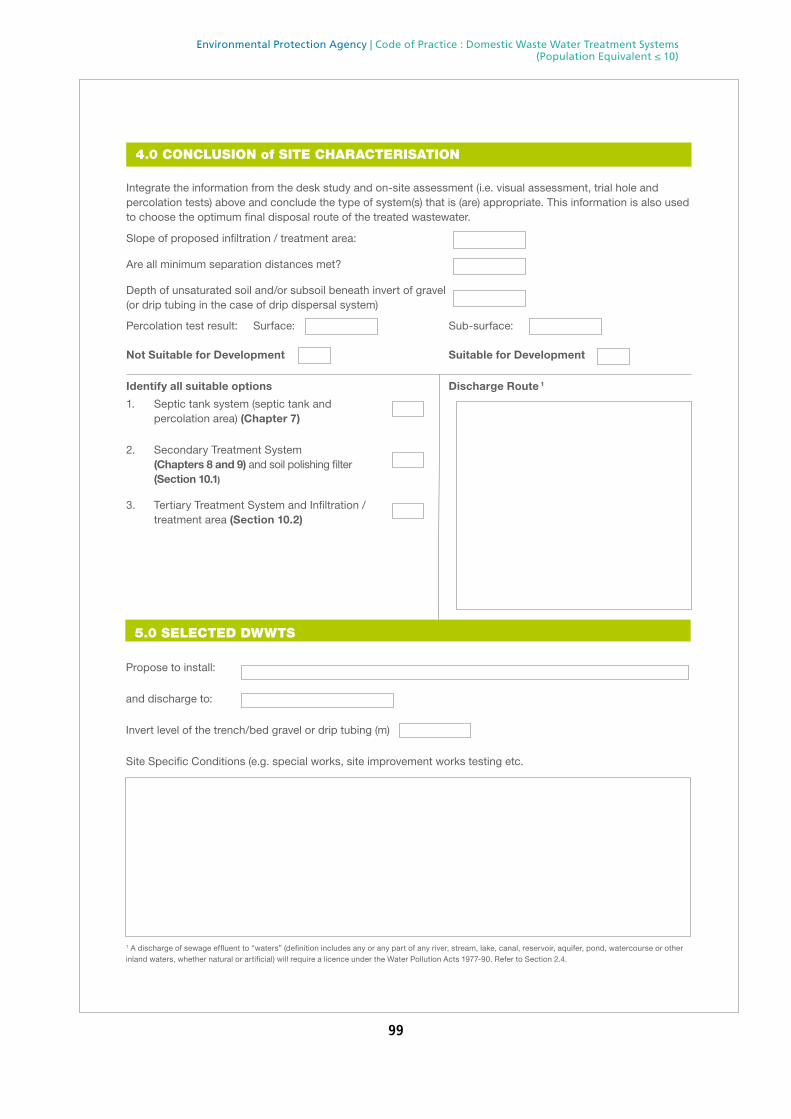
99
Environmental Protection Agency | Code of Practice : Domestic Waste Water Treatment Systems (Population Equivalent ≤ 10)
Integrate the information from the desk study and on-site assessment (i.e. visual assessment, trial hole and percolation tests) above and conclude the type of system(s) that is (are) appropriate. This information is also used to choose the optimum final disposal route of the treated wastewater.
Slope of proposed infiltration / treatment area:
Are all minimum separation distances met?
Depth of unsaturated soil and/or subsoil beneath invert of gravel (or drip tubing in the case of drip dispersal system)
Percolation test result: Surface: Sub-surface:
Not Suitable for Development Suitable for Development
Identify all suitable options Discharge Route 1
1. Septic tank system (septic tank and percolation area) (Chapter 7)
2. Secondary Treatment System (Chapters 8 and 9) and soil polishing filter (Section 10.1)
3. Tertiary Treatment System and Infiltration / treatment area (Section 10.2)
4.0 CONCLUSION of SITE CHARACTERISATION
5.0 SELECTED DWWTS
Propose to install:
and discharge to:
Invert level of the trench/bed gravel or drip tubing (m)
Site Specific Conditions (e.g. special works, site improvement works testing etc.
1 A discharge of sewage effluent to “waters” (definition includes any or any part of any river, stream, lake, canal, reservoir, aquifer, pond, watercourse or other inland waters, whether natural or artificial) will require a licence under the Water Pollution Acts 1977-90. Refer to Section 2.4.

100
Environmental Protection Agency | Code of Practice : Domestic Waste Water Treatment Systems (Population Equivalent ≤ 10)
SYSTEM TYPE: Septic Tank Systems (Chapter 7)
Tank Capacity (m3) Percolation Area Mounded Percolation Area
No. of Trenches No. of Trenches
Length of Trenches (m) Length of Trenches (m)
Invert Level (m) Invert Level (m)
SYSTEM TYPE: Secondary Treatment System (Chapters 8 and 9) and polishing filter (Section 10.1)
Secondary Treatment Systems receiving septic tank effluent Packaged Secondary (Chapter 8) Treatment Systems receiving raw wastewater (Chapter 9)
Media Type Area (m2)* Depth of Filter Invert Level Type
Sand/Soil
Soil Capacity PE
Constructed Wetland Sizing of Primary Compartment Other m3
Polishing Filter*: (Section 10.1) Surface Area (m2)*
Option 1 - Direct Discharge Surface area (m2)
Option 2 - Pumped Discharge Surface area (m2)
DISCHARGE ROUTE:
Groundwater Hydraulic Loading Rate * (l/m2.d) Surface area (m2)
Surface Water ** Discharge Rate (m3/hr)
6.0 TREATMENT SYSTEM DETAILS
* Hydraulic loading rate is determined by the percolation rate of subsoil ** Water Pollution Act discharge licence required
Identify purpose of tertiary treatment
Option 3 - Gravity Discharge Trench length (m)
Option 4 - Low Pressure Pipe Distribution Trench length (m)
Option 5 - Drip Dispersal Surface area (m2)
SYSTEM TYPE: Tertiary Treatment System and infiltration / treatment area (Section 10.2)
Provide performance information demonstrating system will provide required treatment levels
Provide design information

101
Environmental Protection Agency | Code of Practice : Domestic Waste Water Treatment Systems (Population Equivalent ≤ 10)
Company:
Prefix: First Name: Surname:
Address:
Qualifications/Experience:
Date of Report:
Phone: E-mail
Indemnity Insurance Number:
Signature: ________________________________________
7.0 SITE ASSESSOR DETAILS
6.0 TREATMENT SYSTEM DETAILS
QUALITY ASSURANCE:
Installation & Commissioning
On-going Maintenance

102
Environmental Protection Agency | Code of Practice : Domestic Waste Water Treatment Systems (Population Equivalent ≤ 10)
APPENDIX B: PLANTS INDICATIVE OF DRAINAGE CONDITIONSThe following photographs illustrate plants that indicate dry conditions throughout the year (good drainage) and plants that indicate wet conditions throughout the year (poor drainage).
Some of the photographs illustrate the plants in flower; this aspect should be ignored. Plants in flower, or otherwise, do not change their indicator status. Note that alder is a tree.
DRY CONDITIONS
bracken ragwort
WET CONDITIONS
alder iris
rush willow

103
Environmental Protection Agency | Code of Practice : Domestic Waste Water Treatment Systems (Population Equivalent ≤ 10)
APPENDIX C: SUBSOIL CLASSIFICATION FLOW CHART

104
Environmental Protection Agency | Code of Practice : Domestic Waste Water Treatment Systems (Population Equivalent ≤ 10)
Flo
w C
har
t fo
r D
escr
ibin
g S
ub
soils
This
cha
rt is
a g
uide
, bas
ed o
n BS
5930
:199
9, a
nd d
oes
not
repr
esen
t al
l ava
ilabl
e op
tions
, Apr
il 20
08 -
GSI
YES
NO
YES
NO
YES
NO
YES
YES
YES
YES
NO
NO
NO
NO
YES
YES
NO
NO
Rem
ove
boul
ders
and
co
bble
s. D
o th
ey w
eigh
m
ore
than
the
res
t of
the
sa
mpl
e?
A.
Prep
are
hand
sa
mpl
e
App
aren
t co
hesi
on.
Doe
s sa
mpl
e st
ick
toge
ther
whe
n w
et?
B.
C.
Step
s D
, E a
nd F
. Rem
ove
grav
el g
rain
s. U
se t
hrea
d te
sts,
rib
bon
test
s an
d di
lata
ncy
test
s to
diff
eren
tiate
silt
and
cla
y.
(Pro
cedu
res
for
each
tes
t ar
e sh
own
on t
he n
ext
page
).
Are
mos
t pa
rtic
les
> 2
00m
m?
Are
mos
t pa
rtic
les
> 2
mm
?
Thre
adca
nnot
be
form
ed?
AN
D
Ribb
ons
<40
mm
Two
to fi
ve
thre
ads?
AN
D
Ribb
ons
80-1
00m
m
AN
D
Dila
tes
with
di
fficu
lty, o
rdl
iata
ncy
unce
rtai
n?
One
or
two
thre
ads,
or v
aria
ble
one
to t
hree
thre
ads?
AN
D
Ribb
ons
<10
0mm
AN
D
Dila
tant
?
Thre
e or
mor
eth
read
s?
AN
D
Ribb
ons
110m
m
or m
ore
AN
D
Not
dila
tant
?
If un
cert
ain
abou
t di
lata
ncy,
but
hav
e th
ree
or m
ore
thre
ads
and
ribbo
ns o
f 10
0mm
or
mor
eA
ND
Palm
doe
s no
t dr
y ou
t du
ring
hand
te
sts
AN
DO
ily s
heen
on
cut/
smea
red
surf
aces
AN
DSa
mpl
e do
es n
ot
begi
n to
di
sint
egra
te a
fter
se
vera
l min
utes
imm
ersi
on in
wat
er
Seco
nd
ary
Co
nst
itu
ents
NB
: Und
er B
S593
0 de
term
inat
ions
of
seco
ndar
y co
nstit
uent
s ar
e m
ade
usin
g gr
ain
size
dat
a. T
he f
ollo
win
g gu
ides
are
inte
nded
onl
y fo
r in
itial
fiel
d st
udie
s.
Bo
uld
ersm
Co
bb
les
and
Gra
vel
Rem
ove
part
icle
s be
long
ing
to t
he p
rinci
pal s
ubso
il ty
pe a
nd
exam
ine
rem
aind
er o
f sa
mpl
e ac
cord
ing
to C
to
F ab
ove.
NB
: Mor
e th
an 1
con
stitu
ent
can
be n
amed
, if
appr
opria
te, b
ut
the
term
s ‘c
laye
y’ a
nd ‘s
ilty’
are
mut
ually
exc
lusi
ve u
nder
BS
5930
:199
9
San
dC
ohes
ive
sam
ples
/ re
adily
dila
tant
- ‘s
ilty’
Coh
esiv
e sa
mpl
es /
dila
tes
with
diffi
culty
- ‘c
laye
y’G
rave
ls c
omm
on -
‘gra
velly
’N
B: M
ore
than
1 c
onst
ituen
t ca
n be
nam
ed, i
f ap
prop
riate
, but
the
te
rms
‘cla
yey’
and
‘silt
y’ a
re m
utua
lly e
xclu
sive
und
er B
S593
0:19
99.
‘Gra
velly
’ can
be
used
with
eith
er t
erm
.
Silt
, Cla
y an
d S
ilt/C
lay
Grit
ty f
eel a
nd r
apsy
sou
nd -
‘san
dy’
Gra
vels
mor
e th
an a
ppro
xim
atel
y 1/
3 of
tot
al w
eigh
t -
‘gra
velly
’
NB
: Bot
h ‘s
andy
’ and
‘gra
velly
’ can
be
used
, if
appr
opria
te. H
owev
er
the
term
s ‘c
laye
y’ a
nd ‘s
ilty’
are
mut
ually
exc
lusi
ve u
nder
BS
5930
:199
9.
BO
ULD
ER
SC
OB
BLE
SG
RA
VEL
SA
ND
SIL
TC
LAY
SIL
T / C
LAY

105
Environmental Protection Agency | Code of Practice : Domestic Waste Water Treatment Systems (Population Equivalent ≤ 10)
PARTICLE SIZES AS DEFINED IN BS5930:1999
Boulder >200 mm Larger than a soccer ball
Cobble 60–200 mm Smaller than a soccer ball, but larger than a tennis ball
Gravel 2–60 mm Smaller than a tennis ball, but larger than match heads
Sand 0.06–2 mm Smaller than a match head, but larger than flour
Silt 0.002–0.06 mm Smaller than flour (not visible to the naked eye)
Clay <0.002 mm Not visible to the naked eye.
A: Examine Boulders & Cobbles B & C: Preparation of Sample and Apparent Cohesion Test
Test adapted from the British Standards Institution BS 5930:1999 Code of Practice for Site Investigations (1999).
Using a hammer, trowel, or pick, clean off a portion of the trial pit wall.
Examine whether the quantity of boulders/cobbles is dominant over finer material. This will usually be easily done by eye. If unsure, separate boulders/cobbles from finer material in two sample bags and compare weights by hand.
Test taken from the British Standards Institution BS 5930:1999
Code of Practice for Site Investigations (1999).
Collect a hand-sized representative sample from the cleaned-off portion of the trial pit wall.
Remove particles larger than 2 mm, as far as possible.
Crush clumps of subsoil and break down the structure of the sample.
Slowly add water (preferably as a fine spray), mixing and moulding the sample until it is the consistency of putty; it should be pliable but not sticky and shouldn’t leave a film of material on your hands. Can the sample be made pliable at the appropriate moisture content?
If it can, squeeze the sample in your fist – does it stick together?
D: Thread Test E: Ribbon Test
Test adapted from a combination of the American Society of Testing and Materials Designation Standard Practice for Description and Identification of Soils (Visual–manual Procedure) (1984), and the British Standards Institution BS 5930:1999 Code of Practice for Site Investigations (1999).Ensure the sample is of the consistency of putty. This is very important! Add extra water or sample to moisten or dry the sample.Check that no particles greater than 1 or 2 mm occur in the prepared sample.Gently roll a thread 3 mm in diameter across the width of the palm of your hand. Remove excess material.If a thread can be rolled, break it and try to re-roll without adding additional water.Repeat until the thread can no longer be rolled without breaking. Record the total number of threads that were rolled and re-rolled.Repeat the test at least twice per sample. Water can be added before each test repetition, to return the sample to the consistency of putty.
Test adapted from the United States Department of Agriculture Soil Conservation Service Soil Survey Agricultural Handbook 18 (1993).Ensure the sample is of the consistency of putty. This is very important! Add extra water or sample to moisten or dry the sample.Check that no particles greater than 1 or 2 mm occur.Form your moist sample into a large roll in your hand, approximately the width of your thumb.Hold your hand and arm parallel with the ground. Using your thumb, press the sample over your index finger to form a uniform ribbon about thumb-width and 0.5 cm thick. Let this ribbon hang over your index finger and continue to extrude the ribbon between thumb and index finger until it breaks. Be careful not to press your thumb through the ribbon.Measure the total length of the formed ribbon when it breaks (i.e. from tip of thumb to end of ribbon).Repeat this test at least 3 times per sample to obtain an average ribbon value. Water can be added between each repetition, to return the sample to the consistency of putty

106
Environmental Protection Agency | Code of Practice : Domestic Waste Water Treatment Systems (Population Equivalent ≤ 10)
F: Dilatancy Test
Test taken from British Standards Institution BS 5930:1999 Code of Practice for Site Investigations (1999).Wet the sample such that it is slightly more wet (and softer) than for a thread test, but not so wet that free water is visible at the surface.Spread the sample in the palm of one hand, such that no free water is visible at the surface.Using the other hand, jar the sample 5 times by slapping the heel of your hand or the ball of your thumb. Take note of whether water rises to the surface or not, and how quickly it does so.Squeeze the sample, again noting if the water disappears or not, and how quicklyDilatant samples will show clear and rapid emergence of a sheen of water at the surface during shaking, and clear and rapid disappearance from the surface during squeezing. Non dilatant samples will show no discernible sheen.Decide whether your sample has dilatancy. Beginners often find it quite difficult to determine the presence of a sheen, unless it is very obvious. It will become easier once samples with clear dilatancy are observed.
BS5930:1999 Criteria for describing density/compactness (fine subsoils)
BS5930:1999 Criteria for describing discontinuities
Term Field Test Term Mean spacing (mm)
Uncompact Easily moulded or crushed in fingers
Very widely >2000
Compact Can be moulded or crushed by strong finger pressure
Widely 2000–600
Very soft Finger easily pushed up to 25 mm Medium 600–200
Soft Finger pushed up to 10 mm Closely 200–60
Firm Thumb makes impression easily Very closely 60–20
Stiff Can be indented slightly by thumb Extremely closely <20
Very stiff Can be indented by thumb nail Fissured Breaks into blocks along unpolished discontinuities
Hard Can be scratched by thumb nail Sheared Breaks into blocks along polished discontinuities

107
Environmental Protection Agency | Code of Practice : Domestic Waste Water Treatment Systems (Population Equivalent ≤ 10)
APPENDIX D: PERCOLATION TEST PROCEDUREStep 1: Three percolation test holes are dug adjacent to the proposed percolation area, but not in the proposed area.
Each hole should be 300 mm x 300 mm x 400 mm deep2 and the top of the hole should be located as close as possible to the invert of the percolation pipe (or the basal gravel layer in the case of a sand filter with underlying polishing filter), meaning that the base of the hole will be at approximately 950 mm depth if the pipe invert will be at 550 mm (Figure D1). Otherwise the depth of hole should reflect testing the subsoil above the water table or the bedrock in the case of relatively shallow depths of unsaturated soil and/or subsoil.
The exact dimensions of the holes should be noted on the site characterisation form. When initially excavated, the bottom and sides of the hole should be scratched with a knife or wire brush to remove any compacted or smeared soil surfaces and to expose the natural soil surface.
Step 2: The hole should be pre-soaked twice from 4 to 24 hours before the start of the percolation test by carefully pouring clear water into the hole to fill it to the full height of 400 mm. Any soil matrix that falls into the bottom of the test holes during the carrying out of the pre-soakage should be removed prior to refilling. If the water in the hole fully percolates in less than 10 minutes twice, proceed to step 3 immediately; otherwise, step 3 commences the next day.
Figure: D1
2 Change in the size of hole will affect the validity of the results.
Base of thePercolation Trench
UnsaturatedUndisturbed
Subsoil
Ground Level
GeotextileMembrane
300mm minimum
850mm minimum
1,200mm or 2,000mm minimum above water table and/or bedrockdepending on the groundwaterprotection response (see Table 6.3)
300mm
100mm
150mm
PercolationPipe
500mm
Gravel
300mm
Proposed Invertof Percolation Pipe
Water level
T Test Hole
400mm
SubsurfacePercolationTest Hole
Ground Level
300mm
400mm
SurfacePercolationTest Hole
Water level
100mm

108
Environmental Protection Agency | Code of Practice : Domestic Waste Water Treatment Systems (Population Equivalent ≤ 10)
Step 3: After the hole has been pre-soaked (step 2), it is filled once again to the full height of 400 mm. The time that the hole is filled is noted. The water should be allowed to drop to 300 mm and the time noted.
Percolation test hole
1 2 3
Fill no. Start time (at
400 mm)
Finish time (at
300 mm)
Δt (min)
Start time (at
400 mm)
Finish time (at
300 mm)
Δt (min)
Start time (at
400 mm)
Finish time (at
300 mm)
Δt (min)
1
There are three possible scenarios after this stage of the test, namely:
Scenario 1: If the initial drop from 400 mm to 300 mm is greater than eight hours this means the percolation value will be greater than 120. There is no requirement to complete the test and the trial hole location is not suitable for discharge to ground at the level of that percolation test, as stated in Section 6.3 of I.S. CEN/TR 12566-2:2005.
Scenario 2: If the initial drop from 400 mm to 300 mm in all or any of the holes is less than or equal to 210 minutes then the test should be continued for that hole using the standard method given in step 4.
Scenario 3: If initial drop from 400 mm to 300 mm in all or any of the holes is greater than 210 minutes then skip step 4 and continue using the modified method given in Step 5.

109
Environmental Protection Agency | Code of Practice : Domestic Waste Water Treatment Systems (Population Equivalent ≤ 10)
Step
4:
Con
tinue
to
let
the
leve
l of
wat
er d
rop
to 2
00 m
m,
reco
rdin
g th
e tim
es a
t 30
0 m
m a
nd 2
00 m
m.
The
time
to d
rop
this
100
mm
in d
epth
is
calc
ulat
ed (D
t). T
he h
ole
is t
hen
refil
led
agai
n to
the
300
mm
leve
l and
the
tim
e fo
r th
e w
ater
leve
l to
drop
to
200
mm
is r
ecor
ded
and
Dt
is c
alcu
late
d (T
able
D1)
. The
hol
e sh
ould
the
n be
ref
illed
onc
e m
ore
and
the
time
is r
ecor
ded
for
the
wat
er le
vel t
o dr
op t
o 20
0 m
m a
nd D
t is
cal
cula
ted.
Thi
s m
eans
th
at t
hree
tes
ts a
re c
arrie
d ou
t in
the
hol
e an
d th
e ho
le is
ref
illed
tw
ice.
The
ave
rage
Dt
is c
alcu
late
d fo
r th
e ho
le. T
he a
vera
ge D
t is
div
ided
by
4, g
ivin
g th
e av
erag
e tim
e fo
r th
e w
ater
leve
l to
fall
25 m
m,
whi
ch g
ives
a p
erco
latio
n va
lue
for
that
hol
e. T
his
proc
edur
e is
rep
eate
d in
eac
h of
the
tes
t ho
les.
Th
e pe
rcol
atio
n va
lues
for
eac
h ho
le a
re t
hen
adde
d to
geth
er a
nd d
ivid
ed b
y 3
to g
ive
the
over
all p
erco
latio
n va
lue
for
the
site
.
Tab
le D
1: S
tand
ard
Met
hod
STEP
4: S
tan
dar
d m
eth
od
(w
her
e ti
me 10
0 ≤2
10 m
inu
tes)
Perc
olat
ion
test
hol
e1
23
Fill
no.
Star
t tim
e (a
t 40
0 m
m)
Fini
sh t
ime
(at
300
mm
)Δt
(m
in)
Star
t tim
e (a
t 40
0 m
m)
Fini
sh t
ime
(at
300
mm
)
Δt (m
in)
Star
t tim
e (a
t 40
0 m
m)
Fini
sh t
ime
(at
300
mm
)
Δt (m
in)
Fini
sh
time
(at
200
mm
)
Δt (m
in)
1 2 3 Ave
rage
Δt
valu
e
Ave
rage
Δt/4
= [h
ole
no.1
] ___
____
__(t 1)
Ave
rage
Δt/
4 =
[hol
e no
.2] _
____
___(
t 2)A
vera
ge Δ
t/4
= [h
ole
no.3
] ___
__(t
3)
Perc
olat
ion
valu
e* =
(t1
+ t
2 +
t3)
/3 =
___
____
(min
/25
mm
)Re
sult
of t
est:
pe
rcol
atio
n va
lue
=C
OM
MEN
TS:

110
Environmental Protection Agency | Code of Practice : Domestic Waste Water Treatment Systems (Population Equivalent ≤ 10)
Step
5:
Con
tinue
to
let
the
leve
l of
wat
er d
rop
to 1
00 m
m,
reco
rdin
g th
e tim
e at
250
mm
, 20
0 m
m,
150
mm
and
100
mm
(Tm
) (T
able
D2)
. Th
e tim
e fa
ctor
(Tf
) is
the
n di
vide
d by
the
tim
e fo
r ea
ch d
rop
to g
ive
a m
odifi
ed h
ydra
ulic
con
duct
ivity
(K
fs).
The
equi
vale
nt p
erco
latio
n va
lue
is c
alcu
late
d by
di
vidi
ng 4
.45
by th
e K
fs. T
ake
the
aver
age
of th
e fo
ur v
alue
s fr
om 3
00 to
100
mm
. Thi
s is
repe
ated
for e
ach
rele
vant
per
cola
tion
hole
and
the
perc
olat
ion
valu
es f
or e
ach
hole
are
add
ed t
oget
her
and
divi
ded
by 3
to
give
the
ove
rall
perc
olat
ion
valu
e fo
r th
e si
te.
Tab
le D
2: M
odifi
ed M
etho
d
STEP
5: M
od
ifie
d m
eth
od
(w
her
e ti
me 10
0 >
210
min
ute
s)
Perc
ola
tio
n
test
ho
le1
23
Fall
of w
ater
in
hol
e (m
m)
Tim
e fa
ctor
=
Tf
Tim
e of
fa
ll (m
in) =
T m
Kfs =
Tf/T
mT-
valu
e =
4.
45/K
fs
Tim
e fa
ctor
=
Tf
Tim
e of
fal
l (m
in) =
T m
Kfs =
Tf/T
mT-
valu
e =
4.
45/K
fs
Tim
e fa
ctor
=
Tf
Tim
e of
fa
ll (m
in) =
T m
Kfs =
Tf/
T m
T-va
lue
=
4.45
/Kfs
300
–250
8.1
8.1
8.1
250
–200
9.7
9.7
9.7
200
–150
11.9
11.9
11.9
150
–100
14.1
14.1
14.1
Ave
rag
e p
erco
lati
on
va
lue
Perc
ola
tio
n v
alu
e h
ole
1 =
(t 1)
Perc
ola
tio
n v
alu
e h
ole
2
= (
t 2)Pe
rco
lati
on
val
ue
ho
le 3
= (
t 3)
Perc
olat
ion
valu
e* =
(t1
+ t
2 +
t3)
/3 =
___
____
(min
/25
mm
)
Resu
lt of
tes
t:
perc
olat
ion
valu
e =
CO
MM
ENTS
:

111
Environmental Protection Agency | Code of Practice : Domestic Waste Water Treatment Systems (Population Equivalent ≤ 10)
APPENDIX E: GROUNDWATER PROTECTION RESPONSES
BACKGROUNDThe primary responsibility for groundwater protection rests with any person who is carrying on an activity that poses a threat to groundwater. Groundwater in Ireland is protected under European Community and national legislation. Local authorities and the EPA have responsibility for enforcing this legislation. Geological Survey Ireland (GSI) in conjunction with the Department of Environment and Local Government (DELG) and the EPA issued guidelines on the preparation of groundwater protection schemes (GWPSs) to assist the statutory authorities and others to meet their responsibility to protect groundwater (DELG/EPA/GSI, 1999). A GWPS incorporates land surface zoning and groundwater protection responses (GWPRs).
The GWPRs outline acceptable DWWTSs in each groundwater protection zone (as described in DELG/EPA/GSI, 1999) and recommend conditions and/or investigations depending on the groundwater vulnerability, the value of the groundwater resource and the contaminant loading. It will be noted that these responses relate to discharges to groundwater. Less stringent responses may be appropriate for discharges to surface waters.
When choosing the location and type of DWWTSs, developers should have regard to any nearby groundwater source, the groundwater as a resource and the vulnerability of the underlying groundwater. The groundwater protection responses in this guidance combine these factors to produce a response matrix.
The objectives of these groundwater protection responses are:
\ to reduce the risk of pollutants reaching drinking water supplies;
\ to reduce the risk of pollution of aquifers;
\ to minimise pollution of domestic wells;
\ to provide advice where it is proposed to locate domestic wells in the vicinity of existing waste water treatment systems and vice versa.
\ The risk from on-site waste water treatment systems is mainly influenced by:
\ proximity to a groundwater source;
\ groundwater vulnerability;
\ the value of the groundwater resource;
\ the height of the water table;
\ the groundwater flow direction;
\ the type of on-site system and the quality of the final effluent.
The use of these groundwater protection responses allows decisions to be made on the acceptability or otherwise of DWWTSs from a hydrogeological point of view.
These groundwater protection responses should be read in conjunction with GWPSs (DELG/EPA/GSI, 1999). Other published responses in this series are Groundwater Protection Responses for Landfills and Groundwater Protection Response to the Landspreading of Organic Wastes.

112
Environmental Protection Agency | Code of Practice : Domestic Waste Water Treatment Systems (Population Equivalent ≤ 10)
Groundwater Protection Response Matrix for Single House DWWTssThe reader is referred to the full text in Groundwater Protection Schemes (DELG/EPA/GSI, 1999) for an explanation of the role of GWPRs in a GWPS.
A risk assessment approach is taken in the development of this response matrix. A precautionary approach is taken because of the variability of Irish subsoils and bedrock and the possibility that the DWWTS may not function properly at all times. Where there is a high density of dwellings in the vicinity of public, group scheme or industrial water supply sources, more restrictive conditions may be required or the development may need to be refused. The density of dwellings and associated DWWTSs may impact on the groundwater because of the cumulative loading, particularly of nitrate. This should be taken into account especially where the vulnerability of the groundwater is extreme or high (see Appendix F).
The potential suitability of a site for the development of a DWWTS is assessed using the methodology outlined in Chapter 6. The methodology includes a desk study and on-site assessment (visual, trial hole test and percolation tests). The GWPRs set out in Table E1 below should be used during the desk study assessment of a site to give an early indication of its suitability for a DWWTS. Information from the on-site assessment should be used to confirm or modify the response. Where the response has been modified in such a manner, the detail of this should be included in the ‘Comments’ box at the end of the trial hole assessment on the Site Characterisation Form.
The appropriate response to the risk of groundwater contamination from a DWWTS is given by the assigned response category (R) appropriate to each protection zone.
Table E1: Response matrix for DWWTSs
Vulnerability rating
Source protection
areaa
Resource protection areaAquifer category
Regionally imp. Locally imp. Poor aquifers
Inner (SI)
Outer (SO)
Rk/Lk Rf/Rg Lm/Lg Ll Pl Pu
Extreme (E) R32 R31 R22 R22 R21 R21 R21 R21
High (H) R24 R23 R21 R1 R1 R1 R1 R1
Moderate (M) R24 R23 R1 R1 R1 R1 R1 R1
Low (L) R24 R1 R1 R1 R1 R1 R1 R1
a For public, group scheme or industrial water supply sources where protection zones have not been delineated, the arbitrary distances given in DELG/EPA/GSI (1999) of 300 m for the inner protection area (SI) and 1000 m for the outer protection area (SO) should be used as a guide up-gradient of the source.

113
Environmental Protection Agency | Code of Practice : Domestic Waste Water Treatment Systems (Population Equivalent ≤ 10)
R1 Acceptable subject to normal good practice (i.e. system selection, construction, operation and maintenance in accordance with this CoP)
R21
Acceptable subject to normal good practice. Where domestic water supplies are located Nearby, particular attention should be given to the depth of subsoil over bedrock such that the minimum depths required in Chapter 6 are met and the likelihood of microbial pollution is minimised
R22 Acceptable subject to normal good practice and the following additional condition:
1. There is a minimum thickness of 2 m unsaturated soil/subsoil beneath the invert of the percolation trench of a septic tank system
OR
2. A secondary treatment system as described in Chapters 8 and 9 is installed, with a minimum thickness of 0.3 m unsaturated soil/subsoil with percolation values from 3 to 75 (in addition to the polishing filter, which should be a minimum depth of 0.9 m), beneath the invert of the polishing filter (i.e. 1.2 m in total for a soil polishing filter).
R23 Acceptable subject to normal good practice, condition 1 and 2 above and the following additional condition:
3. The authority should be satisfied that, on the evidence of the groundwater quality of the source and the number of existing houses, the accumulation of significant nitrate and/or microbiological contamination is unlikely.
R24 Acceptable subject to normal good practice, conditions 1, 2 and 3 above and the following additional condition:
4. No on-site treatment system should be located within 60 m of the public, group scheme or industrial water supply source.
R31 Not generally acceptable, unless:
A septic tank system as described in Chapter 7 is installed with a minimum thickness of 2 m unsaturated soil/subsoil beneath the invert of the percolation trench (i.e. an increase of 0.8 m from the requirements in Chapter 6);
OR
A secondary treatment system as described in Chapters 8 and 9 is installed with a minimum thickness of 0.3 m unsaturated soil/subsoil with percolation values from 3 to 75 (in addition to the polishing filter, which should be a minimum depth of 0.9 m), beneath the invert of the polishing filter (i.e. 1.2 m in total for a soil polishing filter).
and subject to the following conditions:
1. The authority should be satisfied that, on the evidence of the groundwater quality of the source and the number of existing houses, the accumulation of significant nitrate and/or microbiological contamination is unlikely.
2. No on-site treatment system should be located within 60 m of the public, group scheme or industrial water supply source.
3. A management and maintenance agreement is completed with the systems supplier.

114
Environmental Protection Agency | Code of Practice : Domestic Waste Water Treatment Systems (Population Equivalent ≤ 10)
R32 Not generally acceptable unless:
A secondary treatment system is installed with a minimum thickness of 0.9 m unsaturated soil/subsoil with percolation values from 3 to 75 (in addition to the polishing filter, which should be a minimum depth of 0.9 m) beneath the invert of the polishing filter (i.e. 1.8 m in total for a soil polishing filter).
and subject to the following conditions:
1. The authority should be satisfied that, on the evidence of the groundwater quality of the source and the number of existing houses, the accumulation of significant nitrate and/or microbiological contamination is unlikely.
2. No on-site treatment system should be located within 60 m of the public, group scheme or industrial water supply source.
3. A management and maintenance agreement is completed with the systems supplier.
The responses above assume that there is no significant groundwater contamination in the area. Should contamination by pathogenic organisms or nitrate (or other contaminants) be a problem in any particular area, more restrictive responses may be necessary. Where nitrate levels are known to be high or nitrate-loading analysis indicates a potential problem, consideration should be given to the use of DWWTSs that include a de-nitrification unit. Monitoring carried out by the local authority will assist in determining whether or not a variation in any of these responses is required.
Sites are not suitable for discharge of effluent to ground for very-low-permeability soils and subsoils (where the percolation values are >120).
Additional Requirements for the Location of On-site Treatment Systems Adjacent to Receptors at Risk, such as Wells and Karst FeaturesTable E1 above outlines responses for different hydrogeological situations, which may restrict the type of DWWTSs, and should be satisfied in the first instance. Once a response has been determined for a site, the next step is to manage the risk posed to the features identified during the desk study and on-site assessment. These features include water supply wells and springs (public and domestic), and karst features that enable the soils and subsoil to be bypassed (e.g. swallow holes, collapse features).
Table E2 below provides recommended distances between receptors (see also Figure E1) and percolation area or polishing filters, in order to protect groundwater. These distances depend on the thickness and permeability of subsoil. The depths and distances given in this table are based on the concepts of ‘risk assessment’ and ‘risk management’, and take account, as far as practicable, of the uncertainties associated with hydrogeological conditions in Ireland. Use of the depths and distances in this table does not guarantee that pollution will not be caused; rather, it will reduce the risk of significant pollution occurring.

115
Environmental Protection Agency | Code of Practice : Domestic Waste Water Treatment Systems (Population Equivalent ≤ 10)
Table E2: Recommended Minimum Distance between a Receptor and a Percolation Area or Polishing Filter
Percolation valuea
Type of soil/subsoilb
Depth of soil/subsoil (m) above bedrock
(see notes 1, 2, 3, 4 and 6)
Minimum distance (m) from receptor to percolation area or polishing filtere
Public/group water supply
abstraction points/wells
Karst feature
Down-gradient domestic
well or flow direction is unknown
(see note 5)
Domestic well
alongside (no
gradient)
Up-gradient domestic
well
>30 CLAY; sandy CLAY (e.g. clayey till); SILT/CLAY, sandy SILT/CLAY
1.2
>3.0
60 15 40
30
25 15
10–30 SILT; sandy SILT; clayey SAND; clayey, silty GRAVEL (e.g. sandy till)
1.2
>8.0
60 15 45
30
25 15
<10 SAND; GRAVEL; silty SAND
2.0c
2.0d
>8.0d
60 15 60
40
30
25 15
a) The percolation value (expressed as min/25 mm) is the time taken for the water level to drop a specified distance in a percolation test hole.
b) BS 5930 descriptions.
c) Water table 1.2–2.0 m.
d) Water table > 2.0 m.
e) The distance from the percolation area or polishing filter means the distance from the periphery of the percolation area or polishing filter and not the centre.
Notes:
1. Depths are measured from the invert level of the percolation trench.
2. Depths and distances can be related by interpolation, e.g. when the thickness of sandy CLAY is 1.2 m, the minimum recommended distance from the well to percolation area is 40 m; when the thickness is 3.0 m, the distance is 30 m; distances for intermediate depths can be approximated by interpolation.
3. When bedrock is shallow (<2 m below the invert of the trench), greater distances may be necessary when there is evidence of the presence of PFPs (e.g. cracks, roots) in the subsoil.
4. When the minimum subsoil thicknesses are less than those given above, site improvements and systems other than systems as described in Chapters 8 and 9 may be used to reduce the likelihood of contamination.
5. If effluent and bacteria enter bedrock rapidly (within 1–2 days), the distances given may not be adequate when the percolation area is in the ZOC of a well. Further site-specific evaluation is necessary.
6. When bedrock is known to be karstified or highly fractured, greater depths of subsoil may be advisable to minimise the likelihood of contamination.

116
Environmental Protection Agency | Code of Practice : Domestic Waste Water Treatment Systems (Population Equivalent ≤ 10)
When a DWWTS is in the ZOC of a well, the likelihood of contamination and the threat to human health depend largely on five factors:
1. the thickness and permeability of subsoil beneath the invert of the percolation trench;
2. the permeability of the bedrock, where the well is tapping the bedrock;
3. the distance between the well or spring and the on-site system;
4. the groundwater flow direction;
5. the level of treatment of effluent.
Figure E1: Relative Location of wells
Groundwater flow direction
Groundwater flow direction
Dwelling
Tank/Plant
7m (min)
Percolation Area
Down-gradient well
Alongsidewell
Distributiondevice
Up-gradientwell
Groundwater flow direction
OnSite System

AN GHNÍOMHAIREACHT UM CHAOMHNÚ COMHSHAOILTá an GCC freagrach as an gcomhshaol a chosaint agus a fheabhsú, mar shócmhainn luachmhar do mhuintir na hÉireann. Táimid tiomanta do dhaoine agus don chomhshaol a chosaint ar thionchar díobhálach na radaíochta agus an truaillithe.
Is féidir obair na Gníomhaireachta a roinnt ina trí phríomhréimse:Rialáil: Rialáil agus córais chomhlíonta comhshaoil éifeachtacha a chur i bhfeidhm, chun dea-thorthaí comhshaoil a bhaint amach agus díriú orthu siúd nach mbíonn ag cloí leo.
Eolas: Sonraí, eolas agus measúnú ardchaighdeáin, spriocdhírithe agus tráthúil a chur ar fáil i leith an chomhshaoil chun bonn eolais a chur faoin gcinnteoireacht.
Abhcóideacht: Ag obair le daoine eile ar son timpeallachta glaine, táirgiúla agus dea-chosanta agus ar son cleachtas inbhuanaithe i dtaobh an chomhshaoil.
I measc ár gcuid freagrachtaí tá:
Ceadúnú• Gníomhaíochtaí tionscail, dramhaíola agus stórála peitril ar scála
mór;
• Sceitheadh fuíolluisce uirbigh;
• Úsáid shrianta agus scaoileadh rialaithe Orgánach Géinmhodhnaithe;
• Foinsí radaíochta ianúcháin;
• Astaíochtaí gás ceaptha teasa ó thionscal agus ón eitlíocht trí Scéim an AE um Thrádáil Astaíochtaí.
Forfheidhmiú Náisiúnta i leith Cúrsaí Comhshaoil• Iniúchadh agus cigireacht ar shaoráidí a bhfuil ceadúnas acu ón
GCC;
• Cur i bhfeidhm an dea-chleachtais a stiúradh i ngníomhaíochtaí agus i saoráidí rialáilte;
• Maoirseacht a dhéanamh ar fhreagrachtaí an údaráis áitiúil as cosaint an chomhshaoil;
• Caighdeán an uisce óil phoiblí a rialáil agus údaruithe um sceitheadh fuíolluisce uirbigh a fhorfheidhmiú
• Caighdeán an uisce óil phoiblí agus phríobháidigh a mheasúnú agus tuairisciú air;
• Comhordú a dhéanamh ar líonra d'eagraíochtaí seirbhíse poiblí chun tacú le gníomhú i gcoinne coireachta comhshaoil;
• An dlí a chur orthu siúd a bhriseann dlí an chomhshaoil agus a
dhéanann dochar don chomhshaol.
Bainistíocht Dramhaíola agus Ceimiceáin sa Chomhshaol• Rialacháin dramhaíola a chur i bhfeidhm agus a fhorfheidhmiú
lena n-áirítear saincheisteanna forfheidhmithe náisiúnta;
• Staitisticí dramhaíola náisiúnta a ullmhú agus a fhoilsiú chomh maith leis an bPlean Náisiúnta um Bainistíocht Dramhaíola Guaisí;
• An Clár Náisiúnta um Chosc Dramhaíola a fhorbairt agus a chur i bhfeidhm;
• Reachtaíocht ar rialú ceimiceán sa timpeallacht a chur i bhfeidhm agus tuairisciú ar an reachtaíocht sin.
Bainistíocht Uisce• Plé le struchtúir náisiúnta agus réigiúnacha rialachais agus
oibriúcháin chun an Chreat-treoir Uisce a chur i bhfeidhm;
• Monatóireacht, measúnú agus tuairisciú a dhéanamh ar chaighdeán aibhneacha, lochanna, uiscí idirchreasa agus cósta, uiscí snámha agus screamhuisce chomh maith le tomhas ar leibhéil uisce agus sreabhadh abhann.
Eolaíocht Aeráide & Athrú Aeráide• Fardail agus réamh-mheastacháin a fhoilsiú um astaíochtaí gás
ceaptha teasa na hÉireann;
• Rúnaíocht a chur ar fáil don Chomhairle Chomhairleach ar Athrú Aeráide agus tacaíocht a thabhairt don Idirphlé Náisiúnta ar Ghníomhú ar son na hAeráide;
• Tacú le gníomhaíochtaí forbartha Náisiúnta, AE agus NA um
Eolaíocht agus Beartas Aeráide.
Monatóireacht & Measúnú ar an gComhshaol• Córais náisiúnta um monatóireacht an chomhshaoil a cheapadh
agus a chur i bhfeidhm: teicneolaíocht, bainistíocht sonraí, anailís agus réamhaisnéisiú;
• Tuairiscí ar Staid Thimpeallacht na hÉireann agus ar Tháscairí a chur ar fáil;
• Monatóireacht a dhéanamh ar chaighdeán an aeir agus Treoir an AE i leith Aeir Ghlain don Eoraip a chur i bhfeidhm chomh maith leis an gCoinbhinsiún ar Aerthruailliú Fadraoin Trasteorann, agus an Treoir i leith na Teorann Náisiúnta Astaíochtaí;
• Maoirseacht a dhéanamh ar chur i bhfeidhm na Treorach i leith Torainn Timpeallachta;
• Measúnú a dhéanamh ar thionchar pleananna agus clár beartaithe ar chomhshaol na hÉireann.
Taighde agus Forbairt Comhshaoil• Comhordú a dhéanamh ar ghníomhaíochtaí taighde comhshaoil
agus iad a mhaoiniú chun brú a aithint, bonn eolais a chur faoin mbeartas agus réitigh a chur ar fáil;
• Comhoibriú le gníomhaíocht náisiúnta agus AE um thaighde comhshaoil.
Cosaint Raideolaíoch• Monatóireacht a dhéanamh ar leibhéil radaíochta agus
nochtadh an phobail do radaíocht ianúcháin agus do réimsí leictreamaighnéadacha a mheas;
• Cabhrú le pleananna náisiúnta a fhorbairt le haghaidh éigeandálaí ag eascairt as taismí núicléacha;
• Monatóireacht a dhéanamh ar fhorbairtí thar lear a bhaineann le saoráidí núicléacha agus leis an tsábháilteacht raideolaíochta;
• Sainseirbhísí um chosaint ar an radaíocht a sholáthar, nó maoirsiú a dhéanamh ar sholáthar na seirbhísí sin.
Treoir, Ardú Feasachta agus Faisnéis Inrochtana• Tuairisciú, comhairle agus treoir neamhspleách, fianaise-
bhunaithe a chur ar fáil don Rialtas, don tionscal agus don phobal ar ábhair maidir le cosaint comhshaoil agus raideolaíoch;
• An nasc idir sláinte agus folláine, an geilleagar agus timpeallacht ghlan a chur chun cinn;
• Feasacht comhshaoil a chur chun cinn lena n-áirítear tacú le hiompraíocht um éifeachtúlacht acmhainní agus aistriú aeráide;
• Tástáil radóin a chur chun cinn i dtithe agus in ionaid oibre agus feabhsúchán a mholadh áit is gá.
Comhpháirtíocht agus líonrú• Oibriú le gníomhaireachtaí idirnáisiúnta agus náisiúnta, údaráis
réigiúnacha agus áitiúla, eagraíochtaí neamhrialtais, comhlachtaí ionadaíocha agus ranna rialtais chun cosaint chomhshaoil agus raideolaíoch a chur ar fáil, chomh maith le taighde, comhordú agus cinnteoireacht bunaithe ar an eolaíocht.
Bainistíocht agus struchtúr na Gníomhaireachta um Chaomhnú ComhshaoilTá an GCC á bainistiú ag Bord lánaimseartha, ar a bhfuil Ard-Stiúrthóir agus cúigear Stiúrthóir. Déantar an obair ar fud cúig cinn d’Oifigí:
• An Oifig um Inbhunaitheacht i leith Cúrsaí Comhshaoil
• An Oifig Forfheidhmithe i leith Cúrsaí Comhshaoil
• An Oifig um Fhianaise agus Measúnú
• An Oifig um Chosaint ar Radaíocht agus Monatóireacht Comhshaoil
• An Oifig Cumarsáide agus Seirbhísí Corparáideacha
Tugann coistí comhairleacha cabhair don Ghníomhaireacht agus tagann siad le chéile go rialta le plé a dhéanamh ar ábhair imní agus le comhairle a chur ar an mBord.

Printed on environmentally friendly paper stock
Headquarters
PO Box 3000, Johnstown Castle Estate County Wexford, Ireland
T: +353 53 916 0600 F: +353 53 916 0699 E: [email protected] W: www.epa.ie LoCall: 1890 33 55 99
Regional Inspectorate McCumiskey House, Richview, Clonskeagh Road, Dublin 14, Ireland
T: +353 1 268 0100 F: +353 1 268 0199
Regional Inspectorate Inniscarra, County Cork, Ireland
T: +353 21 487 5540 F: +353 21 487 5545
Regional Inspectorate Seville Lodge, Callan Road, Kilkenny, Ireland
T +353 56 779 6700 F +353 56 779 6798
Regional Inspectorate John Moore Road, Castlebar County Mayo, Ireland
T +353 94 904 8400 F +353 94 902 1934
Regional Inspectorate The Glen, Monaghan, Ireland
T +353 47 77600 F +353 47 84987
Regional Offices
The Civic Centre Church St., Athlone Co. Westmeath, Ireland T +353 906 475722
Room 3, Raheen Conference Centre, Pearse House, Pearse Road Raheen Business Park, Limerick, Ireland T +353 61 224764