the flower medial column fusion plate - flower ortho€¦ · purchase while avoiding vital...
TRANSCRIPT

The Flower Medial ColumnFusion Plate
PROCEDURE GUIDE
www.flowerortho.com

INDICATIONS FOR USE:The Flower Small and Medium Implants set is intended for use for internal fixation of fractures and reconstruction of bones, including the scapula,olecranon, humerus, radius, ulna, pelvis, distal tibia, fibula, hand and foot in adults and for use in long bones in adolescents (12-21) in whom thegrowth plates have fused. Examples of these internal fixations and reconstructions include compression fractures, intra-articular and extra-articularfractures, displaced fractures, osteotomies, non-unions and mal-unions. This system can be used for palmar, ventral, dorsal and orthogonal application. The Flower Orthopedics Bone Screw set is intended to be used for the fixation of bone structures, fusion of joints of bone reconstruction.
2 The Flower Medial Column Fusion Plate Procedure Guide
The Flower Foot & Ankle Application
NC FUSION PLATE 2-HOLECOMPRESSION
PLATE
TMT FUSION PLATE
6-HOLE STRAIGHT PLATE
COMPRESSION Y-PLATE
COMPRESSION T-PLATE,OBLIQUE
LAPIDUS FUSION PLATE
MTP FUSION PLATE
AKIN PLATE

The Flower Medial Column Plate Fusion Plate createsa robust construct for flatfoot reconstructions,anatomically contoured to best fit patient anatomyand accommodate the NC and first TMT joints.
The Flower Medial Column Plate is recommended tobe used in combination with 4.0mm cannulatedpartially threaded screws across each joint tomaximize compression and produce the most stableconstruct. Plating screws uniquely are positioned toavoid the interfragmentary screws.
Screw holes are positioned to maximize bonepurchase while avoiding vital structures andproviding market-leading fixation in the FlowerMedial Column Fusion Plate. Each joint can beindividually compressed, improving anatomicalignment.
The Flower Medial Column Fusion Plate Procedure Guide 3
The Flower Medial Column Fusion Plate – Design Features
The Flower Medial Column Fusion Plate – Product Rationale
CONSTRUCT FEATURES SURGICAL BENEFIT
Anatomically Based Fixation Screws are targeted to areas of greatest bone purchase, and avoid adjacent structures
Plate positioning on bone facilitates faster andAnatomic Plate Design better anatomic alignment, as well as varied
patient anatomy
Each joint is compressed independentlySegmental Compression through the compression slots, providing
enhanced likelihood for fusion
Plate accepts 2.7mm,3.0mm,3.5mm & 4.0mm Multiple screw options for anatomic varianceVariable Angle Screws strong fixation and inter-operative ease of use
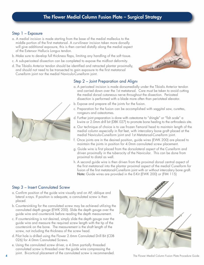
Step 1 – Exposure a. A medial incision is made starting from the base of the medial malleolus to themiddle portion of the first metatarsal. A curvilinear incision taken more dorsallywill give additional exposure, this is then carried distally along the medial aspectof the Extensor Hallucis Longus tendon.
b. Make sure to develop full thickness flaps, limiting any handling of the soft tissue. c. A sub-periosteal dissection can be completed to expose the midfoot deformity.d. The Tibialis Anterior tendon should be identified and retracted plantar proximally,and should not need to be transected to gain exposure to the first metatarsalCuneiform joint nor the medial Naviculo-Cuneiform joint.
4 The Flower Medial Column Fusion Plate Procedure Guide
Step 2 – Joint Preparation and Alignment a. A periosteal incision is made dorsomedially under the Tibialis Anterior tendonand carried down over the 1st metatarsal. Care must be taken to avoid cuttingthe medial dorsal cutaneous nerve throughout the dissection. Periostealdissection is performed with a blade more often than periotsteal elevator.
b. Expose and prepare all the joints for the fusion.c. Preparation for the fusion can be accomplished with saggital saw, curettes,rongeurs and osteotomes.
d. Further joint preparation is done with osteotome to “shingle” or “fish scale” a k-wire or 2.0mm drill bit (DBK 027) to promote bone healing to the arthrodesis site.
e. Our technique of choice is to use frozen Femoral head to maintain length of themedial column especially in flat feet, with intercalary bone graft placed at themedial Naviculo-Cuneiform joint and 1st Metatarsal-Cuneiform joint.
f. Once joints are in the desired position, guide wires (EWK 200) are placed tomaintain the joints in position for 4.0mm cannulated screw placement.
g. Guide wire is first placed from the dorsolateral aspect of the Cuneiform anddriven proximally in the tuberocity of the Navicular. This can be done fromproximal to distal as well.
h. A second guide wire is then driven from the proximal dorsal central aspect ofthe first metatarsal into the plantar proximal aspect of the medial Cuneiform forfusion of the first metatarsal-Cuneiform joint with or without intercalary bone graft.Note: Guide wires are provided in the E-Kit (EWK 200) or (FIM 115)
The Flower Medial Column Fusion Plate – Surgical Strategy
Step 3 – Insert Cannulated Screwa. Confirm position of the guide wire visually and on AP, oblique andlateral x-rays. If position is adequate, a cannulated screw is thenplaced.
b. Countersinking for the cannulated screw may be achieved utilizing thecannulated depth gauge (EWK 200). Slide the depth gauge over theguide wire and countersink before reading the depth measurement.
c. If countersinking is not desired, simply slide the depth gauge over theguide wire and measure the required screw length with the tip of thecountersink on the bone. The measurement is the shaft length of thescrew, not including the thickness of the screw head.
d. Pilot hole is drilled using the Flower 2.6mm Cannulated Drill Bit (CDB026) for 4.0mm Cannulated Screws.
e. Using the cannulated screw driver, a 4.0mm partially threadedcannulated screw is threaded over the guide wire compressing thejoint. Bi-cortical placement of the cannulated screw is recommended.

The Flower Medial Column Fusion Plate Procedure Guide 5
Step 4 – Provisional Fixation Align the plate and insert provisional fixation a. Align the plate on the Navicular, 1st Cuneiform and 1st Metatarsal bone.
Tip: There are a few visual markers to aid in plate positioning. The verticalholes on the proximal end of the plate are placed at the mid portion of thenavicular bone, and the compression slots should align with the cuneiformand metatarsal, respectively.
b. If bending the plate is required, plate benders (FIS 234) can be used. c. Once the plate is in an adequate position, place olive wires in desiredposition to temporarily hold the plate in place on the bone. Tip: If placing an olive wire in the slot, place in the distal end of the slot sonot to interfere with the compression screw later.
The Flower Medial Column Fusion Plate – Surgical Strategy
Step 6 – Screw Measurement and Insertion a. Extend the hook probe out of the depth gauge far enough to reach thelateral aspect of the Navicular. Insert the extended hook probe through thepilot hole and confirm this is maintained within the Navicular.
b.With the hook probe fully engaged, slide the depth gauge down to theplate so that it fully seats into the screw hole. The pilot hole depth can nowbe read off the distal end of the slider.
c. Place the first locking screw into the proximal Navicular screw hole usingthe Flower cannulated screw driver that is part of the Flower E-Kit (EWK 200).Note: This is NOT a torque limiting screw driver. Use three-finger technique.The screws are fully inserted once flush with the top of the plate. Do notovertighten.
d. Drill the pilot holes and insert remaining proximal locking screws followingthe same technique as above only after the distal screws are placed andposition is confirmed. If the 3 screws are placed initially into the Navicular,plate adjustment cannot be changed distally along the Cuneiform and 1stmetatarsal. Therefore a non-locking compression screw is used to addcompression if placed eccentrically into the distal end of the compressionslots. Non-Locking Compression screws may also be used in the lockingholes to compress the plate to the bones medially. Locking screws areplaced after compression screws.
Step 5 – Pilot Hole Drillinga. 3.5mm variable angle locking screws are recommended for the FlowerMedial Column Fusion Plate. Starting with the proximal Navicular lockingholes and using a 2.5mm drill bit (DBK 035), a single hole is used tocreate a pilot hole initially. Use the locking end of the drill guide for alllocking holes in the plate. It is critical to aim distal into the Navicular toavoid the Talonavicular joint. Fluoroscopy may be utilized to confirm drillbit position prior to screw placement.

The Flower Medial Column Fusion Plate Procedure Guide 6
Step 7 – Compression Through the Plate a. 3.5mm Non-Locking Compression Screws are recommended for axialcompression. Place the compression end of the drill guide (DBK 035) inthe distal end of the slot with the arrow pointing toward the joint. Drillthe eccentric pilot hole. Note: The compression screw in the cuneiform slot is to be placed beforeany locking screws are placed in the cuneiform.
b. Remove the olive wires before placing the non-locking compressionscrew.
c. Measure pilot hole using the Flower Depth Gauge and place a 3.5mmcompression screw.Note: This is NOT a torque limiting screw driver. Use three fingertechnique for screw insertion. Screws are fully inserted once flush withthe top of the plate. Do not overtighten.
The Flower Medial Column Fusion Plate – Surgical Strategy
Step 8 – Medial and Distal Screw Insertiona. Compression screw must be inserted before any locking screws in theCuneiform. Once screw is seated, locking screws are inserted. Followprevious steps for drilling pilot holes and screw measurement.
b. Compression screw must be inserted before any locking screws in theMetatarsal. Once screw is seated, locking screws are inserted. Followprevious steps for drilling pilot holes and screw measurement.
FInal ConstructThe final construct sits flush contoured to the anatomy, with compression ofthe arthrodesis sites. Two interfragmentary screws are placed bi-corticalalong with multiple staggered screw holes in the Navicular, Cuneiform andmetatarsal bones that allow for excellent fixation throughout the medialcolumn.

7 The Flower Medial Column Fusion Plate Procedure Guide
The Flower Medial Column Fusion Plate – Implant Selection
Screw Diameters Product Description Lengths
2.7mm 2.7mm Variable Angle Locking Screw 8mm-30mm
3.0mm 3.0mm Variable Angle Locking Screw 8mm-30mm
3.5mm 3.5mm Variable Angle Locking Screw 10mm-30mm
Additionally available. Not included in the MidFootCube
Screw Diameters Product Description Lengths
2.7mm 2.7mm Variable Angle Compression Screw 8mm-30mm
3.5mm 3.5mm Variable Angle Compression Screw 10mm-30mm
Additionally available. Not included in the MidFootCube
Part # Product Description Lengths
MCP 001 Medial Column Fusion Plate, Left 10 - Hole
MCP 002 Medial Column Fusion Plate, Right 10 - Hole
Screw Diameter Product Description Lengths
4.0mm Partially Threaded Cannulated Screw 16mm-60mm
VARIABLE ANGLE LOCKING SCREWS
VARIABLE ANGLE NON-LOCKING COMPRESSION SCREWS
FLOWER MEDIAL COLUMN FUSION PLATES
CANNULATED, PARTIALLY THREADED SCREWS
4
4
4
4

The Flower Medial Column Fusion Plate Procedure Guide 8
The Flower Medial Column Fusion Plate – Single-Use Instrument Overview
CANNULATED DRILL BIT KIT Part # Content of Kit
CDB 020 2.0mm Cannulated Drill BitCDB 024 2.4mm Cannulated Drill Bit CDB 026 2.6mm Cannulated Drill Bit CDB 030 3.0mm Cannulated Drill Bit
DRILL BIT KITS Part # Contents of Kit
DBK 027 2.0mm Drill Bit and Drill GuideDBK 030 2.0mm Drill Bit and Drill GuideDBK 035 2.5mm Drill Bit and Drill GuideDBK 040 3.0mm Drill Bit and Drill Guide
FLOWER E-KIT Part # Content of Kit
T15 Cannulated ScrewdriverCannulated Depth Gauge and Countersink
EWK 200 Plating Depth Gauge1.8mm Olive Wires (2)CoCr Guide Wires (2)
PLATE BENDERSPart # Content of KitFIM 234 Plate Bender (M) (2)

Flower Orthopedics Corporation100 Witmer Road • Suite 280 • Horsham, PA 19044 • T: 877-778-8587 • F: 215-394-8904
www.flowerortho.comFOCPG-LE-MCP 10/16
Reduce OR Turn Over Time• Single-use product in the OR leads to less delaysin surgery scheduling
Complete Case Faster• Instruments are designed to reduce surgicalsteps decreasing anesthesia time for the patient
Decrease Infection Risk• Individually packagedinstruments are new andsterile for every patient,every time
Eliminate Set Processing• Ready-for-Surgery platform completelyeliminates pre-op sterilization and post-opdecontamination
The FlowerCube™
We Build a More Efficient Case