the full system rfid methodology
TRANSCRIPT
1 © 2014 ANSYS, Inc. November 12, 2015 ANSYS Confidential
The Full System RFID Methodology
2 © 2014 ANSYS, Inc. November 12, 2015 ANSYS Confidential
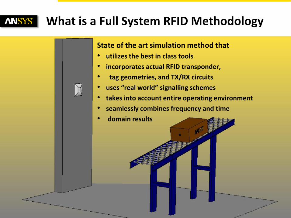
State of the art simulation method that
• utilizes the best in class tools
• incorporates actual RFID transponder,
• tag geometries, and TX/RX circuits
• uses “real world” signalling schemes
• takes into account entire operating environment
• seamlessly combines frequency and time
• domain results
What is a Full System RFID Methodology
3 © 2014 ANSYS, Inc. November 12, 2015 ANSYS Confidential
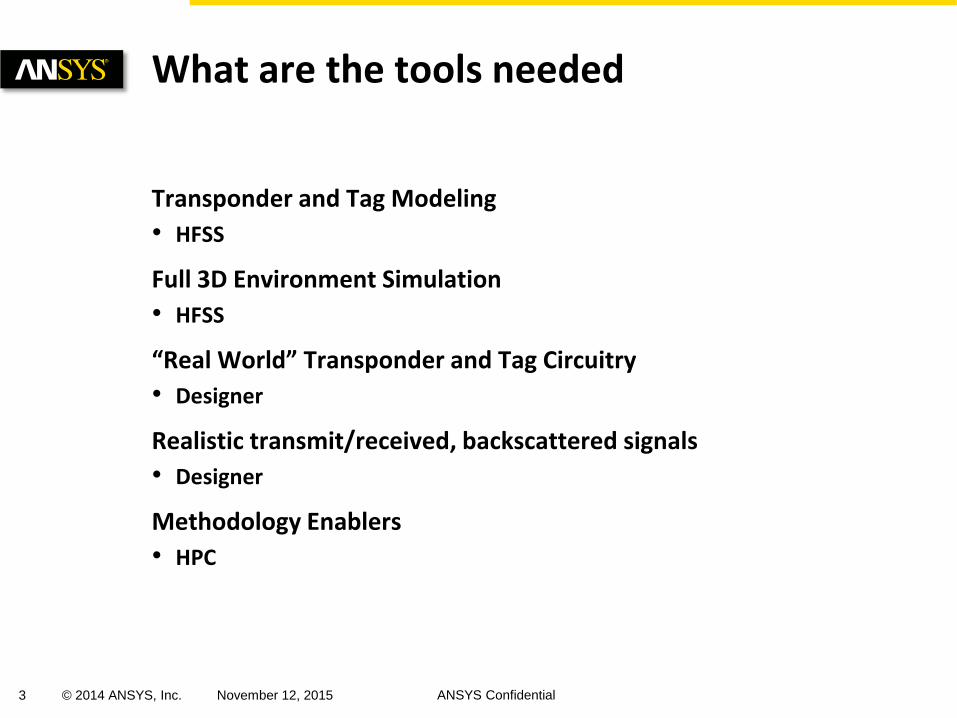
Transponder and Tag Modeling
• HFSS
Full 3D Environment Simulation
• HFSS
“Real World” Transponder and Tag Circuitry
• Designer
Realistic transmit/received, backscattered signals
• Designer
Methodology Enablers
• HPC
What are the tools needed
4 © 2014 ANSYS, Inc. November 12, 2015 ANSYS Confidential
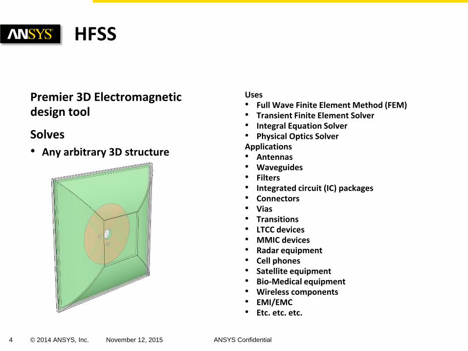
Premier 3D Electromagnetic design tool
Solves
• Any arbitrary 3D structure
Uses • Full Wave Finite Element Method (FEM) • Transient Finite Element Solver • Integral Equation Solver • Physical Optics Solver Applications • Antennas • Waveguides • Filters • Integrated circuit (IC) packages • Connectors • Vias • Transitions • LTCC devices • MMIC devices • Radar equipment • Cell phones • Satellite equipment • Bio-Medical equipment • Wireless components • EMI/EMC • Etc. etc. etc.
HFSS
5 © 2014 ANSYS, Inc. November 12, 2015 ANSYS Confidential
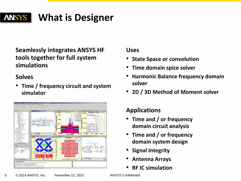
Seamlessly integrates ANSYS HF tools together for full system simulations
Solves
• Time / frequency circuit and system simulator
Uses
• State Space or convolution
• Time domain spice solver
• Harmonic Balance frequency domain solver
• 2D / 3D Method of Moment solver
Applications
• Time and / or frequency domain circuit analysis
• Time and / or frequency domain system design
• Signal Integrity
• Antenna Arrays
• RF IC simulation
What is Designer
6 © 2014 ANSYS, Inc. November 12, 2015 ANSYS Confidential
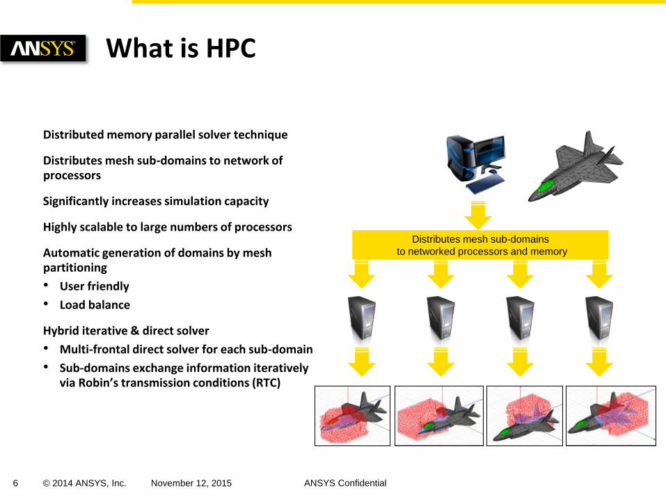
Distributed memory parallel solver technique
Distributes mesh sub-domains to network of processors
Significantly increases simulation capacity
Highly scalable to large numbers of processors
Automatic generation of domains by mesh partitioning
• User friendly
• Load balance
Hybrid iterative & direct solver
• Multi-frontal direct solver for each sub-domain
• Sub-domains exchange information iteratively via Robin’s transmission conditions (RTC)
What is HPC
Distributes mesh sub-domains
to networked processors and memory
7 © 2014 ANSYS, Inc. November 12, 2015 ANSYS Confidential
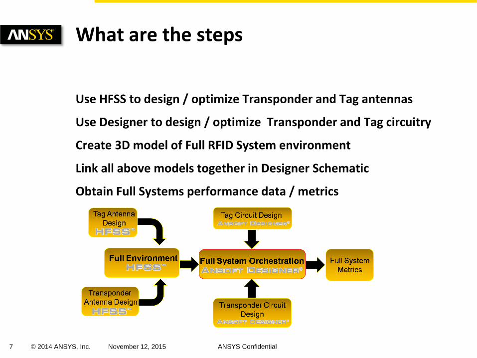
Use HFSS to design / optimize Transponder and Tag antennas
Use Designer to design / optimize Transponder and Tag circuitry
Create 3D model of Full RFID System environment
Link all above models together in Designer Schematic
Obtain Full Systems performance data / metrics
What are the steps
8 © 2014 ANSYS, Inc. November 12, 2015 ANSYS Confidential
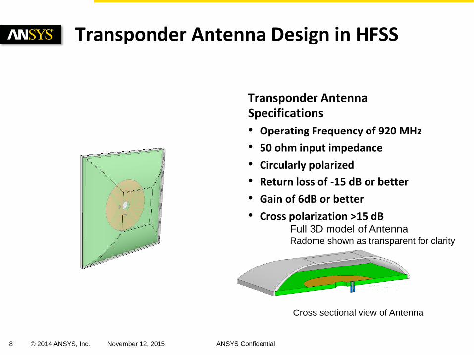
Transponder Antenna Specifications
• Operating Frequency of 920 MHz
• 50 ohm input impedance
• Circularly polarized
• Return loss of -15 dB or better
• Gain of 6dB or better
• Cross polarization >15 dB
Transponder Antenna Design in HFSS
Full 3D model of Antenna Radome shown as transparent for clarity
Cross sectional view of Antenna
9 © 2014 ANSYS, Inc. November 12, 2015 ANSYS Confidential
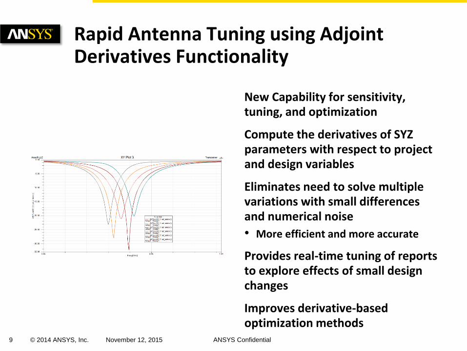
New Capability for sensitivity, tuning, and optimization
Compute the derivatives of SYZ parameters with respect to project and design variables
Eliminates need to solve multiple variations with small differences and numerical noise
• More efficient and more accurate
Provides real-time tuning of reports to explore effects of small design changes
Improves derivative-based optimization methods
Rapid Antenna Tuning using Adjoint Derivatives Functionality
10 © 2014 ANSYS, Inc. November 12, 2015 ANSYS Confidential
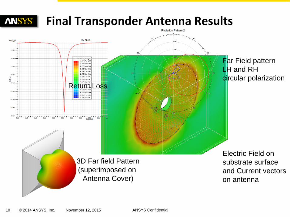
Final Transponder Antenna Results
Return Loss
3D Far field Pattern
(superimposed on
Antenna Cover)
Far Field pattern
LH and RH
circular polarization
Electric Field on
substrate surface
and Current vectors
on antenna
11 © 2014 ANSYS, Inc. November 12, 2015 ANSYS Confidential
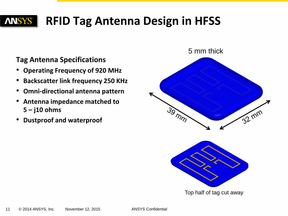
Tag Antenna Specifications
• Operating Frequency of 920 MHz
• Backscatter link frequency 250 KHz
• Omni-directional antenna pattern
• Antenna impedance matched to 5 – j10 ohms
• Dustproof and waterproof
RFID Tag Antenna Design in HFSS
5 mm thick
Top half of tag cut away
12 © 2014 ANSYS, Inc. November 12, 2015 ANSYS Confidential
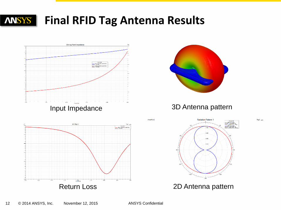
Final RFID Tag Antenna Results
Return Loss
Input Impedance 3D Antenna pattern
2D Antenna pattern
13 © 2014 ANSYS, Inc. November 12, 2015 ANSYS Confidential
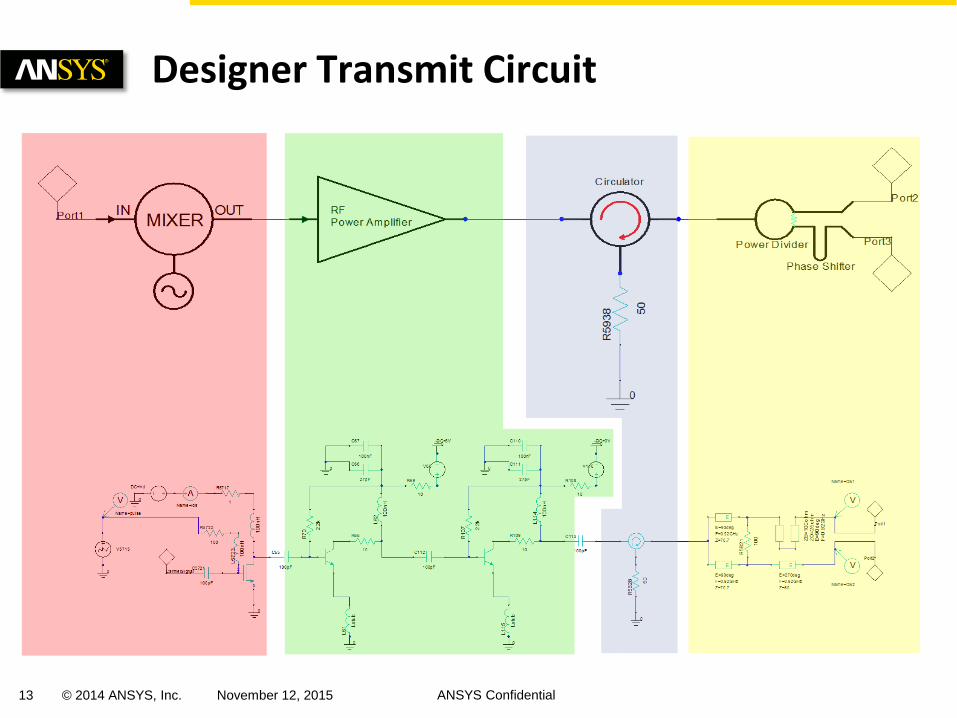
Designer Transmit Circuit
14 © 2014 ANSYS, Inc. November 12, 2015 ANSYS Confidential
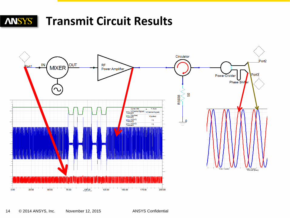
Transmit Circuit Results
15 © 2014 ANSYS, Inc. November 12, 2015 ANSYS Confidential
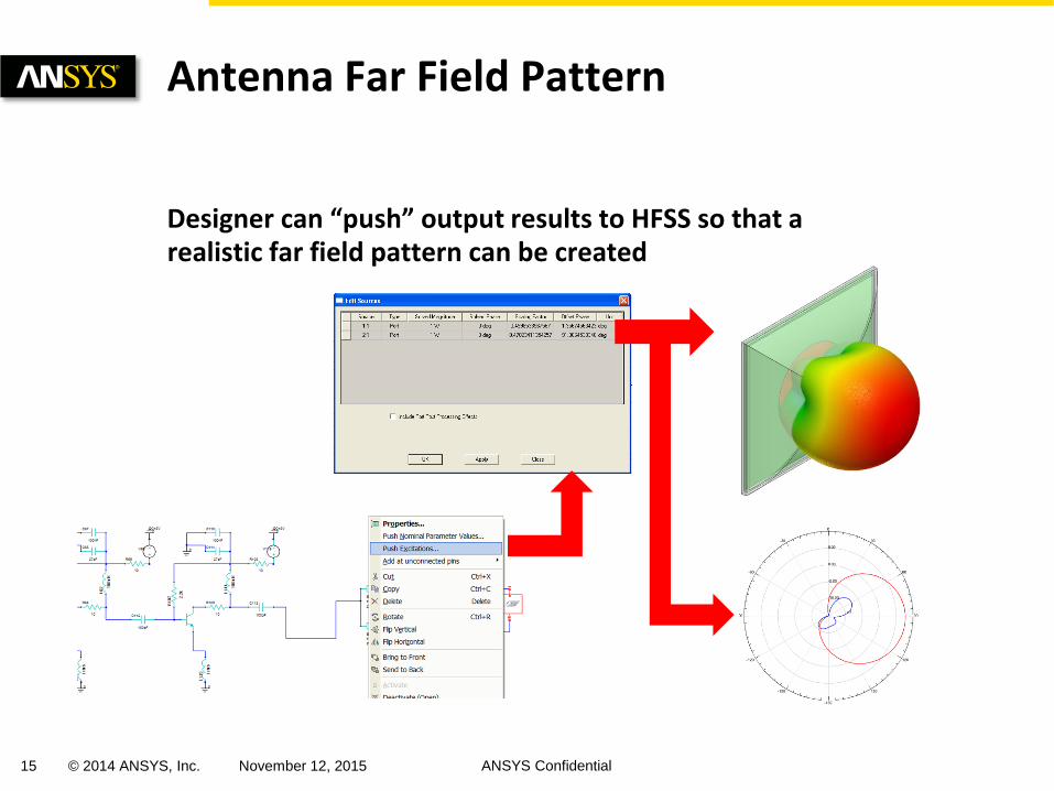
Designer can “push” output results to HFSS so that a realistic far field pattern can be created
Antenna Far Field Pattern
16 © 2014 ANSYS, Inc. November 12, 2015 ANSYS Confidential
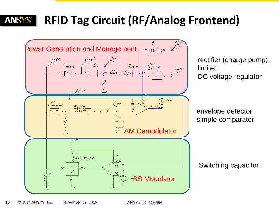
RFID Tag Circuit (RF/Analog Frontend)
Power Generation and Management
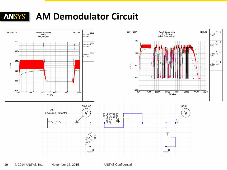
AM Demodulator
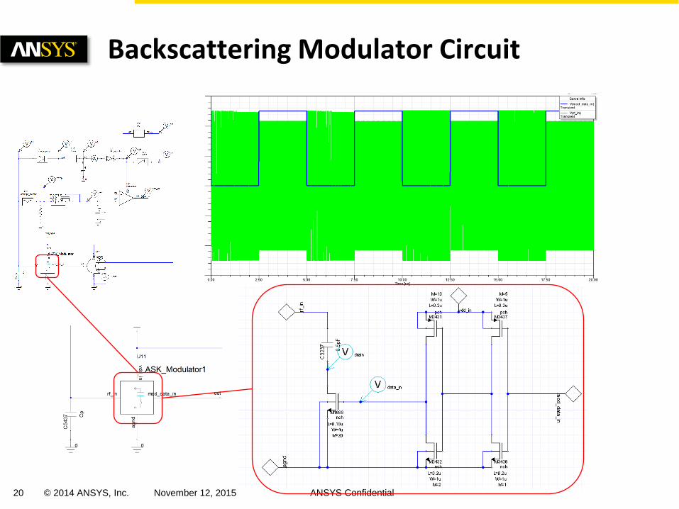
BS Modulator
rectifier (charge pump),
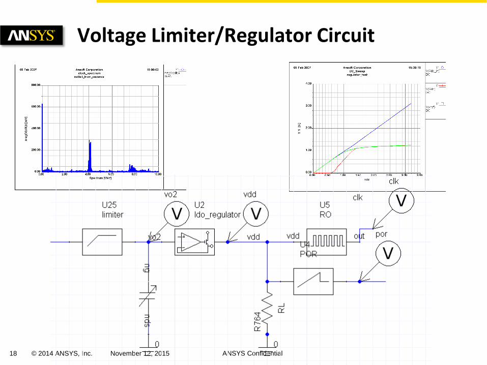
limiter,
DC voltage regulator
envelope detector
simple comparator
Switching capacitor
17 © 2014 ANSYS, Inc. November 12, 2015 ANSYS Confidential
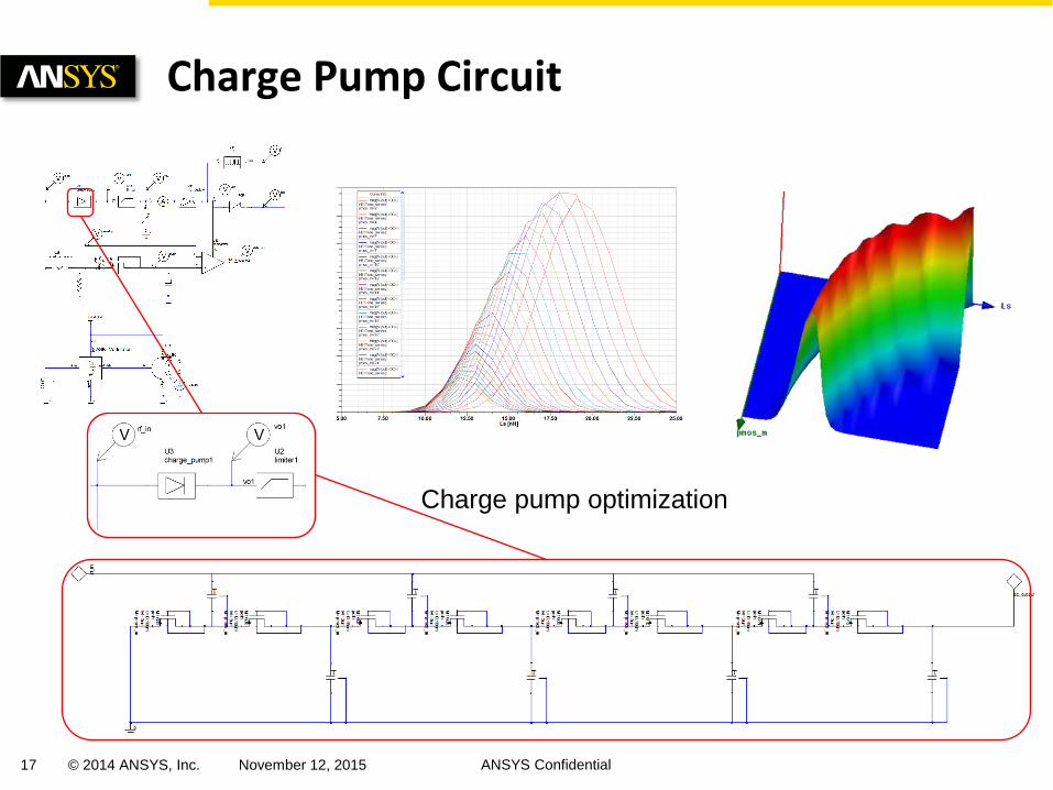
Charge Pump Circuit
Charge pump optimization
18 © 2014 ANSYS, Inc. November 12, 2015 ANSYS Confidential
Voltage Limiter/Regulator Circuit
19 © 2014 ANSYS, Inc. November 12, 2015 ANSYS Confidential
AM Demodulator Circuit
20 © 2014 ANSYS, Inc. November 12, 2015 ANSYS Confidential
Backscattering Modulator Circuit
21 © 2014 ANSYS, Inc. November 12, 2015 ANSYS Confidential
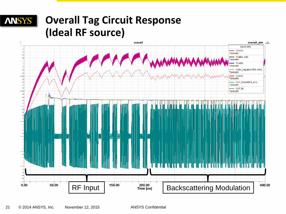
Overall Tag Circuit Response (Ideal RF source)
RF Input Backscattering Modulation
22 © 2014 ANSYS, Inc. November 12, 2015 ANSYS Confidential
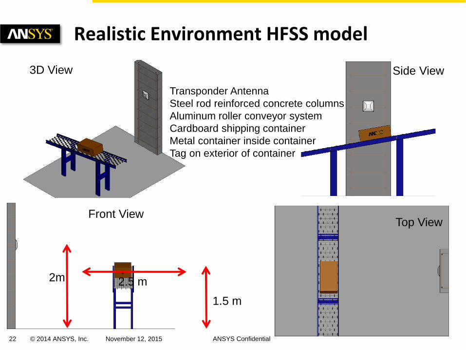
Realistic Environment HFSS model
2.5 m
Side View
Top View Front View
Transponder Antenna
Steel rod reinforced concrete columns
Aluminum roller conveyor system
Cardboard shipping container
Metal container inside container
Tag on exterior of container
3D View
1.5 m
2m
23 © 2014 ANSYS, Inc. November 12, 2015 ANSYS Confidential
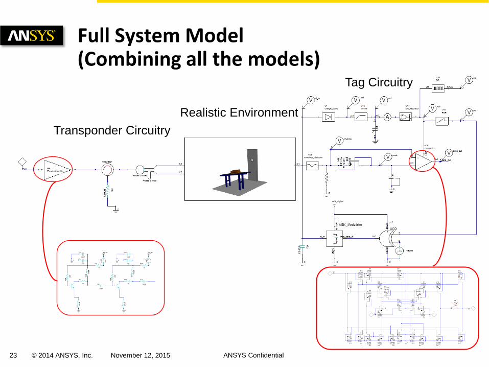
Full System Model (Combining all the models)
Transponder Circuitry
Realistic Environment
Tag Circuitry
24 © 2014 ANSYS, Inc. November 12, 2015 ANSYS Confidential
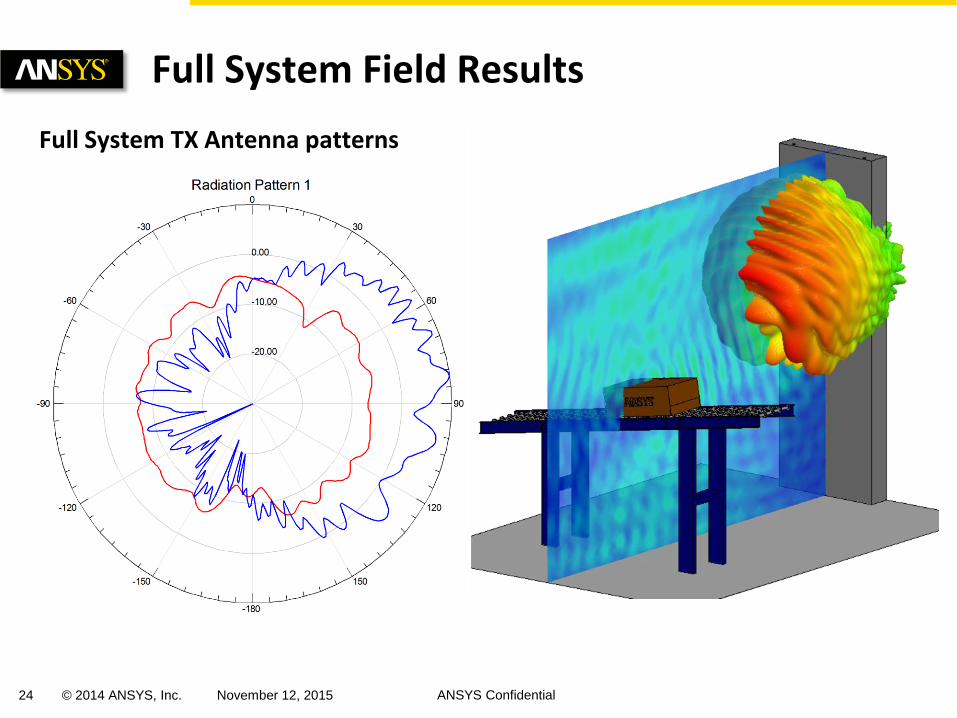
Full System Field Results
Full System TX Antenna patterns
25 © 2014 ANSYS, Inc. November 12, 2015 ANSYS Confidential
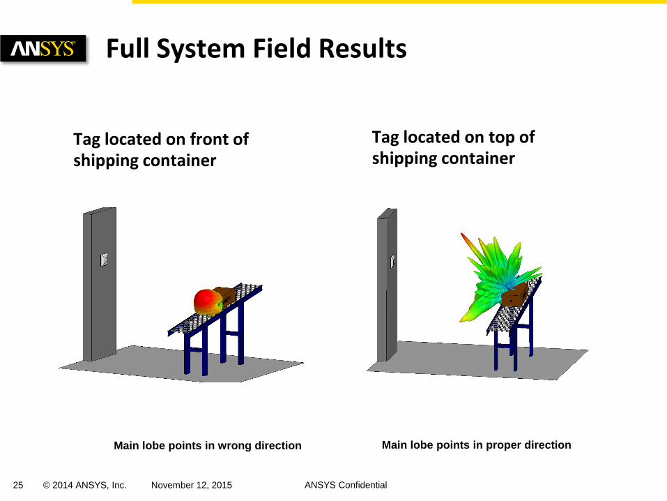
Full System Field Results
Tag located on front of shipping container
Tag located on top of shipping container
Main lobe points in wrong direction Main lobe points in proper direction
26 © 2014 ANSYS, Inc. November 12, 2015 ANSYS Confidential
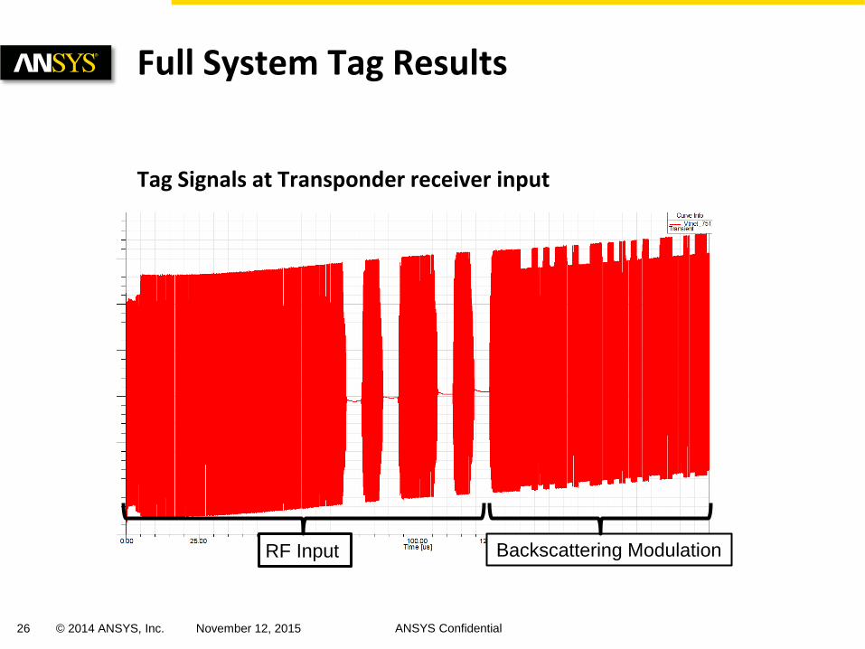
Tag Signals at Transponder receiver input
Full System Tag Results
RF Input Backscattering Modulation
27 © 2014 ANSYS, Inc. November 12, 2015 ANSYS Confidential
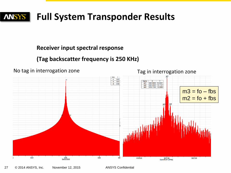
Receiver input spectral response
(Tag backscatter frequency is 250 KHz)
Full System Transponder Results
No tag in interrogation zone Tag in interrogation zone
m3 = fo – fbs
m2 = fo + fbs
28 © 2014 ANSYS, Inc. November 12, 2015 ANSYS Confidential
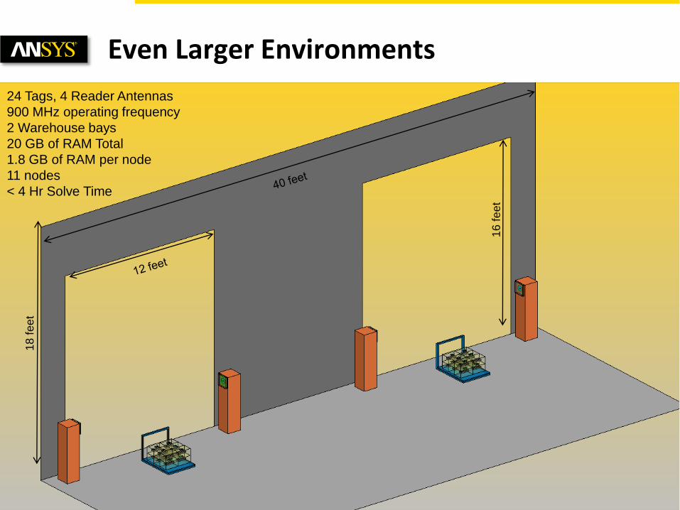
Even Larger Environments
24 Tags, 4 Reader Antennas
900 MHz operating frequency
2 Warehouse bays
20 GB of RAM Total
1.8 GB of RAM per node
11 nodes
< 4 Hr Solve Time
18
fe
et
16
fe
et
29 © 2014 ANSYS, Inc. November 12, 2015 ANSYS Confidential
Using the combination of HFSS and Designer it is easily possible to design, optimize, and predict the performance of an RFID system in its intended environment.
Additionally, multiple arbitrarily located and oriented tags can be included in the model as well.
Larger environments are possible.
Random noise sources can also be included in the full system model.
Final thoughts