the geoweb earth retention system technical overview
TRANSCRIPT

PRESTO
GEOWEB® EARTH RETENTION SYSTEMTECHNICAL OVERVIEW
PRESTO GEOSYSTEMS 670 N PERKINS STREET, APPLETON, WISCONSIN, USA 54914 Ph: 920-738-1707 or 800-548-3424 ■ Fax: 920-738-1222 e-mail: [email protected]
GEOWEB GRAVITY WALL
FOUNDATION SOIL
BACKFILLBACKFILLSOILSOIL
RETAINEDSOIL
GEOWEBLAYERS
GEOWEB ZONED GRAVITY WALL
FOUNDATION SOIL
BACKFILLBACKFILLSOILSOIL
RETAINEDSOIL
GEOWEBLAYERS
GEOCOMPOSITE GRAVITY WALL
FOUNDATION SOIL
BACKFILLBACKFILLSOILSOIL
RETAINEDSOIL
GEOWEBLAYERS
GEOSYNTHETICGEOSYNTHETIC
GEOWEB FACIA
FOUNDATION SOIL
STRUCTURALLYSTABLESOIL OR ROCKGEOWEB
LAYERS
BACKFILLSOIL
FOUNDATION SOIL
FREE-STANDINGGEOCOMPOSITE WALL
GEOWEBLAYERS
GEOSYNTHETIC
FREE-STANDINGGEOWEB WALL
GEOWEBLAYERS
FOUNDATION SOIL
WWW.PRESTOGEO.COM/ GWERTO 15 FEB-08
PRESTO
GEOWEB® EARTH RETENTION SYSTEMTECHNICAL OVERVIEW
GWERTO 15 FEB-08
Table of Contents Introduction ................................................................................................................................................... 1
Figure 1 Vegetated Wall ................................................................................................................... 1 Table 1 Geoweb Earth Retention Structure Selection Guidelines.................................................... 2
Geoweb® System Advantages..................................................................................................................... 2 Durability ................................................................................................................................................... 2 Performance.............................................................................................................................................. 3 Ease of Construction................................................................................................................................. 3 Infill Materials ............................................................................................................................................ 3
Figure 2 Installed Cost Comparison ................................................................................................. 3 Economics................................................................................................................................................. 4 Environment .............................................................................................................................................. 4
Engineering Concepts .................................................................................................................................. 4 Geoweb Wall Selection................................................................................................................................. 4 Global Stability .............................................................................................................................................. 5
Figure 3 Global Slope Stability.......................................................................................................... 5 Design Guidelines......................................................................................................................................... 5
Figure 4 Design Model, Gravity Geoweb Wall.................................................................................. 5 Figure 5 Design Model, Soil Reinforced Geoweb Wall..................................................................... 5
Step 1 Determine the earth pressure coefficient .................................................................................. 6 External Stability ........................................................................................................................................... 6
Figure 6 External Stability Modes of Failure ..................................................................................... 6 Step 2 Determine the earth forces ....................................................................................................... 6 Step 3 Determine the weight of the wall ............................................................................................... 7 Step 4 Determine the Factor of Safety against sliding ......................................................................... 7 Step 5 Determine the Factor of Safety against overturning ................................................................. 7 Step 6 Determine the Factor of Safety against bearing capacity failure .............................................. 8
Internal Stability ............................................................................................................................................ 8 Figure 7 Internal Stability Modes of Failure ...................................................................................... 8
Step 7 Determine the Factor of Safety against an internal sliding failure ............................................ 8 Step 8 Determine the Factor of Safety against internal overturning .................................................... 9 Step 9 Determine the design properties of the geosynthetic reinforcement ........................................ 9 Step 10 Determine the load applied to each geosynthetic reinforcement layer................................... 9

PRESTO
GEOWEB® EARTH RETENTION SYSTEMTECHNICAL OVERVIEW
GWERTO 15-FEB-08
Step 11 Determine the Factor of Safety against tensile overstress......................................................9 Step 12 Determine the Factor of Safety against pullout .....................................................................10
Local Stability ..............................................................................................................................................10 Figure 8 Local Stability Modes of Failure ........................................................................................10
Step 13 Determine the Factor of Safety against failure of the connection .........................................10 Step 14 Probability of bulging between layers....................................................................................11 Step 15 Maximum Unreinforced Height..............................................................................................11 Step 16 Properly designed drainage system......................................................................................11
Available Tools & Services..........................................................................................................................11 Disclaimer....................................................................................................................................................11 References ..................................................................................................................................................12

PRESTO
GEOWEB® EARTH RETENTION SYSTEMTECHNICAL OVERVIEW
GWERO 15-Feb-08 COPYRIGHT 2008 – PRESTO PRODUCTS CO. PAGE 1 OF 12
Introduction The use of earth retention structures has expanded in recent years as (1) transportation upgrades are increasingly constructed within existing rights-of-way and (2) development of prime industrial, residential, and commercial property has spilled on to sites requiring additional improvement. The Geoweb cellular confinement system has been specifically developed to meet the challenges that change-in-grade construction present, particularly when foundation conditions are predominately compressible soils. The versatility of the Geoweb cellular confinement system is shown on the front page, illustrating the basic earth retention structures that can be formed using the product. Presented here is an explanation of technical and design requirements for selecting the most appropriate Geoweb earth retention structure for your project.
INFILLRETAINEDSOIL
SUBDRAIN150 mmor 6.0 in
GEOWEBSECTION
TOPSOIL INFILLWITH VEGETATION
INFILLRETAINEDSOIL
SUBDRAIN150 mmor 6.0 in
GEOWEBSECTION
TOPSOIL INFILLWITH VEGETATION
Figure 1 Vegetated Wall
Earth retention structures are commonly incorporated into civil construction work to accommodate irregular topography and to facilitate grade separation. Their use, in place of simple earth slopes, is generally dictated by the severity of grade change and by availability or cost of land within a project site. Typical applications utilizing this technology are:
• Widening within existing rights-of-way • Adding a lane of traffic or parking • Grading development sites to boundary limits • Providing truck or emergency vehicle access • Expanding sports fields & storage yards • Reshaping & stabilizing storm water channels • Building storm water detention structures • Repair of failed slopes and retention structures • Safety barriers along transportation corridors • Energy absorbers • Noise attenuation walls
A typical Geoweb earth retention structure is illustrated in Figure 1.
The primary function of an earth structure is to provide a very steep, or in some cases vertical surface, which is erosion resistant and structurally stable under its self-weight and externally imposed loads. The near vertical change in grade requires that earth materials be stacked higher and steeper than their internal shear strength properties will permit. Consequently, the magnitude of lateral earth pressure, which these earth structures must resist, is directly related to:
• Height of the change in grade, • Internal shear strength of the earth materials, • Geometry of slope above the structure, and • Magnitude of any imposed surcharge loading.

PRESTO
GEOWEB® EARTH RETENTION SYSTEMTECHNICAL OVERVIEW
PAGE 2 OF 12 COPYRIGHT 2008 – PRESTO PRODUCTS CO. GWERO 15-Feb-08
Table 1 Geoweb Earth Retention Structure Selection Guidelines
GRAVITY SYSTEMS GEOCOMPOSITE SYSTEMS
Constraints Full Geoweb Zoned Geoweb Geosynthetic / Geoweb
Slope
Wall Heights < 6.1 m (20 ft) >3.5 m (12 ft) > 3 m (10 ft) >2 m (7 ft)
Limited Excavation Area Acceptable Acceptable Possible Unfeasible
Foundation Conditions Competent to Variable
Competent to Variable
Competent to Poor
Competent to Poor
Infill/Backfill Requirements Granular Only Granular Only Granular / Site Soils
Granular / Site Soils
Availability of Granular Fill Plentiful Plentiful Limited to Scarce
Limited to Scarce
The project sites soil conditions, availability of suitable backfill materials, economics and the completed aesthetics govern which Geoweb retention structure would be most appropriate. Table 1 provides a brief summary of the key criteria that favor certain types of Geoweb earth retention structures.
The basic Geoweb system can be readily adapted to a wide range of design requirements and site conditions. The extreme versatility of Geoweb results from its inherent flexibility, unique load-deformation behavior, and suitability with a wide range of infill materials and foundation soils. This permits Geoweb earth retention structures to cost-effectively replace conventional earth retention structures such as:
• Concrete cantilever • Mechanically Stabilized Earth (MSE) or Earth-anchored systems • Soldier pile & lagging with or without tiebacks • Concrete gravity • Concrete crib • Timber crib • Sheet pile
Geoweb® System Advantages
Durability Retention structures using the Geoweb cellular confinement system provide superior resistance to attack from chemicals, water and freeze-thaw that beset many earth retention systems. Polyethylene plastic used to make Geoweb products is resistant to penetration by water, eliminating any potential for cracking, spalling, splintering, or corrosion that initiates deterioration of concrete, steel, and timber-based earth retention systems. Consequently, the system is well suited to structures that are exposed to seawater, extreme pH soils, or road de-icing salts and chemicals.
Components used in Geoweb earth retention structures are durable. The longevity of naturally occurring aggregate and other soils utilized in Geoweb earth retention structures has been well documented in the engineering literature. Geosynthetic reinforcement used to stabilize backfill soils is manufactured from specially formulated polymers engineered to resist creep and environmental degradation throughout the design life of the structure. By implementing geosynthetic industry standard Task Force 27 design guidelines, a safe working strength, LTDS, for geosynthetic reinforcement can be determined for any design life ranging from 5 to 120 years.

PRESTO
GEOWEB® EARTH RETENTION SYSTEMTECHNICAL OVERVIEW
GWERTO 15-Feb-08 COPYRIGHT 2008 – PRESTO PRODUCTS CO. PAGE 3 OF 12
Performance Geoweb confinement systems provide the most flexible retention structure available today. This flexibility permits Geoweb walls to be constructed over more variable and compressible foundation soils than allowed with conventional earth retention structures having rigid structural facing systems. This flexibility provides the designer and owner of earth retention structures a confined mass that can tolerate large deformation without loss of structural integrity or adversely affecting the aesthetics, especially with vegetated facing treatment. Since the Geoweb facia and soil reinforced system are constructed using similar soils, differential movement is minimized, allowing construction on foundation soils that would require a deep foundation for more conventional retaining walls.
Ease of Construction Individual Geoweb sections are compact and lightweight. A single forty-foot container can hold the required number of sections to construct 1,240 m² (13,300 ft²) of Geoweb wall face, making shipping costs, even to remote locations, very reasonable. Installers can easily handle the Geoweb sections in all temperatures, making it one of the fastest manually constructed facing systems available. Sections are quickly expanded, positioned, infilled, and compacted by typical construction crews. By extending soil reinforcement, such as geotextiles and geogrids, between Geoweb layers at predetermined elevations, the system becomes an MSE structure.
Infill Materials Multi-layer Geoweb sections in earth retention structures are generally infilled with select, free-draining granular materials, such as sand, gravel or graded stone. To enhance the erosion resistance, the outer Geoweb cells may be filled with concrete. To enhance appearance, the outer Geoweb cells may be filled with vegetated topsoil (see Figure 1).
The polymer nature of both the Geoweb wall sections and the geosynthetic soil reinforcement also permits the use of some fine grained cohesive soil backfill (i.e., CL, ML, SC with PI<20). Since corrosion of the Geoweb facing or geosynthetic soil-reinforcement-elements is typically not possible, utilization of available cohesive soils is an important factor in the selection and use of soil reinforced Geoweb retaining walls. Use of available site soils generally translates into significant cost savings over other types of soil retention structures. However, site soils must be verified by site-specific engineering for a given project.
CO
ST ($
/m²)
CO
ST ($
/ft²)
3 6 9 12 15
RETENTION SYSTEMS
WALLS
SLOPES
$10
$20
$30
$40$400
$300
$200
$100
MSE CONCRETE BLOCKS /CONCRETE PANELS /
REINFORCED CONCRETE
GABION
STEEL BIN
WALL HEIGHT (m)
WALL HEIGHT (ft)10 20 30 40 50
GEOSYNTHETICSTEEL REINF.
GEOWEB EARTH
Figure 2 Installed Cost Comparison

PRESTO
GEOWEB® EARTH RETENTION SYSTEMTECHNICAL OVERVIEW
PAGE 4 OF 12 COPYRIGHT 2008 – PRESTO PRODUCTS CO. GWERO 15-Feb-08
Economics Geoweb retention structures are cost competitive with other conventional earth retention systems (see Figure 2). This graph illustrates that, depending upon wall height, Geoweb retention structures offer a 25 to 50 % cost savings over conventional cast-in-place concrete retaining walls. Although the installed cost for all earth retention systems will vary with site specific conditions such as; accessibility, soil conditions, cost of infill and compaction of infill, labor rates, surcharge loading, length of wall, etc.. This installed cost graph (Figure 2), indicates relative cost competitiveness by comparing Geoweb structures built in 1988 with the cost of more conventional earth retention construction methods as compiled by the California DOT in 1986.
Environment Geoweb retention walls represent an advanced system in protecting the environment. The polymer based products utilized with naturally occurring soils/aggregates comprise a system which is extremely resistant to deterioration. Furthermore, if deterioration begins, the process is slow, and harmful toxin or contaminant by-products are not generated.
The environmental impact of a retaining wall on an area can be visual or even physical, as an obstacle to wildlife. The Geoweb retention wall system minimizes both impacts by blending into the natural environment with vegetated facings and different colored (black, tan, green and white) products. The vegetated face treatment also provides a surface which has noise absorbing tendencies.
Engineering Concepts The Geoweb system is a flexible, three-dimensional cellular confinement system, formed with surface-textured strips of polyethylene. The individual strips are inter-connected by a series of offset, full-depth, ultrasonically welded seams. When expanded, the strips form the walls of an integrated cellular (honeycomb) structure into which selected fill materials are placed and compacted. The engineering properties of the confined mass reflect the inherent strength of the compacted infill material and the high lateral restraint provided by the Geoweb cell. The load deformation performance of infilled Geoweb is significantly different from that of an equivalent mass of unconfined infill material. The confining cell structure imparts an effective cohesion to the infill material, thereby increasing its shear strength and stiffness. This improvement results from the hoop strength of the cell walls, the passive resistance of the adjacent cells and the high frictional interaction between the infill and the cell walls (Bathurst & Karpurapu). Consequently, a very efficient soil matrix is created by using the Geoweb cellular confinement system and granular soil infills.
The large frictional resistance between infilled layers permits stacking subsequent layers of Geoweb sections to create a composite structure that behaves as a monolithic gravity mass, which is flexible enough to conform to variable foundation conditions. This frictional resistance allows Geoweb sections to be used either as a self-contained gravity retaining wall or as a narrow, uniform facia system for soil-reinforced retaining walls.
Geoweb Wall Selection Selection of the appropriate Geoweb earth retention system will be governed by the project constraints shown in Table 1. The first step in systematically evaluating those criteria is to define the wall geometry, surcharge loading, excavation limits, and soil/groundwater conditions at the specific wall location. This is facilitated by generating a plan and profile drawing of the wall to understand its relationship to existing and proposed finish grades. The drawing should contain the location of any proposed or existing structures including underground utilities and property boundaries that may affect wall construction.
PRESTO
GEOWEB® EARTH RETENTION SYSTEMTECHNICAL OVERVIEW
GWERTO 15-Feb-08 COPYRIGHT 2008 – PRESTO PRODUCTS CO. PAGE 5 OF 12
Based upon wall location (cut or fill), foundation conditions, and the availability/cost of suitable granular infill soils, select the general type of Geoweb retention structure to design; gravity or soil-reinforced. Many combinations can result using these two basic configurations, with economics and site constraints being the determining factors.
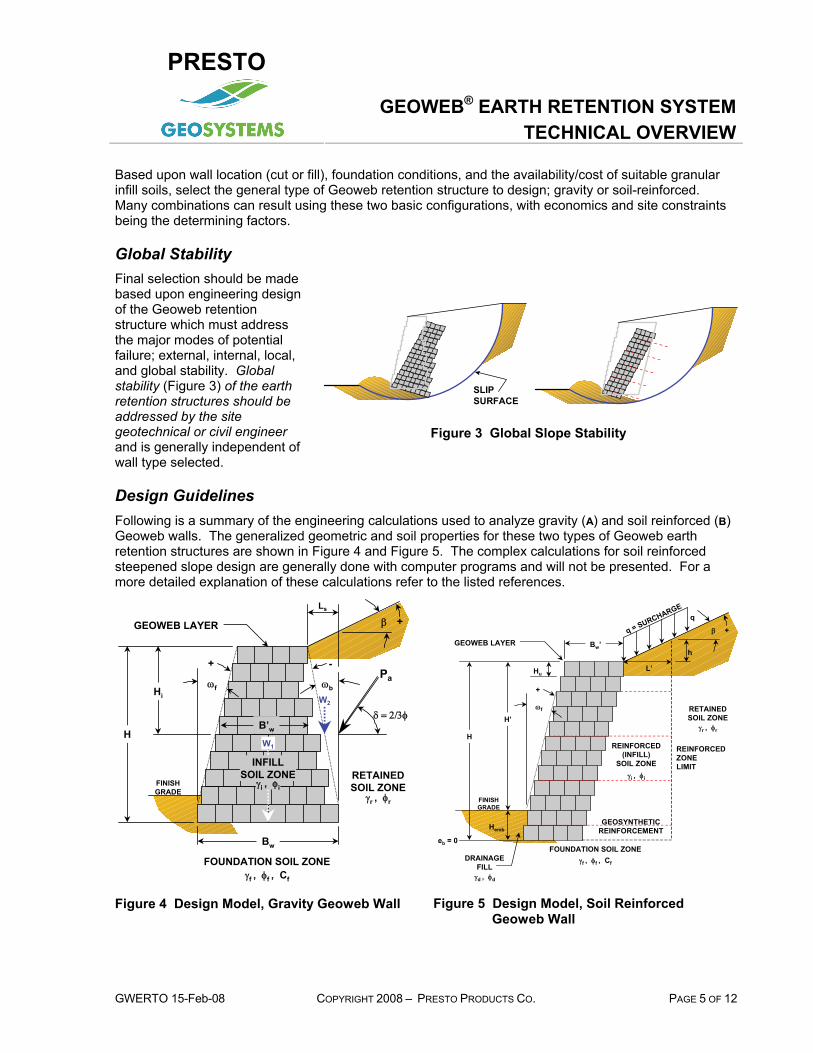
Global Stability Final selection should be made based upon engineering design of the Geoweb retention structure which must address the major modes of potential failure; external, internal, local, and global stability. Global stability (Figure 3) of the earth retention structures should be addressed by the site geotechnical or civil engineer and is generally independent of wall type selected.
SLIPSURFACE
Figure 3 Global Slope Stability
Design Guidelines Following is a summary of the engineering calculations used to analyze gravity (A) and soil reinforced (B) Geoweb walls. The generalized geometric and soil properties for these two types of Geoweb earth retention structures are shown in Figure 4 and Figure 5. The complex calculations for soil reinforced steepened slope design are generally done with computer programs and will not be presented. For a more detailed explanation of these calculations refer to the listed references.
FINISHGRADE
FOUNDATION SOIL ZONEγf , φf , Cf
RETAINEDSOIL ZONE
γr , φr
β +
Hi
H
Pa
δ = 2/3φ B’w
Bw
ωf ωb
+ -
GEOWEB LAYER
Ls
W1
W2
γi , φi
INFILLSOIL ZONE
Figure 4 Design Model, Gravity Geoweb Wall
q = SURCHARGE
FINISHGRADE
FOUNDATION SOIL ZONEγf , φf , Cf
RETAINEDSOIL ZONE
γr , φr
REINFORCED(INFILL)
SOIL ZONEγi , φi
DRAINAGEFILL
γd , φd
GEOWEB LAYER
ωf
+
β +
GEOSYNTHETICREINFORCEMENT
q
L’
h
Hu
Hemb
H
H’
Bw’
REINFORCEDZONELIMIT
eb = 0
Figure 5 Design Model, Soil Reinforced Geoweb Wall

PRESTO
GEOWEB® EARTH RETENTION SYSTEMTECHNICAL OVERVIEW
PAGE 6 OF 12 COPYRIGHT 2008 – PRESTO PRODUCTS CO. GWERO 15-Feb-08
Step 1 Determine the earth pressure coefficient
Determine the earth pressure coefficient, Ka:
A. For Gravity walls (Full & Zoned) utilize Coulomb earth pressure theory Ka (after Jumikis):
NOTE: Assume ωb = 0 for individual analysis of Geoweb wall sections.
2
2
2
)cos()cos()sin()sin(1)cos(cos
)(cos
⎥⎥⎦
⎤
⎢⎢⎣
⎡
+−−+
+−
+=
βωδωβφδφδωω
ωφ
bbbb
baK
B. For Soil Reinforced walls utilize Rankine earth pressure theory, Ka’ (after AASHTO, FHWA, & Task Force 27):
Ka' =− −
+ −cos
cos cos cos
cos cos cosβ
β β
β β
2 2
2 2
φ
φ
External Stability The general failure modes for external stability are shown in Figure 6.
HORIZONTAL MOVEMENT
BASE SLIDING OVERTURNING
ROTATION
MOMENT
ROTATION
BEARING CAPACITY
TILT
SETTLEMENT
HORIZONTAL MOVEMENT
BASE SLIDING OVERTURNING
ROTATION
MOMENT
ROTATION
BEARING CAPACITY
TILT
SETTLEMENT
Figure 6 External Stability Modes of Failure
Step 2 Determine the earth forces
Determine the earth forces acting for external stability: δγ cos5.0 2HK ra=shP A. For gravity walls use total height of stacked
Geoweb sections, H: δγ sin5.0 2HK ra=svP
δcosHqKa=qhP
δsinHqKa=qvP
B. For soil reinforced walls use height (H+h) at the back of the reinforced soil mass and Ka' based upon φr:
( )Ps = +0 5 2. cK H ha rγ βos
( )Pq = +K q H ha cos β

PRESTO
GEOWEB® EARTH RETENTION SYSTEMTECHNICAL OVERVIEW
GWERTO 15-Feb-08 COPYRIGHT 2008 – PRESTO PRODUCTS CO. PAGE 7 OF 12
Step 3 Determine the weight of the wall
( ) ( )[ ] ifw HBH γωtan5.0 2−=W' Determine the weight of the wall for sliding resistance:
A. For gravity walls use total weight of stacked Geoweb sections, plus weight of retained soil in front of heel of base layer, plus dead load surcharge in front of heel of base layer.
rS21 LWW γ++=W'
for ωb W W≤ =0, '
for ( )ω ωb bW W H⟩ = +0 0 5 2, ' . tan γ i
B. For soil reinforced walls use entire width of the reinforced zone, L, to resist sliding: ( ) ( ) ( )Wr = − +⎡
⎣⎢⎤⎦⎥
H L H h L'f i0 5 0 52. tan .ω γ
Step 4 Determine the Factor of Safety against sliding
Determine the Factor of Safety against sliding, FSsl. Conceptually this is the sliding resistance generated at the base of the structure due to self-weight, divided by the lateral forces trying to move the structure outward, as shown in Figure 6. Generally, a FSsl greater than 1.5 is acceptable for design.
A. For gravity walls determine sliding resistance along base width, Bw, using lowest value of φi or φf: [φf used for illustrative purposes]
( )( ) wf
qhsh
fqvsv BcPP
tanPP'W+
+
++=
φslFS or
( )( )qhsl
iqvsv
PPtanPP'W
+
+=
φslFS
B. For soil reinforced walls determine sliding along base length of reinforcement, i.e. the width of the reinforced zone, L, using lowest value of φi , φd or φf: [φf used for illustrative purposes ]
( )qs
fr
PPtanW+
=φ
slFS
Note: The complexity of the remaining analyses dictates that the calculations be presented on a conceptual basis only. The exact equations will not be presented, but the reader is encouraged to obtain the appropriate reference to review the entire set of calculations for each analysis.
Step 5 Determine the Factor of Safety against overturning
Determine the Factor of Safety against overturning, FSot. The tendency for the structure to rotate is evaluated by comparing the moments resisting rotation, generated by the self weight of the structure, to the driving moments initiated by the imposed lateral loads. Overturning about the toe of the structure is analyzed to protect against excessive outward tilting and distortion. A FSot greater than 2.0 indicates suitable performance.
FSot =MomentsMoments
resisting
driving
A. For gravity walls determine the moments resisting overturning about the toe of base width, Bw as shown in Figure 4.
B. For soil reinforced walls sum moments about the toe of the structure, along the base length of geosynthetic reinforcement, L, as shown in Figure 5.

PRESTO
GEOWEB® EARTH RETENTION SYSTEMTECHNICAL OVERVIEW
PAGE 8 OF 12 COPYRIGHT 2008 – PRESTO PRODUCTS CO. GWERO 15-Feb-08
Step 6 Determine the Factor of Safety against bearing capacity failure
Determine the Factor of Safety against bearing capacity failure, FSbc. A conventional bearing capacity analysis is performed by comparing the calculated ultimate and allowable bearing pressure determined from soils testing and analysis by a geotechnical engineer to the calculated applied bearing stress using a conservative Meyerhof stress distribution. Generally, a FSbc greater than 2.0 for gravity walls and 2.5 for soil reinforced walls is acceptable.
FSbc =Bearing essure
Bearing Stressultimate
applied
Pr
A. For gravity walls, determine the applied bearing pressure for the effective base width, BW after taking eccentricity into account.
B. For soil reinforced walls, determine the applied bearing pressure along the base length of geosynthetic reinforcement, L, as shown in Figure 5.
Internal Stability The general modes of failure for internal stability are shown in Figure 7.
OVERTURNING
ROTATION
MOMENT
HORIZONTAL MOVEMENT
PULLOUT
HORIZONTAL MOVEMENT
TENSILE OVERSTRESS
HORIZONTAL MOVEMENT
INTERNAL SLIDING
MOVEMENTBETWEENLAYERS
HORIZONTAL MOVEMENT
INTERNAL SLIDING
MOVEMENTBETWEENLAYERS
Figure 7 Internal Stability Modes of Failure
Step 7 Determine the Factor of Safety against an internal sliding failure
Determine the Factor of Safety against an internal sliding failure, FSsl. This analysis is very similar to the earlier external sliding analysis, except the sliding surface exits through the Geoweb facia at some point less than the full wall height, H. It ensures that the reduction of Geoweb base width with increasing wall height for gravity walls, and increase in vertical spacing of geosynthetic reinforcement with height for soil-reinforced walls, does not create a more critical sliding surface than the full height of the structure (See External Stability, Step 4 Determine the Factor of Safety against sliding
FSsl =Sliding sis ce
Lateral Forcesapplied
Re tan

PRESTO
GEOWEB® EARTH RETENTION SYSTEMTECHNICAL OVERVIEW
GWERTO 15-Feb-08 COPYRIGHT 2008 – PRESTO PRODUCTS CO. PAGE 9 OF 12
). Generally, a FSsl greater than 1.5 is acceptable for design.
A. For gravity walls, determine the external applied lateral forces for each incremental height of wall, Hi, as measured from the top of wall to the bottom of each Geoweb layer. Compare that to the sliding resistance of the Geoweb base width, B'w for that layer, as shown in Figure 4.
B. For soil reinforced walls, determine the external applied lateral forces for each incremental height of wall, i.e. the bottom of each Geoweb layer. Compare the external applied lateral forces to the sliding resistance on the geosynthetic reinforcement, plus the sliding resistance at the layer width, Bw' where the potential failure surface may exit, as shown in Figure 5.
Step 8 Determine the Factor of Safety against internal overturning
Determine the Factor of Safety against internal overturning, Fsot, for each incremental height Hi, using the base width B'w at each layer level, see Figure 4. A FSot greater than 2.0 indicates suitable performance.
FSot =MomentsMoments
resisting
driving
A. For gravity walls determine the moments resisting overturning about the toe of each base width, B'w for each incremental height, Hi, see Figure 7.
This concludes the engineering analysis required for the design of gravity Geoweb walls, except for Step 16. The following analytical steps refer to soil reinforced walls only.
Step 9 Determine the design properties of the geosynthetic reinforcement
Determine the design properties of the geosynthetic reinforcement, consisting of a Long Term Design Strength LTDS and a coefficient of interaction Ci. Guidelines for interpreting manufacturer supplied test data on geosynthetic reinforcement and determining design properties are provided in industry standards for geosynthetic reinforcement (Task Force 27, Christopher et. al., & Simac et. al.). The procedures for determining LTDS include the partial safety factors for effects of; (1) creep performance, (2) construction induced site damage, (3) chemical durability, (4) biological durability, and (5) other uncertainty factors.
Step 10 Determine the load applied to each geosynthetic reinforcement layer
Determine the load applied to each geosynthetic reinforcement layer resisting the applied lateral stress to maintain internal stability. For internal stability Ka' is based upon φi:
B. For any selected vertical spacing of geosynthetic reinforcement, calculate the contributory area, Ac of each layer from the midpoints between layers above and below it. The applied force to each geosynthetic layer, Fg, will be equal to the average lateral stress at depth D (midpoint) of contributory area, as shown in this equation:
( )Fg = +γ βi a cD q K A' cos
Step 11 Determine the Factor of Safety against tensile overstress
Determine the Factor of Safety against tensile overstress, FStos. This factor of safety ensures there is sufficient allowable tensile capacity in the geosynthetic reinforcement to resist the applied force. For routine structures the FStos is generally considered sufficient when greater than 1.0. However, for more important structures, the FStos is usually increased to a minimum of 1.2. The FStos is calculated as:
FStos =LTDS
Fg

PRESTO
GEOWEB® EARTH RETENTION SYSTEMTECHNICAL OVERVIEW
PAGE 10 OF 12 COPYRIGHT 2008 – PRESTO PRODUCTS CO. GWERO 15-Feb-08
B. The FStos should be calculated for each geosynthetic layer in the proposed reinforcement layout (vertical spacing) for soil reinforced walls.
Step 12 Determine the Factor of Safety against pullout
Determine the Factor of Safety against pullout of the geosynthetic reinforcement FSpo for each reinforcement layer. This factor of safety ensures that the load applied to the geosynthetic reinforcement is transferred to the soil in the anchorage zone, i.e., beyond the internal failure plane. The minimum FSpo generally used in design is 1.5. The FSpo is calculated as follows:
FSpo =ACFg
B. The anchorage capacity, AC for any geosynthetic reinforcement, may be calculated using its pullout properties, Ci, available anchorage length, La and depth to the midpoint, d, of the anchorage length as shown in the following equation.
iiia tandCL2 φγ=AC
Local Stability Local stability analyses for the specific modes of failure shown in Figure 8, ensure that the Geoweb facia and soil reinforcement function together as one composite structure.
BULGINGFACING CONNECTION
Figure 8 Local Stability Modes of Failure
Step 13 Determine the Factor of Safety against failure of the connection
Determine the Factor of Safety against failure of the connection between the geosynthetic reinforcement and the Geoweb facing, FScs. Connection strength, Cs, of MSE wall systems are typically determined through full-scale laboratory testing of the specific geosynthetic reinforcement with the MSE facing system (Bathurst & Simac). Based on the granular fills normally used with Geoweb systems, the connection will have a predominantly frictional component and thus can be calculated with a reasonable degree of accuracy. For both critical and non-critical structures a minimum FScs of 1.5 is considered acceptable.
B. Calculate the factor of safety for connection strength FScs of each layer as: FScs =
CF
sg

PRESTO
GEOWEB® EARTH RETENTION SYSTEMTECHNICAL OVERVIEW
GWERTO 15-Feb-08 COPYRIGHT 2008 – PRESTO PRODUCTS CO. PAGE 11 OF 12
Step 14 Probability of bulging between layers
The probability of bulging between layers of geosynthetic reinforcement is determined by analyzing the shear capacity between Geoweb layers relative to the applied shear force. The applied shear force at the bottom of any layer is determined as the ‘total lateral earth force’, less the calculated applied force in the geosynthetic layers above that layer. The shear capacity Sc between Geoweb layers was determined using full scale testing (Bathurst 1987) and is available upon request.
B. The shear capacity SC should be calculated at the bottom of each Geoweb layer. The factor of safety for shear capacity FSsc is calculated as shown:
( )FSsc =
− ∑S
Lateral Force Fc
applied g layers above( )
Step 15 Maximum Unreinforced Height
B. The height of Geoweb wall above the uppermost geosynthetic reinforcement layer should be analyzed as a gravity structure to ensure adequate stability against sliding and overturning as described in calculation Step 7A and Step 8A.
Step 16 Properly designed drainage system
A properly designed drainage system is essential to good performance of Geoweb retaining walls. Generally, the granular infill used with Geoweb walls provides a good drainage media for relief of hydrostatic pressure and should be extended 300 to 600mm (12 to 24 in) behind the Geoweb sections as shown in Figure 1. If the retained soil has a finer gradation than the infill soil, it should be protected by a geotextile filter. For submerged walls, coastal structures, or sites with significant groundwater flow, a more comprehensive drainage design may be required.
Available Tools & Services Presto and Presto’s authorized distributors and representatives offer assistance to anyone interested in evaluating, designing, building or purchasing a Geoweb Earth Retention System. You may access these services by calling 800-548-3424 or 920-738-1707. In addition to working directly with you, the following design and construction resources are available for your use with the Geoweb Earth Retention System.
Material and CSI-format Specifications, System Components Guideline, Request for Project Evaluation, AutoCAD® Drawings, SPECMaker® Specification Development Tool, Technical Resources Library CD, videos
Design
Installation Guidelines, SPECMaker® Specification Development Tool, Technical Resources Library CD, videos
Construction
Disclaimer This document has been prepared for the benefit of customers interested in the Geoweb® Earth Retention System. It was reviewed carefully prior to publication. Presto assumes no liability and makes no guarantee or warranty as to its accuracy or completeness. Final determination of the suitability of any information or material for the use contemplated, or for its manner of use, is the sole responsibility of the user. Geosystems®, Geoweb®, ATRA®, and SPECMaker® are registered trademarks of Presto Products Company. AutoCAD® is a registered trademark of AutoDesk. © 2007

PRESTO
GEOWEB® EARTH RETENTION SYSTEMTECHNICAL OVERVIEW
PAGE 12 OF 12 COPYRIGHT 2008 – PRESTO PRODUCTS CO. GWERO 15-Feb-08
References 1. AASHTO, Standard Specifications for Highway Bridges, AASHTO, Washington, DC, 15 ed., (1992)
2. Bathurst, R.J., and Karpurapu, R., Large Scale Triaxial Compression Testing of Geocell Reinforced Granular Soils, Geotechnical Testing Journal, Vol. 16, pp. 296-303, Sept. (1993).
3. Bathurst, R.J., and Crowe, R.E., Recent Case Histories of Flexible Geocell Retaining Walls in North America, Recent Case Histories of Permanent Geosynthetic Reinforced Soil Retaining Walls, Tokyo, Japan (1992).
4. Bathurst, R.J. & Simac, M.R., Laboratory Testing of Modular Masonry Concrete Block-Geogrid Facing Connections, ASTM Symposium on Geosynthetic Soil Reinforcement Testing, STP 1190, Jan (1993).
5. Berg, R.R., Guidelines for Design, Specification, & Contracting of Geosynthetic Mechanically Stabilized Earth Slopes on Firm Foundations, publication of the US Department of Transportation - FHWA, Washington, DC (1993).
6. Caltrans, Alternative Earth Retaining Systems in California Highway Practice, (June 1986).
7. Christopher, B.R., et.al., Reinforced Soil Structures: Volume 1, Design and Construction Guidelines, Report No. FHWA-RD-89-043, FHWA, Washington, DC, (Nov. 1989).
8. Crowe, R.E., Steepened Slopes, presented at The Technical University of Nova Scotia lecture series on Applications of Geosynthetics to Civil Engineering, (1988).
9. Crowe, R.E., Bathurst, R.J. and Alston, C. Design and Construction of a Road Embankment Using Geosynthetics, 42'nd Canadian Geotechnical Conference, Winnipeg Manitoba, pp. 266-271, October 1989.
10. Jumikis, A.R., Soil Mechanics, D. Van Nostrand Company Inc., New York, NY (1962).
11. Simac, M.R., Bathurst, R.J., Berg, R.R., Lothspeich, S.E., Design Manual for Segmental Retaining Walls, National Concrete Masonry Association, Herndon, VA (1993).
12. Task Force 27, AASHTO-AGC-ARTBA Joint Committee on In Situ Soil Improvement Techniques: Guidelines for the Design of Mechanically Stabilized Earth Walls, AASHTO, Washington, DC, August (1990).
13. Task Force 27, AASHTO-AGC-ARTBA Joint Committee on In Situ Soil Improvement Techniques: "Design Guidelines for Use of Extensible Reinforcement (Geosynthetic) for Mechanically Stabilized Earth Walls in Permanent Applications", AASHTO, Washington, DC, (1990)