the influence of turbine geometry on the …
TRANSCRIPT
THE INFLUENCE OF TURBINE GEOMETRY ON
THE PERFORMANCE OF C-SECTION VERTICAL
AXIS WIND TURBINE
A THESIS SUBMITTED TO THE GRADUATE
SCHOOL OF APPLIED SCIENCES
OF
NEAR EAST UNIVERSITY
By
Abdalla El-Ghazali
In Partial Fulfillment of the Requirements for
the Degree of Master of Science
in
Mechanical Engineering
NICOSIA, 2016
Abdalla El-Ghazali: THE INFLUENCE OF TURBINE GEOMETRY ON THE
PERFORMANCE OF C-SECTION VERTICAL AXIS WIND TURBINE
Approval of Director of Graduate School of
Applied Sciences
Prof. Dr. İlkay SALİHOĞLU
We certify that this thesis is satisfactory for the award of the degree of Masters of
Science in Mechanical Engineering
Examining Committee in Charge:

I hereby declare that all information in this document has been obtained and presented in
accordance with academic rules and ethical conduct. I also declare that, as required by these
rules and conduct, I have fully cited and referenced all material and results that are not
original to this work.
Name, Last name:
Signature:
Date:

ACKNOWLEDGEMENT
I would like to thank my professors and staff of the Department of Mechanical engineering
for their encouragement, guidance, and assistance throughout my university years.
I would like to specially thank my supervisor Assist. Prof. Dr. Hüseyin Çamur for helping me
all these years and for encouraging his students to give the best of them.
I would like to thank Mr. Youssef Kassem for being there from the first day I came to the
university, and all the assistance and help he have provided me throughout the time. I also
would like to thank every member in my family, dad, mom and my wife for their support and
care through the duration of my time in graduate school.
I am very grateful for my friends and colleagues because their advice, support and knowledge
contributed throughout the development of the thesis.

ii
To my parents……

iii
ABSTRACT
Wind energy systems have been utilized for centuries as a source of energy for mankind.
Using vertical axis wind turbines at buildings seems favorable due to the fact that they do
not suffer from frequent wind direction changes, have a design simply integrate with
building architecture and they have a better response in turbulent wind flow which is
common in urban areas. This study proposes a design for C-section vertical axis wind
turbine. This thesis presents a theoretical and experimental study into the aerodynamics
and performance of small scale C-section vertical axis wind turbine and describes the effect
of some design parameters including number of blades, blade size and rotor diameter on
the performance of the C-section rotor. The theoretical study conducted in this thesis aims
to predict and investigate the aerodynamic effects on by means of velocity analysis on the
performance of C-section rotor turbine by converting the wind energy to mechanical energy
to overcome load applied to the rotating main shaft. The comparison between theoretical
prediction based on theoretical analysis of C-section rotor and experimental results
obtained from literature allowed a thorough understanding of the main configuration of
mechanical power on C-section vertical axis wind turbine. The results of this study show
that the increasing wind speed, blade number, blade size, and rotor diameter lead to
increase the mechanical power of the turbine. Also, it shows that 3 blades with diameter 10
cm gives better mechanical power than the other blades. And the effect of the blade size
and number blade of a C-section blade of 10 cm on the mechanical power of the C - section
rotor is greater than other blade of 7cm and 15 cm respectively. This study proves the
feasibility of the proposed system through a sample design for a wind turbine that produces
a power of 10 W per hour.
Keywords: Vertical axis; wind turbine; velocity analysis; mechanical power, blade size;
blade number

v
ÖZET
Rüzgar enerji sistemleri yüzyıllardır insanlar için bir enerji kaynağı olarak kullanılmıştır.
Binalardaki dikey eksen rüzgar türbinleri, sık rüzgar yönü değişikliklerine maruz
kalmadığı, bina mimarisiyle basit şekilde bütünleşen bir yapıya sahip olduğu ve kentsel
alanlarda yaygın olan çalkantılı rüzgar akışında daha iyi bir tepki verebilmesinden dolayı
daha elverişli görünmektedir. Bu çalışma C-kesit dikey eksen rüzgar türbini için bir tasarım
önermektedir. Bu tez, aerodinamik ve C-kesit dikey eksen rüzgar türbininin performansı
üzerine teorik ve deneysel bir çalışma sunar ve kanatların sayısı, kanatların boyutu ve rotor
çapı dahil olmak üzere bazı tasarım parametrelerinin C-kesit rotorun performansı
üzerindeki etkisini anlatmaktadır. Bu tezde yapılan teorik çalışmaların amacı, dönen ana
şaftına uygulanan yükün üstesinden gelmek için rüzgar enerjisi mekanik enerjiye
dönüştürerek C-kesit rotor türbininin performansı üzerindeki hızı analiz vasıtasıyla
aerodinamik etkilerinin tahmini ve araştırılmasıdır. C-kesit rotorun teorik analizine dayanan
teorik tahminler ile alanyazından elde edilen deneysel sonuçlar arasındaki karşılaştırma, C-
kesit dikey eksen rüzgar türbini üzerindeki mekanik enerjinin ana yapılandırması hakkında
kapsamlı bir anlayış geliştirdi. Bu çalışmanın sonuçları artan rüzgar hızı, kanat sayısı, kanat
boyutu ve rotor çapı türbinin mekanik enerjisinde artışa neden oldu. Ayrıca, 10 cm çaplı 3
kanadın diğer kanatlara göre daha iyi mekanik güç ürettiği gösterildi. Buna ek olarak, 10
cm’lik bir C-kesit kanadın kanat boyutu ve sayısının etkisinin sırasıyla 7 cm’lik ve 15
cm’lik diğer iki kanattan daha yüksekti. Bu çalışma, saatte 10 W’lık bir güç üreten bir
rüzgar türbini için örnek bir tasarım ile önerilen sistemin uygulanabilirliğini
kanıtlamaktadır.
Anahtar Kelimeler: Dikey eksen; rüzgar türbini; hız analizi; mekanik enerji; kanat
Büyüklüğü; kanat sayısı
vi
TABLE OF CONTENTS
ACKNOWLEDGEMENT………………………………………………………………..... ii
ABSTRACT ………………………………………………………………………………... iv
ÖZET………………………………………………………………………………………... v
TABLE OF CONTENTS………………………………………………………………….. vi
LIST OF TABLES…………………………………………………………………….….... x
LIST O FIGURES………………………………………………………………………...... xi
LIST OF SYMBOLS AND ABBREVIATIONS USED ……………………………….... xvi
CHAPTER 1: INTRODUCTION…………………………………………..……………..
1
1.1 Background…………………………………………………………………………….... 1
1.2 Aim of Thesis…………………………………..…………………………………….….. 2
1.3 Outline of Thesis ………………………………………………………………………... 2
CHAPTER 2: WIND TURBINES ………………………………..………………….........
3
2.1 Brief History of Wind Power …………………………..……………………………….. 3
2.2 Horizontal-Axis and Vertical-Axis Wind Turbines …………………………………….. 7
2.2.1 Vertical Axis Wind Turbines (VAWT) ……..………………………………….... 8
2.2.1.1 Advantages and Disadvantages of Vertical Axis Wind Turbine ……………. 13
2.2.2 Horizontal Axis Wind Turbine (HAWT) ………………..…………...…….…….. 14
2.2.2.1 Types of HAWT ………………………..………………….……….………... 15
2.2.2.2 Advantages and Disadvantages of Horizontal Axis Wind Turbine ………..... 15
2.3 Modern Wind Turbine Design ………………………………………………………….. 16
CHAPTER 3: VERTICAL AXIS WIND TURBINE AND AERODYNAMIC FORCE 19
3.1 Capturing the Wind ………………………………………………………………........... 19
3.1.1 Aerodynamic Forces …………………….………..……………………………….. 20
3.2 Drag Devices …………………………………………………………………………..... 20
3.3 Drag Force ………………………………………………………………………….….... 22
vii
3.3.1 Types of Drag ……………………………………………………………..…...…. 22
3.3.1.1 Friction Drag ……………………………………………………..................... 23
3.3.1.2 Pressure Drag ……………………………………………................................ 23
3.3.2 Drag Coefficient ……………………………………………………………….…. 24
3.2.3 Friction Coefficient.................................................................................................. 26
3.4 Wind Turbine Types.......................................................................................................... 27
3.4.1 Rotor Axis Orientation.............................................................................................. 27
3.4.2 Lift or Drag Type...................................................................................................... 28
3.5 Reviews on Three Blade Wind Turbine............................................................................. 28
3.6 Vertical Axis Wind Turbine (VAWT)............................................................................... 30
3.6.1 Working Principle of VAWT................................................................................... 33
3.7 Estimate the Torque and Mechanical Power Output......................................................... 35
3.8 Rotational Speed................................................................................................................ 38
CHAPTER 4: METHODOLOGY OF RESEARCH …………………………………….....
39
4.1 Vertical axis C-Section Wind Turbine............................................................................... 40
4.2 Measuring Wind Speed Experimentally............................................................................ 41
4.3 Worm Gear......................................................................................................................... 42
4.4 Measuring the Torque of Vertical Axis Wind Turbine Experimentally............................ 43
4.5 Theoretical Procedures for Calculating the Mechanical Power......................................... 44
CHAPTER 5: RESULTS AND DISCUSSIONS …………………………………………....
46
5.1 Comparison of Theoretical Study and Experimental Torque of Three Blade C-section
Savonius Wind Turbine Rotor.......................................................................................... 46
5.2 Theoretical Results of Torque of C-section Rotor............................................................. 48
5.3 Relationship Between Rotor Speed and Wind Speed with Variable Blade Size and
Rotor Diameter.................................................................................................................
53
5.4 Relationship Between Torque and Wind Speed with Variable Blade Size and Rotor
Diameter........................................................................................................................... 60

viii
5.5 Relationship Between Torque and Rotor Speed with Variable Blade Size and Rotor
Diameter........................................................................................................................... 67
5.6 Relationship Between Torque and Blade Diameter with Variable Blade Height, Wind
Speed and Rotor Diameter ………………………………………………………..…….. 74
5.7 Comparison of Theoretical Study and Experimental Torque of C-section Wind
Turbine rotor..................................................................................................................... 81
5.8 Comparison of Theoretical Study and Experimental Power of C-section Wind Turbine
Rotor................................................................................................................................... 88
CHAPTER 6: CONCLUSIONS AND FUTURE WORKS ………………………………....
95
6.1 Conclusions........................................................................................................................ 95
6.2 Future Works...................................................................................................................... 96
REFERENCES ……………………………………………………………………………. 97
ix
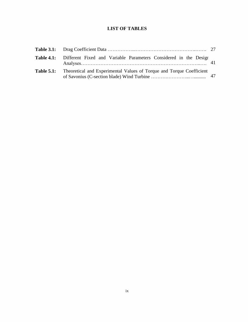
LIST OF TABLES
Table 3.1: Drag Coefficient Data ……………...……………………………….……. 27
Table 4.1: Different Fixed and Variable Parameters Considered in the Design
Analyses………………………………………………………………..…. 41
Table 5.1: Theoretical and Experimental Values of Torque and Torque Coefficient
of Savonius (C-section blade) Wind Turbine ……….…………..….......... 47
x
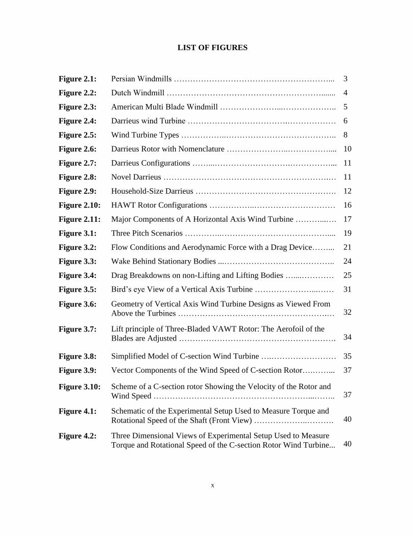
LIST OF FIGURES
Figure 2.1: Persian Windmills …………………………………………………... 3
Figure 2.2: Dutch Windmill …………………………………………………....... 4
Figure 2.3: American Multi Blade Windmill …………………...……………….. 5
Figure 2.4: Darrieus wind Turbine ……………………………….……………… 6
Figure 2.5: Wind Turbine Types ……………..………………………………….. 8
Figure 2.6: Darrieus Rotor with Nomenclature …………………..…………….... 10
Figure 2.7: Darrieus Configurations ……...……………………….……………... 11
Figure 2.8: Novel Darrieus …………………………………………………….… 11
Figure 2.9: Household-Size Darrieus ……………………………………………. 12
Figure 2.10: HAWT Rotor Configurations ……………..………………………… 16
Figure 2.11: Major Components of A Horizontal Axis Wind Turbine ………...…. 17
Figure 3.1: Three Pitch Scenarios …………..………………………………….... 19
Figure 3.2: Flow Conditions and Aerodynamic Force with a Drag Device……... 21
Figure 3.3: Wake Behind Stationary Bodies ...………………………………….. 24
Figure 3.4: Drag Breakdowns on non-Lifting and Lifting Bodies …....………… 25
Figure 3.5: Bird’s eye View of a Vertical Axis Turbine …………………...…… 31
Figure 3.6: Geometry of Vertical Axis Wind Turbine Designs as Viewed From
Above the Turbines ……………………………………………….… 32
Figure 3.7: Lift principle of Three-Bladed VAWT Rotor: The Aerofoil of the
Blades are Adjusted …………………………………………………. 34
Figure 3.8: Simplified Model of C-section Wind Turbine ….…………………… 35
Figure 3.9: Vector Components of the Wind Speed of C-section Rotor….……... 37
Figure 3.10: Scheme of a C-section rotor Showing the Velocity of the Rotor and
Wind Speed …………………………………………………...…….. 37
Figure 4.1: Schematic of the Experimental Setup Used to Measure Torque and
Rotational Speed of the Shaft (Front View) ………………..………. 40
Figure 4.2: Three Dimensional Views of Experimental Setup Used to Measure
Torque and Rotational Speed of the C-section Rotor Wind Turbine... 40

xi
Figure 4.3: Design Parameter of C-section Wind Turbine …………………….... 41
Figure 4.4: Anemometry Device ………………………………………………... 42
Figure 4.5: The Cut Section of a Worm Gearbox …………………………….… 42
Figure 4.6: Scheme of Electromechanical Dynamometer (Front and Right
Views) showing the Components of Electromechanical
Dynamometer ……….........................................................................
44
Figure 4.7: The Procedure for Calculating Mechanical Power of the C - section
Rotor ……………………………..…………………………………. 45
Figure 5.1: Scheme of a Savonius Rotor with L=0 mm ………………………… 46
Figure 5.2: Theoretical Predictions and Experimental Torque of Savonius Wind
Turbine Rotor ………………………………………..……………… 47
Figure 5.3: Theoretical Predictions and Experimental Torque Coefficient of
Savonius Wind Turbine Rotor ………………………..…………….. 48
Figure 5.4: Torque Versus Angle of Rotation for Different Diameter with Fixed
V = 4m/s , H = 40 cm and R= 28cm ………………….…………….. 49
Figure 5.5: Torque Versus Angle of Rotation for Different Diameter with Fixed
V = 6m/s , H = 40 cm and R= 28cm ………………….…………….. 50
Figure 5.6: Torque Versus Angle of Rotation for Different Diameter with Fixed
V = 10m/s , H = 40 cm and R= 28cm ………………….…………… 51
Figure 5.7: Torque Versus Angle of Rotation for Different Wind Speed with
Fixed D =10cm , H = 40 cm and R= 28cm …………….………….... 52
Figure 5.8: Torque Versus Angle of Rotation for Different Rotor Radius with a
Fixed d = 7cm, H = 40cm and V = 4m/s ……………….………….. 53
Figure 5.9: RPM Versus Wind Speed for Different Rotor Radius and Blade
Diameter with a fixed H = 30cm and N = 2 Blades ……..………… 54
Figure 5.10: RPM Versus Wind Speed for Different Rotor Radius and Blade
Diameter with a Fixed H = 30cm and N = 3 Blades ……..………… 55
Figure 5.11: RPM Versus Wind Speed for Different Rotor Radius and Blade
Diameter with a Fixed H = 30cm and N = 4 Blades ……….………. 56
Figure 5.12:
RPM Versus Wind Speed for Different Rotor Radius and Blade
Diameter with a Fixed H = 40cm and N = 2 Blades…………………
57
xii
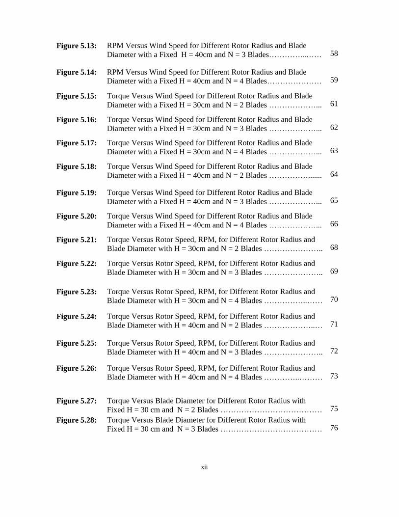
Figure 5.13: RPM Versus Wind Speed for Different Rotor Radius and Blade
Diameter with a Fixed H = 40cm and N = 3 Blades…………...…… 58
Figure 5.14: RPM Versus Wind Speed for Different Rotor Radius and Blade
Diameter with a Fixed H = 40cm and N = 4 Blades………………… 59
Figure 5.15: Torque Versus Wind Speed for Different Rotor Radius and Blade
Diameter with a Fixed H = 30cm and N = 2 Blades ………………... 61
Figure 5.16: Torque Versus Wind Speed for Different Rotor Radius and Blade
Diameter with a Fixed H = 30cm and N = 3 Blades ………………... 62
Figure 5.17: Torque Versus Wind Speed for Different Rotor Radius and Blade
Diameter with a Fixed H = 30cm and N = 4 Blades ………………... 63
Figure 5.18: Torque Versus Wind Speed for Different Rotor Radius and Blade
Diameter with a Fixed H = 40cm and N = 2 Blades ……………....... 64
Figure 5.19: Torque Versus Wind Speed for Different Rotor Radius and Blade
Diameter with a Fixed H = 40cm and N = 3 Blades ………………... 65
Figure 5.20: Torque Versus Wind Speed for Different Rotor Radius and Blade
Diameter with a Fixed H = 40cm and N = 4 Blades ………………... 66
Figure 5.21: Torque Versus Rotor Speed, RPM, for Different Rotor Radius and
Blade Diameter with H = 30cm and N = 2 Blades ………………….. 68
Figure 5.22: Torque Versus Rotor Speed, RPM, for Different Rotor Radius and
Blade Diameter with H = 30cm and N = 3 Blades ………………….. 69
Figure 5.23: Torque Versus Rotor Speed, RPM, for Different Rotor Radius and
Blade Diameter with H = 30cm and N = 4 Blades ……………..…… 70
Figure 5.24: Torque Versus Rotor Speed, RPM, for Different Rotor Radius and
Blade Diameter with H = 40cm and N = 2 Blades ………………..… 71
Figure 5.25: Torque Versus Rotor Speed, RPM, for Different Rotor Radius and
Blade Diameter with H = 40cm and N = 3 Blades ………………….. 72
Figure 5.26: Torque Versus Rotor Speed, RPM, for Different Rotor Radius and
Blade Diameter with H = 40cm and N = 4 Blades …………..……… 73
Figure 5.27:
Torque Versus Blade Diameter for Different Rotor Radius with
Fixed H = 30 cm and N = 2 Blades …………………………………
75
Figure 5.28: Torque Versus Blade Diameter for Different Rotor Radius with
Fixed H = 30 cm and N = 3 Blades ………………………………… 76
xiii
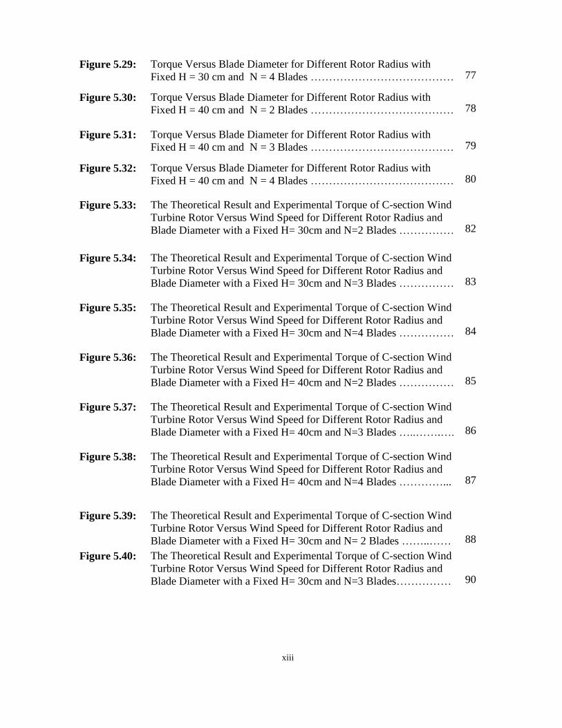
Figure 5.29: Torque Versus Blade Diameter for Different Rotor Radius with
Fixed H = 30 cm and N = 4 Blades ………………………………… 77
Figure 5.30: Torque Versus Blade Diameter for Different Rotor Radius with
Fixed H = 40 cm and N = 2 Blades ………………………………… 78
Figure 5.31: Torque Versus Blade Diameter for Different Rotor Radius with
Fixed H = 40 cm and N = 3 Blades ………………………………… 79
Figure 5.32: Torque Versus Blade Diameter for Different Rotor Radius with
Fixed H = 40 cm and N = 4 Blades ………………………………… 80
Figure 5.33: The Theoretical Result and Experimental Torque of C-section Wind
Turbine Rotor Versus Wind Speed for Different Rotor Radius and
Blade Diameter with a Fixed H= 30cm and N=2 Blades ……………
82
Figure 5.34: The Theoretical Result and Experimental Torque of C-section Wind
Turbine Rotor Versus Wind Speed for Different Rotor Radius and
Blade Diameter with a Fixed H= 30cm and N=3 Blades ……………
83
Figure 5.35: The Theoretical Result and Experimental Torque of C-section Wind
Turbine Rotor Versus Wind Speed for Different Rotor Radius and
Blade Diameter with a Fixed H= 30cm and N=4 Blades ……………
84
Figure 5.36: The Theoretical Result and Experimental Torque of C-section Wind
Turbine Rotor Versus Wind Speed for Different Rotor Radius and
Blade Diameter with a Fixed H= 40cm and N=2 Blades ……………
85
Figure 5.37: The Theoretical Result and Experimental Torque of C-section Wind
Turbine Rotor Versus Wind Speed for Different Rotor Radius and
Blade Diameter with a Fixed H= 40cm and N=3 Blades …..…….….
86
Figure 5.38: The Theoretical Result and Experimental Torque of C-section Wind
Turbine Rotor Versus Wind Speed for Different Rotor Radius and
Blade Diameter with a Fixed H= 40cm and N=4 Blades …………...
87
Figure 5.39:
The Theoretical Result and Experimental Torque of C-section Wind
Turbine Rotor Versus Wind Speed for Different Rotor Radius and
Blade Diameter with a Fixed H= 30cm and N= 2 Blades ……..……
88
Figure 5.40: The Theoretical Result and Experimental Torque of C-section Wind
Turbine Rotor Versus Wind Speed for Different Rotor Radius and
Blade Diameter with a Fixed H= 30cm and N=3 Blades……………
90

xiv
Figure 5.41: The Theoretical Result and Experimental Torque of C-section Wind
Turbine Rotor Versus Wind Speed for Different Rotor Radius and
Blade Diameter with a Fixed H= 30cm and N=4 Blades ……..…….
91
Figure 5.42: The Theoretical Result and Experimental Torque of C-section Wind
Turbine Rotor Versus Wind Speed for Different Rotor Radius and
Blade Diameter with a Fixed H= 40cm and N=2 Blades ……………
92
Figure 5.43: The Theoretical Result and Experimental Torque of C-section Wind
Turbine Rotor Versus Wind Speed for Different Rotor Radius and
Blade Diameter with a Fixed H= 40cm and N=3 Blades…………….
93
Figure 5.43: The Theoretical Result and Experimental Torque of C-section Wind
Turbine Rotor Versus Wind Speed for Different Rotor Radius and
Blade Diameter with a Fixed H= 40cm and N=4 Blades ……………
94
xv
LIST OF SYMBOLS AND ABBREVIATIONS USED
A Area [m2]
Aspect Ratio
Planform Area
B Wingspan is the Distance from one Wingtip to the Other Wingtip of
the Airplane
C Chord Length
Aerodynamic Drag Force [N]
Drag Coefficient
Drag Coefficient at Zero Lift
Induced Drag Coefficient
Friction Coefficient
Power Coefficient
Wind Velocity [m/s]
Speed of the Object Relative to the Fluid
Air Velocity [m/s]
Relative Velocity [m/s]
Power Capture [W]
Aerodynamic Pressure [Pa]
Reynolds Number
Air Density [kg/m3]
1
CHAPTER 1
INTRODUCTION
1.1 Background
Wind is called a renewable energy source because the wind will blow as long as the sun
shines. It has been harnessed for thousands of years. The wind’s kinetic energy can be
converted into other forms of energy, either electrical energy or mechanical energy. One of
the oldest uses of wind energy is transportation, people use it to sail ships, and farmers also
have been using wind energy to pump water, grind grain. More recently, it has been widely
used for special purposes in the world, such as generating electricity, and modern wind
turbines are the machines which are extremely efficient converting the wind energy into
electricity. The existing technology can offer different power ratings from a few kilowatts to
several megawatts.
The wind turbine is one the oldest know the method used to extract energy from the natural
sources (wind in this case). With the changing weather and wind speed, it is not possible to
produce high constant power from the wind turbine, but a small scale wind turbine can use
for small appliance at home.
A wind turbine is a device that extracts kinetic energy from the wind and converts it into
mechanical energy. Therefore wind turbine power production depends on the interaction
between the rotor and the wind. So the major aspects of wind turbine performance like power
output and loads are determined by the aerodynamic forces generated by the wind.
There are two types of wind turbines, namely horizontal-axis wind turbine (and vertical-axis
wind turbine. The vertical axis wind turbine has many advantages, such as low cost, simple-
structured blades, convenient installation and maintenance, and the ability to utilize wind
from all directions without the need of a steering mechanism.
The main aim of the research is to design a small C-section vertical axis wind turbine that
can generate electricity for home appliances. The thought of designing directs us to look into
the various aspects such as manufacturing, noise, and cost.

2
This research presents a theoretical and experimental study into the aerodynamics and
performance of small scale C-section vertical axis wind turbines and describes the effect of
some design parameters including wind speed, number of blades, and blade size and rotor
diameter on the performance of them. Considerable improvements in the understanding of
vertical axis wind turbine can be achieved through the use of theoretical study based on
velocity analysis and experimental measurements.
1.2 Aim of Thesis
The main aims of the research are outlined below:
1. To investigate the aerodynamic effects on the performance of C-section blade wind
turbine converting the wind energy to mechanical energy to overcome load applied to
the rotating main shaft.
2. To examine the effect of blade size and blade number of C-section on the rotational
speed, torque or mechanical power.
3. To compare the theoretical results based on the velocity analysis with experimental
data to obtain the absolute error between them.
1.3 Outline of Thesis
In chapter 2, briefly the types of wind turbines and characteristics of them are discussed in
details. A literature review of the performance of vertical turbine is presented in chapter 3
including previous attempts to improve the performance of the turbine. The methodology and
all the results of the experiments are presented in chapter 4 and 5 for vertical axis C-section
blade wind turbine, followed by a comparison between the theoretical data with experimental
data of vertical axis C-section blade wind turbine. The thesis ends with conclusions and
suggestions for future work in chapter 6.
3
CHAPTER 2
WIND TURBINES
The wind turbine can be classified according to the turbine generator configuration, airflow
path relative to the turbine rotor, turbine capacity, the generator-driving pattern, the power
supply mode and the location of turbine installation.
2.1 Brief History of Wind Power
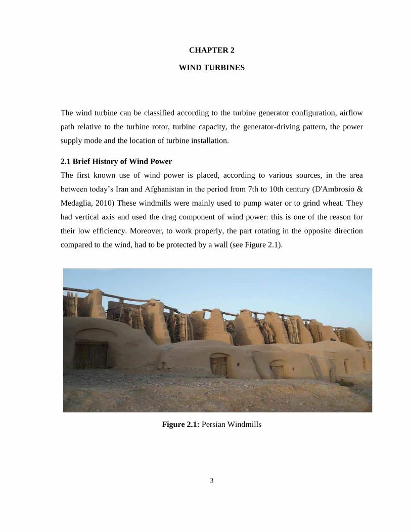
The first known use of wind power is placed, according to various sources, in the area
between today’s Iran and Afghanistan in the period from 7th to 10th century (D'Ambrosio &
Medaglia, 2010) These windmills were mainly used to pump water or to grind wheat. They
had vertical axis and used the drag component of wind power: this is one of the reason for
their low efficiency. Moreover, to work properly, the part rotating in the opposite direction
compared to the wind, had to be protected by a wall (see Figure 2.1).
Figure 2.1: Persian Windmills

4
Obviously, devices of this type can be used only in places with a main wind direction,
because there is no way to follow the variations.
The first windmills built in Europe and inspired by the Middle Eastern ones had the same
problem, but they used a horizontal axis. So they substitute the drag with the lift force,
making their inventors also the unaware discoverer of aerodynamics.
During the following centuries, many modifies were applied for the use in areas where the
wind direction varies a lot: the best examples are of course the Dutch windmills, used to
drain the water in the lands taken from the sea with the dams, could be oriented in wind
direction in order to increase the efficiency as shown in Figure 2.2.
Figure 2.2: Dutch Windmill
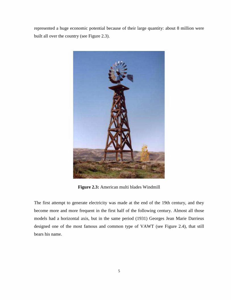
The wind turbines used in the USA during the 19th century and until the ’30 of the 20th
century were mainly used for irrigation. They had a high number of steel-made blades and
5
represented a huge economic potential because of their large quantity: about 8 million were
built all over the country (see Figure 2.3).
Figure 2.3: American multi blades Windmill
The first attempt to generate electricity was made at the end of the 19th century, and they
become more and more frequent in the first half of the following century. Almost all those
models had a horizontal axis, but in the same period (1931) Georges Jean Marie Darrieus
designed one of the most famous and common type of VAWT (see Figure 2.4), that still
bears his name.
6
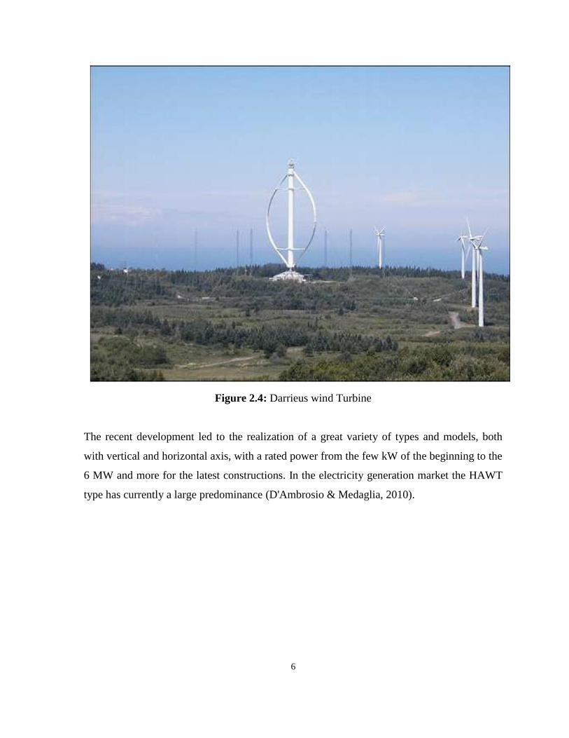
Figure 2.4: Darrieus wind Turbine
The recent development led to the realization of a great variety of types and models, both
with vertical and horizontal axis, with a rated power from the few kW of the beginning to the
6 MW and more for the latest constructions. In the electricity generation market the HAWT
type has currently a large predominance (D'Ambrosio & Medaglia, 2010).
7
2.2 Horizontal-Axis and Vertical-Axis Wind Turbines
When considering the configuration of the rotating axis of rotor blades, modern wind
turbines can be classified into horizontal-axis and vertical axis turbines.
Most commercial wind turbines today belong to the horizontal-axis type, in which the
rotating axes of the blades are parallel to the wind stream. The advantages of this type of
wind turbines include the high turbine efficiency, high power density, low cut-in wind speed
and low cost per unit power output.
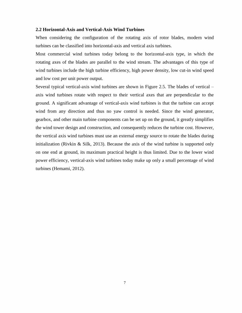
Several typical vertical-axis wind turbines are shown in Figure 2.5. The blades of vertical –
axis wind turbines rotate with respect to their vertical axes that are perpendicular to the
ground. A significant advantage of vertical-axis wind turbines is that the turbine can accept
wind from any direction and thus no yaw control is needed. Since the wind generator,
gearbox, and other main turbine components can be set up on the ground, it greatly simplifies
the wind tower design and construction, and consequently reduces the turbine cost. However,
the vertical axis wind turbines must use an external energy source to rotate the blades during
initialization (Rivkin & Silk, 2013). Because the axis of the wind turbine is supported only
on one end at ground, its maximum practical height is thus limited. Due to the lower wind
power efficiency, vertical-axis wind turbines today make up only a small percentage of wind
turbines (Hemami, 2012).
8
Figure 2.5: Wind turbine types
2.2.1 Vertical Axis Wind Turbines (VAWT)
The principle advantage of modern vertical axis wind machine over their conventional
counterpart is that VAWT are omnidirection. They accept the wind from any direction. This
simplifies their design and eliminates the problem imposed by gyroscopic forces on the rotor
of conventional machine as the turbine tracks the wind. The vertical axis of rotation also
permits mounting the generator and drive train at ground level as shown in Figure 2.5.
Vertical-axis turbines can be divided into two major groups:
9
Those that use aerodynamic drag to extract power from wind.
Those that use the lift.
The simplest configuration uses two or more straight blades attached to the ends of the
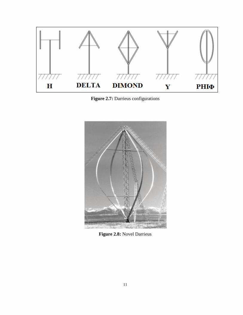
horizontal cross-arm. This gives the rotor the shape of the large H (see Figure 2.7).
Unfortunately, this configuration permits centrifugal forces induce server bending stress on
the blades at their point of attachment.
During the 1920s French inventor D.G.M. Darrieus patented a wind machine that cleverly
dealt with this limitation. Instead of using straight blades, he attached curved blades to the
rotor. When the turbine was operating, the curved blades would take on the form of a
spinning rope held at both ends. This troposkein shape directs centrifugal forces through the
blade's length toward the points of attachment, thus creating tension, rather than bending, in
the blades. Because materials are stronger in tension than in bending, the blades can be
lighter for the same overall strength and operate at higher speeds than straight blades.
Although the phi (Φ) or Eggbeater configuration is the most common, Darrieus conceived
several other versions, including Delta, Diamond, and Y as shown in Figure 2.7. All have
been tried at one time or another (see Figure 2.6, Darrieus configurations). Some have linked
the phi-configuration about a vertical axis.

10
Figure 2.6: Darrieus rotor with nomenclature
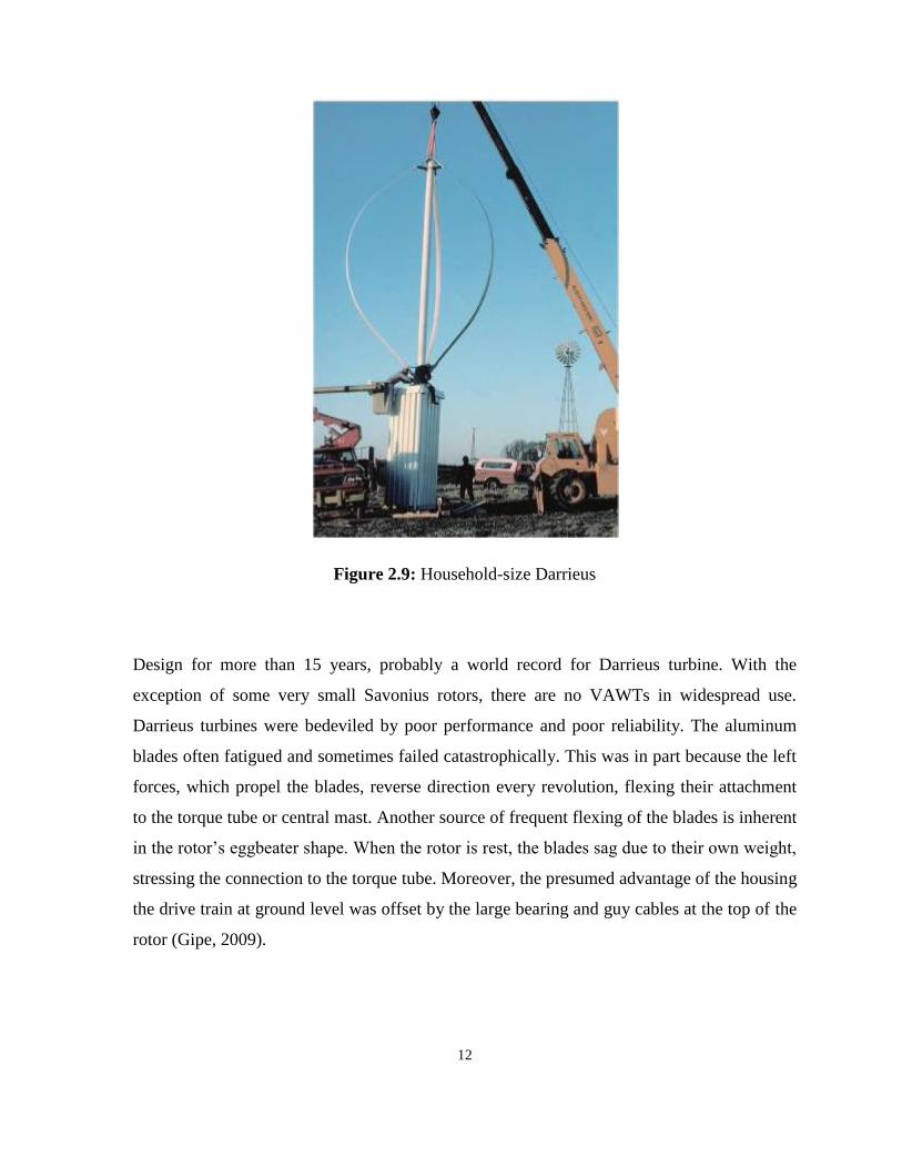
The Darrieus’s concept eventually faded into obscurity. Canada’s National Research Council
reinvented the design in the mid-1960s, and subsequently Canadian wind research focused on
Darrieus turbines (see Figure 2.8). In the United States, Sandia National Laboratories have
also pursued the technology. Several terms in Europe and North America attempted to
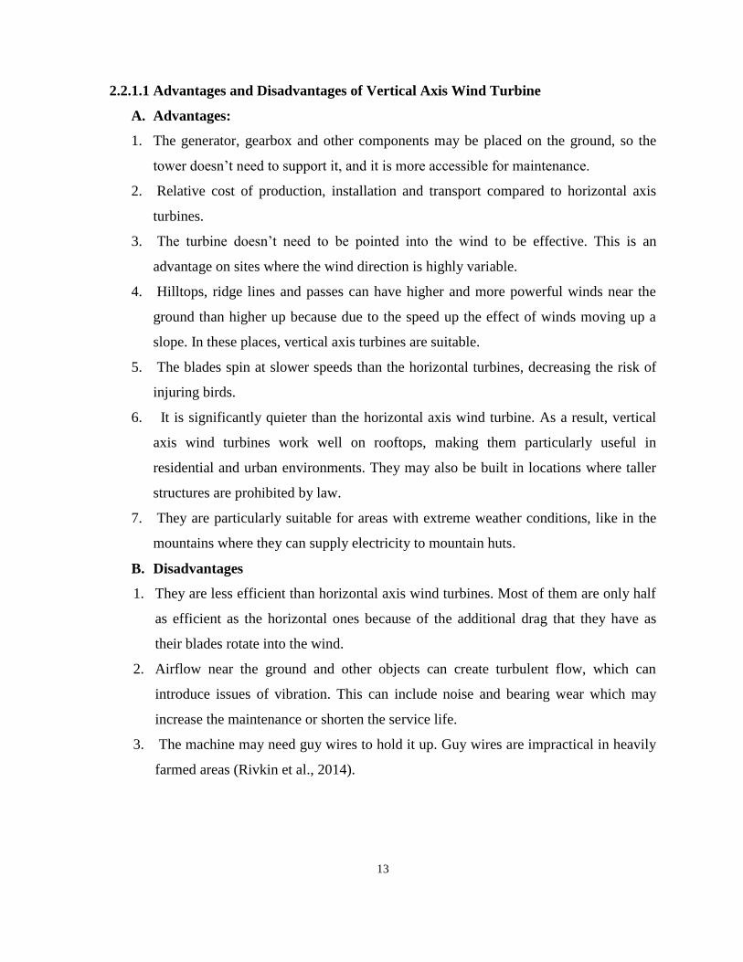
commercialize Darrieus technology, but had little lasting success as shown in Figure 2.9.
Work on the technology has practically ceased, and there are few Darrieus turbines still in
service. Carl Brothers operate one of the last of the breed in Canada’s Atlantic, Wind Test
Site on Prince Edward Island. The test site has operated at 35 kW DAF-Indal.
11
Figure 2.7: Darrieus configurations
Figure 2.8: Novel Darrieus
12
Figure 2.9: Household-size Darrieus
Design for more than 15 years, probably a world record for Darrieus turbine. With the
exception of some very small Savonius rotors, there are no VAWTs in widespread use.
Darrieus turbines were bedeviled by poor performance and poor reliability. The aluminum
blades often fatigued and sometimes failed catastrophically. This was in part because the left
forces, which propel the blades, reverse direction every revolution, flexing their attachment
to the torque tube or central mast. Another source of frequent flexing of the blades is inherent
in the rotor’s eggbeater shape. When the rotor is rest, the blades sag due to their own weight,
stressing the connection to the torque tube. Moreover, the presumed advantage of the housing
the drive train at ground level was offset by the large bearing and guy cables at the top of the
rotor (Gipe, 2009).
13
2.2.1.1 Advantages and Disadvantages of Vertical Axis Wind Turbine
A. Advantages:
1. The generator, gearbox and other components may be placed on the ground, so the
tower doesn’t need to support it, and it is more accessible for maintenance.
2. Relative cost of production, installation and transport compared to horizontal axis
turbines.
3. The turbine doesn’t need to be pointed into the wind to be effective. This is an
advantage on sites where the wind direction is highly variable.
4. Hilltops, ridge lines and passes can have higher and more powerful winds near the
ground than higher up because due to the speed up the effect of winds moving up a
slope. In these places, vertical axis turbines are suitable.
5. The blades spin at slower speeds than the horizontal turbines, decreasing the risk of
injuring birds.
6. It is significantly quieter than the horizontal axis wind turbine. As a result, vertical
axis wind turbines work well on rooftops, making them particularly useful in
residential and urban environments. They may also be built in locations where taller
structures are prohibited by law.
7. They are particularly suitable for areas with extreme weather conditions, like in the
mountains where they can supply electricity to mountain huts.
B. Disadvantages
1. They are less efficient than horizontal axis wind turbines. Most of them are only half
as efficient as the horizontal ones because of the additional drag that they have as
their blades rotate into the wind.
2. Airflow near the ground and other objects can create turbulent flow, which can
introduce issues of vibration. This can include noise and bearing wear which may
increase the maintenance or shorten the service life.
3. The machine may need guy wires to hold it up. Guy wires are impractical in heavily
farmed areas (Rivkin et al., 2014).
14
2.2.2 Horizontal Axis Wind Turbine (HAWT)
Horizontal axis wind turbines usually have three blades that operate upwind (toward the
wind). The main rotor shaft and electrical generator are located at the top of the tower and
face upwind. Many small HAWTs use a wind vane (weather vane) and large turbines use
wind sensors (with a servo motor). Most horizontal axis turbines have a gearbox to increase
the rotational speed of the generator well above the rotational speed of the blades. The
turbine must point upwind because the structure, it produces turbulence behind it. To prevent
damage, the turbine blades of a HAWT are usually very sturdy and positioned as far away
from the tower as possible (sometimes tilted forward at the lower arc).
Though usually able to produce more energy than their counterparts (VAWT), horizontal
axis wind turbines employ automated systems that readjust the orientation of the nacelle such
that the rotor remain perpendicular to oncoming wind. Downwind HAWTs have been
manufactured to reduce wind realignment and decrees blade damage. These HAWTs have
flexible blades, because there is no risk of tower interference, but the flexible blades can
reduce the swept area. Wind turbulence causes fatigue failure is most downwind turbines.
Thus, to reap the most benefits, most horizontal axis wind turbines tend to be upwind rather
than downwind.
Most modern wind turbines on wind farm are horizontal axis with three blades and face
upwind. These highly efficient and highly reliable (low torque ripple) commercial turbines
reach a high top speed of over 320km/h. Blades the range from 20 to 40 plus meters rotate at
10-22 revolutions per minutes. Knowing this information is helpful for finding tip-speed ratio
(TSR). TSR is the ratio between the blade tip speed and the current wind speed in a given
moment. If the tip speed is exactly the same as the wind speed, TSR is 1. TSR is related to
efficiency. Higher tip speeds result in higher noise levels and due to large centripetal forces
(it is a force that makes a body follows a curved path. Its direction is always orthogonal to
the motion of the body and towards the fixed point of the instantaneous center of curvature of
the path), the need for stronger blades. The tubular steel towers of these turbines vary in
height from 60 to 90 meters. Gearboxes are usually used to adjust the speed of the generator;
otherwise annular generators (direct drive) are used, which negates the necessity of the
gearbox. Most of these turbines are variable speed types that use solid-state electronic power
converters to more efficiently collect energy from the wind (Rivkin et al., 2014).
15
2.2.2.1 Types of HAWT
There are two types of horizontal axis wind turbines
A. Horizontal upwind: the generator shaft is positioned horizontally and the wind hits the
blade before the tower. Turbine blades are made stiff to prevent the blades from being
pushed into the tower by high winds, and the blades are placed at a considerable
distance in front of the tower and are sometimes tilted up a small amount.
Horizontal downwind: the generator shaft is positioned horizontally and the wind hits the
tower first and then the blade. Horizontal downwind does not need an additional mechanism
for keeping it in line with the end, and in high winds the blades can be allowed to bend,
which reduces their swept area and thus their wind resistance. The horizontal downwind
turbine is also free of turbulence problems.
2.2.2.2 Advantages and Disadvantages of Horizontal Axis Wind Turbine
A. Horizontal Axis Wind Turbine Advantages:
The advantages of using this type of turbine are following
Their tall towers allow wind turbine blades to access strong wind. If we increase the
height of wind turbine blades to every 10 meters, we will get 20% more speed and
34% more power output.
The efficiency of this type of wind turbine is more as compare to vertical axis wind
turbine because blades are perpendicular to wind. With this direction, they have more
capability to receive wind impact.
These turbines have variable blade pitch. By this behavior, blades get the optimum
angle of attack which allows the blades to adjust it for greater control to get
maximum wind energy.
B. Horizontal Axis Wind Turbine Disadvantages:
Because of getting high attitude, tower needs massive construction to support heavy blades
and its other components like gearbox and electricity. Tower height makes wind turbine
visible across many areas which will create disturbance to view the landscape. Horizontal
axis wind turbines designed on downwind failed due to fatigue and failure when turbine
blades pass through the shadow of tower. Horizontal axis wind turbines need yaw control
mechanism for turning their blades to get maximum wind energy.
16
Horizontal axis wind turbines need yawing or braking devices when the speed of wind is
enough. If such type of situations where we don’t stop wind turbines it can destroy itself also.
Due to the movements of turbine blades, cyclic stresses generate because one of the blades of
turbine faces minimum wind energy and other at the same time faces maximum which will
create twists and crack the blade quickly (Casper, 2007).
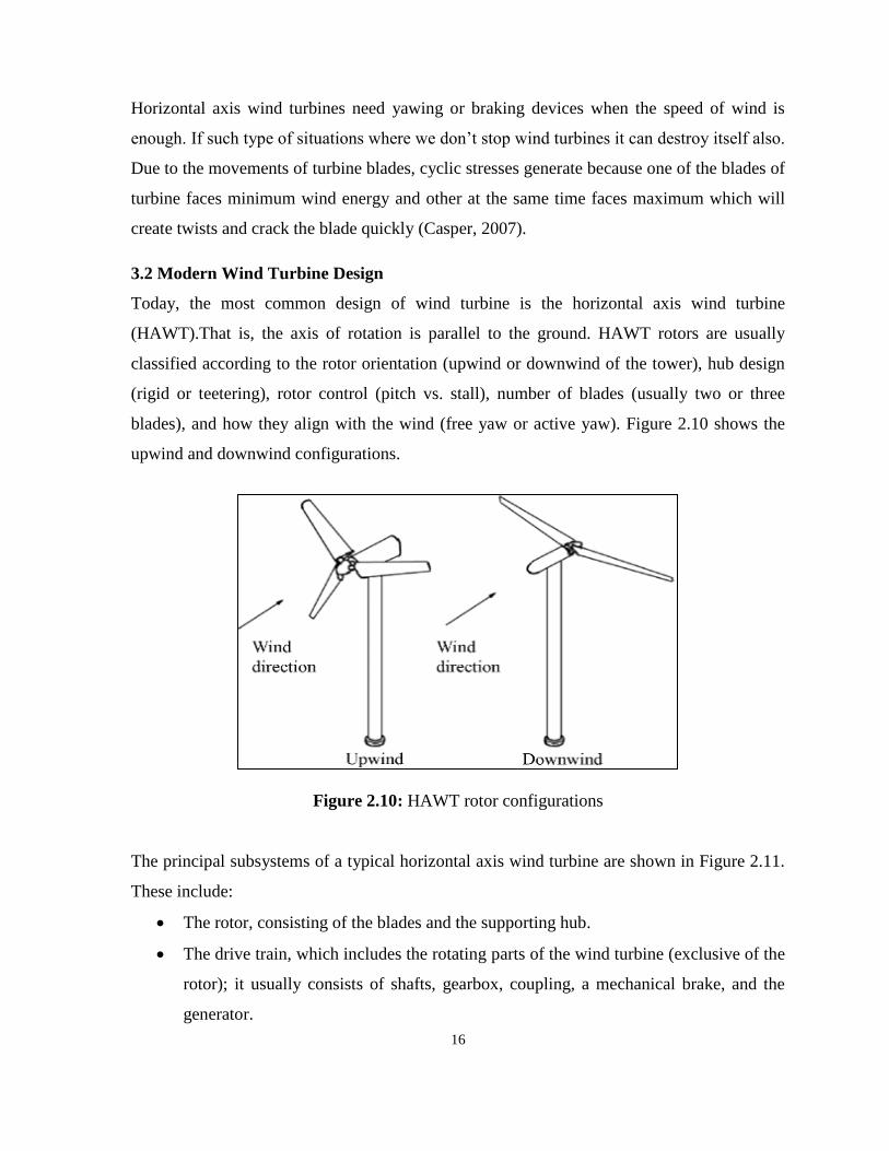
3.2 Modern Wind Turbine Design
Today, the most common design of wind turbine is the horizontal axis wind turbine
(HAWT).That is, the axis of rotation is parallel to the ground. HAWT rotors are usually
classified according to the rotor orientation (upwind or downwind of the tower), hub design
(rigid or teetering), rotor control (pitch vs. stall), number of blades (usually two or three
blades), and how they align with the wind (free yaw or active yaw). Figure 2.10 shows the
upwind and downwind configurations.
Figure 2.10: HAWT rotor configurations
The principal subsystems of a typical horizontal axis wind turbine are shown in Figure 2.11.
These include:
The rotor, consisting of the blades and the supporting hub.
The drive train, which includes the rotating parts of the wind turbine (exclusive of the
rotor); it usually consists of shafts, gearbox, coupling, a mechanical brake, and the
generator.

17
The nacelle and main frame, including wind turbine housing, bedplate, and the yaw
system the tower and the foundation.
The machine controls the balance of the electrical system, including cables,
switchgear, transformers, and possibly electronic power converters (Manwell et al.,
2014).
Figure 2.11: Major components of a horizontal axis wind turbine
The picture above shows the various components of a Horizontal Axis Wind Turbine
(HAWT). The three most important parts are the rotor, the gear box, and the generator.
Rotor blades: The blades are basically the sails of the system; in their simplest
form, they act as barriers to the wind (more modern blade designs go beyond the
barrier method). When the wind forces the blades to move, it has transferred
some of its energy to the rotor.
18
Shaft: The wind-turbine shaft is connected to the center of the rotor. When the
rotor spins, the shaft spins as well. In this way, the rotor transfers its mechanical,
rotational energy to the shaft, which enters an electrical generator on the other
end.
Generator: At its most basic, a generator is a pretty simple device. It uses the
properties of electromagnetic induction to produce an electrical voltage - a
difference in electrical charge. Voltage is essentially electrical pressure - it is the
force that moves electricity, or electrical current, from one point to another. So
generating voltage is in effect generating current. A simple generator consists of
magnets and a conductor. The conductor is typically a coiled wire. Inside the
generator, the shaft connects to an assembly of permanent magnets that surrounds
the coil of wire. In electromagnetic induction, if you have a conductor surrounded
by magnets, and one of those parts is rotated relative to the other, it induces a
voltage in the conductor. When the rotor spins the shaft, the shaft spins the
assembly of magnets, generating voltage in the coil of wire. That voltage drives,
electrical current (typically alternating current, or AC power) out through power
lines for distribution (Hau, 2006).

19
CHAPTER 3
VERTICAL AXIS WIND TURBINE AND AERODYNAMIC FORCE
3.1. Capturing The Wind
The wind turbine rotor assembly is designed to convert mechanical power from the wind into
an electrical output. The rotor assembly includes the hub, spinner, blades and all the enclosed
systems used to control blade pitch. The electric output process will remain efficient only
through diligence, proactive service and a maintenance plan. A good rotor assembly,
maintenance plan should include inspections to ensure blade structural integrity along with
activities to maintain clean, smooth exterior surfaces and the aerodynamic profile. Wind
turbine blades are designed to enable the airflow around them to create reaction forces
perpendicular and parallel to the oncoming wind. The reaction force perpendicular to
oncoming wind is considered drag. The amount of lift and drag created by an object are
function of shape, surface area and wind velocity. A thin flat panel positioned or pitched
perpendicular to the wind will create drag without any lift force. The same flat panel pitched
parallel to the wind will create a small amount of the drag but no lift. To create both lift and
drag, the panel must be pitched at an angle to the oncoming wind. Figure 3.1 shows examples
of these pitch scenarios. Because these forces result from the interaction of an object within a
moving fluid (wind), they are considered aerodynamic forces (Kilcollins, 2013).
Figure 3.1: Three pitch scenarios
20
3.1.1 Aerodynamic Forces
The force from the wind on a place is called aerodynamic force. We referred to the two
aerodynamic force component as lift and drag; any force can be broken into two components.
Here the lift force and drag force are the two components of the aerodynamic force on the
plate under consideration. There two components are perpendicular to each other; that is,
they make an angle of 90° with each other as shown in Figure 3.1. Recall that the force
exerted on a surface (the plate surface) is always the product of the area and pressure on the
surface (Hemami, 2012).
Aerodynamic force is a function of aerodynamic pressure created by wind impacting the
surface of the object. This force may be calculated using the aerodynamic pressure caused by
wind impacting the blade and the blade exposed surface area. Aerodynamic pressure (PA) is a
function of the adjusted air density and the wind velocity squared ( ( ⁄ ) ).
Adjusted air density refers to the change in density because of elevation and temperature.
Increasing elevation from elevation from sea level and ambient temperature, above or below
the standard temperature will change the air density and so will an increase the temperature.
Decreasing the air temperature will increase the air density value. This is why cold air
blowing in the winter will have more available power than the same velocity wind on a hot
summer day (Kilcollins, 2013).
3.2. Drag Devices
The simplest type of wind energy conversion can be achieved by means of pure drag surface
(Figure 3.2). The air impinges on the surface A with wind velocity, vw, the power capture, P,
of which can be calculated from the aerodynamic drag, FD, the area A and the rotor velocity
or rotor speed, vr with which it moves
( )

21
Figure 3.2: Flow conditions and aerodynamic force with a drag device
The relative velocity , which effectively impinges on the drag area, is decisive
from its aerodynamic drag, using common aerodynamic drag coefficient,CD, the aerodynamic
drag can be expressed as :
( )
( )
The resultant power is
( )
( )
If the power is expressed again in terms of the power contained in the free stream airflow, the
following power coefficient is obtained (Hau, 2006).:
( )
( )

22
Drag force can be defined as in fluid mechanics, the force which exerted on the solid object
in the upstream direction of the relative flow velocity (Hutchinson, 2016).
Drag force depends on flow velocity and it decreases the fluid velocity (French & Ebison,
1986). Therefore, drag force also called air resistance or fluid resistance.
3.3. Drag Force
Drag is the force experienced by an object that is in line with the flow of any fluid such as the
air stream. The drag force is developed by obstructing the flowing wind and creating a
turbulence. Drag devices are simple wind machines that use flat or curved blades to catch the
wind in the enclosed area to turn the rotor. Drag force depends on exposing a flat or curved
area on one side of a rotor to the wind while shielding the other, the resulting differential
drag force turns the rotor (Earnest, 2015).
The drag on an object in the wind, whether it is a tall building, tower or wind turbine is a
function of air density, the area intercepting the wind, the speed of the wind and
dimensionless coefficient that represents the object’s shape and its angle to the wind.
( )
where is drag force, ρ air density, A is the area intercepting the wind, V is the wind speed
and CD is the coefficient of the drag.
3.3.1 Types of Drag
As already mentioned, the drag is the resistive force encountered by body when it is moving
through a fluid or when the fluid flows past a solid body. In both cases, in order to maintain
steady motion, a force is the direction of relative motion has to be exerted. Thus, when the
submarine moves through water or an aero-plane flies through atmosphere, the vehicle has to
exert a forward force sufficient enough to balance the drag force. Drag force may be related
to the effect of boundary layer, flow separation and wake. The existence of viscosity for the
fluid is mainly responsible for causing drag on bodies.
The total drag may be separated into a number of items each contributing to the total. As first
step, it is divided into friction drag and pressure drag.
23
3.3.1.1 Friction Drag
Due to the viscous nature of fluid, the fluid motion tends to be rotational which gives rise to
velocity gradient in the thin boundary layer region. In the laminar boundary, since the
adjacent fluid layers move with different velocities, tangential shear stress is set up. In the
turbulent layer, since there is velocity fluctuation, additional shear stress is set up. These
shear stresses leads to the shear drag or friction drag, friction drag does not exist in a flow
assumed to be invisicde.
3.3.1.2 Pressure Drag
The drag force arising from the resolved components of the pressure on the boundary is the
pressure drag. The pressure drag may itself be considered as sum of the several distinct
items.
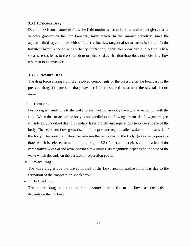
i. Form Drag
Form drag is mainly due to the wake formed behind anybody having relative motion with the
fluid. When the surface of the body is not parallel to the flowing stream, the flow pattern gets
considerably modified due to boundary layer growth and separations from the surface of the
body. The separated flow gives rise to a low pressure region called wake on the rear side of
the body. The pressure difference between the two sides of the body gives rise to pressure
drag, which is referred to as form drag. Figure 3.3 (a), (b) and (c) gives an indication of the
comparative width of the wake behind a few bodies. Its magnitude depends on the size of the
wake which depends on the position of separation points
ii. Wave Drag
The wave drag is due the waves formed in the flow, incompressible flow, it is due to the
formation of the compression shock wave.
iii. Induced drag
The induced drag is due to the trailing vortex formed due to the flow past the body, it
depends on the lift force.
24
Figure 3.3: Wake behind stationary bodies
If the wave drag and induced drag are neglected, then the total drag is essentially the skin
friction drag and the form drag (Balachandran, n.d.).
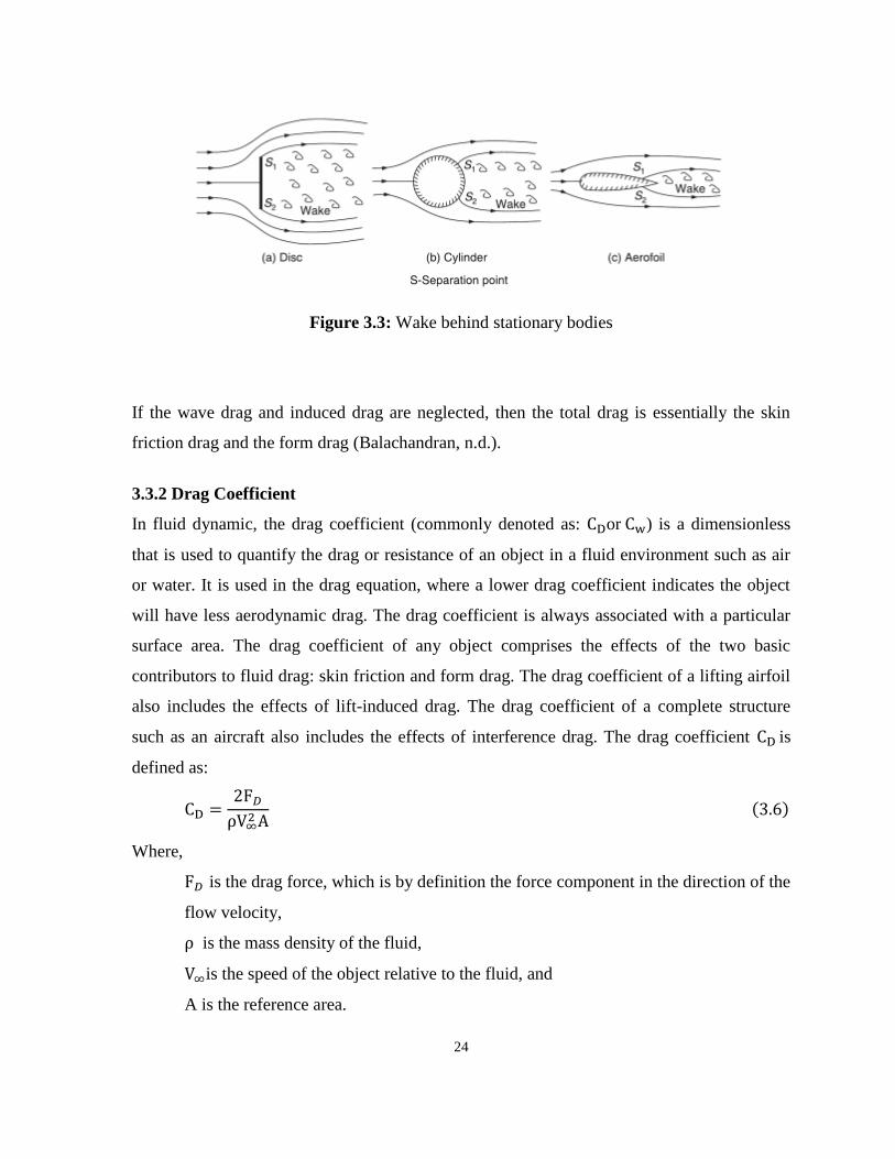
3.3.2 Drag Coefficient
In fluid dynamic, the drag coefficient (commonly denoted as: or ) is a dimensionless
that is used to quantify the drag or resistance of an object in a fluid environment such as air
or water. It is used in the drag equation, where a lower drag coefficient indicates the object
will have less aerodynamic drag. The drag coefficient is always associated with a particular
surface area. The drag coefficient of any object comprises the effects of the two basic
contributors to fluid drag: skin friction and form drag. The drag coefficient of a lifting airfoil
also includes the effects of lift-induced drag. The drag coefficient of a complete structure
such as an aircraft also includes the effects of interference drag. The drag coefficient is
defined as:
ρ
( )
Where,
is the drag force, which is by definition the force component in the direction of the
flow velocity,
ρ is the mass density of the fluid,
is the speed of the object relative to the fluid, and
A is the reference area.

25
Drag on airfoils arises from viscous and pressure forces. Viscous drag or Skin friction
changes with Reynolds number and arises from the interaction between the fluid and the skin
of the body but only slightly with angle of attack. These relationships and some commonly
used terminology are illustrated in Figure 3.4.
A useful approximation to drag polar for complete aircraft may be obtained by adding the
induced drag or vortex drag, or sometimes drag due to lift, is a drag force that occurs
whenever a moving object redirects the airflow coming at it to the drag at zero lift. The drag
at any lift coefficient is obtained from
( )
Where,
: drag coefficient at zero lift
: induced drag coefficient
: Aspect ratio
b: wingspan or is the distance from one wingtip to the other wingtip of the airplane
: Planform area
c: chord length.
Figure 3.4: Drag breakdowns on nonlifting and lifting bodies
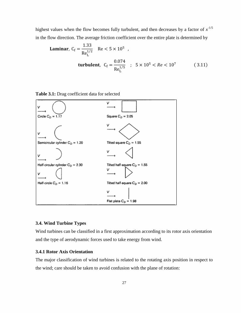
The drag coefficient for all objects with sharp edge is essentially independent of Reynolds
number (for Re≥10000) because the separation points and therefore the size of the wake are
26
fixed by the geometry of the object. Drag coefficients for selected objects are given in table
3.1
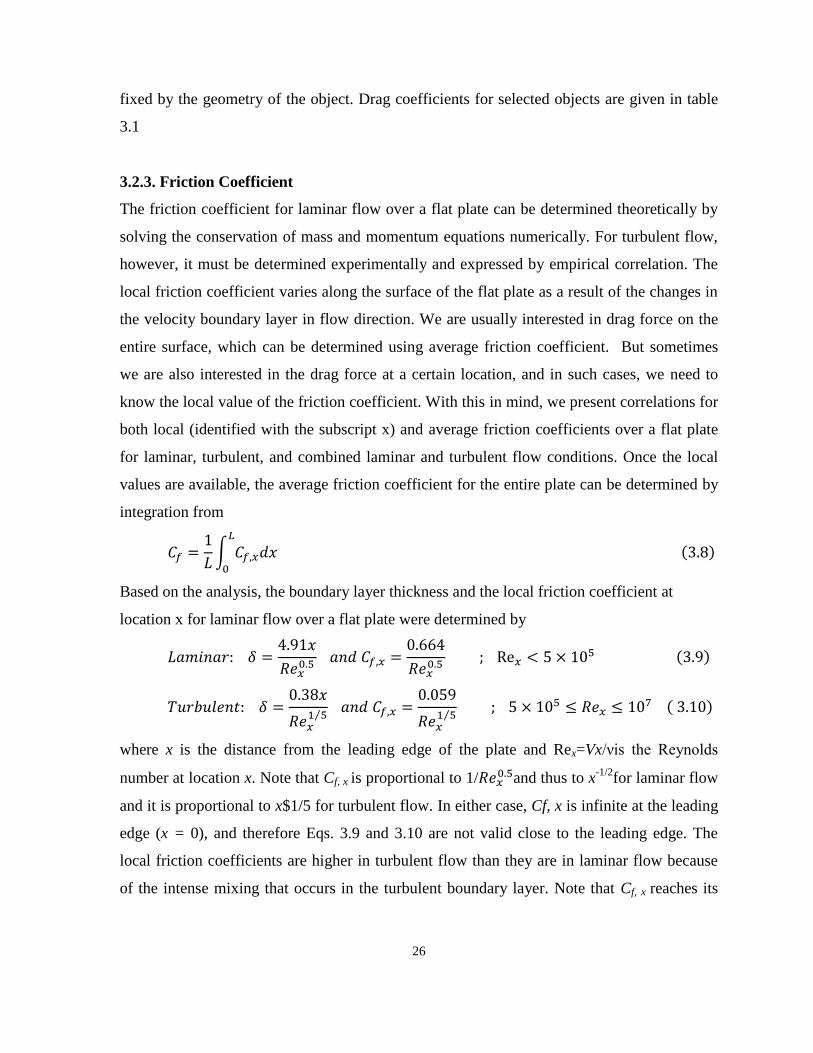
3.2.3. Friction Coefficient
The friction coefficient for laminar flow over a flat plate can be determined theoretically by
solving the conservation of mass and momentum equations numerically. For turbulent flow,
however, it must be determined experimentally and expressed by empirical correlation. The
local friction coefficient varies along the surface of the flat plate as a result of the changes in
the velocity boundary layer in flow direction. We are usually interested in drag force on the
entire surface, which can be determined using average friction coefficient. But sometimes
we are also interested in the drag force at a certain location, and in such cases, we need to
know the local value of the friction coefficient. With this in mind, we present correlations for
both local (identified with the subscript x) and average friction coefficients over a flat plate
for laminar, turbulent, and combined laminar and turbulent flow conditions. Once the local
values are available, the average friction coefficient for the entire plate can be determined by
integration from
∫
( )
Based on the analysis, the boundary layer thickness and the local friction coefficient at
location x for laminar flow over a flat plate were determined by
( )
⁄
⁄
( )
where x is the distance from the leading edge of the plate and Rex=Vx/νis the Reynolds
number at location x. Note that Cf, x is proportional to 1/ and thus to x
-1/2for laminar flow
and it is proportional to x$1/5 for turbulent flow. In either case, Cf, x is infinite at the leading
edge (x = 0), and therefore Eqs. 3.9 and 3.10 are not valid close to the leading edge. The
local friction coefficients are higher in turbulent flow than they are in laminar flow because
of the intense mixing that occurs in the turbulent boundary layer. Note that Cf, x reaches its
27
highest values when the flow becomes fully turbulent, and then decreases by a factor of x-1/5
in the flow direction. The average friction coefficient over the entire plate is determined by
⁄
⁄
( )
Table 3.1: Drag coefficient data for selected
3.4. Wind Turbine Types
Wind turbines can be classified in a first approximation according to its rotor axis orientation
and the type of aerodynamic forces used to take energy from wind.
3.4.1 Rotor Axis Orientation
The major classification of wind turbines is related to the rotating axis position in respect to
the wind; care should be taken to avoid confusion with the plane of rotation:

28
Horizontal Axis Wind Turbines (HAWT): the rotational axis of this turbine must be
oriented parallel to the wind in order to produce power. Numerous sources claim a
major efficiency per same swept area and the majority of wind turbines are of this
type.
Vertical Axis Wind Turbines (VAWT): the rotational axis is perpendicular to the
wind direction or the mounting surface. The main advantage is that the generator is
on ground level so they are more accessible and they don’t need a yaw system.
Because of its proximity to the ground, wind speeds available are lower. One
interesting advantage of VAWTs is that the blades can have a constant shape along
their length and, unlike HAWTs, there is no need in twisting the blade as every
section of the blade is subjected to the same wind speed. This allows an easier design,
fabrication and replication of the blade which can influence in a cost reduction and is
one of the main reasons to design the wind turbine with this rotor configuration
(Graebel, 2001).
3.4.2. Lift or Drag Type
There are two ways of extracting the energy from the wind depending on the main
aerodynamic forces used:
The drag type takes less energy from the wind, but has a higher torque and is used for
mechanical applications as pumping water. The most representative models of drag-
type VAWTs is the Savonius.
The lift type uses an aerodynamic airfoil to create a lift force, they can move quicker
than the wind flow. This kind of windmills is used for the generation of electricity.
The most representative models of a lift-type VAWT is the Darrieus turbine; its
blades have a troposkien shape which is appropriate for standing high centrifugal
forces.
3.5. Reviews on Three Blade Wind Turbine
Mohammed, 2013, carried out an experimental study using subsonic wind tunnel under low
wind speed. Also, he compared and investigated the performance of two and three blades of
Savonius wind turbine rotor. He concluded that increasing the number of blades will increase

29
the drag surfaces against the windair flow and causes it to increase the reverse torque and
leads to a decrease in the net torque working on the blades of a Savonius wind turbine.
Mashhadet al., 2013, studied experimentally and computationally the feasibility of improving
the performance of the three blades vertical-axis Savonius wind turbine with different
overlap ratios and without overlap under low-speed subsonic wind tunnel at different
Reynolds numbers. The results showed that lower Reynolds number gave better torque
coefficient variation with the increase of the angle of rotation for each model and Power
coefficient calculated from the numerical method shows that it is always increasing with the
increase of the tip speed ratio.
Wenehenubun et al., 2015, studied experimentally the effect of number of blades (2, 3 and 4
blades) on the performance of the model of the Savonius type wind turbine. The author
concludes that the number of blades influences the performance of wind turbine and
Savonius model with three blades has the best performance at high tip speed ratio.
Saha et al., 2008, discussed the aerodynamic performance of single-, two- and three-stage
Savonius rotor systems based on experiments that are carried out to optimize the different
parameters like number of stages, number of blades and geometry of the blade. And All the
experiments had been conducted at different wind speed. The results showed a twisted
geometry blade profile had better performance as compared to the semicircular blade
geometry, the two-stage Savonius rotor had a better power coefficient as compared to the
single- and three-stage rotors.
Saha and Rajkumar, 2006, tested the twisted blade in a three bladed Savonius wind rotor in a
low speed wind tunnel. The experimental results showed that the potential of the twisted
bladed rotor in terms of smooth running, higher efficiency and self-starting capability as
compared to that of the conventional bladed rotor.
M. Jamil et al., 2013, presented Experimental Study the performance of a Combined Three
Bucket H-Rotor with Savonius Wind Turbine (H-rotor WT with DUW200 airfoils). The
authors concluded that Combining both Savonius and H-rotor with each other makes an
efficient wind turbine which has the better self-starting ability besides higher power
coefficient.
K.K. Sharma et al., 2013, presented performance measurement of three bladed combined
Darrieus- Savonius rotor with Darrieus mounted on top of Savonius rotor. The authors

30
concluded that an optimum TSR at which the performance coefficients are the highest and an
optimum overlap at which the performance coefficients are the highest.
Gupta and Biswas, 2011, studied numerically the performance of a combined three-bucket
Savonius and three-bladed Darrieus turbine and measured the aerodynamic coefficients with
respect to angle of attack for various tip speed ratios. The authors concluded that the power
augmentation of the combined turbine occurred for low overlap in Savonius turbine due to
high aerodynamic lift-to-drag coefficient of the Savonius turbine, caused by the increase of
dynamic pressure from bucket-vortex interactions on the concave face of the returning
bucket. And high value of overlap (20% onwards) caused vortex separations from the inner
edges of the bucket destabilizing the Coanda flow for which the aerodynamic coefficients
were lowered.
3.6 Vertical Axis Wind Turbine (VAWT)
In recent years vertical axis wind turbine arrays have been shown to produce more power per
unit land area than horizontal axis wind turbines, primarily due to the difference in spacing
requirements between the two turbine types (Kinzel, et al., 2012; Hau, 2006). While vertical
axis wind turbines (VAWTs) were the first type of wind turbine in existence.
horizontal axis wind turbines (HAWTs) quickly became the prevailing wind energy
converter due to their higher efficiency.
The result of this shift in focus is that horizontal axis wind turbines have gone through many
more years of technical development than their counterparts. Consequently, vertical axis
wind turbines have remained an immature technology (Sheldahl et al., 1977).
One significant difference between VAWTs and HAWTs is the method with which the
blades interact with the wind. HAWTs orientate their rotor blades perpendicular to the wind,
i.e. their power production depends on the angle between the wind direction and the rotor.
With proper alignment between wind direction and the rotor, the blades continuously
produce lift, which in turn keeps the rotor spinning.
In contrast, VAWTs are independent of wind direction. The blades must produce positive
torque throughout half of one rotation, while minimizing any negative impact on rotor
rotation as the blades are carried back upstream. This is due to the symmetry of the turbine as
laid out in Figure 3.5, where a VAWT is depicted from the side (a) and from above (b).
31
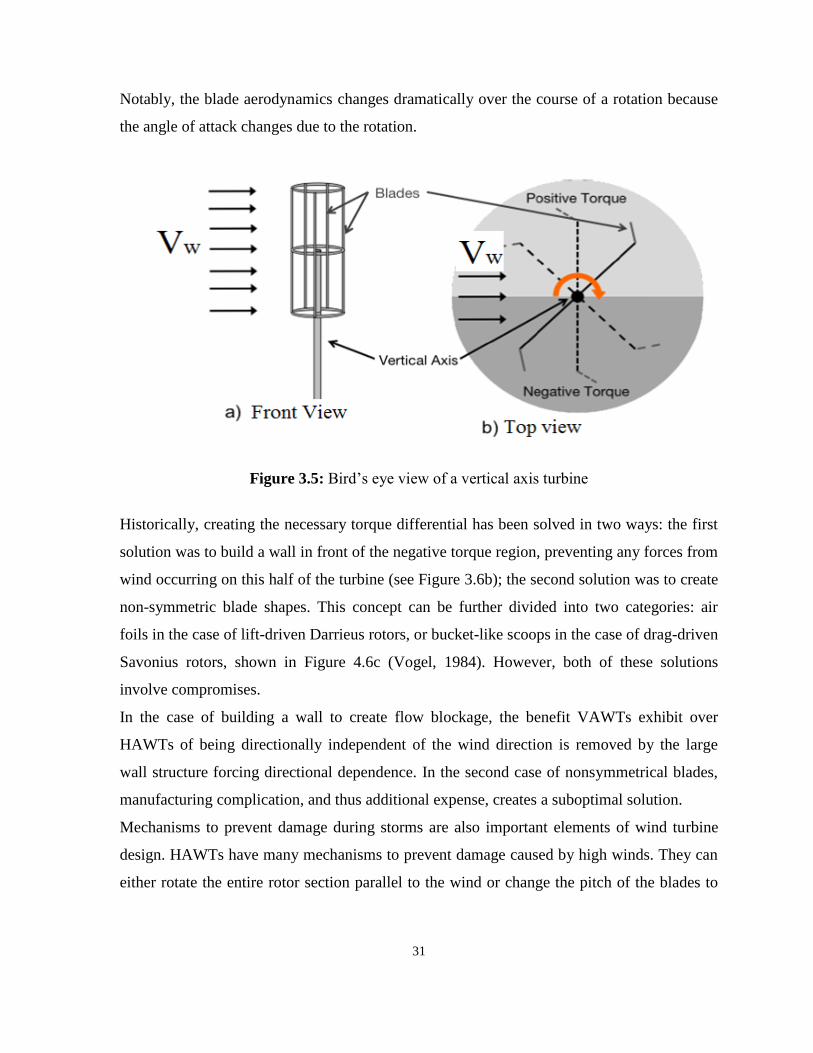
Notably, the blade aerodynamics changes dramatically over the course of a rotation because
the angle of attack changes due to the rotation.
Figure 3.5: Bird’s eye view of a vertical axis turbine
Historically, creating the necessary torque differential has been solved in two ways: the first
solution was to build a wall in front of the negative torque region, preventing any forces from
wind occurring on this half of the turbine (see Figure 3.6b); the second solution was to create
non-symmetric blade shapes. This concept can be further divided into two categories: air
foils in the case of lift-driven Darrieus rotors, or bucket-like scoops in the case of drag-driven
Savonius rotors, shown in Figure 4.6c (Vogel, 1984). However, both of these solutions
involve compromises.
In the case of building a wall to create flow blockage, the benefit VAWTs exhibit over
HAWTs of being directionally independent of the wind direction is removed by the large
wall structure forcing directional dependence. In the second case of nonsymmetrical blades,
manufacturing complication, and thus additional expense, creates a suboptimal solution.
Mechanisms to prevent damage during storms are also important elements of wind turbine
design. HAWTs have many mechanisms to prevent damage caused by high winds. They can
either rotate the entire rotor section parallel to the wind or change the pitch of the blades to

32
avoid over-spinning. In contrast, VAWTs have relied on both mechanical and electrical
breaks to prevent the turbine rotor from spinning too fast.
Figure 3.6: Geometry of vertical axis wind turbine designs as viewed from above the
Turbines
From Figure 3.6;
a. Shows a VAWT with perfect symmetry, which is therefore unable to rotate,
b. Shows the use of a wall in front of half the turbine to impose the force
differential needed for rotation,
c. Shows a Savonius turbine, which uses geometric differences to break the
symmetry of forces acting on the blades.
This body of work explores the simple solution of using at, rectangular sheets of pliable
materials as the blades of a VAWT. The idea sprang from the drag enhancement as well as
drag reduction qualities of shape reconfiguration. Vogel, 1984. and Crosselin, 2010, noted
that pliable structures have both drag enhancing and drag reducing properties, dependent
only on the angle of attack of the blade relative to its clamp and fluid flow direction. The
principle was incorporated in a turbine design, which used reconfiguration to produce a
torque differential across the turbine. The positive torque side would use drag enhancement,
while the negative torque side would minimize forces acting on the turbine by utilizing the
drag reduction.
The studied wind energy converter is a VAWT, which is a less common type of wind turbine.
The VAWT is Omni-directional, i.e. it accepts wind from all directions and does not need a
yawing mechanism. In addition, the vertical axis wind turbine is predictable to produce less
noise than a horizontal axis wind turbine (Ribrant & Bertling, 2007).
The studied system has a turbine with straight blades, which are attached to the drive shaft
via support arms. This configuration is commonly called an H-rotor as in (Eriksson et al.,

33
2008). The simplicity is the main advantage with this wind turbine concept. The wind turbine
consists of few parts and will only have one rotating part. The omission of the gearbox,
yawing system and pitch system is expected to reduce maintenance (Roynarin & Leung,
2002). The blades will be fixed, i.e. it will not be possible to turn them out of the wind. The
absorbed power will be controlled by an electrical control system combined with passive stall
control, i.e. the blades will be designed to stall to limit power absorption at high wind speeds.
The generator of the vertical rotational axis of wind turbine is located at the bottom of the
tower. This is expected to simplify installation and maintenance. The tower can be lighter for
a VAWT since the nacelle is excluded, which reduces structural loads and problems with
erecting the tower (Angelin et al., 1981). The generator design is focused on efficiency, cost
and minimizing maintenance, as the size of the generator is not the main concern. In
advantage, the control system can also be located at ground level facilitating access (Earnest,
2014). There is an apparent difference in the drive train between a HAWT and a VAWT with
a ground based generator (apart from turbine configuration): the length of the drive shaft.
The long drive shaft of this type of VAWT is interesting to field of study. Although, the long
drive shaft is not unique for this system; it is has been used in hydropower. In
Järnvägsforsen, Sweden, a hydropower station with two turbine-generator systems of the
long shaft type was is installed, each having a rated power of 60 MVA, a drive shaft length of
45 meters and a shaft outer diameter of 1.4 meters (Abzug & Larrabee, 2002).
3.6.1 Working Principle of VAWT
In the VAWT design which may be two-bladed, three-bladed or four-bladed, the blades are
symmetrically arranged around a vertical axis and the angles of the blades are set optimally
in such a manner so that it works on the lift principle.
For a rotating VAWT, the blades encounter two forces its own rotating speed and the
incoming wind speed (see Figure 3.5). There is a tangential force pulling the blade around
and radial force acting against the bearing of vertical axis. Both speeds get added vectorially
yielding a total apparent wind speed at an incoming angle of attack. The incoming air stream
which is parallel to the blade yields high and low pressure regions on the blade, yielding
overall lift and drag forces. The resulting oblique lift force creates a torque on the shaft to
which the blades are attached making them rotate in the direction of the blades in which they

34
are already travelling. The VAWT yield an overall positive torque that can be extracted as
electrical power through the generator.
Figure 3.7: Lift principle of three-bladed VAWT Rotor: The aerofoil of the blades are
adjusted
A major limitation of the VAWT is that it is not self-starting due to symmetry of the blades.
Hence, to generate a torque on its own, stating is achieved by operating the electrical
generator as a motor and then speeding up the VAWT sufficiently for the wind to pass over
the blade aerofoil to create the lift force and then run in the generating mode. Torque is
caused by change in the apparent wind direction relative to the moving blades (Burton,
2001).
35
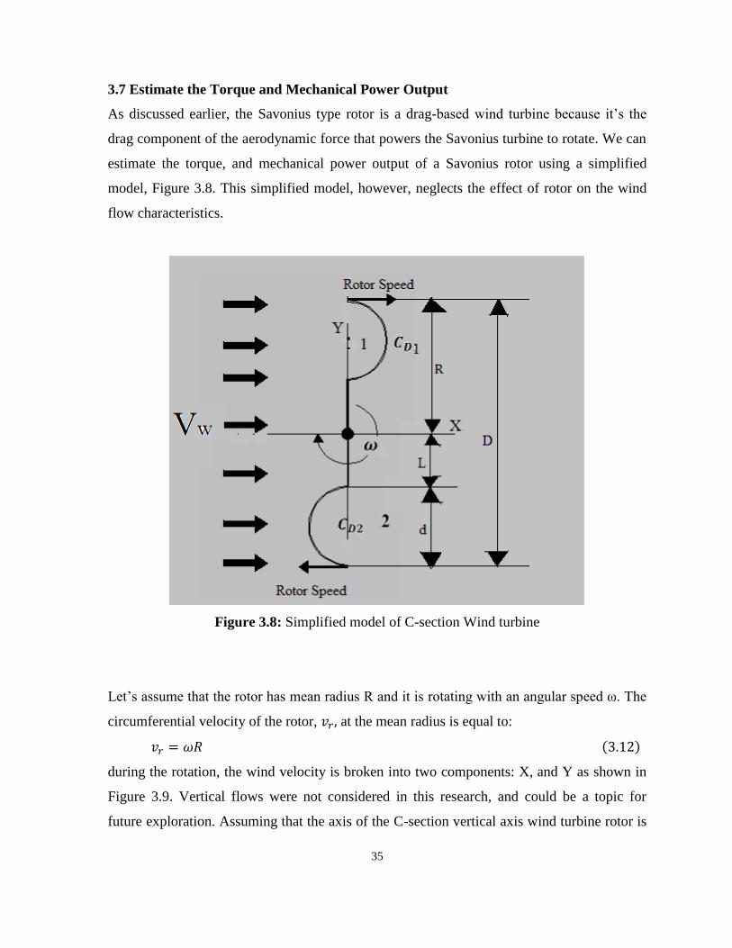
3.7 Estimate the Torque and Mechanical Power Output
As discussed earlier, the Savonius type rotor is a drag-based wind turbine because it’s the
drag component of the aerodynamic force that powers the Savonius turbine to rotate. We can
estimate the torque, and mechanical power output of a Savonius rotor using a simplified
model, Figure 3.8. This simplified model, however, neglects the effect of rotor on the wind
flow characteristics.
Figure 3.8: Simplified model of C-section Wind turbine
Let’s assume that the rotor has mean radius R and it is rotating with an angular speed ω. The
circumferential velocity of the rotor, at the mean radius is equal to:
( )
during the rotation, the wind velocity is broken into two components: X, and Y as shown in
Figure 3.9. Vertical flows were not considered in this research, and could be a topic for
future exploration. Assuming that the axis of the C-section vertical axis wind turbine rotor is

36
the upward-pointing Y-axis, the flow experienced in the X-direction is the sum of the free-
stream flow in the X-direction, and the X-aspect of rotational velocity (see Figure 3.10).
Let assume that the rotor is not rotating (see Figure 3.8), then the average relative velocities
of the wind and at the first and second rotating drums are given by following
expressions, respectively (see Figure 3.9).
( )
( )
The resulting drag forces and on the rotating drums are given as:
( )
(
)
( )
( )
(
)
( )
where, A denotes projected area of the drums. The aerodynamic torque along the central axis
is calculated as:
( ) (
)
[ (
)
(
)
] (
) ( )
The mechanical power by the turbine can be then determined using the following equation
[ (
)
(
)
] (
)
( )
The expression [ (
)
(
)
] is defined as power coefficient, ,. It can
be noted from equation (3.15) that the mechanical power produced by a C-section turbine is
directly proportion to the total projected area by the rotor and the cube of upstream wind
speed (Priya et al., 2013).

37
Figure 3.9: Vector components of the wind speed of C-section rotor
Figure 3.10: Scheme of a C-section rotor showing the velocity of the rotor and wind speed

38
3.8 Rotational Speed
The aim of the wind turbine designer is the production of energy at minimum cost, subject to
constraints imposed by environmental impact considerations. However, blade designs
optimized for a number of different rotational speeds but the same rated power produce
substantially the same energy yield, so the choice of rotational speed is based on machine
cost rather than energy yield. One of the key cost drivers is the rotor torque at rated power, as
this is the main determinant of the drive train cost. For a given tip radius and machine rating,
the rotor torque is inversely proportional to rotational speed, which argues for the adoption of
a high rotational speed. However increasing the rotational speed has adverse effects on the
rotor design, which are explored in the following sections (Burton, 2001).

39
CHAPTER 4
METHODOLOGY
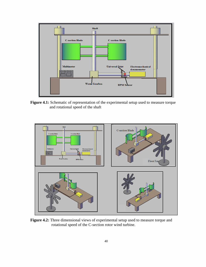
4.1 Vertical Axis C-Section Wind Turbine
The experiment used a model of C-section vertical axis wind turbine with two, three and four
blades. Figure 4.1 and 4.2 show the experimental setup with two blades C-section vertical
axis wind turbine as an example. The shaft and blades of the C-section rotor is made of
stainless steel and PVC material, respectively. Different number of blades and smooth
surface design is intended to increase the capability of wind energy capture. The C-section
vertical axis wind turbine is connected to the electromechanical dynamometer through a
worm gearbox to produce mechanical power, and then convert it into electricity for domestic
powered generation. The turbine captures wind and moves due to the presence of drag forces,
which cause it to rotate around its fixed axis as shown in Figure 4.1 and 4.2. The dimensions
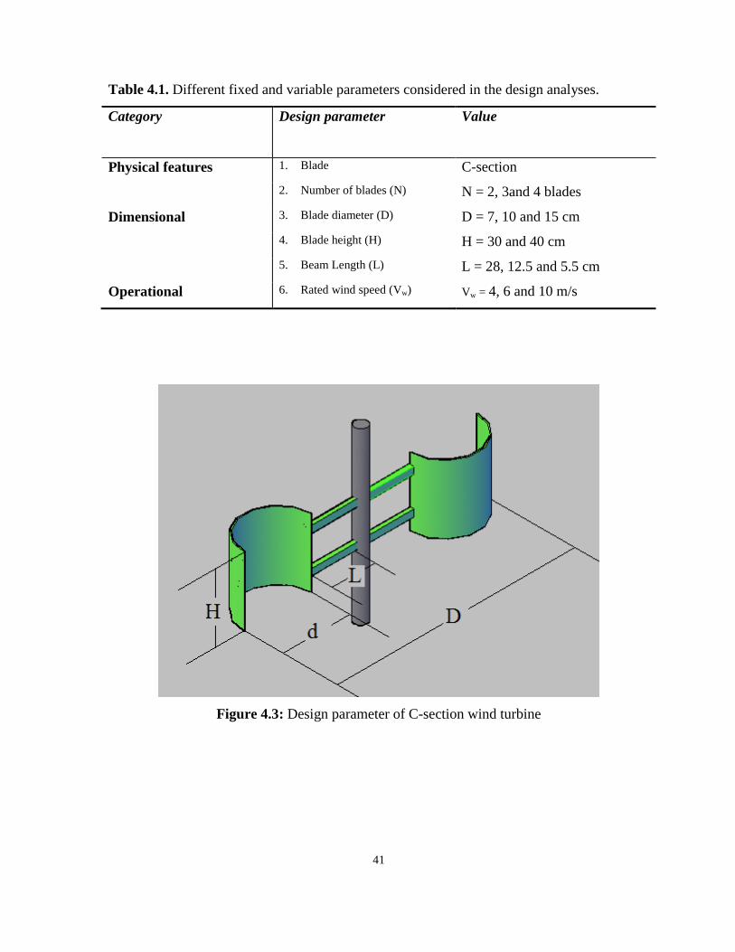
of C-section vertical axis wind turbine model are the diameter of the blade, D, (D = 7, 10 and
15cm), blade height, H, (H =30 and 40 cm), rotor radius, R, (R = 28, 12.5 and 5.5 cm) is
shown in Table 4.1 and Figure 4.3. Additionally, a floor fan is used as the wind source for
doing experiments with C-section wind turbine as shown in Figure 4.2. The wind velocity,
Vw, was set at 4, 8 and 10 m/s by adjusting the distance between the floor fan and C-section
wind turbine and the wind speed switch settings on the fan to see the performance of the
turbine under this controlled environment.
40
Figure 4.1: Schematic of representation of the experimental setup used to measure torque
and rotational speed of the shaft
Figure 4.2: Three dimensional views of experimental setup used to measure torque and
rotational speed of the C-section rotor wind turbine.
41
Table 4.1. Different fixed and variable parameters considered in the design analyses.
Category Design parameter Value
Physical features 1. Blade C-section
2. Number of blades (N) N = 2, 3and 4 blades
Dimensional 3. Blade diameter (D) D = 7, 10 and 15 cm
4. Blade height (H) H = 30 and 40 cm
5. Beam Length (L) L = 28, 12.5 and 5.5 cm
Operational 6. Rated wind speed (Vw) Vw = 4, 6 and 10 m/s
Figure 4.3: Design parameter of C-section wind turbine
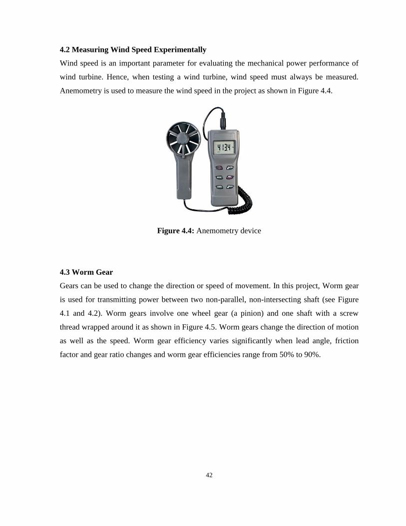
42
4.2 Measuring Wind Speed Experimentally
Wind speed is an important parameter for evaluating the mechanical power performance of
wind turbine. Hence, when testing a wind turbine, wind speed must always be measured.
Anemometry is used to measure the wind speed in the project as shown in Figure 4.4.
Figure 4.4: Anemometry device
4.3 Worm Gear
Gears can be used to change the direction or speed of movement. In this project, Worm gear
is used for transmitting power between two non-parallel, non-intersecting shaft (see Figure
4.1 and 4.2). Worm gears involve one wheel gear (a pinion) and one shaft with a screw
thread wrapped around it as shown in Figure 4.5. Worm gears change the direction of motion
as well as the speed. Worm gear efficiency varies significantly when lead angle, friction
factor and gear ratio changes and worm gear efficiencies range from 50% to 90%.
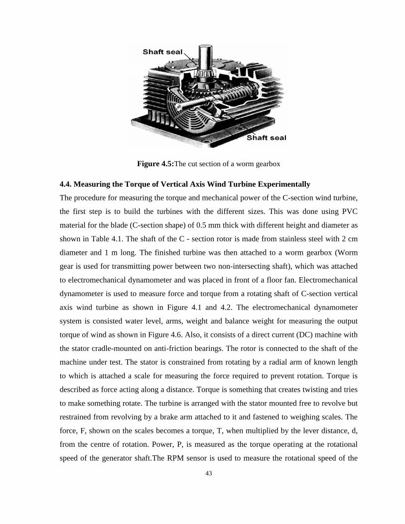
43
Figure 4.5:The cut section of a worm gearbox
4.4. Measuring the Torque of Vertical Axis Wind Turbine Experimentally
The procedure for measuring the torque and mechanical power of the C-section wind turbine,
the first step is to build the turbines with the different sizes. This was done using PVC
material for the blade (C-section shape) of 0.5 mm thick with different height and diameter as
shown in Table 4.1. The shaft of the C - section rotor is made from stainless steel with 2 cm
diameter and 1 m long. The finished turbine was then attached to a worm gearbox (Worm
gear is used for transmitting power between two non-intersecting shaft), which was attached
to electromechanical dynamometer and was placed in front of a floor fan. Electromechanical
dynamometer is used to measure force and torque from a rotating shaft of C-section vertical
axis wind turbine as shown in Figure 4.1 and 4.2. The electromechanical dynamometer
system is consisted water level, arms, weight and balance weight for measuring the output
torque of wind as shown in Figure 4.6. Also, it consists of a direct current (DC) machine with
the stator cradle-mounted on anti-friction bearings. The rotor is connected to the shaft of the
machine under test. The stator is constrained from rotating by a radial arm of known length
to which is attached a scale for measuring the force required to prevent rotation. Torque is
described as force acting along a distance. Torque is something that creates twisting and tries
to make something rotate. The turbine is arranged with the stator mounted free to revolve but
restrained from revolving by a brake arm attached to it and fastened to weighing scales. The
force, F, shown on the scales becomes a torque, T, when multiplied by the lever distance, d,
from the centre of rotation. Power, P, is measured as the torque operating at the rotational
speed of the generator shaft.The RPM sensor is used to measure the rotational speed of the

44
shaft which was placed under the special universal joint as shown in Figure 4.1 and 4.2. This
RPM sensor is connected to multimeter device reader. However, the multimeter device
reader is device used to read the RPM of the shaft as shown in Figure 4.2. The floor fan was
turned into low power and adjusting the distance between the floor fan and C-section wind
turbine, where it would be emitting a wind speed of 4 m/s. The RPM reading on the
multimeter and wind speed result on the anemometry were recorded, as well as the distance
and weight for calculating the torque of the C-section turbine. Then, floor fan is turned to
medium and high power, and recorded the same data. The same method is used to make and
test the other turbines, and recorded the same data.
The formula for torque and power are:
( )
( )
Figure 4.6: Scheme of electromechanical dynamometer (Front and right views) showing the
components of electromechanical dynamometer
4.4Theoretical Procedures for Calculating the Mechanical Power
As mentioned in the previous chapter, the procedures of power calculation of C-section
vertical axis wind turbine can be described as the following steps and shown in Figure 4.7:
1. Analysis the velocity component into X-axis and Y-axis which depends on the position of
the blade as shown in Figure 3.9.
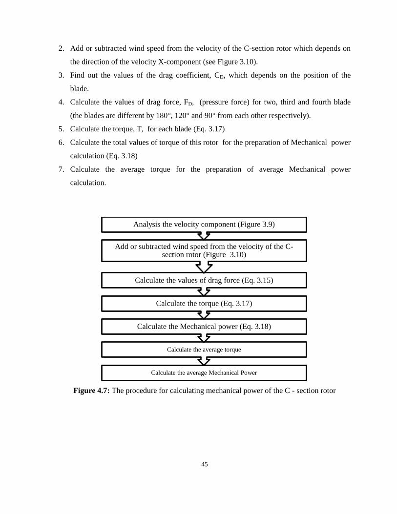
45
2. Add or subtracted wind speed from the velocity of the C-section rotor which depends on
the direction of the velocity X-component (see Figure 3.10).
3. Find out the values of the drag coefficient, CD, which depends on the position of the
blade.
4. Calculate the values of drag force, FD, (pressure force) for two, third and fourth blade
(the blades are different by 180°, 120° and 90° from each other respectively).
5. Calculate the torque, T, for each blade (Eq. 3.17)
6. Calculate the total values of torque of this rotor for the preparation of Mechanical power
calculation (Eq. 3.18)
7. Calculate the average torque for the preparation of average Mechanical power
calculation.
Figure 4.7: The procedure for calculating mechanical power of the C - section rotor
Calculate the average Mechanical Power
Calculate the average torque
Calculate the Mechanical power (Eq. 3.18)
Calculate the torque (Eq. 3.17)
Calculate the values of drag force (Eq. 3.15)
Add or subtracted wind speed from the velocity of the C-section rotor (Figure 3.10)
Analysis the velocity component (Figure 3.9)
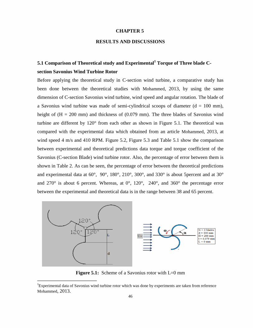
46
CHAPTER 5
RESULTS AND DISCUSSIONS
5.1 Comparison of Theoretical study and Experimental1 Torque of Three blade C-
section Savonius Wind Turbine Rotor
Before applying the theoretical study in C-section wind turbine, a comparative study has
been done between the theoretical studies with Mohammed, 2013, by using the same
dimension of C-section Savonius wind turbine, wind speed and angular rotation. The blade of
a Savonius wind turbine was made of semi-cylindrical scoops of diameter (d = 100 mm),
height of (H = 200 mm) and thickness of (0.079 mm). The three blades of Savonius wind
turbine are different by 120° from each other as shown in Figure 5.1. The theoretical was
compared with the experimental data which obtained from an article Mohammed, 2013, at
wind speed 4 m/s and 410 RPM. Figure 5.2, Figure 5.3 and Table 5.1 show the comparison
between experimental and theoretical predictions data torque and torque coefficient of the
Savonius (C-section Blade) wind turbine rotor. Also, the percentage of error between them is
shown in Table 2. As can be seen, the percentage of error between the theoretical predictions
and experimental data at 60°, 90°, 180°, 210°, 300°, and 330° is about 5percent and at 30°
and 270° is about 6 percent. Whereas, at 0°, 120°, 240°, and 360° the percentage error
between the experimental and theoretical data is in the range between 38 and 65 percent.
Figure 5.1: Scheme of a Savonius rotor with L=0 mm
1Experimental data of Savonius wind turbine rotor which was done by experiments are taken from reference
Mohammed, 2013.

47
Table 5.1: Theoretical and experimental values of torque and torque coefficient of Savonius
(C-section blade) wind turbine.
Rotor
Angle
[°]
Torque [N.m] Rotor
Angle
[°]
Torque Coefficient
Th. Exp. Absolute
Error [%] Th. Exp.
Absolute
Error [%]
0 0.004184 0.0058 38.36 0 0.13 0.18 38.36
30 0.016132 0.0151 6.31 30 0.5 0.47 6.31
60 0.019084 0.0183 3.96 60 0.59 0.57 3.96
90 0.006734 0.0071 5.05 90 0.21 0.22 5.05
120 0.004276 0.0061 42.90 120 0.13 0.19 42.90
150 0.016132 0.0151 6.31 150 0.5 0.47 6.31
180 0.019084 0.0183 3.96 180 0.59 0.57 3.96
210 0.006734 0.0071 5.05 210 0.21 0.22 5.05
240 0.004276 0.0061 42.90 240 0.13 0.19 42.90
270 0.016132 0.0151 6.31 270 0.5 0.47 6.31
300 0.019084 0.0183 3.96 300 0.59 0.57 3.96
330 0.006734 0.0071 5.05 330 0.21 0.22 5.05
360 0.004276 0.0071 65.46 360 0.13 0.22 65.46
Th.: Theoretical Exp.: Experimental
Figure 5.2: Theoretical predictions and experimental torque of Savonius wind turbine rotor
0
0.005
0.01
0.015
0.02
0.025
0 30 60 90 120 150 180 210 240 270 300 330 360
Torq
ue
[N
.m]
Rotor Angle [°]
Theoretical
Experimental

48
Figure 5.3: Theoretical predictions and experimental torque coefficient of Savonius wind
turbine rotor
5.2. Theoretical Results of Torque of C-section Rotor
As mentioned previously, Torque and mechanical power of the C-section rotor were
calculated for varying numbers and sizes of C-section blades and varying rotor diameter.
Figures 5.4, 5.5 and 5.6 show the torque varies with the change in rotor angle for different
number of blades (2, 3, 4) and blade diameter (7, 10 and 15cm) with fixed blade height (40
cm) and wind speed (4m/s) which were chosen randomly. For two, three, and fourth C-
section blades of vertical axis wind turbine, the blades are different by 180°, 120°, and 90°
from each other respectively. As shown in Figure 5.4, 5.5 and 5.6, the torque increases when
the number and size of blade increased. Furthermore, the periodic motion of the graph of
two, three, and four blades of C-section is very obvious and the motion repeats itself in a
regular fashion. As can see, as the number blades increase than 3 blades, the torque values of
C-section rotor are slightly increased.
Figure 5.6 shows how the torque varies with the change in the rotor angle with a different
blade numbers and wind speed with fixed blade rotor radius and blade diameter where was
chosen randomly. As shown in Figure 5.7, the torque increases when the number of blade
and wind speed are increased. Furthermore, the periodic motion of the graph of two, three
and four blades of C-section is very obvious and the motion repeats itself in a regular pattern.
The increasing in rotor radius leads to increase the torque of C-section blade with fixed blade
0
0.1
0.2
0.3
0.4
0.5
0.6
0.7
0 30 60 90 120 150 180 210 240 270 300 330 360
Torq
ue
Co
eff
icie
nt
Rotor Angle [°]
Theoretical
Experimental
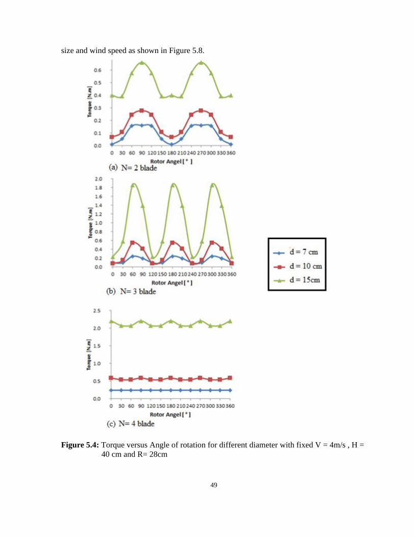
49
size and wind speed as shown in Figure 5.8.
Figure 5.4: Torque versus Angle of rotation for different diameter with fixed V = 4m/s , H =
40 cm and R= 28cm

50
Figure 5.5: Torque versus Angle of rotation for different diameter with fixed V = 6m/s , H =
40 cm and R= 28cm

51
Figure 5.6: Torque versus Angle of rotation for different diameter with fixed V = 10m/s , H
= 40 cm and R= 28cm
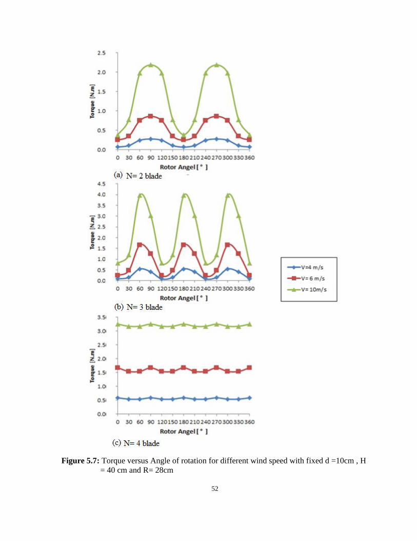
52
Figure 5.7: Torque versus Angle of rotation for different wind speed with fixed d =10cm , H
= 40 cm and R= 28cm
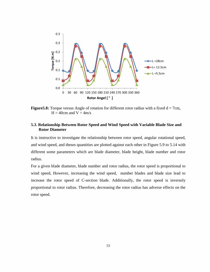
53
Figure5.8: Torque versus Angle of rotation for different rotor radius with a fixed d = 7cm,
H = 40cm and V = 4m/s
5.3. Relationship Between Rotor Speed and Wind Speed with Variable Blade Size and
Rotor Diameter
It is instructive to investigate the relationship between rotor speed, angular rotational speed,
and wind speed, and theses quantities are plotted against each other in Figure 5.9 to 5.14 with
different some parameters which are blade diameter, blade height, blade number and rotor
radius.
For a given blade diameter, blade number and rotor radius, the rotor speed is proportional to
wind speed, However, increasing the wind speed, number blades and blade size lead to
increase the rotor speed of C-section blade. Additionally, the rotor speed is inversely
proportional to rotor radius. Therefore, decreasing the rotor radius has adverse effects on the
rotor speed.
0.0
0.1
0.1
0.2
0.2
0.3
0.3
0 30 60 90 120 150 180 210 240 270 300 330 360
Torq
ue
[N
.m]
Rotor Angel [ ° ]
L =28cm
L= 12.5cm
L =5.5cm
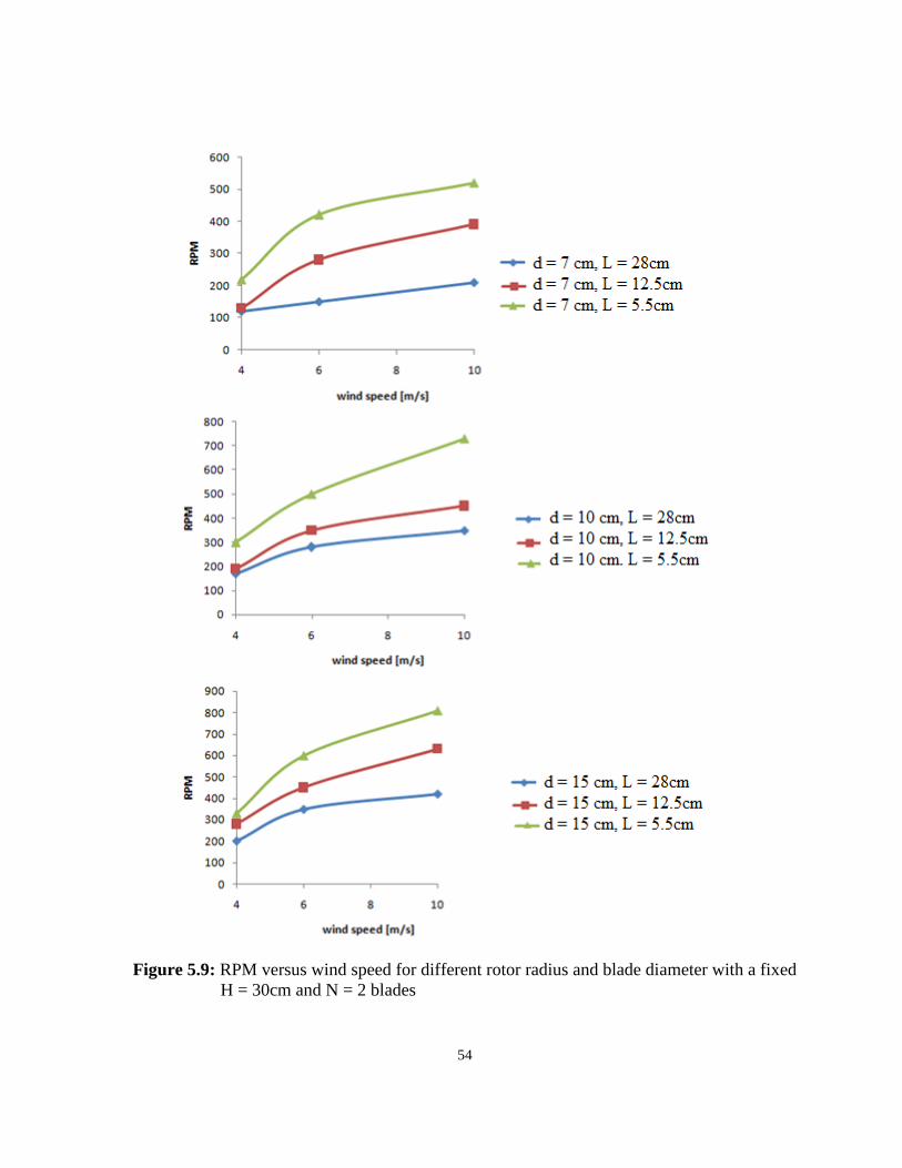
54
Figure 5.9: RPM versus wind speed for different rotor radius and blade diameter with a fixed
H = 30cm and N = 2 blades
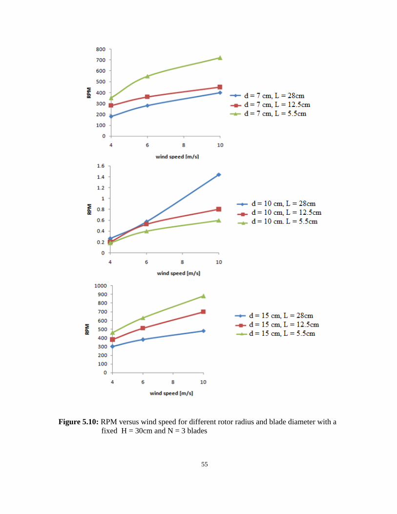
55
Figure 5.10: RPM versus wind speed for different rotor radius and blade diameter with a
fixed H = 30cm and N = 3 blades
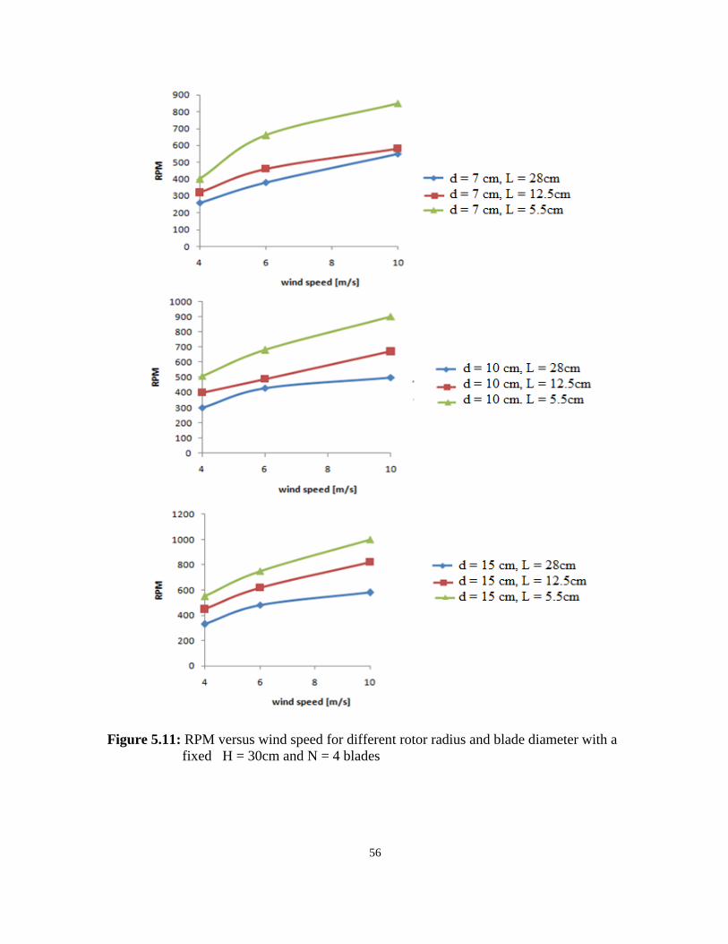
56
Figure 5.11: RPM versus wind speed for different rotor radius and blade diameter with a
fixed H = 30cm and N = 4 blades

57
Figure 5.12: RPM versus wind speed for different rotor radius and blade diameter with a
fixed H = 40cm and N = 2 blades
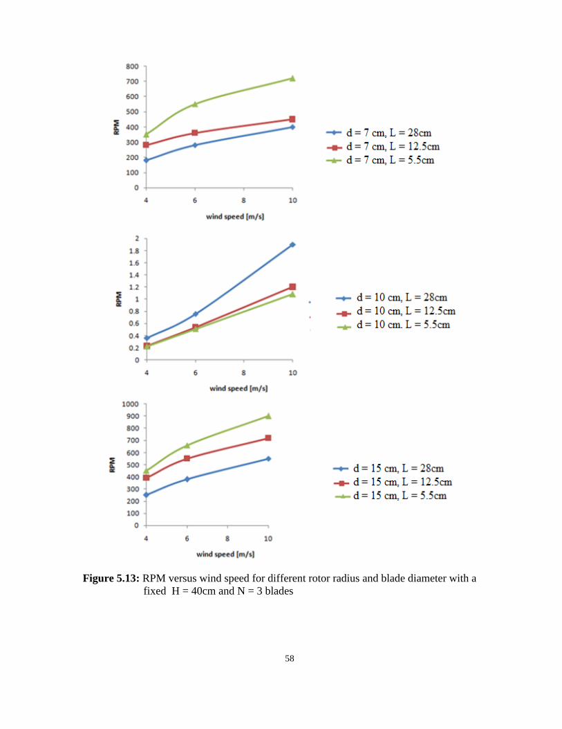
58
Figure 5.13: RPM versus wind speed for different rotor radius and blade diameter with a
fixed H = 40cm and N = 3 blades
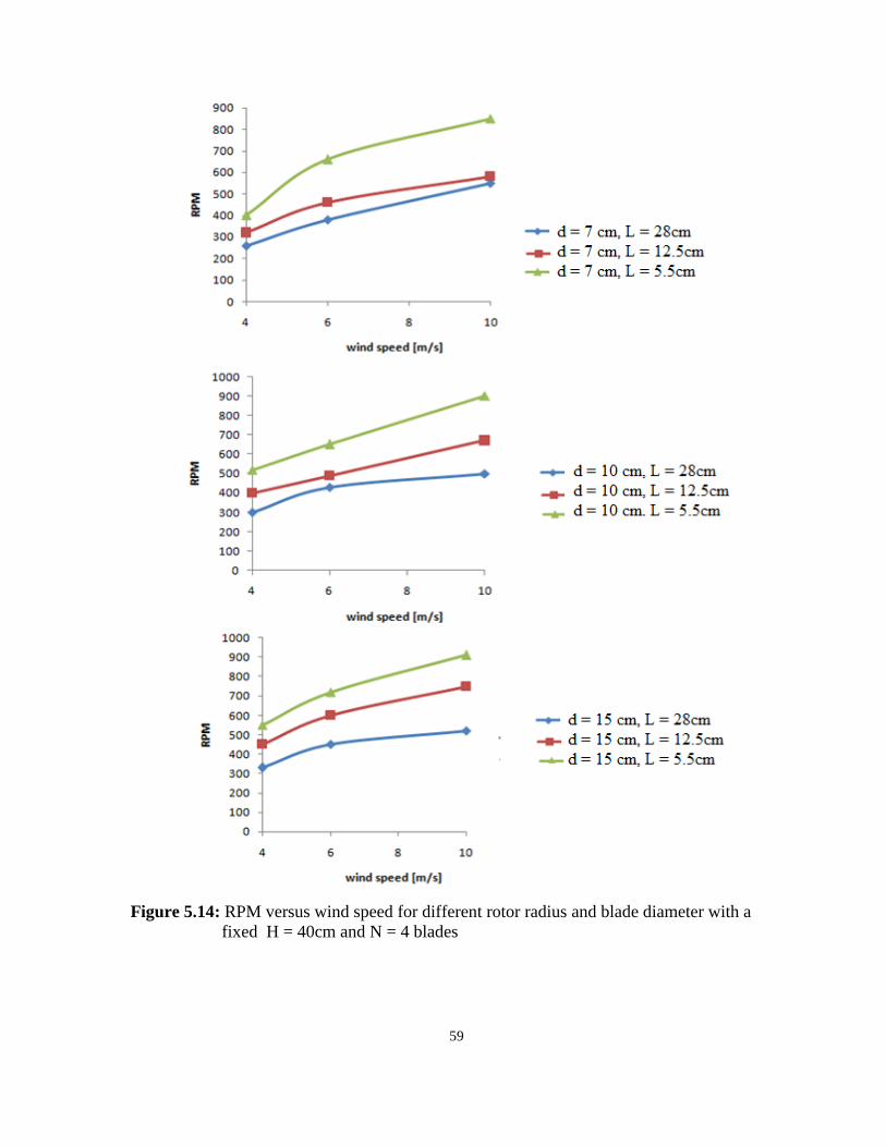
59
Figure 5.14: RPM versus wind speed for different rotor radius and blade diameter with a
fixed H = 40cm and N = 4 blades
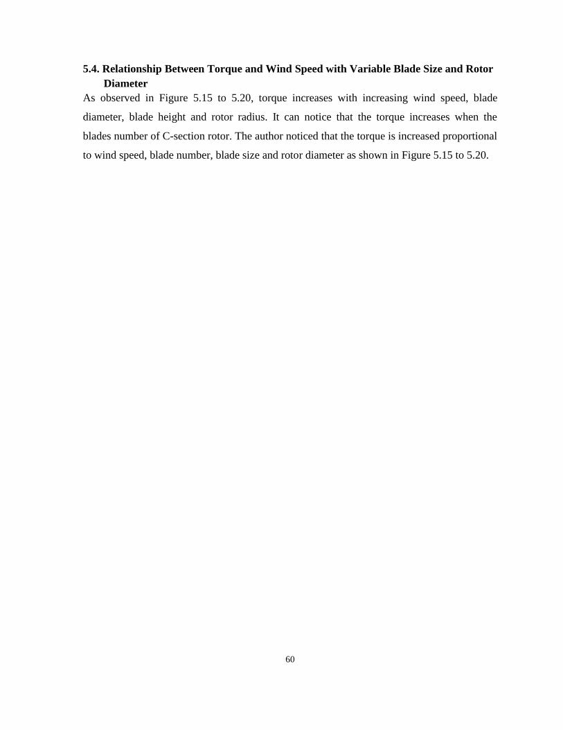
60
5.4. Relationship Between Torque and Wind Speed with Variable Blade Size and Rotor
Diameter
As observed in Figure 5.15 to 5.20, torque increases with increasing wind speed, blade
diameter, blade height and rotor radius. It can notice that the torque increases when the
blades number of C-section rotor. The author noticed that the torque is increased proportional
to wind speed, blade number, blade size and rotor diameter as shown in Figure 5.15 to 5.20.
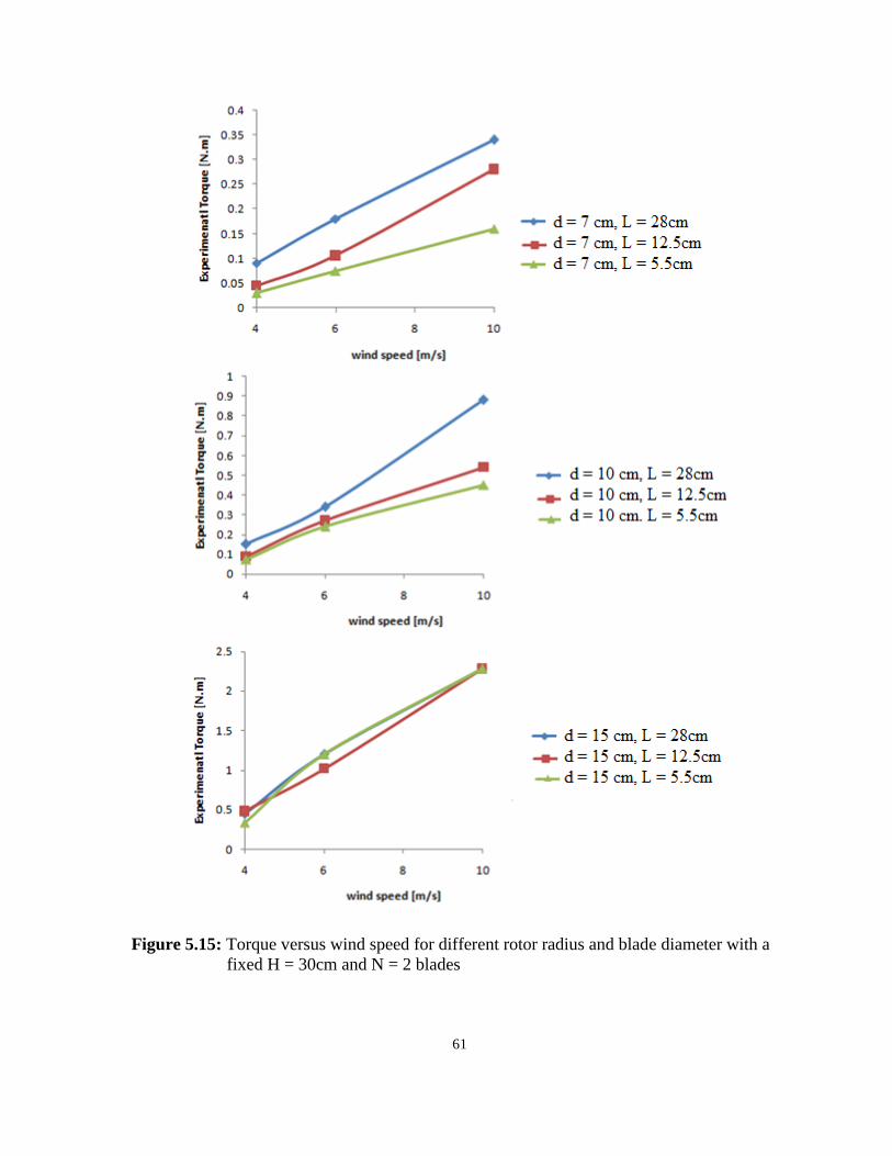
61
Figure 5.15: Torque versus wind speed for different rotor radius and blade diameter with a
fixed H = 30cm and N = 2 blades

62
Figure 5.16: Torque versus wind speed for different rotor radius and blade diameter with a
fixed H = 30cm and N = 3 blades
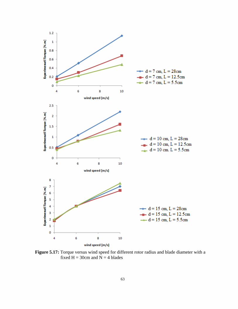
63
Figure 5.17: Torque versus wind speed for different rotor radius and blade diameter with a
fixed H = 30cm and N = 4 blades

64
Figure 5.18: Torque versus wind speed for different rotor radius and blade diameter with a
fixed H = 40cm and N = 2 blades

65
Figure 5.19: Torque versus wind speed for different rotor radius and blade diameter with a
fixed H = 40cm and N = 3 blades
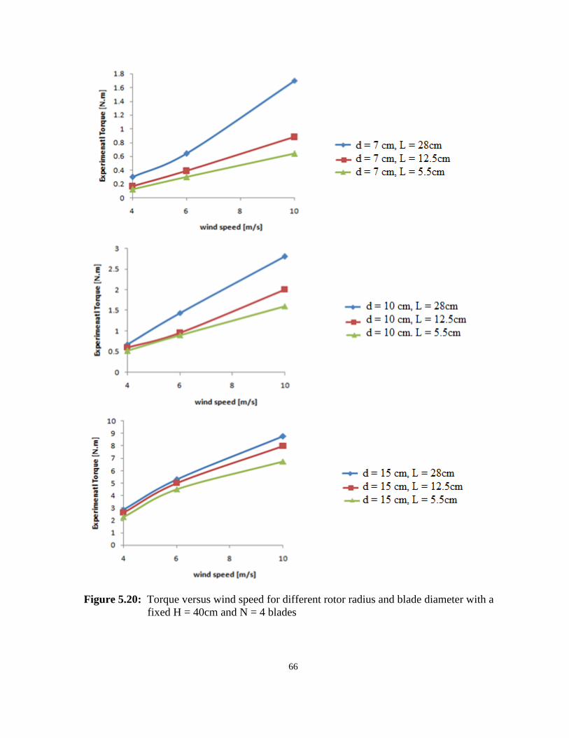
66
Figure 5.20: Torque versus wind speed for different rotor radius and blade diameter with a
fixed H = 40cm and N = 4 blades
67
5.5. Relationship between Torque and Rotor Speed with Variable Blade Size and Rotor
Diameter
Figures 5.21 to 5.26 show the relationship between torque and rotor speed, RPM, at different
blade size and rotor radius. The torque decreases as the rotor speed, RPM, with the C-section
rotor increase. Additionally, they show that the increasing blade number, blade size leads to
increase RPM and Torque. Whereas, RPM increased when the rotor radius of the C-section
rotor decreases. However, the torque is inversely proportional to rotor speed, RPM2 .
However, at constant blade size and blade number, when the torque of C-section rotor
increases, the rotational speed, RPM, decreases as shown in Figures 5.21 to 5.26.
2 The relationship between rotational speed and torque as in references [46]
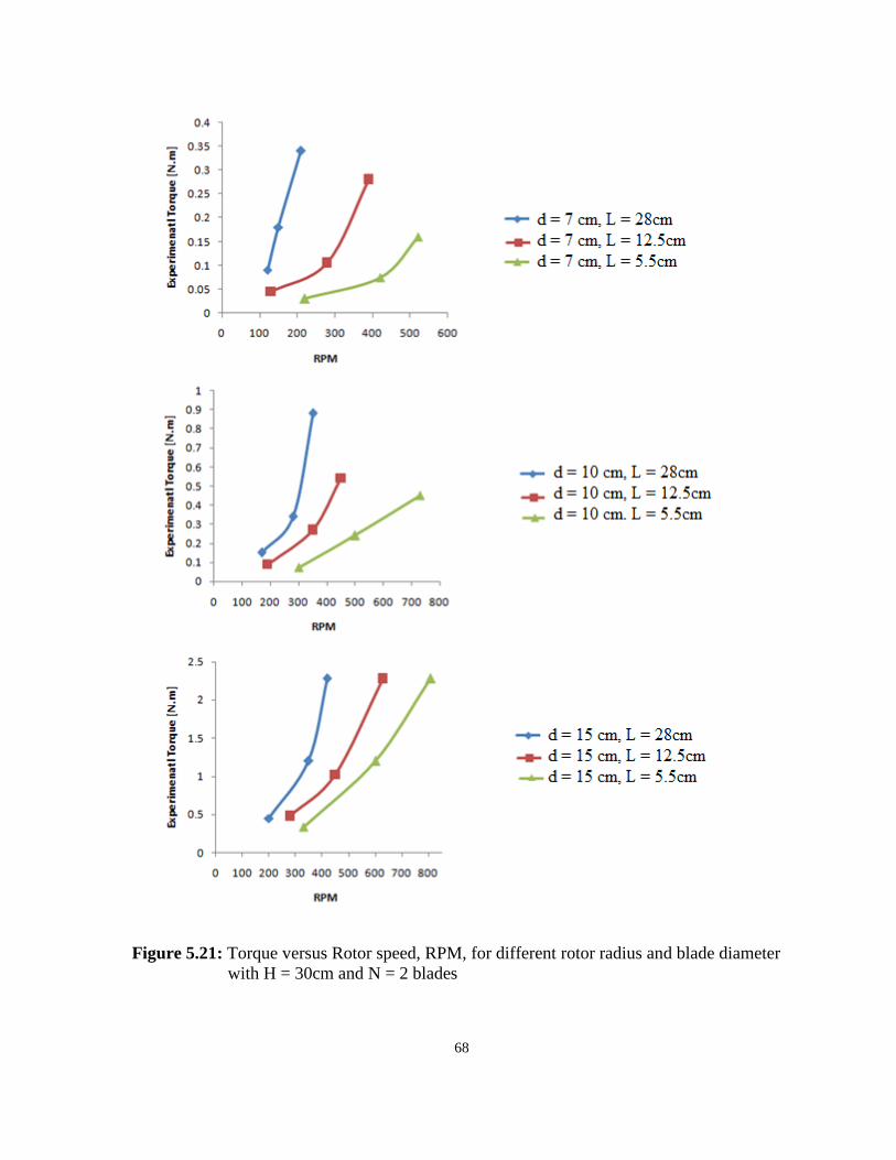
68
Figure 5.21: Torque versus Rotor speed, RPM, for different rotor radius and blade diameter
with H = 30cm and N = 2 blades
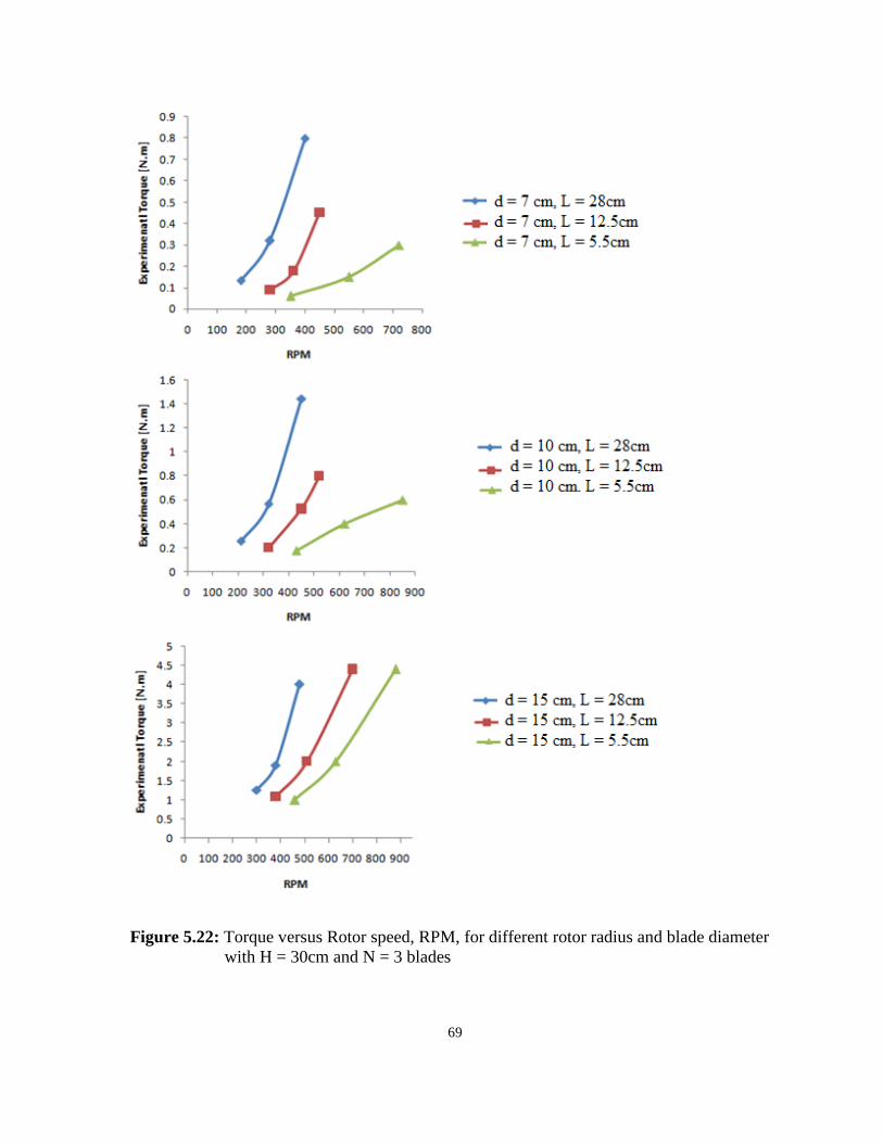
69
Figure 5.22: Torque versus Rotor speed, RPM, for different rotor radius and blade diameter
with H = 30cm and N = 3 blades
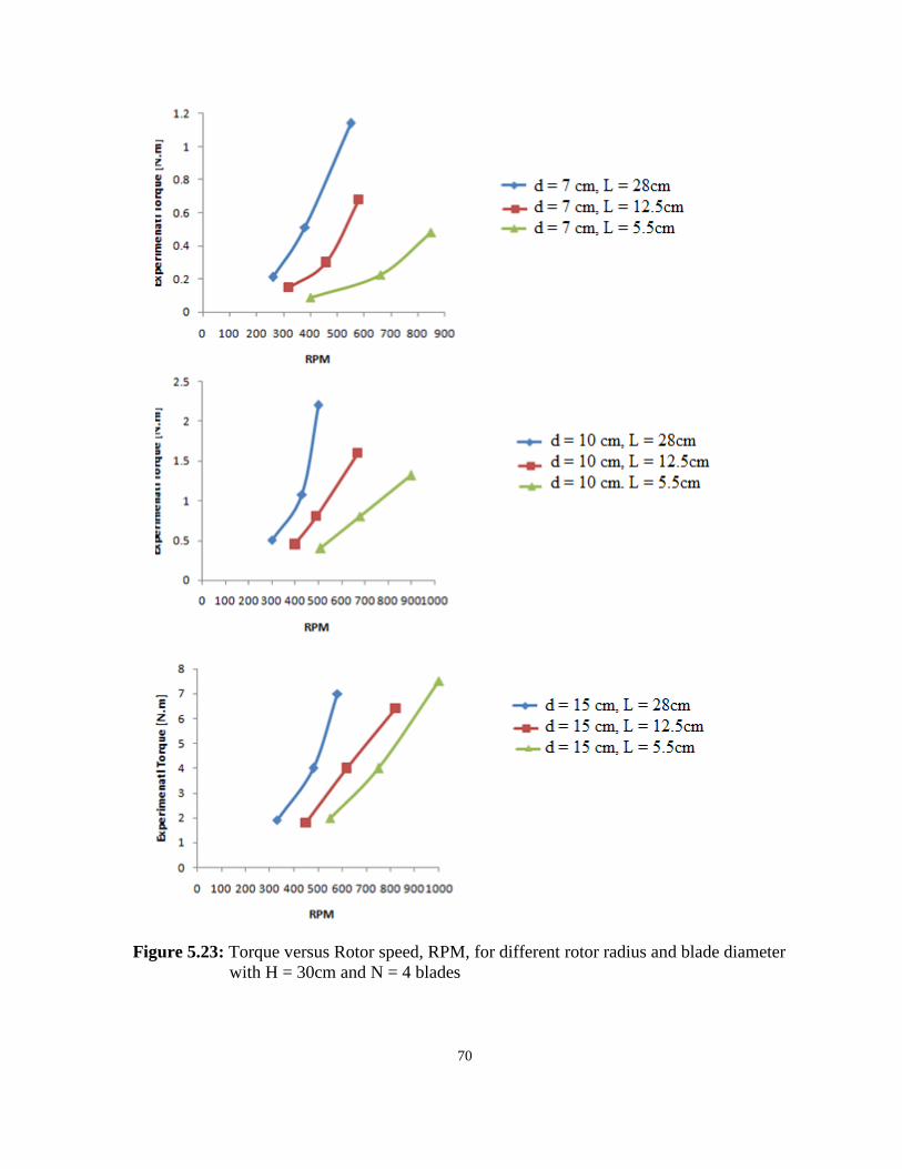
70
Figure 5.23: Torque versus Rotor speed, RPM, for different rotor radius and blade diameter
with H = 30cm and N = 4 blades
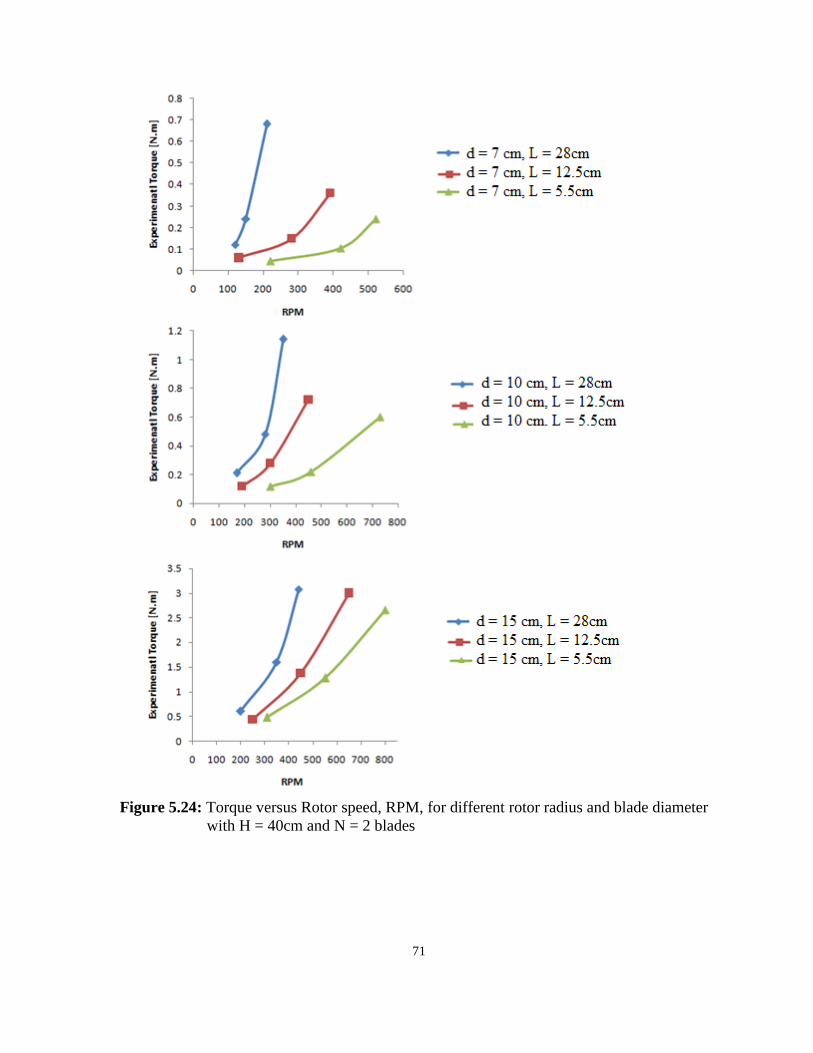
71
Figure 5.24: Torque versus Rotor speed, RPM, for different rotor radius and blade diameter
with H = 40cm and N = 2 blades
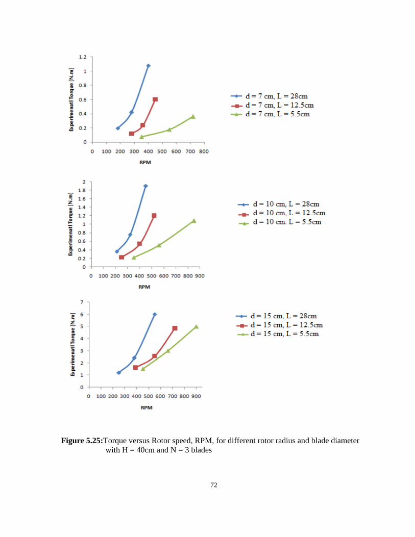
72
Figure 5.25:Torque versus Rotor speed, RPM, for different rotor radius and blade diameter
with H = 40cm and N = 3 blades

73
Figure 5.26: Torque versus Rotor speed, RPM, for different rotor radius and blade diameter
with H = 40cm and N = 4 blades
5.6 Relationship between Torque and Blade Diameter with Variable Blade Height,
Wind Speed and Rotor Diameter

74
Figures 5.27 to 5.31 show the relationship between torque and blade diameter at different
blade height and rotor radius. The torque increases as the blade diameters of C-section rotor
increase. Additionally, they show that the increasing blade number, blade height and wind
speed lead to increase the torque of C-section vertical axis wind turbine. However, the torque
is proportional to blade size, wind speed and number of blade. Also, at constant blade height,
wind speed and blade number, when the blade diameter increases, the torque of C-section
rotor will increase as shown in Figures 5.27 to 5.31.

75
Figure 5.27: Torque versus blade diameter for different rotor radius with fixed H = 30 cm
and N = 2 blades
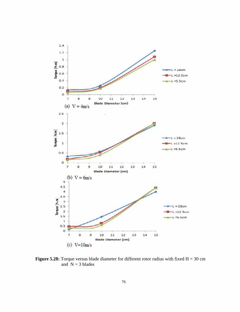
76
Figure 5.28: Torque versus blade diameter for different rotor radius with fixed H = 30 cm
and N = 3 blades

77
Figure 5.29: Torque versus blade diameter for different rotor radius with fixed H = 30 cm
and N = 4 blades
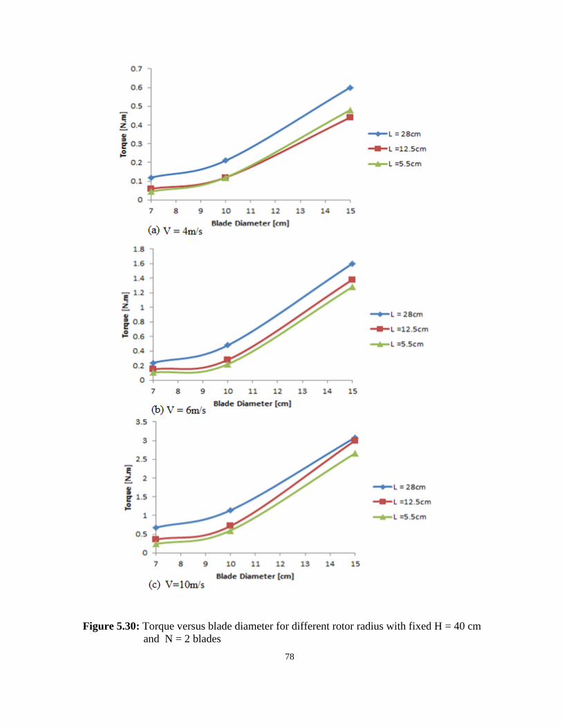
78
Figure 5.30: Torque versus blade diameter for different rotor radius with fixed H = 40 cm
and N = 2 blades
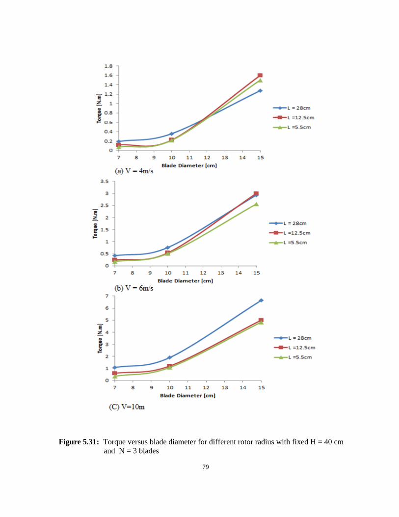
79
Figure 5.31: Torque versus blade diameter for different rotor radius with fixed H = 40 cm
and N = 3 blades

80
Figure 5.32: Torque versus blade diameter for different rotor radius with fixed H = 40 cm
and N = 4 blades;

81
5.7 Comparison of Theoretical Study and Experimental Torque of C-section Wind
Turbine Rotor
Theoretical average torque, traditionally, average torque is calculated by dividing the sum of
all values of theoretical torque at a different rotor angle by a number of the values. It is given
by the formula
∑
( )
Figures 5.33 to 5.38 illustrate the amount of theoretical average torque produced from the
different number of C-section blades with different size at the different wind speed.
Additionally, the comparison between the theoretical predictions and experimental torque are
shown in Figures 5.33 to 5.38. It can notice that the torque, Theoretical and experimental, is
rapidly increasing with the increase in the number of blades, the size of the blades and wind
speed. The absolute error between them is between rang 0 and 15% as shown in Figures.
However, from these Figures, it is clear that as the number of blades, blade size, and wind
speed increase, the torque of C-section rotor wind turbine will increase.
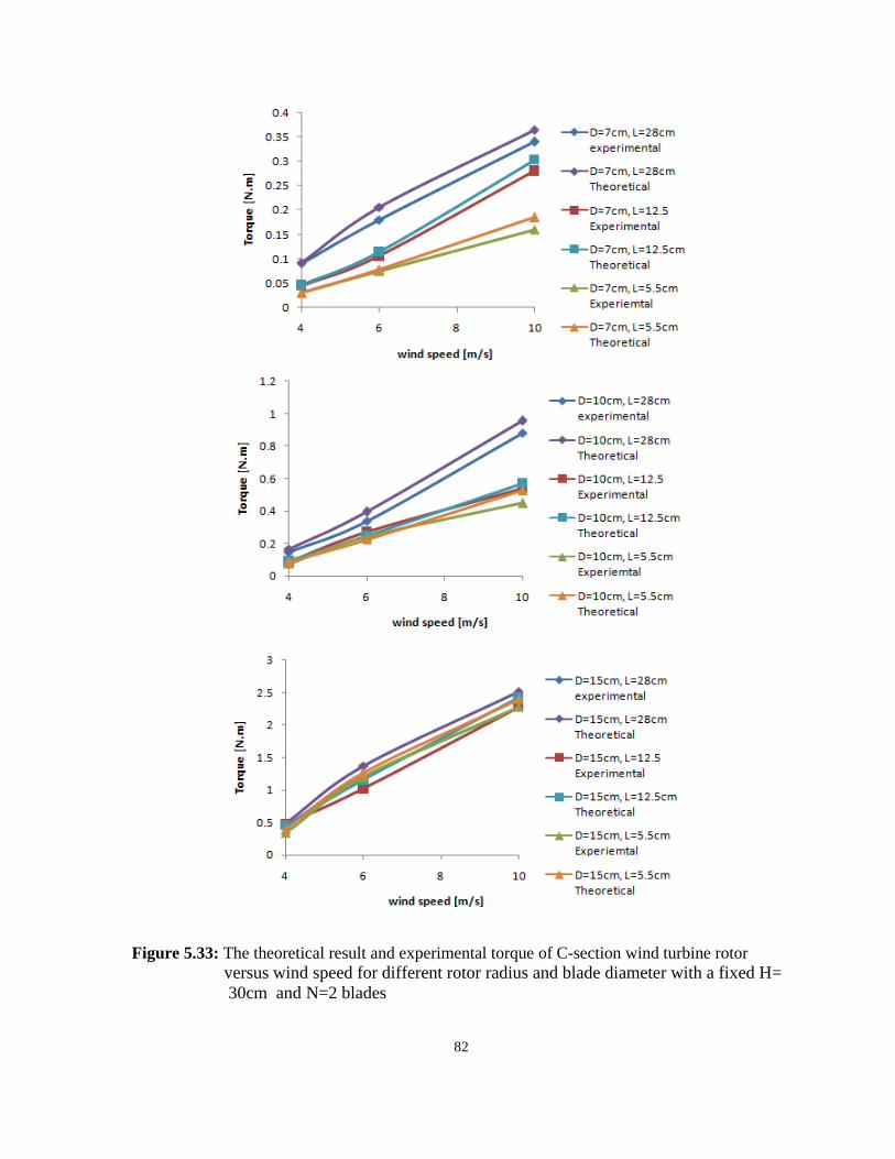
82
Figure 5.33: The theoretical result and experimental torque of C-section wind turbine rotor versus wind speed for different rotor radius and blade diameter with a fixed H=
30cm and N=2 blades
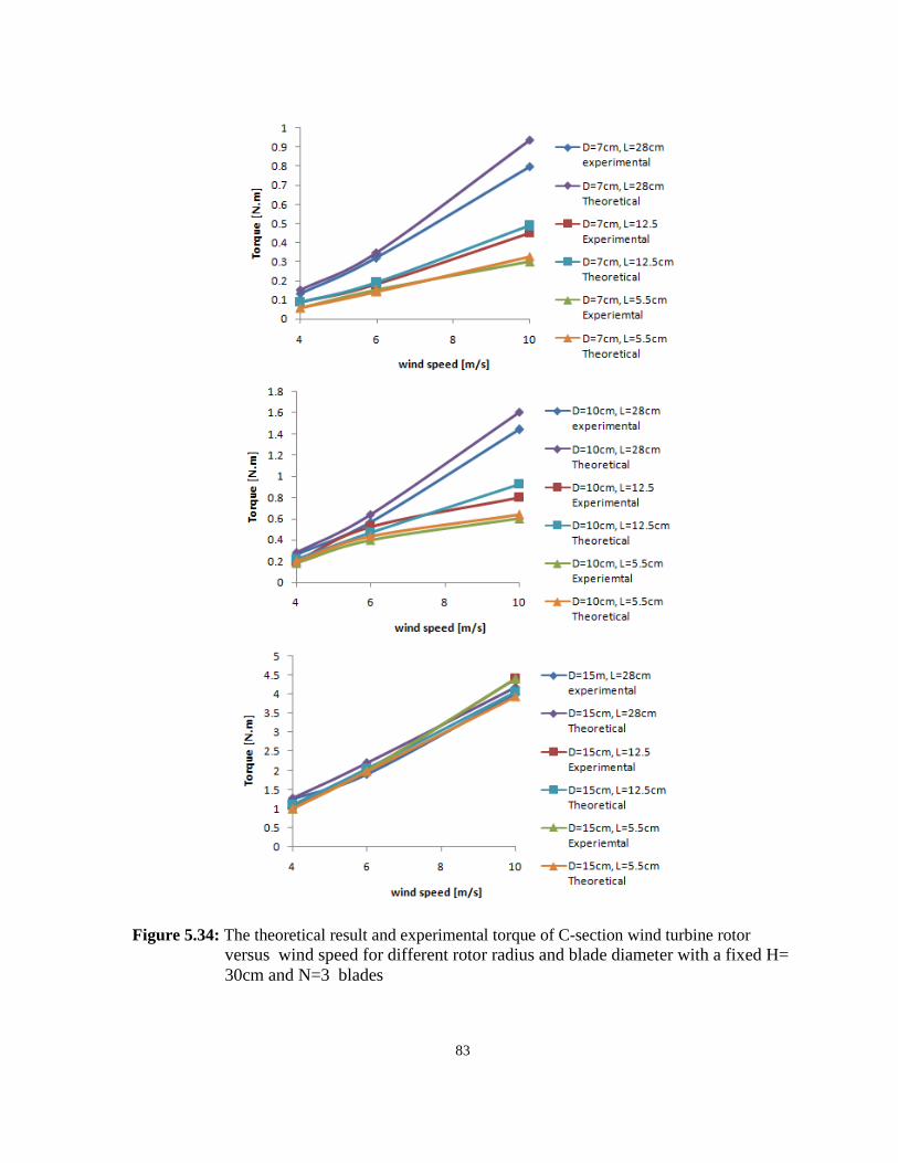
83
Figure 5.34: The theoretical result and experimental torque of C-section wind turbine rotor versus wind speed for different rotor radius and blade diameter with a fixed H=
30cm and N=3 blades
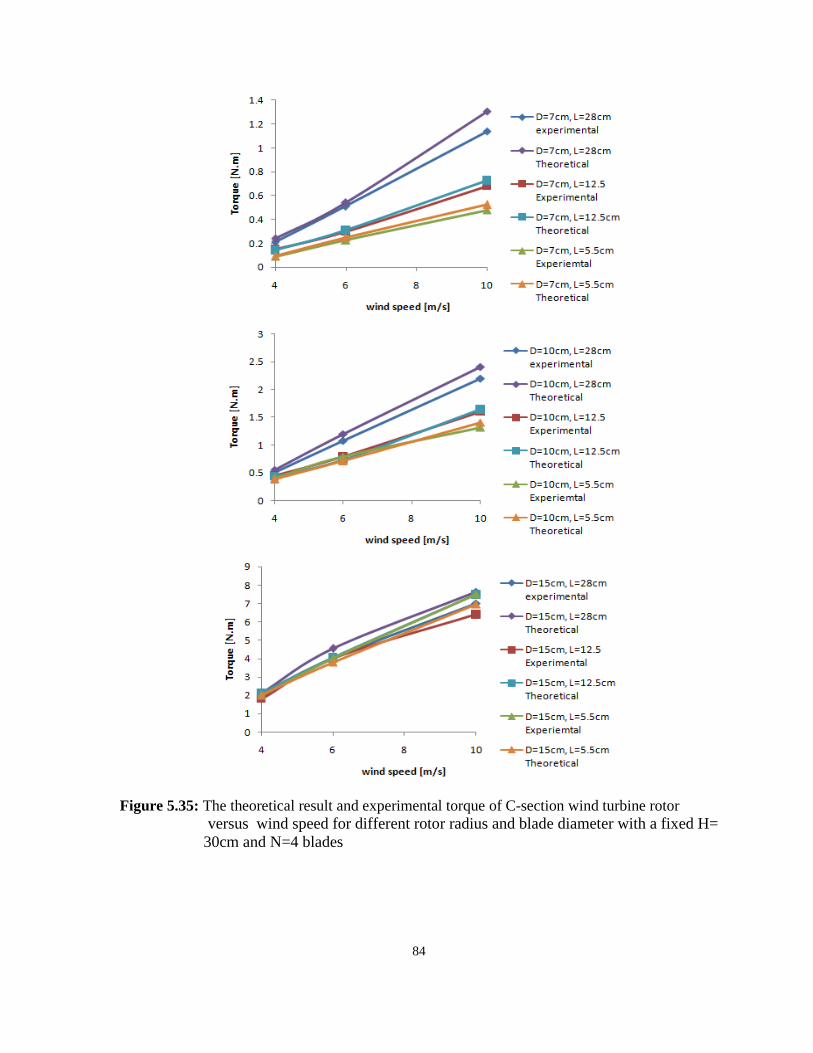
84
Figure 5.35: The theoretical result and experimental torque of C-section wind turbine rotor
versus wind speed for different rotor radius and blade diameter with a fixed H=
30cm and N=4 blades
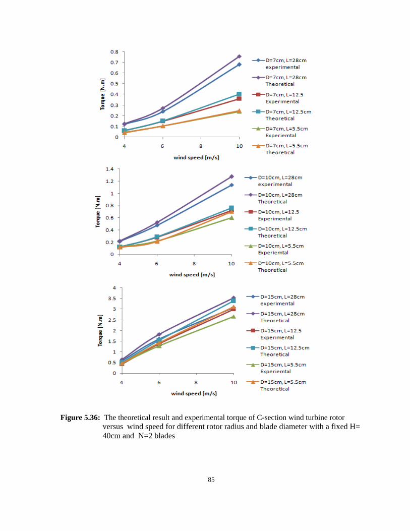
85
Figure 5.36: The theoretical result and experimental torque of C-section wind turbine rotor
versus wind speed for different rotor radius and blade diameter with a fixed H=
40cm and N=2 blades

86
Figure 5.37: The theoretical result and experimental torque of C-section wind turbine rotor versus wind speed for different rotor radius and blade diameter with a fixed H=
40cm and N=3 blades
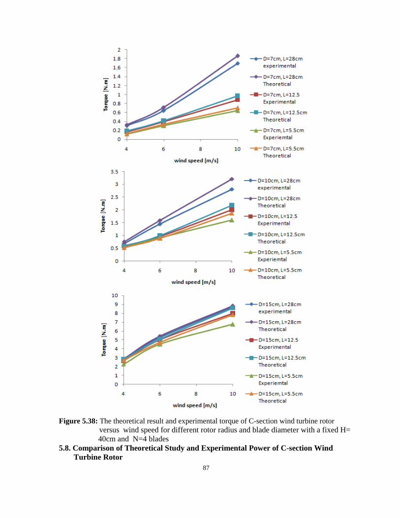
87
Figure 5.38: The theoretical result and experimental torque of C-section wind turbine rotor
versus wind speed for different rotor radius and blade diameter with a fixed H=
40cm and N=4 blades
5.8. Comparison of Theoretical Study and Experimental Power of C-section Wind
Turbine Rotor
88
Theoretical average Mechanical power, traditionally average mechanical power is calculated
by multiplying the average torque by angular speed, rotor speed,. It is given by the formula
( )
Figures 5.39 to 5.44 illustrated the relationship between the average of theoretical mechanical
power and experimental mechanical power and size and number of blades with variable wind
speed. Additionally, it is observed that the absolute error between them is between rang 0 and
15% as shown from these Figures. However, from these figures, it is clear that as the number
of blades, blade size, and wind speed increase, the C-section rotor wind turbine will produce
more mechanical power.
It can notice from the figures that a greater number of blades increase the weight to be turned
by the turbine. On the other hand, more blades provide a greater available surface area for the
wind to push, so it would produce more turning power. Having fewer blades could be
beneficial because it will not be as heavy, and will be easier to turn than a greater number of
blades, but it will also be somewhat inefficient because it produces less turning power.

89
Figure 5.39: The theoretical result and experimental torque of C-section wind turbine rotor
versus wind speed for different rotor radius and blade diameter with a fixed H=
30cm and N= 2 blades

90
Figure 5.40: The theoretical result and experimental torque of C-section wind turbine rotor versus wind speed for different rotor radius and blade diameter with a fixed H=
30cm and N=3 blades

91
Figure 5.41: The theoretical result and experimental torque of C-section wind turbine rotor versus wind speed for different rotor radius and blade diameter with a fixed H=
30cm and N=4 blades
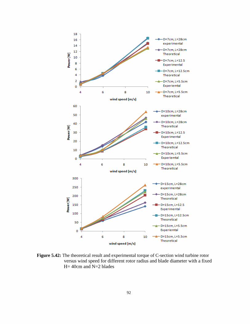
92
Figure 5.42: The theoretical result and experimental torque of C-section wind turbine rotor
versus wind speed for different rotor radius and blade diameter with a fixed
H= 40cm and N=2 blades
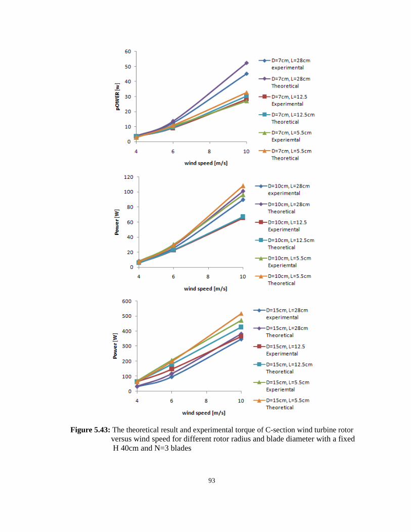
93
Figure 5.43: The theoretical result and experimental torque of C-section wind turbine rotor
versus wind speed for different rotor radius and blade diameter with a fixed
H 40cm and N=3 blades
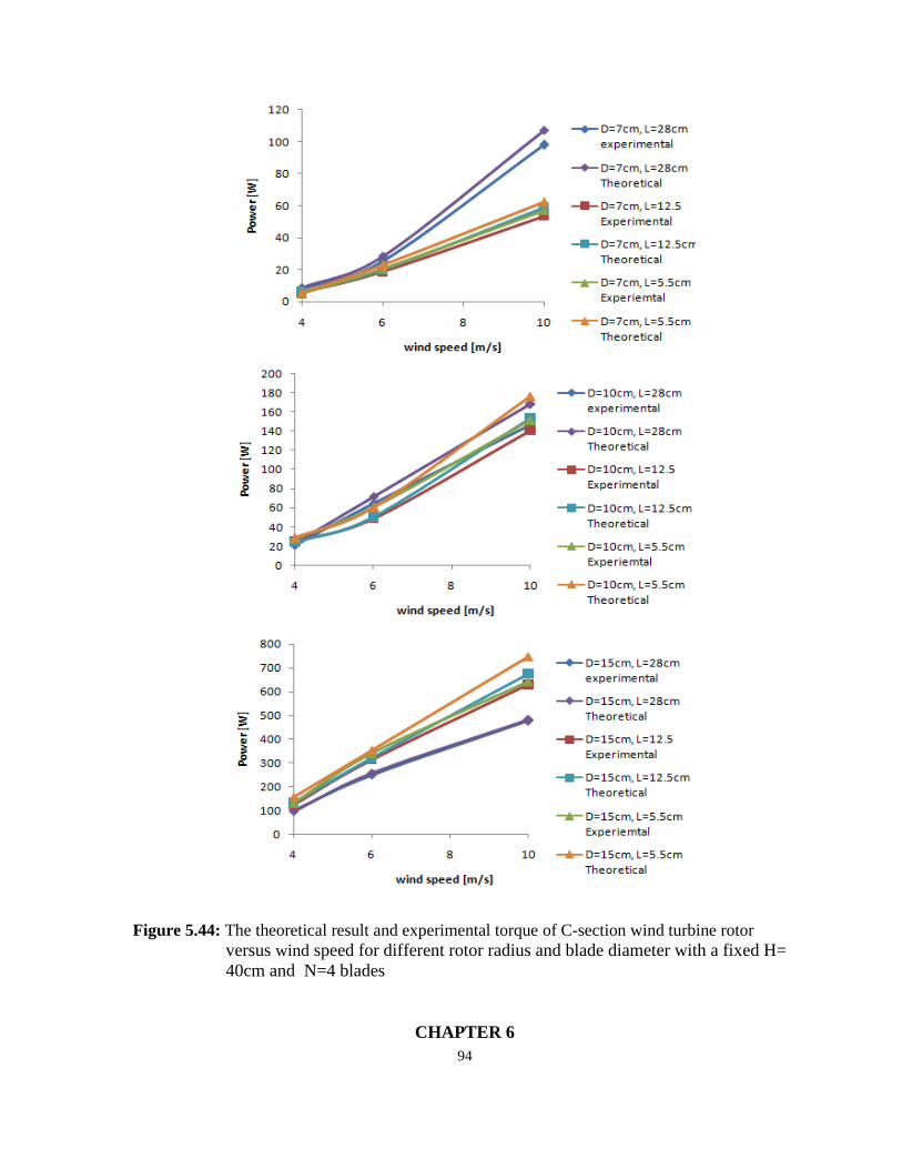
94
Figure 5.44: The theoretical result and experimental torque of C-section wind turbine rotor
versus wind speed for different rotor radius and blade diameter with a fixed H=
40cm and N=4 blades
CHAPTER 6
95
CONCLUSIONS AND FUTURE WORKS
Based on the research work, the aims and objections of the research project have been
achieved. The significant findings are summarized below.
6.1 Conclusions
The primary objective of this thesis is to analyze the effect of aerodynamic on the
performance of a prototype C-section vertical axis wind turbine and study the effect of
turbine geometry on the mechanical power produced at low wind speed.
The independent variables were wind speed, blade size, rotor diameter and blade number.
The different wind speeds were 4, 6 and 10 m/s. The blade lengths and diameters were 30
and 40 cm and 7, 10 and 15cm, respectively. The blades were made from PVC material. For
each blade length and blade diameter, there were six turbines, each with a different number
of blades, 2, 3, or 4. All tests were conducted indoors to reduce interfering wind and other
elements. The models of the C-section vertical axis wind turbine were tested under the same
environment. The main conclusions of this thesis are:
The performance of the turbine can be best evaluated by the theoretical study as
experimental evaluation consumes time and money. Another advantage of theoretical
study is that the experimental results can be verified if there is a geometrical
similarity between experimental and theoretical.
The increasing wind speed leads to increase the mechanical power of C-section
vertical axis wind turbine.
The mechanical power and torque of C-section rotor increases when blade number
and blade size increase.
From comparisons between the theoretical study and experimental test, it was found
that the absolute error is in range 0 and 15 percent.
From comparisons between 2, 3 and 4 blades, it was found that maximum power is
higher for 4 bladed of C-section rotor compared to 2 and 3 blades. The maximum
power is obtained blade height 40 cm, blade diameter 15cm, rotor radius 28cm and
wind speed 10 m/s.
96
For three blades of 10 cm diameter, was found to be more efficient than other
diameter and 2 and 4 blades.
From the results, it can be concluded that a four-bladed turbine should have about
double or more weight to turn compared to a two and three blade turbine of the same
size; but a four-bladed turbine has nearly quadrupled and double the pushing power
compared to two blade and three blade turbine of the same size, respectively.
It was also found that the largest bladed turbine shook violently during testing. This
shows that at high wind speeds, turbines with larger blades are unstable. This may
reduce the performance of the turbine, and it may break down.
It can be concluded that the C-section vertical axis wind turbine is capable of
producing electricity power even with low wind velocity for domestic used.
6.2 Future Works
Future work should include computer modeling of the rotor to study its flow profile and
predict its performance in terms of torque and power coefficient. The results of these
analyses could provide a better understanding of the fluid dynamic characteristics of our
wind turbine design. Ideally, CFD (Computational fluid dynamics) could be performed to
compare with the results from the testing performed with naturally occurring wind.
Another viable method would be to fabricate a scale model of the turbine to test in a wind
tunnel with controlled wind speeds and real-time flow profiles from smoke-dyed wind. These
studies will significantly advance the possibility for the widespread implementation of
vertical-axis wind turbines in the future.

97
REFERENCES
Abzug, M., & Larrabee, E. (2002). Airplane stability and control. Cambridge, UK:
Cambridge University Press.
Ali, M. (2013). Experimental Comparison Study for Savonius Wind Turbine of Two & Three
Blades At Low Wind Speed. International Journal of Modern Engineering Research,
3(5), 2978-2986.
Ali, M.H. (2012). Wind energy systems. Boca Raton, FL: Taylor & Francis.
Atta, T. (2015). Advantages and disadvantages of Vertical axis wind turbine Green
Mechanic. Retrieved May 5, 2015 from http://www.green-
mechanic.com/2013/04/advantages-and-disadvantages-of.html.
Burton, T. (2001). Wind energy handbook. Chichester New York: J. Wiley.
Dabiri, J. (2011). Potential order-of-magnitude enhancement of wind farm power density via
counter-rotating vertical-axis wind turbine arrays. Renewable Sustainable Energy, 3(4),
043-104.
D'Ambrosio, M., & Medaglia, M. (2010). Vertical Axis Wind Turbines: History, Technology
and Applications (master’s thesis). Halmstad university, Halmstad, Sweden.
Earnest, J. (2014). Wind power technology. New Delhi: PHI Learning.
Earnest, J. & Wizelius, T. (2011). Wind power plants and project development. New Delhi:
PHI Learning.
Eriksson, S. (2008). Direct driven generators for vertical axis wind turbines (Unpublished
doctoral dissertation). Uppsala university, Uppsala, Sweden.
Eriksson, S., Bernhoff, H., & Leijon, M. (2008). Evaluation of different turbine concepts for
wind power. Renewable And Sustainable Energy Reviews, 12(5), 1419-1434.
French, A. & Ebison, M. (1986). Introduction to Classical Mechanics. Dordrecht: Springer
Netherlands.
98
Gipe, P. (2003). Wind power. White River Junction, Vt.: Chelsea Green Pub. Co.
Gipe, P. (2009). Wind energy basics: a guide to home and community-scale wind energy
system White River Junction, Vt: Chelsea Green Pub. Co.
Gosselin, F., De Langre, E., & Machado-Almeida, B. (2010). Drag reduction of flexible
plates. Journal of Fluid Mechanics, 650, 319-341. doi:10.1017/s0022112009993673.
Graebel, W. (2001). Engineering fluid mechanics. New York: Taylor & Francis.
Gupta, R., & Biswas, A. (2011). CFD Analysis of flow physics and aerodynamic
performance of a combined three-bucket Savonius and three-bladed Darrieus turbine.
International Journal of Green Energy, 8(2), 209-233.
Gupta, R., Biswas, A., & Sharma, K. (2008). Comparative study of a three-bucket Savonius
rotor with a combined three-bucket Savonius-three-bladed Darrieus rotor. Renewable
Energy, 33(9), 1974-1981.
Hau, E. (2006). Wind turbines fundamentals, technologies, application, economics. Berlin
New York: Springer.
Hemami, A. (2012). Wind turbine technology. Clifton Park, NY: Delmar, Cengage Learning.
Hutchinson, J. (2005). Basic Flight Physics. Retrieved October 5, 2015 from
http://www.ucmp.berkeley.edu/vertebrates/flight/physics.html.
Kinzel, M., Mulligan, Q., & Dabiri, J. (2012). Energy exchange in an array of vertical-axis
wind turbines. Journal of Turbulance, 13, 38-54.doi: 10.1080/14685248.2012.712698.
Layton, J. (2006). How Wind Power Works. Retrieved October 6, 2015 from
http://science.howstuffworks.com/environmental/green-science/wind-power1.htm.
Manwell, J., McGowan, J. & Rogers, A. (2009). Wind energy explained : theory, design and
application. Chichester, U.K: Wiley.
Morshed, K., Rahman, M., Molina, G., & Ahmed, M. (2013). Wind tunnel testing and
numerical simulation on aerodynamic performance of a three-bladed Savonius wind

99
turbine. International Journal of Energy and Environmental Engineering, 4(1), 18.
Priya, S., O'Brien, W., & Tafti, D. (2013). Small-scale Wind Energy Portable Turbine
(SWEPT) (master’s thesis). Blacksburg university,Virginia, United State of America.
Rassoulinejad-Mousavi, M., Jamil, M., & Layeghi, M. (2013). Experimental Study of a
Combined Three Bucket H-Rotor with Savonius Wind Turbine. World Applied
Sciences. World Applied Sciences Journal 28 (2), 205-211.
Ribrant, J., & Bertling, L. (2007). Survey of failures in wind power systems with focus on
Swedish wind power plants during 1997-2005. Institute of Electrical and Electronics
Engineers, 22(1), 167-173.
Rivkin, D. & Silk, L. (2013). Wind power generation and distribution. Burlington, MA:
Jones & Bartlett Learning.
Rivkin, D. & Silk, L. (2013). Wind turbine technology and design. Burlington, MA: Jones &
Bartlett Learning.
Road,Hillington, A. (2016). HAWT, Horizontal axis wind turbines from Gaia wind, Their
advantages and disadvantages plus the effects of cyclic stress and vibration. Retrieved
Octobre 6, 2015 from http://www.azocleantech.com/article.aspx?ArticleID=191.
Roberson, J., & Crowe, C. (1997). Engineering fluid mechanics. New York: J. Wiley &
Sons.
Saha, U., & Rajkumar, M. (2006). On the performance analysis of Savonius rotor with
twisted blades. Renewable Energy, 31(11), 1776-1788.
Saha, U., Thotla, S., & Maity, D. (2008). Optimum design configuration of Savonius rotor
through wind tunnel experiments. Journal of Wind Engineering And Industrial
Aerodynamics, 96(8-9), 1359-1375.
Sheldahl, R., Feltz, L., & Blackwell, B. (1978). Wind tunnel performance data for two- and
three-bucket Savonius rotors. Journal of Energy, 2(3), 160-164.
100
Vogel, S. (1984). Drag and flexibility in sessile organisms. American Zoologist, 24(1), 37-44.
Fox, R., McDonald, A. & Pritchard, P. (2002). Introduction to fluid mechanics. New York:
Wiley.
Wenehenubun, F., Saputra, A., & Sutanto, H. (2014). An experimental study on the
performance of Savonius wind turbines related with the number of blades. Science
Direct, 68, 297–304. doi: 10.1016/j.egypro.2015.03.259.