the interfacial-area-based relative permeability function · pdf filepnnl-18792 prepared for...
TRANSCRIPT
PNNL-18792
Prepared for the U.S. Department of Energy Under Contract DE-AC05-76RL01830
The Interfacial-Area-Based Relative Permeability Function ZF Zhang R Khaleel September 2009
PNNL-18792
The Interfacial-Area-Based Relative Permeability Function ZF Zhang R Khaleel1 September 2009 Prepared for the U.S. Department of Energy under Contract DE-AC05-76RL01830 Pacific Northwest National Laboratory Richland, Washington 99352 _______________ 1 Fluor Government Group, Richland, Washington.


iii
Summary
CH2M Hill Plateau Remediation Company (CHPRC) requested the services of the Pacific Northwest National Laboratory (PNNL) to provide technical support for the Remediation Decision Support activity within the Soil and Groundwater Remediation Project. A portion of the support provided in fiscal year 2009 was used to develop an alternative approach to estimating the soil unsaturated hydraulic conductivity. This alternative approach uses the interfacial-area-based relative permeability (kr) model presented by Embid1 rather than the more traditional permeability models of Burdine2 and Mualem.3 The expectation was that the Embid kr model would improve the estimation of unsaturated conductivity for at least a subset of soil types. Three retention functions (Brooks and Corey,4 van Genuchten,5
and modified van Genuchten) were successfully combined with the Embid kr model. The kr relationship from the Brooks-Corey-Embid combination for the wetting phase is identical to that from the Brooks-Corey-Burdine combination. The general performance of the combined models is shown using typical hydraulic parameters. The relative permeability models for the wetting phase were further examined using two datasets from the literature. The results indicate that the interfacial-area-based model can describe the relative permeability of the wetting phase reasonably well. However, the comparison of the kr relationship from the van-Genuchten-Embid combination with that from the van-Genuchten-Mualem combination shows mixed performance results. Further tests are needed with a larger data set.
1 Embid, DSM. 1997. “Modeling Capillary Pressure and Relative Permeability for Systems with Heterogeneous Wettability.” Ph.D Dissertation, University of Texas, Austin, Texas. 2 Burdine, NT. 1953. “Relative permeability calculations from pore-size distribution data.” Petr. Trans. Am. Inst. Mining Metall. Eng. 198:71-77. 3 Mualem, Y. 1976. “A New Model for Predicting the Hydraulic Conductivity of Unsaturated Porous Media.” Water Resour. Res. 12:513-522. 4 Brooks, RH, and AT Corey. 1964. “Hydraulic Properties of Porous Media.” Hydrology Paper No. 3, Civil Engineering Department, Colorado State University, Fort Collins, Colorado. 5 van Genuchten, MTh. 1980. “A Closed-Form Equation for Predicting the Hydraulic Conductivity of Unsaturated Soils.” Soil Sic. Soc. Am. J. 44:892-898


v
Acknowledgments
This work is a portion of the Pacific Northwest National Laboratory’s Remediation Decision Support project managed by George V. Last. Funding for this work was provided by the CH2M HILL Plateau Remediation Company.


vii
Contents
Summary ........................................................................................................................................... iii Acknowledgments ............................................................................................................................... v
Contents ............................................................................................................................................vii 1.0 Introduction ............................................................................................................................. 1.1
2.0 Relative Permeability .............................................................................................................. 2.1
2.1 The Relative Permeability Relationship .......................................................................... 2.1
2.2 Brooks and Corey Water-Retention Model ..................................................................... 2.1
2.3 van Genuchten Water Retention Model .......................................................................... 2.4
2.4 Modified van Genuchten Water Retention Model .......................................................... 2.5
3.0 Test of the Interfacial-Area-Based Functions .......................................................................... 3.1
3.1 The van Genuchten (1980) Dataset ................................................................................. 3.1
3.2 The Rockhold et al. Dataset ............................................................................................ 3.8
3.3 Summary of Tests.......................................................................................................... 3.14
4.0 References ............................................................................................................................... 4.1
viii
Figures
2.1. Minimum Saturation in the krn Relationship Based on the Brooks and Corey (1964) Model. Points: numerical calculation; line: empirical relation Equation (2.6). ................................. 2.3
2.2. The Relative Permeability Function Based on the Brooks-Corey Retention Function. Solid line: λ = 2; dotted line: λ = 3; dashed line: λ = 10. ............................................................... 2.3
2.3. Minimum Saturation in the krn Relationship Based on the van Genuchten (1980) Model. Points: numerical calculation; line: empirical relation Equation (2.9). ................................. 2.5
2.4. The Relative Permeability Function Based on the van Genuchten (1980) Retention Function. Solid line: n = 2.5; dotted line: n = 10; dashed line: n = 10. ................................................. 2.5
2.5. Minimum Saturation in the krn Relationship. Points: numerical calculation; line: empirical relation Equation (2.13). .......................................................................................................... 2.7
2.6. The Relative Permeability Function Based on the Modified van Genuchten Retention Function. Solid line: ν = 2.5; dotted line: ν = 10; dashed line: ν = 10. ............................... 2.7
3.1. Observed and Calculated Soil Hydraulic Properties of the Hygiene Sandstone. (a) Observed and fitted water retention; (b) observed and predicted relative permeability. ......................... 3.3
3.2. Observed and Calculated Soil Hydraulic Properties of the Touchet Silt Loam G. E. 3. (a) Observed and fitted water retention; (b) observed and predicted relative permeability. .... 3.4
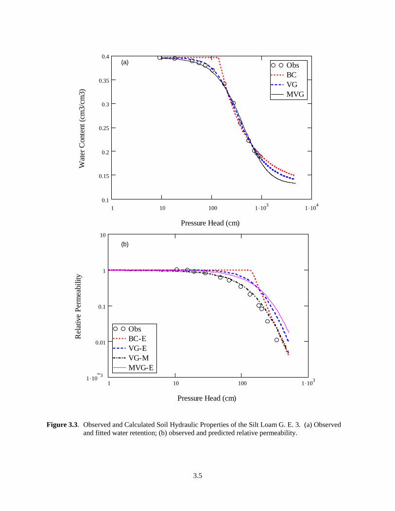
3.3. Observed and Calculated Soil Hydraulic Properties of the Silt Loam G. E. 3. (a) Observed and fitted water retention; (b) observed and predicted relative permeability. ......................... 3.5
3.4. Observed and Calculated Soil Hydraulic Properties of the Guelph Loam. (a) Observed and fitted water retention; (b) observed and predicted relative permeability. ................................ 3.6
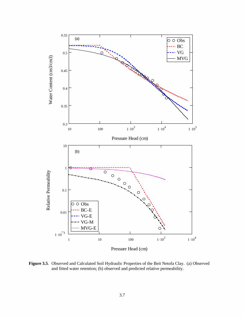
3.5. Observed and Calculated Soil Hydraulic Properties of the Beit Netofa Clay. (a) Observed and fitted water retention; (b) observed and predicted relative permeability. ......................... 3.7
3.6. Observed and Predicted Relative Permeability for the First Four Soils Listed in Table 3.1. (The numbers are the results of the linear regressions. r2 – coefficient of determination.) ..... 3.8
3.7. Observed and Calculated Soil Hydraulic Properties of the Column E Soil with Bulk Density of 1.6 g cm-3. (a) Observed and fitted water retention; (b) observed and predicted relative permeability. .......................................................................................................................... 3.10
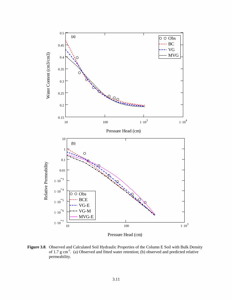
3.8. Observed and Calculated Soil Hydraulic Properties of the Column E Soil with Bulk Density of 1.7 g cm-3. (a) Observed and fitted water retention; (b) observed and predicted relative permeability. .......................................................................................................................... 3.11
3.9. Observed and Calculated Soil Hydraulic Properties of the Column F Soil with Bulk Density of 1.6 g cm-3. (a) Observed and fitted water retention; (b) observed and predicted relative permeability. .......................................................................................................................... 3.12
3.10. Observed and Calculated Soil Hydraulic Properties of the Column F Soil with Bulk Density of 1.7 g cm-3. (a) Observed and fitted water retention; (b) observed and predicted relative permeability. .......................................................................................................................... 3.13
3.11. Observed and Predicted Relative Permeability for the Soils Listed in Table 3.3. (The results of the linear regressions. r2 – coefficient of determination.) .................................................. 3.14

ix
Tables
3.1 Soil Hydraulic Parameters for the Example Soils Used by van Genuchten (1980) ...................... 3.13.2 Mean Squared Error of the Fitted Retention Curve and the Predicted Relative
Permeability .................................................................................................................................. 3.23.3 Soil Hydraulic Parameters for the Soils Studied by Rockhold et al. (1988) ................................. 3.93.4 Mean Squared Error of the Fitted Retention Curve and the Predicted Relative
Permeability .................................................................................................................................. 3.9


1.1
1.0 Introduction
The U.S. Department of Energy’s (DOE’s) “Report to the House and Senate Committees on Appropriations on Groundwater Vadose Zone Organization and Operations at the Hanford Site”1 indicates that future decisions on Hanford cleanup shall be based on an integrated understanding of how contaminants move through the environment. As the Plateau Remediation Contractor, CH2M HILL is required to develop a process to manage risk assessment activities across the Hanford Site, and maintain the key physical, chemical, and other parameters/assumptions associated with modeling the fate and transport of environmental contaminants for remediation decision support. To this end, CH2M HILL Plateau Remediation Company (CHPRC) has requested technical support from the Pacific Northwest National Laboratory (PNNL)2
Accurate description of soil relative permeability (kr) is necessary in modeling the unsaturated or multi-phase fluid flow in the vadose zone. In the past decades, the Burdine (1953) and Mualem (1976) relative permeability models, in combination with the different water-retention models, have been the primary models used to calculate the unsaturated hydraulic conductivity. Researchers have been searching for alternative models for a better description of the relative permeability. For example, Embid (1997) developed the relative permeability functions based the interfacial areas between the solid, the wetting, and the non-wetting phases, and the Carmen-Kozeny permeability equation (Carmen 1937). The expectation was that the Embid kr model would improve the estimation of unsaturated conductivity for at least a subset of soil types.
. A portion of the support requested in fiscal year 2009 was to develop an alternative approach to estimating the soil unsaturated hydraulic conductivity.
In this report, we document how we incorporated the Brooks and Corey model (1964), van Genuchten model (1980), and a modified van Genuchten water-retention model into the Embid (1997) relative permeability model. The models were examined using two datasets from the literature.
Section 2.0 of this report describes the relationships between soil relative permeability and saturation after incorporating the water retention functions into the Embid relative model and demonstrates the general performance of each model. Section 3.0 examines the interfacial-area-based relative-permeability relationships using data from the literature.
1 Rispoli JA. 2006. Letter to the Honorable Thad Cochran (Chairman, Senate Appropriations Committee) from James A. Rispoli (Assistant Secretary for Environmental Management, U.S. Department of Energy), March 29, 2006. 2 Pacific Northwest National Laboratory is operated by Battelle for the U.S. Department of Energy under Contract DE-AC05-76RL01830.

2.1
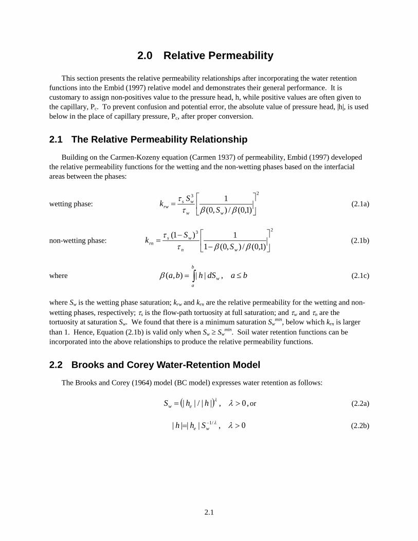
2.0 Relative Permeability
This section presents the relative permeability relationships after incorporating the water retention functions into the Embid (1997) relative model and demonstrates their general performance. It is customary to assign non-positives value to the pressure head, h, while positive values are often given to the capillary, Pc. To prevent confusion and potential error, the absolute value of pressure head, |h|, is used below in the place of capillary pressure, Pc, after proper conversion.
2.1 The Relative Permeability Relationship
Building on the Carmen-Kozeny equation (Carmen 1937) of permeability, Embid (1997) developed the relative permeability functions for the wetting and the non-wetting phases based on the interfacial areas between the phases:
wetting phase: 23
)1,0(/),0(1
=
ββττ
ww
wsrw S
Sk (2.1a)
non-wetting phase:
23
)1,0(/),0(11)1(
−
−=
ββττ
wn
wsrn S
Sk
(2.1b)
where badShbab
aw ≤= ∫ ,||),(β
(2.1c)
where Sw is the wetting phase saturation; krw and krn are the relative permeability for the wetting and non-wetting phases, respectively; τs is the flow-path tortuosity at full saturation; and τw and τn are the tortuosity at saturation Sw. We found that there is a minimum saturation Sw
min, below which krn is larger than 1. Hence, Equation (2.1b) is valid only when Sw ≥ Sw
min. Soil water retention functions can be incorporated into the above relationships to produce the relative permeability functions.
2.2 Brooks and Corey Water-Retention Model
The Brooks and Corey (1964) model (BC model) expresses water retention as follows:
( ) ,0,||/|| >= λλhhS ew or (2.2a)
0,|||| /1 >= − λλwe Shh (2.2b)

2.2
where he is the air-entry pressure-head and λ is a pore-size distribution parameter. Substituting Equation (2.2b) into (2.1c) derives the following:
( )
( )
λβ
λβ
λβ
λ
λλ
/11||)1,0(
/11||),0(
/11||),(
/11
/11/11
−=
−=
−−
=
−
−−
e
we
w
e
h
ShS
abhba
(2.3)
The Burdine tortuosity model is assumed:
2/ wws S=ττ
22 )1(/ wnns SS −==ττ (2.4)
Substituting Equations (2.3) and (2.4) into Equation (2.1) yields the relative permeability for the wetting and non-wetting phases:
wetting phase: λ/23+= wrw Sk (2.5a)
non-wetting phase:
min2/11
5
,)1(
)1(ww
w
wrn SS
SSk ≥
−−
= − λ (2.5b)
Equation (2.5) will be referred to as the Brooks and Corey-Embid (BC-E) model. Equation (2.5a) is the same as the formulation obtained with the Brooks and Corey (1964) retention function and the Burdine (1953) relative permeability model. The Sw
min may be estimated by the following empirical formula:
non-wetting phase: )exp(2min λ−≈wS (2.6)
The Swmin vs. λ curve is shown in Figure 2.1. Examples of krw and krn are shown in Figure 2.2.

2.3
0 2 4 6 8 101 .10 4
1 .10 3
0.01
0.1
1
Parameter Lamda
Min
imum
Wet
ting-
Flui
d Sa
tura
tion
Figure 2.1. Minimum Saturation in the krn Relationship Based on the Brooks and Corey (1964) Model.
Points: numerical calculation; line: empirical relation Equation (2.6).
0 0.2 0.4 0.6 0.81 .10 8
1 .10 7
1 .10 6
1 .10 5
1 .10 4
1 .10 3
0.01
0.1
1
Wetting-Fluid Saturation
Rel
ativ
e Pe
rmea
bilit
y
Non-Wetting Fluid
Wetting Fluid
Figure 2.2. The Relative Permeability Function Based on the Brooks-Corey Retention Function. Solid
line: λ = 2; dotted line: λ = 3; dashed line: λ = 10.

2.4
2.3 van Genuchten Water Retention Model
The van Genuchten (1980) model (VG model) expresses the water retention as follows:
[ ] or,||1 mnvgw hS α+=
(2.7a)
( ) nm
wvg
Sh/1/1 11|| −= −
α (2.7b)
where αvg is the inverse capillary length, n is a pore-size distribution parameter, and m = 1-1/n. After Equations (2.7) and (2.4) are substituted into Equation (2.1c), no closed-form expressions can be derived for krw and krn. To determine the behavior of krw and krn, we follow the same procedures as those of Niemet et al. (2002) by letting u = Sw
1/m, w = m – 1/n (= 1-2/n), and z = 1+1/n:
( )∫ −−−=
uwz duuumu
0
11 )(1),0(α
β , z > 0, w > 0 (2.8)
Here β(0,1) has the format of the beta function of w and z (Abramowitz and Stegun 1972, p. 258); β(0,Sw) is the incomplete beta function; and β(0,Sw)/β(0,1) is the regularized incomplete beta function of w and z (Abramowitz and Stegun 1972, p. 944, Equation 26.5.1). Because w > 0 is required in the beta function, 1-2/n > 0 and n > 2. This indicates that any value of n ≤ 2 will make Equation (2.8) not integratable. The relative permeability based on Equation (2.8) will be referred to as the van Genuchten-Embid (VG-E) model.
As in the Brooks and Corey model, there is a Swmin
for the VG-model-based krn relationship. The Swmin
may be estimated by the following empirical formula:
non-wetting phase: )exp(7min nSw −≈ (2.9)
The Swmin vs. n curve is shown in Figure 2.3. Examples of the krw and krn are shown in Figure 2.4.

2.5
2 3 4 5 60.01
0.1
1
Parameter n
Min
imum
Wet
ting-
Flui
d Sa
tura
tion
Figure 2.3. Minimum Saturation in the krn Relationship Based on the van Genuchten (1980) Model. Points: numerical calculation; line: empirical relation Equation (2.9).
0 0.2 0.4 0.6 0.81 .10 9
1 .10 8
1 .10 7
1 .10 6
1 .10 5
1 .10 4
1 .10 3
0.01
0.1
1
Wetting-Fluid Saturation
Rel
ativ
e Pe
rmea
bilit
y
Non-Wetting Fluid
Wetting Fluid
Figure 2.4. The Relative Permeability Function Based on the van Genuchten (1980) Retention Function.
Solid line: n = 2.5; dotted line: n = 10; dashed line: n = 10.
2.4 Modified van Genuchten Water Retention Model
For an integratable relationship of relative permeability, the van Genuchten (1980) model was modified as the modified van Genuchten (MVG) model. The format of the modified relationships is

2.6
identical to the VG model except m = 1+1/n and n > 0 (rather than m = 1-1/n and n > 1 as required by the VG model). To prevent confusion, Greek letters µ and ν are used here in the place of m and n, respectively:
[ ] or0,/11||1 >+=+= ννµαµνhS mvgw
(2.10a)
( ) 0,/1111||
/1/1 >+=−= − ννµα
νµw
mvg
Sh (2.10b)
where αmvg is the inverse capillary length, ν is the pore-size distribution parameter, and µ = 1+1/ν. Substituting Equations (2.10) into (2.1c) produces
( ) ( )[ ]( )[ ]
αβ
αβ
αβ
µµ
µµµµ
1)1,0(
111),0(
111),(
/1
/1/1
=
−−=
−−−=
ww SS
baba
(2.11)
Further substitution of Equations (2.11) and (2.4) into Equations (2.1a) and (2.1b) gives
wetting phase: ( )[ ] 0,/1111
2/1
5
>+=−+
= ννµµµ
w
wrw
S
Sk (2.12a)
non-wetting phase: ( ) 0,/11,,
1
)1( min2/1
5
>+=>−
−= ννµµµ ww
w
wrn SS
S
Sk (2.12b)
We refer to Equation (2.12) as the Modified-van Genuchten-Embid (MVG-E) model.
As in the previous models, there is a Swmin
for the MVG-E-based krn relationship. The Swmin may be
estimated by the following empirical formula:
non-wetting phase: )exp(2min ν−≈wS (2.13)
The format of Equation (2.13) is the same as that of Equation (2.6). The Swmin vs. n curve is shown in
Figure 2.5. Examples of the krw and krn are shown in Figure 2.6.

2.7
1 2 3 4 5 61 .10 3
0.01
0.1
1
Parameter nu
Min
imum
Wet
ting-
Flui
d Sa
tura
tion
Figure 2.5. Minimum Saturation in the krn Relationship. Points: numerical calculation; line: empirical
relation Equation (2.13).
0 0.2 0.4 0.6 0.81 .10 8
1 .10 7
1 .10 6
1 .10 5
1 .10 4
1 .10 3
0.01
0.1
1
Wetting-Fluid Saturation
Rel
ativ
e Pe
rmea
bilit
y
Non-Wetting Fluid
Wetting Fluid
Figure 2.6. The Relative Permeability Function Based on the Modified van Genuchten Retention
Function. Solid line: ν = 2.5; dotted line: ν = 10; dashed line: ν = 10.


3.1
3.0 Test of the Interfacial-Area-Based Functions
In this section, the interfacial-area-based relative-permeability relationships are examined using data from the literature. The retention parameters were fitted to the data. The fitted parameters were then used to predict the relative permeability of the corresponding soil. As a comparison, the results based on the van Genuchten (1980) retention function and the Mualem (1976) relative permeability model (VG-M) are also presented.
3.1 The van Genuchten (1980) Dataset
We digitized the soil water retention and relative permeability data for five soils in the van Genuchten (1980) paper. The saturated water content, θs, residual water content, θr, saturated hydraulic conductivity, Ks, and the fitted parameters for the BC, VG, and MVG water-retention models are summarized in Table 3.1. The observed and calculated hydraulic properties are shown in Figure 3.1 through Figure 3.5. For all of the soils except the Beit Netofa clay, all three models could fit the retention and predict the relative permeability reasonably well. However, for the Beit Netofa clay soil, while the fitting to the retention curve was generally acceptable, the prediction of the relatively permeability was either very poor (the BC-E, VG-M, and MVG-E models) or was not applicable (the VG-E model), because the fitted n parameter was less than 2. As pointed out by van Genuchten (1980), the quality of the dataset for the Beit Netofa clay soil may be questionable.
A comparison between the measurements and predictions of the ln(kr) for the first four soils in Table 3.1 is shown in Figure 3.6. The fitting MSE of the retention curve and the prediction MSE of krw are given in Table 3.2. On average, the VG and the MVG retention models had the least and greatest fitting error, respectively; the VG-M and MVG-E kr models had the least and greatest prediction error of relative permeability, respectively.
Table 3.1. Soil Hydraulic Parameters for the Example Soils Used by van Genuchten (1980). θs, θr, and Ks were from van Genuchten (1980); he, λ, αvg, n, αmvg, and ν are fitted parameters.
Soil Name
θs θr Ks he λ αvg n αmvg ν
cm3cm-3 cm/d cm - cm-1 - cm-1 -
Hygiene Sandstone 0.250 0.153 108.0 102.1 4.30 0.0082 9.90 0.0079 9.27
Touchet Silt Loam G.E. 3 0.469 0.190 303.0 148.4 2.64 0.0051 7.25 0.0048 6.65
Silt Loam G.E. 3 0.396 0131 4.96 141.2 0.768 0.00431 2.09 0.00154 1.438
Guelph Loam (Drying) 0.520 0.218 31.6 57.9 0.834 0.0120 2.08 0.00397 1.372
Beit Netofa Clay 0.446 0.0 0.082 243.9 0.121 0.00198 1.19 4.75E-6 0.548

3.2
Table 3.2. Mean Squared Error (MSE) of the Fitted Retention Curve and the Predicted Relative Permeability
Soil Name Fitting MSEθ (cm3cm-3) Prediction MSElnkr
BC VG MVG BC-E VG-E VG-M MVG-E
Hygiene Sandstone 0.0016 0.00057 0.066 0.101 0.104 0.034 0.109
Touchet Silt Loam G.E. 3 0.0015 0.00048 0.065 0.848 2.422 1.289 2.938
Silt Loam G.E. 3 0.0016 0.00012 0.035 0.675 0.677 0.097 0.827
Guelph Loam (Drying) 0.0020 0.00093 0.134 0.156 0.150 0.013 0.376
Beit Netofa Clay 0.0009 0.00042 0.00042 1.073 NA 0.404 6.548
Average 0.0015 0.00050 0.0601 0.571 0.838 0.367 2.160
MSEθ: MSE of Water Content; MSElnkr: MSE of log-transformed kr Retention Models: BC – Brooks and Corey (1964); VG – van Genuchten (1980); MVG – Modified van Genuchten Relative Permeability Models: BC-E – Brooks and Corey (1964) and Embid (1997); VG-E – van Genuchten (1980) and Embid (1997); VG-M – van Genuchten (1980) and Mualem (1976); MVG-E – Modified van Genuchten and Embid (1997)

3.3
10 100 1 .1030.14
0.16
0.18
0.2
0.22
0.24
0.26ObsBCVGMVG
Pressure Head (cm)
Wat
er C
onte
nt (c
m3/
cm3)
(a)
1 10 100 1 .1031 .10 3
0.01
0.1
1
10
ObsBC-EVG-EVG-MMVG-E
Pressure Head (cm)
Rel
ativ
e Pe
rmea
bilit
y
(b)
Figure 3.1. Observed and Calculated Soil Hydraulic Properties of the Hygiene Sandstone. (a) Observed
and fitted water retention; (b) observed and predicted relative permeability.

3.4
10 100 1 .103 1 .1040.15
0.2
0.25
0.3
0.35
0.4
0.45
0.5ObsBCVGMVG
Pressure Head (cm)
Wat
er C
onte
nt (c
m3/
cm3)
(a)
1 10 100 1 .1031 .10 3
0.01
0.1
1
10
ObsBC-EVG-EVG-MMVG-E
Pressure Head (cm)
Rel
ativ
e Pe
rmea
bilit
y
(b)
Figure 3.2. Observed and Calculated Soil Hydraulic Properties of the Touchet Silt Loam G. E. 3.
(a) Observed and fitted water retention; (b) observed and predicted relative permeability.
3.5
1 10 100 1 .103 1 .1040.1
0.15
0.2
0.25
0.3
0.35
0.4ObsBCVGMVG
Pressure Head (cm)
Wat
er C
onte
nt (c
m3/
cm3)
(a)
1 10 100 1 .1031 .10 3
0.01
0.1
1
10
ObsBC-EVG-EVG-MMVG-E
Pressure Head (cm)
Rel
ativ
e Pe
rmea
bilit
y
(b)
Figure 3.3. Observed and Calculated Soil Hydraulic Properties of the Silt Loam G. E. 3. (a) Observed
and fitted water retention; (b) observed and predicted relative permeability.

3.6
1 10 100 1 .103 1 .1040
0.1
0.2
0.3
0.4
0.5ObsBCVGMVG
Pressure Head (cm)
Wat
er C
onte
nt (c
m3/
cm3)
(a)
0 0.2 0.4 0.6 0.81 .10 8
1 .10 7
1 .10 6
1 .10 5
1 .10 4
1 .10 3
0.01
0.1
1
10
ObsBC-EVG-EVG-MMVG-E
Saturation
Rel
ativ
e Pe
rmea
bilit
y
(b)
Figure 3.4. Observed and Calculated Soil Hydraulic Properties of the Guelph Loam. (a) Observed and fitted water retention; (b) observed and predicted relative permeability.
3.7
10 100 1 .103 1 .104 1 .1050.3
0.35
0.4
0.45
0.5
0.55ObsBCVGMVG
Pressure Head (cm)
Wat
er C
onte
nt (c
m3/
cm3)
(a)
1 10 100 1 .103 1 .1041 .10 3
0.01
0.1
1
10
ObsBC-EVG-EVG-MMVG-E
Pressure Head (cm)
Rel
ativ
e Pe
rmea
bilit
y
(b)
Figure 3.5. Observed and Calculated Soil Hydraulic Properties of the Beit Netofa Clay. (a) Observed
and fitted water retention; (b) observed and predicted relative permeability.

3.8
-12
-10
-8
-6
-4
-2
0
-12 -10 -8 -6 -4 -2 0
Pred
icte
d ln
(kr)
Measured ln(kr)
BC-E
VG-E
VG-M
MVG-E
Linear (BC-E)
Linear (VG-E)
Linear (VG-M)
Linear (MVG-E)
1:1 line
r2 Slope Intercept
0.907 1.130 0.284
0.812 1.098 0.195
0.912 1.114 0.092
0.751 1.038 0.136
Figure 3.6. Observed and Predicted Relative Permeability for the First Four Soils Listed in Table 3.1.
(The numbers are the results of the linear regressions. r2 – coefficient of determination.)
3.2 The Rockhold et al. Dataset
Rockhold et al. (1988) measured the water retention and hydraulic conductivity of repacked soil from the 300-N lysimeter site (formerly called the Buried Waste Test Facility), and the data were summarized in their Appendix A.1. After assuming that θr was half of their measured minimum and θ and θs was the maximum θ, we fitted the rest of the retention parameters to the retention data. Then, the parameters were used to predict the measured relative permeability. The pre-determined parameters and the fitted parameters are summarized in Table 3.3. The observed and calculated hydraulic properties are shown in Figure 3.7 through Figure 3.10. The models can describe the hydraulic properties of the sandy soil quite well.
A comparison between the measurements and predictions of the ln(kr) for the soils in Table 3.3 is shown in Figure 3.11. The fitting MSE of the retention curve and the prediction MSE of kw are given in

3.9
Table 3.4. On average, the BC and the MVG retention models had the least and greatest fitting error, respectively; the VG-E and VG-M models had the least and greatest prediction error of relative permeability, respectively.
Table 3.3. Soil Hydraulic Parameters for the Soils Studied by Rockhold et al. (1988). θs and Ks were from Rockhold et al. (1988); θr was assumed to be half of the measured minimum θ; he, λ, αvg, n, αmvg, and ν are fitted parameters.
Soil Name
θs θr Ks he λ αvg n αmvg ν cm3cm-3 cm/s cm cm-1 - cm-1 -
Soil E with ρb = 1.6 g cm-3 0.435 0.043 4.62E-3 11.7 1.09 0.067 2.25 0.025 1.29
Soil E with ρb = 1.7 g cm-3 0.400 0.042 7.12E-3 12.1 0.812 0.058 2.01 0.013 0.973
Soil F with ρb = 1.6 g cm-3 0.422 0.055 9.78E-3 12.97 1.19 0.058 2.49 0.028 1.59
Soil F with ρb = 1.7 g cm-3 0.386 0.043 8.91E-3 12.3 0.816 0.058 2.01 0.013 0.962
ρb = bulk density
Table 3.4. Mean Squared Error of the Fitted Retention Curve and the Predicted Relative Permeability
Soil Name
Fitting MSEθ (cm3 cm-3) Prediction MSElnkr
BC VG MVG BC-E VG-E VG-M MVG-E
Soil E with ρb = 1.6 g cm-3 0.0012 0.0021 0.328 1.015 0.803 1.191 0.876
Soil E with ρb = 1.7 g cm-3 0.0015 0.0022 0.344 0.577 0.307 1.067 0.480
Soil F with ρb = 1.6 g cm-3 0.0008 0.0018 0.292 0.703 0.720 0.786 0.867
Soil F with ρb = 1.7 g cm-3 0.0012 0.0021 0.340 0.218 0.145 0.592 0.771 Average 0.0012 0.0021 0.326 0.628 0.494 0.909 0.749
MSEθ: MSE of water content; MSElnkr: MSE of log-transformed relative permeability Retention Models: BC – Brooks and Corey (1964); VG – van Genuchten (1980); MVG – Modified van Genuchten Relative Permeability Models: BC-E – Brooks and Corey (1964) and Embid (1997); VG-E – van Genuchten (1980) and Embid (1997); VG-M – van Genuchten (1980) and Mualem (1976); MVG-E – Modified van Genuchten and Embid (1997)

3.10
10 100 1 .1030.14
0.16
0.18
0.2
0.22
0.24
0.26ObsBCVGMVG
Pressure Head (cm)
Wat
er C
onte
nt (c
m3/
cm3)
(a)
10 100 1 .1031 .10 8
1 .10 7
1 .10 6
1 .10 5
1 .10 4
1 .10 3
0.01
0.1
1
10
ObsBCEVG-EVG-MMVG-E
Pressure Head (cm)
Rel
ativ
e Pe
rmea
bilit
y
(b)
Figure 3.7. Observed and Calculated Soil Hydraulic Properties of the Column E Soil with Bulk Density
of 1.6 g cm-3. (a) Observed and fitted water retention; (b) observed and predicted relative permeability.
3.11
10 100 1 .103 1 .1040.15
0.2
0.25
0.3
0.35
0.4
0.45
0.5ObsBCVGMVG
Pressure Head (cm)
Wat
er C
onte
nt (c
m3/
cm3)
(a)
10 100 1 .1031 .10 7
1 .10 6
1 .10 5
1 .10 4
1 .10 3
0.01
0.1
1
10
ObsBCEVG-EVG-MMVG-E
Pressure Head (cm)
Rel
ativ
e Pe
rmea
bilit
y
(b)
Figure 3.8. Observed and Calculated Soil Hydraulic Properties of the Column E Soil with Bulk Density of 1.7 g cm-3. (a) Observed and fitted water retention; (b) observed and predicted relative permeability.

3.12
10 100 1 .1030.1
0.15
0.2
0.25
0.3
0.35
0.4ObsBCVGMVG
Pressure Head (cm)
Wat
er C
onte
nt (c
m3/
cm3)
(a)
10 100 1 .1031 .10 6
1 .10 5
1 .10 4
1 .10 3
0.01
0.1
1
10
ObsBCEVG-EVG-MMVG-E
Pressure Head (cm)
Rel
ativ
e Pe
rmea
bilit
y
(b)
Figure 3.9. Observed and Calculated Soil Hydraulic Properties of the Column F Soil with Bulk Density of 1.6 g cm-3. (a) Observed and fitted water retention; (b) observed and predicted relative permeability.

3.13
10 100 1 .1030
0.1
0.2
0.3
0.4
0.5ObsBCVGMVG
Pressure Head (cm)
Wat
er C
onte
nt (c
m3/
cm3)
(a)
10 100 1 .1031 .10 7
1 .10 6
1 .10 5
1 .10 4
1 .10 3
0.01
0.1
1
10
ObsBCEVG-EVG-MMVG-E
Pressure Head (cm)
Rel
ativ
e Pe
rmea
bilit
y
(b)
Figure 3.10. Observed and Calculated Soil Hydraulic Properties of the Column F Soil with Bulk Density of 1.7 g cm-3. (a) Observed and fitted water retention; (b) observed and predicted relative permeability.

3.14
-16
-14
-12
-10
-8
-6
-4
-2
0
-16 -14 -12 -10 -8 -6 -4 -2 0
Pred
icte
d ln
(kr)
Measured ln(kr)
BC-E
VG-E
VG-M
MVG-E
Linear (BC-E)
Linear (VG-E)
Linear (VG-M)
Linear (MVG-E)
1:1 line
r2 Slope Intercept
0.989 1.044 -0.373
0.983 1.030 -0.231
0.981 0.997 -0.792
0.954 0.947 -0.297
Figure 3.11. Observed and Predicted Relative Permeability for the Soils Listed in Table 3.3. (The results
of the linear regressions. r2 – coefficient of determination.)
3.3 Summary of Tests
The relative permeability models for the wetting phase were examined using two datasets from van Genuchten (1980) and Rockhold et al. (1988). The results indicate that the interfacial-area-based model can describe the relative permeability of the wetting phase reasonably well. However, the comparison of the kr relationship of the van-Genuchten-Embid combination with that of the van-Genuchten-Mualem combination show mixed performance results. Further tests are needed with a larger dataset. Attention should be paid to low kr values under relative dry conditions.
4.1
4.0 References
Abramowitz M and IE Stegun. 1972. “Handbook of Mathematical Functions with Formulas, Graphs, and Mathematical Tables.” National Bureau of Standards Applied Mathematics Series 55, tenth printing, U.S. Government Printing Office, Washington, D.C.
Brooks RH, and AT Corey. 1964. “Hydraulic Properties of Porous Media.” Hydrology Paper No. 3, Civil Engineering Department, Colorado State University, Fort Collins, Colorado.
Burdine NT. 1953. Relative permeability calculations from pore-size distribution data. Petr. Trans. Am. Inst. Mining Metall. Eng. 198:71-77.
Carman PC. 1937. “Fluid Flow through a Granular Bed.” Trans. Inst. Chem. Engrs. 15, 150-156.
Embid DSM. 1997. “Modeling Capillary Pressure and Relative Permeability for Systems with Heterogeneous Wettability.” Ph.D Dissertation, University of Texas, Austin, Texas.
Mualem Y. 1976. “A New Model for Predicting the Hydraulic Conductivity of Unsaturated Porous Media.” Water Resour. Res. 12:513-522.
Niemet MR, ML Rockhold, N Weisbrod, and JS Selker. 2002. “Relationships Between Gas-Liquid Interfacial Surface Area, Liquid Saturation, and Light Transmission in Variably Saturated Porous Media.” Water Resour. Res. 38(8),10.1029/2001WR000785.
Rockhold ML, MJ Fayer, and GW Gee. 1988. Characterization of Unsaturated Hydraulic Conductivity at the Hanford Site. PNL-6488, Pacific Northwest National Laboratory, Richland, Washington.
van Genuchten MTh. 1980. “A Closed-Form Equation for Predicting the Hydraulic Conductivity of Unsaturated Soils.” Soil Sic. Soc. Am. J. 44:892-898.


PNNL-18792
Distribution
No. of No. of Copies Copies
Distr.1
Onsite CH2M HILL Plateau Remediation
Company BA Williams (PDF) Fluor Government Group R Khaleel (PDF)
Pacific Northwest National Laboratory MJ Fayer (PDF) GV Last (PDF) ML Rockhold (PDF) AL Ward (PDF) ZF Zhang (PDF)
