the inventions of willi von unruh and hans coler by cyril smith, chava … · 2012. 11. 11. ·...
TRANSCRIPT
chava - public article www.chavascience.com www.chavaenergy.com
The British Intelligence Report.
At the cessation of World War 2 the three allies, USA, Russia and UK, separately performed intelligence gathering in Germany to reap the benefits of German scientific endeavours. One such exercise is reported in the British Intelligence Objectives Sub-committee (BIOS) Final Report No.1043 “The invention of Hans Coler relating to an alleged new source of power”. The report was declassified in 1979 and is now widely available on the internet.
Although many copies were originally made, copy No. 306 is held in the UK Imperial War Museum at its Duxford location. Until recently this was thought to be the only surviving copy, but another copy has been discovered in the UK National Archives buried within a file. This shows that copy No. 306 is a valid version of the original report and has not been subjected to any subsequent changes.
The interrogation team consisted of R. Hurst from the then Ministry of Supply (which later became part of the Ministry of Defence) and Captain R. Sandberg, Norwegian Army. It is now known that Sandberg was there merely as an observer to protect his interest in the inventions, Unruh and Coler having received funds from Sandberg before the War, and the report was probably written solely by Hurst. The report mentions two inventions, (a) the Magnetstromapparat which Coler replicated for the interrogation team and (b) the Stromerzeuger of which no working model then existed.
Because the report gave details of the construction of the Magnetstromapparat there have since been various attempts at replicating this and these are widely reported. However until now there has been only speculation regarding the design of the Stromerzeuger.
UK National Archive Data
Recently, in the UK National Archives, another file was discovered by Professor Gwyn Hocking who brought this to the attention of Chava. This file came from the top level of the Ministry of Supply and dealt exclusively with claims for the rights to Coler’s inventions, initially by Sandberg but later by Dr. Modersohn.
Sandberg’s claim was made via the Norwegian
Embassy which brought it to the attention of the UK Government, thus involving the then prime Minister Mr. Atlee, so there was pressure from this top level to get the issue resolved.
The file reveals that following on from the replication Coler performed while in Germany, he then moved to the UK where he was given a six-month contract to build a Stromerzeuger, with a salary of £500 per annum (see Annex 4). This was at the request of people at the technical level but it is clear that the higher Government officials were of the opinion the exercise was a waste of money, and they were concerned that should the knowledge of this contract get leaked to the press the UK would be the laughing stock of the world.
At the end of the six months Coler claimed some success, but this was repudiated by those who were convinced the device couldn’t possibly work and who claimed Coler could have obtained his waveforms from within an oscilloscope. However those scientists with technical control of Coler’s work thought it worth pursuing further and permission was given for a further six month contract. Unfortunately Coler died of a heart attack before this could be taken up and the work went no further. Coler’s Stromerzeuger replication was sold to Sandberg.
We have photocopied this data and conducted further research revealing more about the history of these inventions and more importantly technical data on Unruh’s or Coler’s Strömerzeuger (hereafter called the “S” machine to differentiate it from their Magnetströmapparat, the “M” machine). This present paper traces the history and discloses the latest knowledge on the S machine.
History
The story starts in 1920 with a patent application by Robert Norrby (a Swedish national) entitled “Method for Generating Electricity”. The UK Patent Specification 159,487 states:
“The application for a Patent has become void. This print shows the specification as it became open to public inspection”
Copies of the specification could be obtained at a cost of one shilling. That same year in Berlin, Willi von Unruh demonstrated
equipment powered by small Leclanche cells that lit five 1000 candlepower lamps over a longer time interval than could be accounted for by the energy available from the batteries. This was widely reported in the newspapers, we have copies from the UK Daily Chronicle, the New York Times and the New Zealand Ashburton Guardian.
From the description we now believe this was the same invention as claimed by Norrby and the first demonstration of the S machine.
Unruh said he had developed the equipment over the previous five years which raises the question, did Unruh use Norrby as a front man to gain a patent, did Norrby steal Unruh’s work or vice versa? During the demonstration Unruh claimed the excess energy came from splitting of the atom (this was shortly after Einstein’s E=mc2 revelations!) and was pilloried for this by the scientific establishment who were certain the machine was a hoax, despite no one being able to prove that. Unruh was jailed.
German archives reveal that Unruh and Coler were in collaboration by 1925, then one year later we find Coler (not Unruh) demonstrating an overunity 10W S machine to three Professors (W. O. Schumann, M. Kloss and R. Franke), translations of their findings being given in the BIOS report. They used their own instruments and verified the machine produced more power into its load lamps than was supplied by the batteries. They could not explain where the excess energy came from but were convinced the machine was not a hoax.
However no doubt fearing for their reputations they forbade the publication of their findings. We can only surmise that Unruh, in the light of his unfortunate 1920 experience, used Coler as his front man for these demonstrations. In 1933 Coler and Unruh created a more powerful 70W S machine and also developed their M machine. Four years later a 6KW version of the S machine was produced. This was destroyed by bombs during WW2. It is believed that Unruh died around 1937.
That Unruh was really the brains behind the developments is supported by information in the National Archives of Norway. When Unruh and Coler took money from two different investors, one of them Norwegian, there resulted some legal wrangling and the following is an extract from a recent letter to Professor Hocking.
The Inventions of Willi von Unruh and Hans ColerBy Cyril Smith, Chava Energy.
November 2012
Late in 2010 Chava Energy uncovered a treasure trove of new information on Hans Coler, his devices and their true origins - Willi von Uruh. This short article gives a glimpse behind the curtain of some of the information Chava has on this topic. For more information about Chava Energy our vision and projects visit - www.chavaenergy.com.This article appears on www.chavascience.com and correspondance should be directed to [email protected]

chava - public article www.chavascience.com www.chavaenergy.com
“In the archives of the Norwegian ministry of foreign affairs, “Utenriksdepartementet”, there is a file with the signature H4 AII 5/34 in the series Dk box 3309 containing a large number of documents from July 1934 to December 1938 regarding a court case against dir. Reinert Sandberg and others involved in Norwegian financing of an invention in electric energy. The inventor’s name was von Unruh, but his assistant, Hans Coler, seems to have kept the patent until it was confiscated by the Nazi authorities.”
Being Unruh’s assistant perhaps explains why, after Unruh’s death, Coler seems to be out of his depth in explaining and demonstrating the workings of his apparatus. It may be noted that Sandberg accompanied the UK intelligence officer when Coler was interrogated after WW2, presumably to protect his interest in the inventions.
During WW2 the German Admiralty took an interest in the S machine as a possible source for charging submarine batteries and in 1943 we find Coler co-operating with Dr H. Frohlich in experiments. They were not able to replicate a working machine so their research examined the current and voltage waveforms of inductive and resonant circuits. Surprisingly, although in 1926 Professor Kloss had commented on the unusual feature in the S machine of current passing through the iron cores of electromagnets as being the likely source of the excess energy, the Coler-Frohlich research did not specifically examine this merely stating it as an unsolved problem.
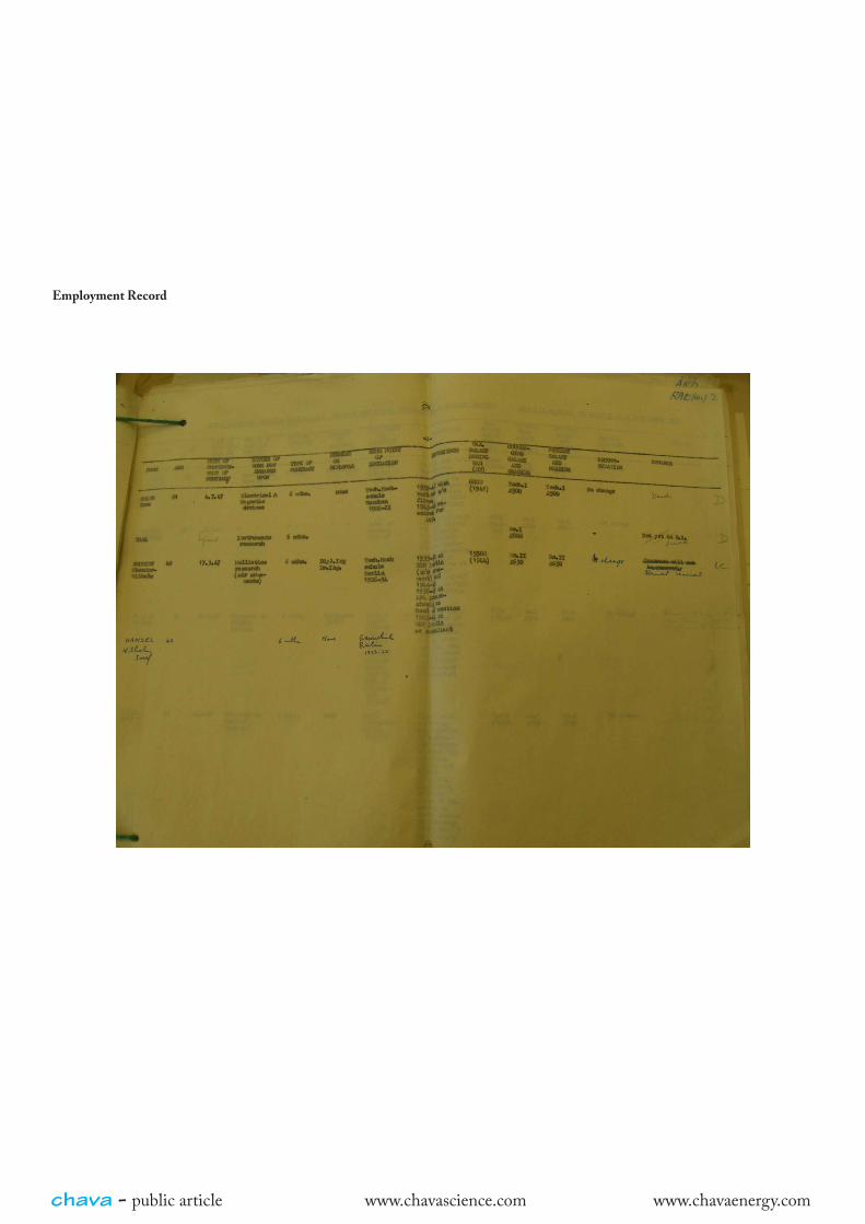
After WW2 in 1945 Coler was interrogated by the British and contracted to replicate the M machine, the results being reported in the Intelligence report. Information from the UK National Archives reveals that after WW 2 German nationals were employed in the UK under two different schemes. Those employed in industry were there under the “Darwin Panel” so named because its chairman was Sir Charles Darwin (descendent of the famous Charles Darwin). Those employed in military activities were there under a scheme controlled by the Deputy Chief of Staff (DCOS). Coler was employed in the UK under the latter scheme in 1947. His intention was to move to Norway at the end of his contract. Coler was given a six month contract to build his Stromerzeuger, starting on 4th July 1947. He was given a room and facilities, including a Polish assistant, at the Signals Research and Development Establishment (SRDE) at Christchurch on the South coast, but he was supervised from the Royal Aircraft Establishment (RAE) some 70 miles North (presumably at that time RAE did not have the electronic facilities needed for his work). He claimed partial success which was later disputed by the men at the top who thought the whole exercise was a waste of time and money. Those closer to him thought it worth continuing (see Annex 5) and in December 1947 permission was given for a six month extension. However before that could take place Coler died of a heart attack while staying
at a small hotel near to the RAE. His death is registered in the Registration District of Aldershot, Sub-district Farnborough in the county of Southampton (later renamed Hampshire) and the certificate reveals his full name as Hermann Carl Gustav Hans Coler (see Annex 1 for a copy of the death certificate). He died on 20th December 1947 aged 61. His descendant is named in the Archive files as his sister Eva Coler with an address Berlin-Friedmenau, Kaiser Allee 112, Gartenhaus III, with correspondence to be sent via Paulus Asta Coler, 26 Diana Str. Michendorf 1B Mark, Berlin Brandenborg. After his death there were applications from Reinert Sandberg and Dr. Modersohn who had both supplied financial backing to Coler during the 1930’s and who both claimed rights to his inventions. What remained of the apparatus was eventually sold to Sandberg.
Stromerzeuger Technical Data.
There are a number of descriptions of the S machine each of which adds to our knowledge of its construction.
The newspaper articles reporting Unruh’s 1920 demonstration describe “a wooden box about 4 ft long, 2 ft wide and 3 ft high. Within the box were two rows of copper plates.”
Appendices II and III of the Intelligence report are translations of reports by Professors Kloss and Schumann on their 1926 examinations of the S machine exhibited by Coler. These have lost something in the translations, one report uses the word “spool” in the recognized sense of a coil while the other uses “spool” for the manner in which copper plates are connected.
Appendix II describes “a double-row system of copper plates, a double-row system of flat spools and a system of electro-magnets to whose cores silver wires are attached and through which branch currents of the plate system are conducted.”
Appendix III states “two parallel connected spools…one of these spools is composed of copper sheets, the other of thin…wires running parallel… to the plates…inter-communications are connected between parallel windings of the two halves of the plate spool which contain iron rods with silver connections.”
We begin to see a picture of a stack of copper plates interleaved with flat coils and some special connections between some of the plates where the current flows through the iron-rod cores of electromagnets. The “silver” connections to those iron rods seem mysterious until we later discover that the conduction also passes through thin permanent magnets connected to the iron rods. It seems reasonable to conclude that the “silver wire” seen by the professors was really permanent magnet material used as a conductor.
Appendix IV reports on the work of Coler and Dr. Frohlich for the German Admiralty, and uses different terminology perhaps again wrongly translated. Here the electromagnets that contain the iron rods are called transformer coils and we find “the transformer coils, connected between the anchor plates, are connected in a peculiar way through thin permanent magnet rods. Their main object seems to be to pre-magnetize the transformer cores.”
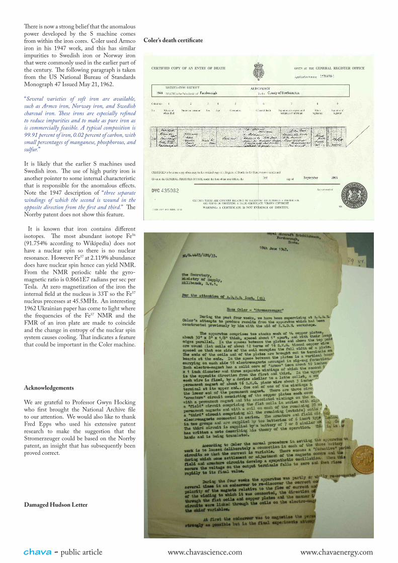
The UK National Archives contain a letter describing the device Coler was building in 1947 and this provides a much clearer picture. That letter has been much handled over the years and is in poor state (see Annex 2). By adjusting character spacing to match that of the typewriter used it has been possible to make an intelligent guess at the missing words, see Annex 3. The pertinent paragraph is reproduced here, and it should be noted this is a description by an observer who did not necessarily know the intimate details and assumed connections to the iron cores were connections to the coils on those cores.
The apparatus comprises two stacks each of 14 copper plates, about 30” x 8” x 1/8” thick, spaced about 1” apart, and with their longest edges parallel. In the spaces between the plates and above the top pair are wound flat coils of about 12 turns of 16 S.W.G. tinned copper wire spaced so that one side of the coil occupies the full width of a plate. The ends of the coils and of the plates are brought out to terminals on boards at the ends. In the space between the plates is a vertical board carrying on each side 28 electromagnets arranged in zig-zag formation. Each electro-magnet has a solid core of “Armco” iron about 10 inches long x 1 inch diameter and three separate windings of which the second is wound in the opposite direction from the first and third. In the upper windings to each wire is fixed, by a device similar to a lathe collet, a small permanent magnet of about 16 S.W.G. piano wire about 3 inches from the terminal at the upper end. One end of one of the windings is connected to the lower end of the permanent magnet. There are three circuits, an “armature” circuit consisting of the copper plates each connected with a permanent magnet and its associated windings on the electromagnet, a “field” circuit comprising the flat coils in series with eight of the permanent magnets and with a coil on each of the remaining 28 magnets and a “third” circuit comprising all the remaining (outside) coils and the electromagnets connected in series. The armature and field circuits come in two groups and are supplied by two batteries of 6 inert type Leclanche. The third circuit is supplied by a battery of 7 or 8 similar cells.
Finally from the National Archives there is a letter written after Coler’s death listing and costing the equipment to be sold to Sandberg. This provides more insight into the actual dimensions of some of the parts such as.
• Copper sheets 8” x 48” x 0.108”,• Soft iron cores ¾” dia. x 8” long,• Coils each containing approx. 1 lb of 0.064”
dia. enam. wire

chava - public article www.chavascience.com www.chavaenergy.com
It is quite clear that two stacks of copper sheets of these dimensions separated by a reasonable gap sufficient to contain the electromagnets had exactly the footprint of the box shown by Unruh in 1920. The stack being 14 layers high exactly matched the stack in the Norrby patent, and from the known weight and wire diameter of each flat coil it has been possible to estimate the number of turns for each as 10, again exactly matching the patent. These matching numbers and the fact that the construction details also match, including current flowing through the iron cores of 28 electromagnets, cannot be coincidence, there can be no doubt that the S machine is based on the Norrby patent. We are grateful to Fred Epps who brought this to our attention. The Norrby patent itself gives us the interconnections between the plates and the coils, so we now have a clear picture of the S machine. Note the use of enameled copper wire for the flat coils. Figure 1 is an image taken from the Norrby 1920 patent showing a cross-section of the stack.
Figure1. Taken from Norrby Patent
The electromagnets mounted on the vertical board are depicted here much smaller than those used by Coler in 1947, presumably the larger cores were necessary for greater power output. Also the Norrby design does not include the later use of thin permanent magnets carrying current into the iron cores.
Figure 2. Central Board showing Electro-magnets Figure 2 shows views of the central board housing the electromagnets. Figure 3 is the circuit taken from the Norrby patent which only shows five layers whereas the full system used 14 layers. The load resistor is not shown in the original patent but has been added in its rightful position as determined by the Schumann/Kloss reports. Not shown are the electromagnets; their coils are all connected in series and energized from a third battery also not shown. Each connection marked p between left and right plates in each layer actually passes through two iron cores in series.

chava - public article www.chavascience.com www.chavaenergy.com
Discussion
For some time we have been struggling to bring some common sense to what we now know about the S machine. Our problem has been reconciling the fact exposed by the tests performed in 1926 by Professors Kloss and Schumann, that the anomalous output is predominantly DC, with the wiring diagram yielded by the 1920 Norrby patent specification which shows the cross-connections between the rows of plates. Those cross-connections include the iron cores where the anomalous voltage is thought to appear, but being
connected to an otherwise isolated plate these cannot at first sight support the production of direct current. The Norrby patent clearly suggests the system creates high frequency AC, so how can a capacitively coupled AC produce DC without some form of rectification? There is a clue to this feature in Coler’s attempt to explain the workings of the S machine as reported in the British Intelligence report Appendix I. Coler talks about “separation of charges”, with the charges being “magnetically
polarised” due to passing through magnets, but only for current in one direction. For the reverse current “the magnets do not exert a polarising effect”. So Coler was aware of a rectification effect. Although Coler incorrectly viewed this magnetic polarization as turning conduction electrons into isolated S poles, we now know that magnetized conductors do contain spin-polarized (magnetic dipole) electrons, hence a current of such electrons transports magnetization (magnons). Thus for an alternating current spin-polarized electrons travelling from the permanent magnet into the soft iron would transport magnons only on one polarity of half cycle. It would seem that Unruh or Coler discovered some aspects of the relatively new science of spintronics. It may be noted that the cores, acting as voltage sources for only one direction of current through them, and being almost a short circuit for the reverse current, pulse the high frequency AC resonant circuit in a half-cycle fashion requiring a minimum of two cores acting in push-pull to do this over a full cycle. Again quoting Coler from the intelligence report,
“A single stage cannot be effective but two stages connected so that the numbers of effective North and South poles are equal will provide a basic working arrangement. More double stages can then be added to provide higher output.”
It is reported that the output from the S machine was interrupted DC at 180KHz rate (perhaps being full-wave rectified 90KHz), so we are faced with verifying that the now known coil and plate geometry can resonate at this relatively low RF. Each layer consists of a flat 10 turn coil of rectangular form about 48 inches long and 24 inches wide using 0.064 inch diameter enameled copper wire. The coil is close bonded to two side-by side copper plates each 48 inches long and 8 inches wide so that each plate has 10 parallel conductors running along its length. With each conductor being widely separated (~0.8 inch) from adjacent ones, it can be considered as a single conductor close to a ground-plane and we can estimate the distributed capacitance using transmission line theory, with its image in the ground plane forming a twin wire line. Separated from the ground-plane by perhaps just the thickness of the enamel, the impedance of the line would be quite low, about 15 Ohms, yielding a distributed capacitance of about 200pF/m. Since each turn of the flat coil has 8ft of wire against the ground-planes, and there are 10 turns, we have 4,800pF per coil. Total capacity for the stack of 14 coils is then 67,200pF. This value can easily account for the low frequency. Another approach is to consider the total time delay along the entire length of the conductor in the 14 coils and assume this to be a quarter wave transmission line. This length is about 336m, hence the wavelength is 1344m yielding a frequency of 223KHz. This is close to the 180KHz figure quoted.
LOADLOAD
Figure 3. Circuit taken from Norrby Patent
chava - public article www.chavascience.com www.chavaenergy.com
There is now a strong belief that the anomalous power developed by the S machine comes from within the iron cores. Coler used Armco iron in his 1947 work, and this has similar impurities to Swedish iron or Norway iron that were commonly used in the earlier part of the century. The following paragraph is taken from the US National Bureau of Standards Monograph 47 Issued May 21, 1962.
“Several varieties of soft iron are available, such as Armco iron, Norway iron, and Swedish charcoal iron. These irons are especially refined to reduce impurities and to make as pure iron as is commercially feasible. A typical composition is 99.91 percent of iron, 0.02 percent of carbon, with small percentages of manganese, phosphorous, and sulfur.”
It is likely that the earlier S machines used Swedish iron. The use of high purity iron is another pointer to some internal characteristic that is responsible for the anomalous effects. Note the 1947 description of “three separate windings of which the second is wound in the opposite direction from the first and third.” The Norrby patent does not show this feature.
It is known that iron contains different isotopes. The most abundant isotope Fe56 (91.754% according to Wikipedia) does not have a nuclear spin so there is no nuclear resonance. However Fe57 at 2.119% abundance does have nuclear spin hence can yield NMR. From the NMR periodic table the gyro-magnetic ratio is 0.8661E7 radians per sec per Tesla. At zero magnetization of the iron the internal field at the nucleus is 33T so the Fe57 nucleus precesses at 45.5MHz. An interesting 1962 Ukrainian paper has come to light where the frequencies of the Fe57 NMR and the FMR of an iron plate are made to coincide and the change in entropy of the nuclear spin system causes cooling. That indicates a feature that could be important in the Coler machine.
Acknowledgements
We are grateful to Professor Gwyn Hocking who first brought the National Archive file to our attention. We would also like to thank Fred Epps who used his extensive patent research to make the suggestion that the Stromerzeuger could be based on the Norrby patent, an insight that has subsequently been proved correct.
Coler’s death certificate
Damaged Hudson Letter
chava - public article www.chavascience.com www.chavaenergy.com
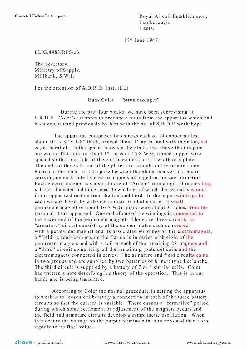
Corrected Hudson Letter - page 1 Royal Aircaft Establishment,Farnborough,Hants.
18th June 1947.
EL/G.4483/RFS/33
The Secretary,Ministry of Supply,Millbank, S.W.1.
For the attention of A.D.R.D. Inst. (EL)
Hans Coler – “Stromerzeuger”
During the past four weeks, we have been supervising at S.R.D.E. Coler ’s attempts to produce results from the apparatus which had been constructed previously by him with the aid of S.R.D.E workshops.
The apparatus comprises two stacks each of 14 copper plates, about 30” x 8” x 1/8” thick, spaced about 1” apart, and with their longest edges parallel. In the spaces between the plates and above the top pair are wound flat coils of about 12 turns of 16 S.W.G. tinned copper wire spaced so that one side of the coil occupies the full width of a plate. The ends of the coils and of the plates are brought out to terminals on boards at the ends. In the space between the plates is a vertical board carrying on each side 18 electromagnets arranged in zig-zag formation. Each electro-magnet has a solid core of “Armco” iron about 10 inches longx 1 inch diameter and three separate windings of which the second is wound in the opposite direction from the first and third. In the upper windings toeach wire is fixed, by a device similar to a lathe collet, a small permanent magnet of about 16 S.W.G. piano wire about 3 inches from the terminal at the upper end.. One end of one of the windings is connected to the lower end of the permanent magnet. There are three circuits, an “armature” circuit consisting of the copper plates each connected with a permanent magnet and its associated windings on the electromagnet, a “field” circuit comprising the flat coils in series with eight of the permanent magnets and with a coil on each of the remaining 28 magnets and a “third” circuit comprising all the remaining (outside) coils and the electromagnets connected in series. The armature and field circuits come in two groups and are supplied by two batteries of 6 inert type Leclanche. The third circuit is supplied by a battery of 7 or 8 similar cells. Coler has written a note describing his theory of the operation. This is in our hands and is being translated.
According to Coler the normal procedure in setting the apparatus to work is to loosen deliberately a connection in each of the three battery circuits so that the current is variable. There ensues a “formative” period during which some settlement or adjustment of the magnets occurs and the field and armature circuits develop a sympathetic oscillation. When this occurs the voltage on the output terminals falls to zero and then rises rapidly to its final value.
chava - public article www.chavascience.com www.chavaenergy.com
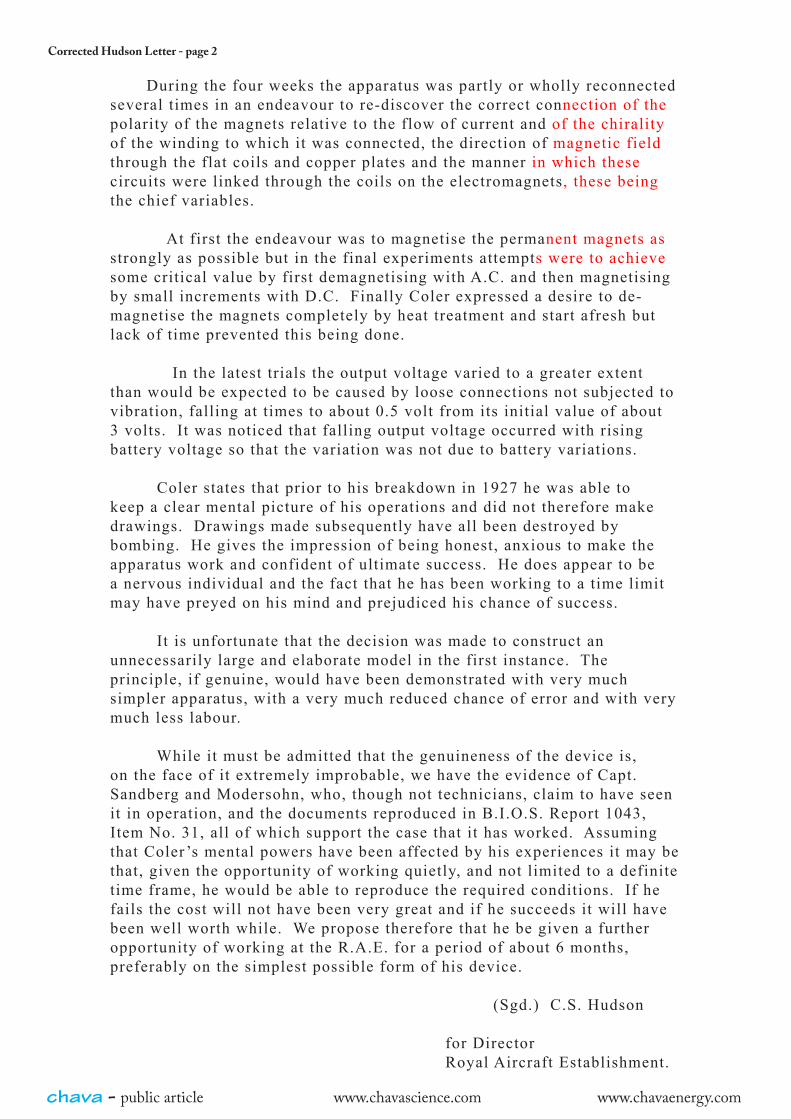
Corrected Hudson Letter - page 2
During the four weeks the apparatus was partly or wholly reconnected several times in an endeavour to re-discover the correct connection of the polarity of the magnets relative to the flow of current and of the chirality of the winding to which it was connected, the direction of magnetic field through the flat coils and copper plates and the manner in which these circuits were linked through the coils on the electromagnets, these being the chief variables.
At first the endeavour was to magnetise the permanent magnets as strongly as possible but in the final experiments attempts were to achieve some critical value by first demagnetising with A.C. and then magnetising by small increments with D.C. Finally Coler expressed a desire to de-magnetise the magnets completely by heat treatment and start afresh but lack of time prevented this being done.
In the latest trials the output voltage varied to a greater extent than would be expected to be caused by loose connections not subjected to vibration, falling at times to about 0.5 volt from its initial value of about 3 volts. It was noticed that falling output voltage occurred with rising battery voltage so that the variation was not due to battery variations.
Coler states that prior to his breakdown in 1927 he was able to keep a clear mental picture of his operations and did not therefore make drawings. Drawings made subsequently have all been destroyed by bombing. He gives the impression of being honest, anxious to make the apparatus work and confident of ultimate success. He does appear to be a nervous individual and the fact that he has been working to a time limit may have preyed on his mind and prejudiced his chance of success.
It is unfortunate that the decision was made to construct an unnecessarily large and elaborate model in the first instance. The principle, if genuine, would have been demonstrated with very much simpler apparatus, with a very much reduced chance of error and with very much less labour.
While it must be admitted that the genuineness of the device is, on the face of it extremely improbable, we have the evidence of Capt. Sandberg and Modersohn, who, though not technicians, claim to have seen it in operation, and the documents reproduced in B.I.O.S. Report 1043, Item No. 31, all of which support the case that it has worked. Assuming that Coler ’s mental powers have been affected by his experiences it may be that, given the opportunity of working quietly, and not limited to a definite time frame, he would be able to reproduce the required conditions. If he fails the cost will not have been very great and if he succeeds it will have been well worth while. We propose therefore that he be given a further opportunity of working at the R.A.E. for a period of about 6 months, preferably on the simplest possible form of his device.
(Sgd.) C.S. Hudson
for DirectorRoyal Aircraft Establishment.
chava - public article www.chavascience.com www.chavaenergy.com
Employment Record

chava - public article www.chavascience.com www.chavaenergy.com
Hickman Letter