the lesson learnt after emilia-romagna earthquakes on ...gala.gre.ac.uk/15633/7/15633...
TRANSCRIPT
1st International Conference on Natural Hazards & Infrastructure
28-30 June, 2016, Chania, Greece
The lesson learnt after Emilia-Romagna earthquakes on precast RC
structures: a case-study
M. Ercolino1 University of Greenwich, Department of Engineering Science, Central Avenue, Chatham, ME4 4TB, London,
United Kingdom
G. Magliulo, G. Manfredi University of Naples Federico II, Department of Structures for Engineering and Architecture,
Via Claudio 21, 80125 Naples, Italy
ABSTRACT
During Emilia-Romagna earthquakes (Northern Italy) on May 2012 a huge number of existing precast RC one-story
buildings was severely damaged. Most of these structures were reinforced concrete one-story buildings, hosting industrial
and commercial activities. The presented paper aims at simulating the structural behavior of an existing precast RC
building, damaged during the Emilia-Romagna earthquakes. The direct inspection showed that the most serious damage
was related to the connection systems: relative displacements between the beams and the columns; significant dislocations
between the roof elements and the beams and some cases of loss of support of the roof elements. Moreover, large rotations
were also recorded at the base of the columns. The presented study defines a reliable modeling approach and the dynamic
analyses demonstrate the capability of the proposed model in simulating the real response of the structure. The results
confirm that the most of the damage was caused by the second seismic event and the numerical evidences agree with the
real recorded damage. The numerical outcomes demonstrate the significant influence of the vertical action on the
connections behavior/failure.
Keywords: precast structures, friction connection, vertical earthquake, dynamic analysis
INTRODUCTION
On May 2012 two earthquakes hit Emilia-Romagna region and the most damaged structures were RC one-
story precast buildings. The most common precast buildings in the area are column structures: they consist of
socket footing foundations in which precast columns are placed; the columns are connected by pre-stressed
precast beams that support the roof elements. Most of the damaged precast buildings provide frictional
connections between horizontal elements (beams and roof elements) or between horizontal (beam) and vertical
(columns) members. The lack of connection devices was the main cause of damage in precast structures: the
low strength of the friction connections caused the loss of support of both roof elements from beams and beams
from columns.
The experience of a seismic event gives the possibility to develop a deeper knowledge on the seismic behavior
of a structural typology. The real response of structural and nonstructural components can be compared to the
results of numerical analyses in order to validate the modeling assumptions. Some validation of numerical
models were performed in the past for some structural typologies, as historical constructions (Milani and
Valente 2015) and masonry structures (Artioli et al. 2013). On the contrary, few similar studies were developed
for precast industrial buildings (Magliulo et al. 2008; Casotto et al. 2015). In Magliulo et al. (2008) the authors
demonstrated the vulnerability of the existing friction beam-to-column connections by means of nonlinear
1 M. Ercolino, PhD, Senior Lecturer in Civil Engineering, Department of Engineering Science, University of Greenwich,
Central Avenue, Chatham, ME4 4TB, London, United Kingdom, [email protected]
static and dynamic analyses. The adopted models of the precast RC structures did not take into account the
friction resistance of the connections: the safety was verified by comparing a posteriori the shear seismic
demand on the connections, modelled as pinned, and their friction resistance. In Casotto et al. (2015) a seismic
risk study was performed in order to define the fragility curves of Italian RC precast buildings. The collapse
limit state due to the loss of support of the beam was verified a posteriori by adopting two approaches: 1) the
shear demand in at least one column exceeding the connection capacity; 2) the sliding displacement (Newmark
sliding block analysis) of the beam exceeding its support length. It is worth noting that several experimental
studies were developed in the last decades in order to define the best models for both precast RC structural
elements and connection systems (Toniolo 2013). However, these investigations are mainly referred to new
buildings, designed for seismic actions according to modern codes. Hence, other investigations are required in
order to define reliable methods and modeling approaches for the seismic assessment of existing precast
structures.
The presented paper aims at simulating the structural collapse of a precast RC building with friction
connections, occurred during the Emilia-Romagna earthquakes in 2012. The damage was recorded during an
in–situ survey after the seismic events and both the geometrical features of the structural elements and the
mechanical properties of the materials were provided by the original technical reports. The main goal of the
paper is the definition of a reliable modeling approach, validated on the actual recorded damage of the structure
after the earthquakes. The comparison between the analytical results and the actual response of the investigated
structure leads to some considerations about the main causes of the recorded response.
THE CASE-STUDY
The investigated case study is a precast building located in Mirandola (Modena, Italy), designed and built in
1990. It has the typical features of column structures: it consists of an assemblage of precast RC columns, fixed
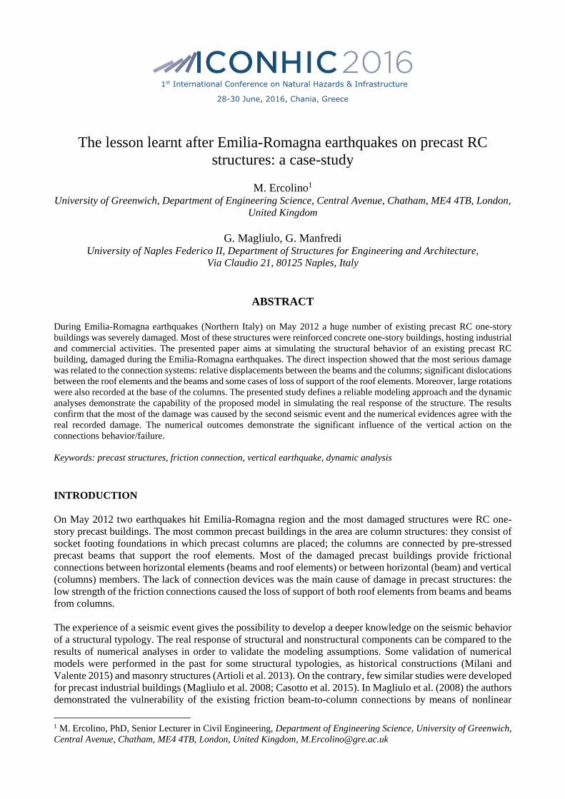
at the base with isolated socket foundations. Fig.1 shows the plan view of the structure. The total height of the
columns is equal to 7.3 m and the structure has 8.9m high vertical panels along the perimeter. The total seismic
weight of the structure is equal to about 3.0 kN/m2.
Figure 1. Plan view of the case study
Structural elements and connection systems
In the X direction, the columns are connected at the top by precast beams (principal beams). The principal
beams are prestressed elements with a cross-section that varies along its longitudinal axis (global X-axis) in
terms of both height and cross-section shape. The beam has a rectangular shaped cross-section at the
connection with the column and an I-shaped cross-section at the mid-span. In the Y direction, the columns are
connected by U cross-section girders (secondary beams) with a base of 60cm and a total height of 40cm. The
roof consists of TT precast elements, supported by the principal beams and spaced out by transparent plastic
elements.
Four different typologies of columns are identified in the structure by taking into account the cross-section
dimensions, the longitudinal reinforcement and the applied axial force (see the labels in Figure 1). According
20m 20m 20m 20m 20m 20m
50
m
10
m1
0m
10
m1
0m
10
m
D
X
YB B B B B D
C
C
C
C
C
C
C
C
A A A A A
A A A A A
A A A A A
A A A A A
B B B B B
N
D D
120m

to the values of the axial load, the columns are distinguished in internal columns (columns A), perimetric
columns (columns B and C) and corner columns (columns D). According to the cross-section shapes and the
longitudinal reinforcement, two cross-sections of the columns can be distinguished in the structure:
1. rectangular shaped columns (40cmx50cm), reinforced with four 16mm diameter bars and four 18mm
diameter bars (ρ=0.91%) in Figure 2(a);
2. square-shaped columns (50cmx50cm), reinforced with four 16mm diameter bars and four 18mm
diameter bars (ρ=0.73%) in Figure 2(b).
All the rectangular columns are placed with the long side along the X direction. In both rectangular and square
shaped columns, the transversal reinforcement consists of 6mm diameter stirrups spaced of 20cm along the
height.
For all the structural elements, the adopted concrete has a characteristic cubic compressive strength of 50MPa.
The columns are precast elements and the reinforcement steel has a characteristic yielding strength of 440MPa.
In this paper, the reinforcement details of both beams and roof elements are not reported since these elements
can be modelled as elastic elements in the structural model, as described in the following section.
(a)
(b)
Figure 2. Cross-sections and reinforcement details of columns: (a) A and C columns; (b) B and D columns
The investigated structure has the typical features of an Italian twenty-century one-story precast RC structure,
not designed for seismic actions. The connections between the structural elements (beams, columns and roof
elements) are friction connections, i.e. relying only on the friction between the connected elements, without
any mechanical device. The connections between the principal beams and the columns provide only a neoprene
pad between the two concrete elements and the contact surface has a length of 23cm in the X direction. Friction
connections are also provided between the roof elements and the principal beams with a neoprene pad and a
contact surface length of 13cm in the Y direction. The connection between the girder and the column provides
bolted steel angles with a very low rotational strength.
Recorded damage
The investigated building experienced serious damages during the second seismic event on May 29th.
Precast columns experienced significant rotations at the base: large cracking and spalling of the
concrete demonstrated the attainment of the yielding strength of the elements (Figure 3). The columns
damage caused an evident rotation of the structure along the X direction (Figure 4 4).
The principal beams experienced small relative displacements with respect to the supporting columns
(Figure 5(a)). The amplitude of the experienced displacements did not exceed the contact surface of
the beams (23cm): no loss of support phenomena of principal beam occurred in the structure after the
two seismic events.
The roof elements experienced larger relative displacements with respect to the supporting principal
beams and some elements collapsed because of the loss of the support phenomenon (Figure 5(b)).

Figure 3. Damage at the column base after the
event on May 29th
Figure 4. Rotation of the columns along the X
direction after the event on May 29th
(a) (b)
Figure 5. Damage of the connection systems after the event on May 29th: (a) relative displacement between
beam and column and (b) loss of support of the roof elements
METHODOLOGY
Nonlinear dynamic analyses are performed by the OpenSees program (McKenna and Fenves 2013), with the
accelerograms of the two seismic events. The acceleration-time histories were recorded by the station MRN
(Mirandola, Modena, Italy) of the Italian National Accelerometric Network during the two main events on
May 2012. The adopted station is very close to the building site. The considered station is placed on a flat “C”
class soil (shear wave velocity ranging from 180m/s to 360m/s) according to Eurocode 8 (CEN 2005), as
reported in the Italian Accelerometric Archive (Luzi et al. 2008).
The nonlinear model provides all the structural elements, according to their real dimensions and location; all
the masses are distributed along the structural elements.
The dissipative behavior of the structure is concentrated at the base of the precast columns, whereas all the
horizontal structural elements (beams, girders and roof elements) are introduced in the model as elastic
elements. A lumped plasticity approach is assumed in order to simulate the inelastic response of the columns.
The moment-rotation envelope of the columns hinges consists of three characteristic points: the cracking, the
yielding and the ultimate point. The cracking point (moment and rotation) is defined based on the gross section
properties. A fiber analysis of the cross-section provides the yielding moment value, whereas the ultimate
moment is defined by considering a very low hardening (1%) value, assumed only for numerical purposes.
The yielding and ultimate rotations are evaluated according to Fardis and Biskinis (2003) .The hysteretic rule
follows the indications given in Ibarra et al. (2005). Fig.6-Fig.8 show the moment-rotation curves for the
columns in the case-study around the two horizontal directions.

(a) (b)
Figure 6. Moment-rotation envelopes of the column A around (a) the X direction and (b) the Y direction
(a) (b)
Figure 7. Moment-rotation envelopes of the column C around (a) the X direction and (b) the Y direction
(a) (b)
Figure 8. Moment-rotation envelopes of (a) the column B and of (b) the column D
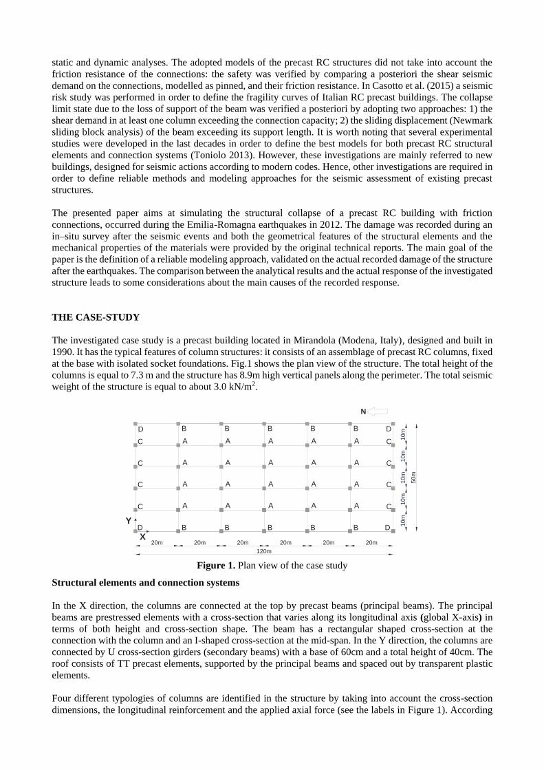
Fig.9 and Fig.10 show the layout of the elements and the considered eccentricities for all the connection
systems. The connections are defined by “equal DOF” constraints between the two linked elements. With
regards to the beam-to-column connection (blue circles in Figure 9), the translational degree of freedom along
the X direction is not constrained: in this direction a model of the friction connection is implemented. Similarly,
the translational degree of freedom along the Y direction is not fixed for the roof-to-beam connections (red
circles in Figure 9 and in Figure 10). Moreover, in both these two connections, the translational degree of
freedom along the Z direction is not constrained, in order to evaluate the influence of the vertical components
of the earthquakes. The frictional connections between the structural elements are introduced in the nonlinear
model by means of the “Flat slider bearing” element of the OpenSees library. A Coulomb model is assumed
for the frictional behavior and the initial elastic stiffness is defined as the shear stiffness of the neoprene pad
(G=2.7MPa). In the vertical direction (Z direction), the neoprene compressive stiffness is assigned, while a
free displacement is allowed in the opposite direction, in order to capture the element uplift. The compressive
stiffness is evaluated by assuming Young’s modulus equal to 6MPa. The friction coefficient () are evaluated
according to Magliulo et al. (2011). The beam-to-column connections have a friction coefficient equal to 0.12
and 0.14 for the largest and the lowest axial force, respectively. The roof-to-beam connections have a friction
coefficient equal to 0.12 in the case of the big roof elements and 0.13 for the small ones.
0 0.02 0.04 0.06 0.08 0.10
50
100
150
200
250
300
350
400
x [-]
Mx [
kN
m]
0 0.02 0.04 0.06 0.08 0.10
50
100
150
200
250
300
350
400
y [-]
My [
kN
m]
0 0.02 0.04 0.06 0.08 0.10
50
100
150
200
250
300
350
400
x [-]
Mx [
kN
m]
0 0.02 0.04 0.06 0.08 0.10
50
100
150
200
250
300
350
400
y [-]
My [
kN
m]
0 0.02 0.04 0.06 0.08 0.10
50
100
150
200
250
300
350
400
[-]
M [
kN
m]
Around X
Around Y
0 0.02 0.04 0.06 0.08 0.10
50
100
150
200
250
300
350
400
[-]
M [
kN
m]
Around X
Around Y
Concerning the connection between the secondary beams (girders) and the columns (black circle in Figure 9),
a hinge is assumed, according to the features of the connection system. Therefore, the girder-to-column
connections are able to avoid the relative displacements between the two connected elements in the Y direction.
Figure 9. Structural elements layout and connections
position in the X direction
Figure 10. Structural elements layout and
connections position in the Y direction
RESULTS AND DISCUSSION
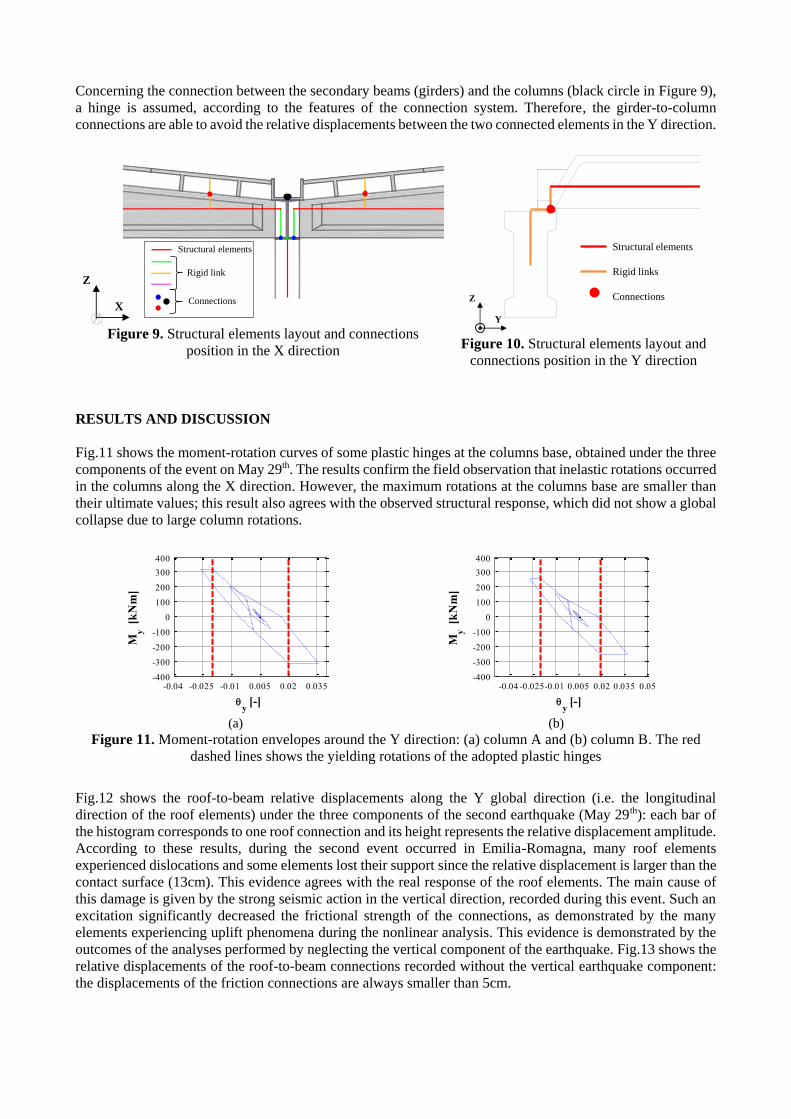
Fig.11 shows the moment-rotation curves of some plastic hinges at the columns base, obtained under the three
components of the event on May 29th. The results confirm the field observation that inelastic rotations occurred
in the columns along the X direction. However, the maximum rotations at the columns base are smaller than
their ultimate values; this result also agrees with the observed structural response, which did not show a global
collapse due to large column rotations.
(a) (b)
Figure 11. Moment-rotation envelopes around the Y direction: (a) column A and (b) column B. The red
dashed lines shows the yielding rotations of the adopted plastic hinges
Fig.12 shows the roof-to-beam relative displacements along the Y global direction (i.e. the longitudinal
direction of the roof elements) under the three components of the second earthquake (May 29th): each bar of
the histogram corresponds to one roof connection and its height represents the relative displacement amplitude.
According to these results, during the second event occurred in Emilia-Romagna, many roof elements
experienced dislocations and some elements lost their support since the relative displacement is larger than the
contact surface (13cm). This evidence agrees with the real response of the roof elements. The main cause of
this damage is given by the strong seismic action in the vertical direction, recorded during this event. Such an
excitation significantly decreased the frictional strength of the connections, as demonstrated by the many
elements experiencing uplift phenomena during the nonlinear analysis. This evidence is demonstrated by the
outcomes of the analyses performed by neglecting the vertical component of the earthquake. Fig.13 shows the
relative displacements of the roof-to-beam connections recorded without the vertical earthquake component:
the displacements of the friction connections are always smaller than 5cm.
Structural elements
Rigid link
Connections
Z
X
Structural elements
Rigid links
ConnectionsZ
Y
-0.04 -0.025 -0.01 0.005 0.02 0.035-400
-300
-200
-100
0
100
200
300
400
y [-]
My
[kN
m]
-0.04 -0.025-0.01 0.005 0.02 0.035 0.05-400
-300
-200
-100
0
100
200
300
400
y [-]
My
[kN
m]
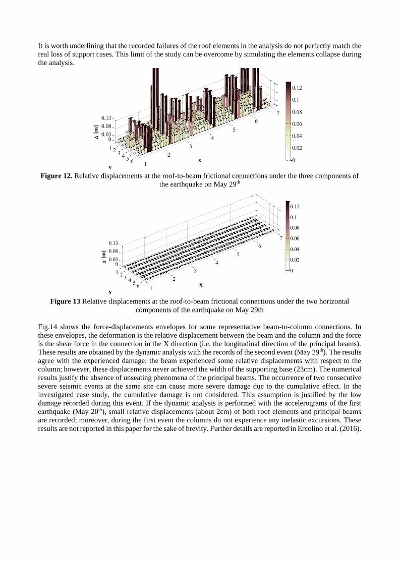
It is worth underlining that the recorded failures of the roof elements in the analysis do not perfectly match the
real loss of support cases. This limit of the study can be overcome by simulating the elements collapse during
the analysis.
Figure 12. Relative displacements at the roof-to-beam frictional connections under the three components of
the earthquake on May 29th
Figure 13 Relative displacements at the roof-to-beam frictional connections under the two horizontal
components of the earthquake on May 29th
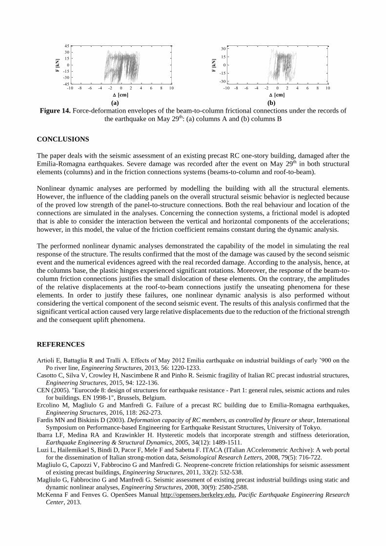
Fig.14 shows the force-displacements envelopes for some representative beam-to-column connections. In
these envelopes, the deformation is the relative displacement between the beam and the column and the force
is the shear force in the connection in the X direction (i.e. the longitudinal direction of the principal beams).
These results are obtained by the dynamic analysis with the records of the second event (May 29th). The results
agree with the experienced damage: the beam experienced some relative displacements with respect to the
column; however, these displacements never achieved the width of the supporting base (23cm). The numerical
results justify the absence of unseating phenomena of the principal beams. The occurrence of two consecutive
severe seismic events at the same site can cause more severe damage due to the cumulative effect. In the
investigated case study, the cumulative damage is not considered. This assumption is justified by the low
damage recorded during this event. If the dynamic analysis is performed with the accelerograms of the first
earthquake (May 20th), small relative displacements (about 2cm) of both roof elements and principal beams
are recorded; moreover, during the first event the columns do not experience any inelastic excursions. These
results are not reported in this paper for the sake of brevity. Further details are reported in Ercolino et al. (2016).
1
2
3
4
5
6
7
12
34
56
00.03
0.08
0.13
Bayx
Bayy
[
m]
0
0.02
0.04
0.06
0.08
0.1
0.12
Y
X
1
2
3
4
5
6
7
12
34
56
00.03
0.08
0.13
Bayx
Bayy
[
m]
0
0.02
0.04
0.06
0.08
0.1
0.12
Y
X
(a) (b)
Figure 14. Force-deformation envelopes of the beam-to-column frictional connections under the records of
the earthquake on May 29th: (a) columns A and (b) columns B
CONCLUSIONS
The paper deals with the seismic assessment of an existing precast RC one-story building, damaged after the
Emilia-Romagna earthquakes. Severe damage was recorded after the event on May 29th in both structural
elements (columns) and in the friction connections systems (beams-to-column and roof-to-beam).
Nonlinear dynamic analyses are performed by modelling the building with all the structural elements.
However, the influence of the cladding panels on the overall structural seismic behavior is neglected because
of the proved low strength of the panel-to-structure connections. Both the real behaviour and location of the
connections are simulated in the analyses. Concerning the connection systems, a frictional model is adopted
that is able to consider the interaction between the vertical and horizontal components of the accelerations;
however, in this model, the value of the friction coefficient remains constant during the dynamic analysis.
The performed nonlinear dynamic analyses demonstrated the capability of the model in simulating the real
response of the structure. The results confirmed that the most of the damage was caused by the second seismic
event and the numerical evidences agreed with the real recorded damage. According to the analysis, hence, at
the columns base, the plastic hinges experienced significant rotations. Moreover, the response of the beam-to-
column friction connections justifies the small dislocation of these elements. On the contrary, the amplitudes
of the relative displacements at the roof-to-beam connections justify the unseating phenomena for these
elements. In order to justify these failures, one nonlinear dynamic analysis is also performed without
considering the vertical component of the second seismic event. The results of this analysis confirmed that the
significant vertical action caused very large relative displacements due to the reduction of the frictional strength
and the consequent uplift phenomena.
REFERENCES
Artioli E, Battaglia R and Tralli A. Effects of May 2012 Emilia earthquake on industrial buildings of early ’900 on the
Po river line, Engineering Structures, 2013, 56: 1220-1233.
Casotto C, Silva V, Crowley H, Nascimbene R and Pinho R. Seismic fragility of Italian RC precast industrial structures,
Engineering Structures, 2015, 94: 122-136.
CEN (2005). "Eurocode 8: design of structures for earthquake resistance - Part 1: general rules, seismic actions and rules
for buildings. EN 1998-1", Brussels, Belgium.
Ercolino M, Magliulo G and Manfredi G. Failure of a precast RC building due to Emilia-Romagna earthquakes,
Engineering Structures, 2016, 118: 262-273.
Fardis MN and Biskinis D (2003). Deformation capacity of RC members, as controlled by flexure or shear, International
Symposium on Performance-based Engineering for Earthquake Resistant Structures, University of Tokyo.
Ibarra LF, Medina RA and Krawinkler H. Hysteretic models that incorporate strength and stiffness deterioration,
Earthquake Engineering & Structural Dynamics, 2005, 34(12): 1489-1511.
Luzi L, Hailemikael S, Bindi D, Pacor F, Mele F and Sabetta F. ITACA (ITalian ACcelerometric Archive): A web portal
for the dissemination of Italian strong-motion data, Seismological Research Letters, 2008, 79(5): 716-722.
Magliulo G, Capozzi V, Fabbrocino G and Manfredi G. Neoprene-concrete friction relationships for seismic assessment
of existing precast buildings, Engineering Structures, 2011, 33(2): 532-538.
Magliulo G, Fabbrocino G and Manfredi G. Seismic assessment of existing precast industrial buildings using static and
dynamic nonlinear analyses, Engineering Structures, 2008, 30(9): 2580-2588.
McKenna F and Fenves G. OpenSees Manual http://opensees.berkeley.edu, Pacific Earthquake Engineering Research
Center, 2013.
-10 -8 -6 -4 -2 0 2 4 6 8 10-45
-30
-15
0
15
30
45
[cm]
F [
kN
]
-10 -8 -6 -4 -2 0 2 4 6 8 10
-30
-15
0
15
30
[cm]
F [
kN
]

Milani G and Valente M. Comparative pushover and limit analyses on seven masonry churches damaged by the 2012
Emilia-Romagna (Italy) seismic events: Possibilities of non-linear finite elements compared with pre-assigned failure
mechanisms, Engineering Failure Analysis, 2015, 47, Part A: 129-161.
Toniolo G. Safecast Project: European Research on Seismic Behaviour of the Connections of Precast Structures,
COMPDYN 2013 4th ECCOMAS Thematic Conference on Computational Methods in Structural Dynamics and
Earthquake Engineering, Kos Island, Greece, 12–14 June 2013, 2013.