the magazine of twi cutting-edge technology for nuclear ... · pdf filetwi events september...
TRANSCRIPT
TWI Events
September 2013
WorkshopCold and Thermal Spray Technology UpdateThu 19 Great Abington
SeminarRailway Asset ManagementFri 20 Great Abington
October 2013
Technical Group MeetingStructural Integrity: Probabilistic Aspects of Structural Integrity Defect AssessmentWed 9 Rotherham
Technical Group MeetingWelding Processes: Recent Advancement in Welding Processes and Weld MonitoringTue 29Rotherham
Collaborative Open DayThu 31Rotherham
November 2013
Technical Group MeetingPressure and Process PlantThu 7Middlesbrough
Issue 185 July/August 2013
T h e m a g a z i n e o f T W I
w w w . t w i . c o . u k e - m a i l : t w i @ t w i . c o . u k
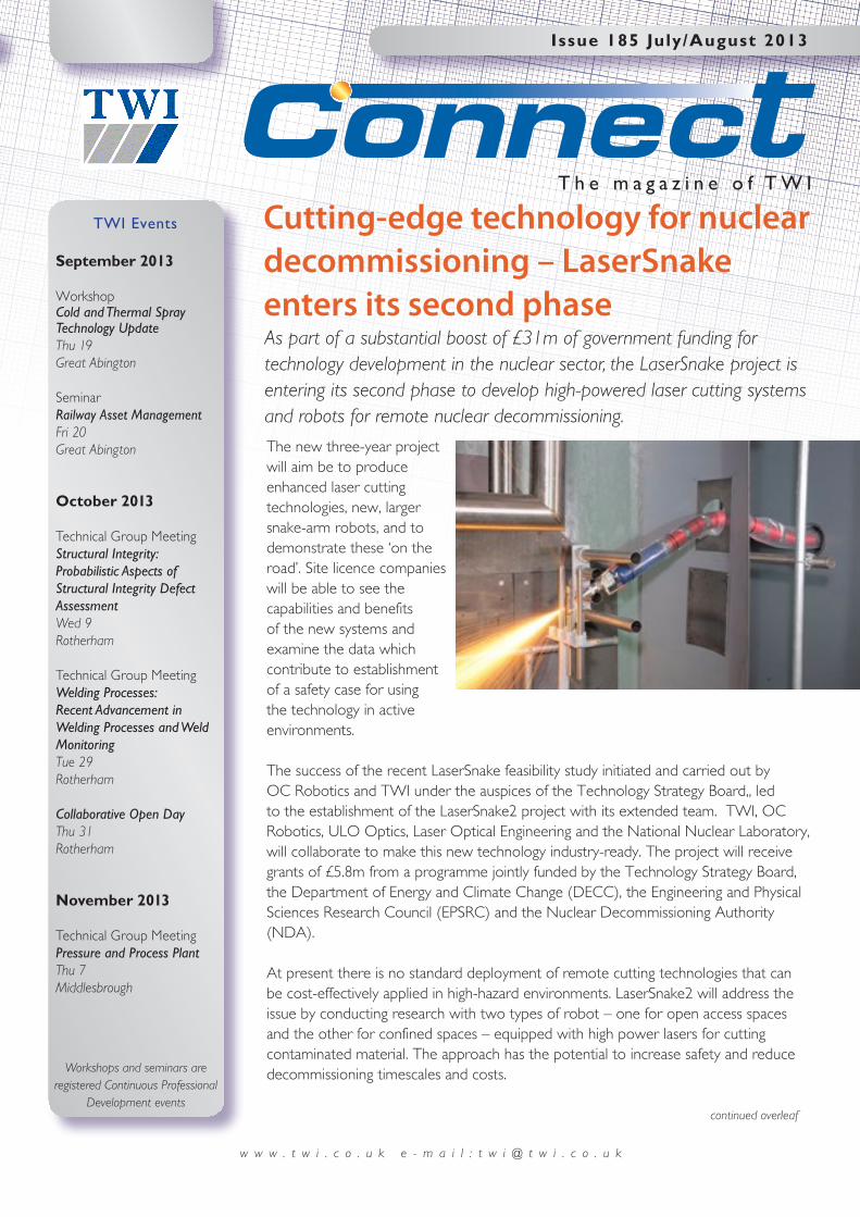
Cutting-edge technology for nuclear decommissioning – LaserSnake enters its second phase
The new three-year project will aim be to produce enhanced laser cutting technologies, new, larger snake-arm robots, and to demonstrate these ‘on the road’. Site licence companies will be able to see the capabilities and benefits of the new systems and examine the data which contribute to establishment of a safety case for using the technology in active environments.
The success of the recent LaserSnake feasibility study initiated and carried out by OC Robotics and TWI under the auspices of the Technology Strategy Board,, led to the establishment of the LaserSnake2 project with its extended team. TWI, OC Robotics, ULO Optics, Laser Optical Engineering and the National Nuclear Laboratory, will collaborate to make this new technology industry-ready. The project will receive grants of £5.8m from a programme jointly funded by the Technology Strategy Board, the Department of Energy and Climate Change (DECC), the Engineering and Physical Sciences Research Council (EPSRC) and the Nuclear Decommissioning Authority (NDA).
At present there is no standard deployment of remote cutting technologies that can be cost-effectively applied in high-hazard environments. LaserSnake2 will address the issue by conducting research with two types of robot – one for open access spaces and the other for confined spaces – equipped with high power lasers for cutting contaminated material. The approach has the potential to increase safety and reduce decommissioning timescales and costs.
As part of a substantial boost of £31m of government funding for technology development in the nuclear sector, the LaserSnake project is entering its second phase to develop high-powered laser cutting systems and robots for remote nuclear decommissioning.
Workshops and seminars are registered Continuous Professional
Development eventscontinued overleaf
2
July/August 2013
Connect Ju l y /August 2013 w w w . t w i . c o . u k e - m a i l : t w i @ t w i . c o . u k
Chemineer LtdUKDesign, manufacture and sales of mixing and agitation equipment and systems
Contraves Advanced Devices Sdn BhdMalaysiaElectronics manufacture
DSTO (Australian Government)AustraliaScientific support and R&D for Australian defence
Fairlead MaritimeUKMaritime consultancy
GE Oil & GasUSAOn- and offshore oil and gas drilling and production
Georg Fischer Piping SystemsSwitzerlandPlastic piping systems
Hyundai Rotem CoRepublic of KoreaRailway systems, defence systems, plant and machinery
Interserve Industrial Services Ltd - Mechanical DivisionUKMechanical fabrication, pipework and pressure vessels
Johnson Contols Inc – Power SolutionsUSAProducer of lead acid batteries
Otis Ltd Pan Tfl DepartmentUKEscalator engineering
Pelamis Wave Power LtdUKOffshore wave power
Perenco UK LtdUKOil and gas exploration and production Rusayl Institute LLCOmanEngineering training for the Gulf region
Serious Engineering LtdUKPrecision engineering and metal fabrication
New Members of TWITWI is pleased to welcome the following as Industrial Members
We are always open to applications from Materials Scientists, Metallurgists and Welding Engineers,
in particular experts in corrosion and ferritic steels with knowledge of the oil and gas sector. For current vacancies, please see our careers page www.twi.co.uk/careers
or to apply speculatively email your CV and covering letter to [email protected]
The objectives of LaserSnake2 are to:
• develop long-reach, snake-arm robots for hazardous and confined spaces, in air and underwater;
• develop laser cutting optics for safe, remote cutting in air and water – focusing on nuclear decommissioning;
• consider the regulatory and certification issues associated with tele-operated delivery of laser cutting solutions for the nuclear industry;
• combine snake-arms and mobile robots to create a mobile platform for exploration of complex spaces.
The demonstration phase for LaserSnake2 will be presented on behalf of all the project partners in 2015 at TWI near Cambridge then ‘on the road’ at a number of nuclear sites.
For more information about the use of laser techniques for nuclear decommissioning contact [email protected].
Q
Aregister now www.twi.co.uk
Are there any NDT methods for electrofusion joints?
How can I avoid local brittle zones (LBZs)?
Is laser welding used in the manufacture of aluminium alloy airframe structures?
w w w . t w i . c o . u k e - m a i l : t w i @ t w i . c o . u k Connect Ju l y /August 2013
July/August 2013
3
CreepImage: Inspecting creep damage in critical power plant componentsThe increasing demand for low cost energy is forcing many power stations to run well beyond their original design life. The safe extension of a power station’s operating life requires new inspection techniques which must accurately detect creep damage and predict the remaining life of a component.
CreepImage, a project run by European companies (Aimen, Dantec Dynamics, IKnowHow, Integrity NDT, Pro Optica and TWI) and funded by the Research Executive Agency (REA) of the European Commission is developing an optical inspection technique for long-term measurement and monitoring of creep deformation in engineering structures. The inspection process is particularly suited to the harsh operating conditions of a power station, where high temperatures and radiation often prevent the use of conventional inspection methods.
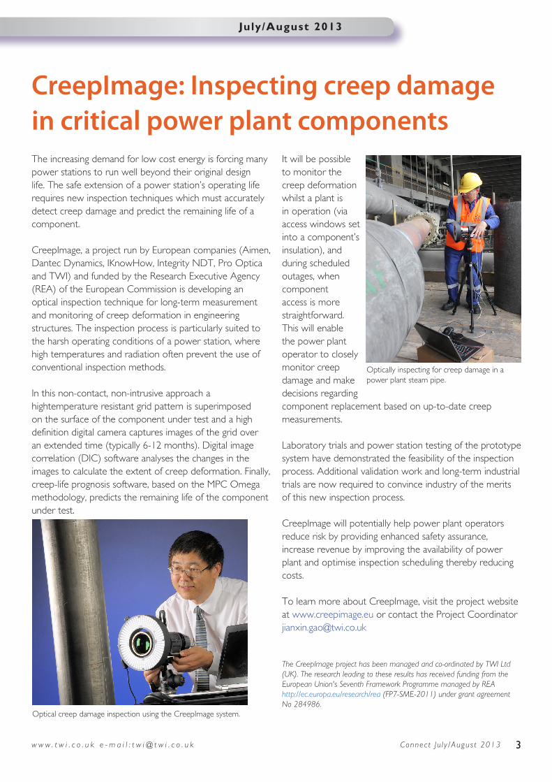
In this non-contact, non-intrusive approach a hightemperature resistant grid pattern is superimposed on the surface of the component under test and a high definition digital camera captures images of the grid over an extended time (typically 6-12 months). Digital image correlation (DIC) software analyses the changes in the images to calculate the extent of creep deformation. Finally, creep-life prognosis software, based on the MPC Omega methodology, predicts the remaining life of the component under test.
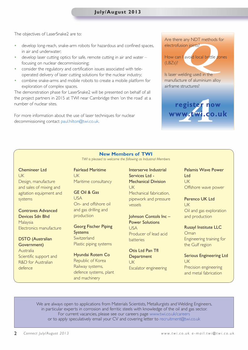
It will be possible to monitor the creep deformation whilst a plant is in operation (via access windows set into a component’s insulation), and during scheduled outages, when component access is more straightforward. This will enable the power plant operator to closely monitor creep damage and make decisions regarding component replacement based on up-to-date creep measurements.
Laboratory trials and power station testing of the prototype system have demonstrated the feasibility of the inspection process. Additional validation work and long-term industrial trials are now required to convince industry of the merits of this new inspection process.
CreepImage will potentially help power plant operators reduce risk by providing enhanced safety assurance, increase revenue by improving the availability of power plant and optimise inspection scheduling thereby reducing costs.
To learn more about CreepImage, visit the project website at www.creepimage.eu or contact the Project Coordinator [email protected]
The CreepImage project has been managed and co-ordinated by TWI Ltd (UK). The research leading to these results has received funding from the European Union's Seventh Framework Programme managed by REA http://ec.europa.eu/research/rea (FP7-SME-2011) under grant agreement No 284986.
Optical creep damage inspection using the CreepImage system.
Optically inspecting for creep damage in a power plant steam pipe.
Connect Ju l y /August 2013 w w w . t w i . c o . u k e - m a i l : t w i @ t w i . c o . u k4
Technology Transfer
Job Knowledge
125 Radiography Part 2
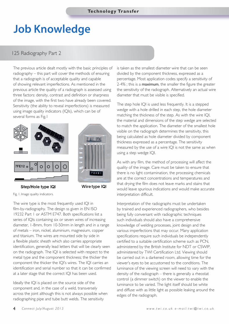
The previous article dealt mostly with the basic principles of radiography – this part will cover the methods of ensuring that a radiograph is of acceptable quality and capable of showing relevant imperfections. As mentioned in the previous article the quality of a radiograph is assessed using three factors: density, contrast and definition or sharpness of the image, with the first two have already been covered. Sensitivity (the ability to reveal imperfections) is measured using image quality indicators (IQIs), which can be of several forms as Fig.1
The wire type is the most frequently used IQI in film-by-radiography. The design ss given in EN ISO 19232 Part 1 or ASTM E747. Both specifications list a series of IQIs containing six or seven wires of increasing diameter, 1-8mm, from 10-50mm in length and in a range of metals – iron, nickel, aluminium, magnesium, copper and titanium. The wires are mounted side by side in a flexible plastic sheath which also carries appropriate identification, generally lead letters that will be clearly seen on the radiograph. The IQI is selected with respect to the metal type and the component thickness; the thicker the component the thicker the IQI’s wires. The IQI carries an identification and serial number so that it can be confirmed at a later stage that the correct IQI has been used.
Ideally the IQI is placed on the source side of the component and, in the case of a weld, transversely across the joint although this is not always possible when radiographing pipe and tube butt welds. The sensitivity
is taken as the smallest diameter wire that can be seen divided by the component thickness, expressed as a percentage. Most application codes specify a sensitivity of 2-4% ; this is a maximum, the smaller the figure the greater the sensitivity of the radiograph. Alternatively an actual wire diameter that must be visible is specified.
The step hole IQI is used less frequently. It is a stepped wedge with a hole drilled in each step, the hole diameter matching the thickness of the step. As with the wire IQI, the material and dimensions of the step wedge are selected to match the application. The diameter of the smallest hole visible on the radiograph determines the sensitivity, this being calculated as hole diameter divided by component thickness expressed as a percentage. The sensitivity measured by the use of a wire IQI is not the same as when using a step wedge IQI.
As with any film, the method of processing will affect the quality of the image. Care must be taken to ensure that there is no light contamination, the processing chemicals are at the correct concentrations and temperatures and that drying the film does not leave marks and stains that would leave spurious indications and would make accurate interpretation difficult.
Interpretation of the radiographs must be undertaken by trained and experienced radiographers, who besides being fully conversant with radiographic techniques such individuals should also have a comprehensive knowledge of welding processes, joint design and the various imperfections that may occur. Many application specifications require such individuals be independently certified to a suitable certification scheme such as PCN, administered by the British Institute for NDT or CSWIP, administered by TWI Certification Ltd. Viewing should be carried out in a darkened room, allowing time for the viewer’s eyes to be accustomed to the conditions. The luminance of the viewing screen will need to vary with the density of the radiograph – there is generally a rheostat control (a dimmer switch) on the viewer to enable the luminance to be varied. The light itself should be white and diffuse with as little light as possible leaking around the edges of the radiograph.
Fig. 1. Image quality indicators.

w w w . t w i . c o . u k e - m a i l : t w i @ t w i . c o . u k Connect Ju l y /August 2013
Technology Transfer
5
Radiography of flat plates and cylinders large enough to permit entry for placement of the film is a relatively simple operation, as shown in Fig. 1 of the previous article. Lead numbers are placed at fixed intervals along the plate adjacent to the weld or around the circumference of a pipe to enable the position of any imperfections to be accurately located. The weld also carries a unique identification number reproduced on the radiograph by the use of lead figures placed adjacent to the weld.
Radiography of pipes, where access to the bore to place the film is not possible presents problems and terms such as SWSI and DWSI are used as shorthand to identify the various techniques that may be used.
In single wall, single image (SWSI) the radiographic source is placed inside the pipe by some suitable method, the film wrapped around the outside and the exposure made as shown in Fig. 2, also known as a panoramic exposure. The IQI is placed on the outside of the pipe immediately beneath the film. Both X- and gamma-radiography can be used with the source placed in position by use of a pre-placed spider or a crawler unit. This method is most commonly used for the inspection of pipelines where the weld can be radiographed in one exposure, making the technique rapid and cost effective.
Where access to the bore is not possible or the pipe diameter too small to permit the use of an internal source then the double wall, single image (DWSI) technique is used. The film is placed on the outside of the pipe on the farthest side from the radiographic source, as shown in Fig. 3. The source may be offset slightly to avoid an image of the upper part of the weld projected onto the film or directly in line. The source may be close or a substantial distance from the pipe, the location being a compromise between a less sharp image but short exposure time for a small stand-off and sharper image but longer exposure time for a large stand-off. The need to penetrate two wall
thicknesses means that the sensitivity will be poorer than with the SWSI technique. The technique also requires multiple exposures to enable the complete circumference of the pipe to be examined – specification or contract requirements frequently specify the minimum number of exposures to ensure complete coverage and images of an acceptable quality. The technique is generally used on pipes over 80mm in diameter.
The last technique is double wall, double image (DWDI), generally used only on pipes under 75-80mm in diameter. By offsetting the source from the weld centre line and using a long source to film distance it is possible to project an image onto the film of both the upper and the lower parts of the weld as shown in Fig. 4. As with the DWSI technique multiple exposures are required to achieve complete coverage.
Part 3 will look at some of the more sophisticated radiographic techniques and the advantages and disadvantages of radiography.
Fig. 2 Single wall, single image or panoramic radiographic technique.
Fig. 3 Double wall, single image
Fig.4. Double wall double image radiograph of a pipe butt weld. Note the IQI, identification numbers and position markers.
This article was written by Gene Mathers.
Connect Ju l y /August 2013 w w w . t w i . c o . u k e - m a i l : t w i @ t w i . c o . u k6
July/August 2013
Working alongside Industrial Member company Subsea Riser Products (SRP), TWI has demonstrated its capabilities with the development of a bespoke test programme to qualify a new position mooring system for offshore vessels (the Rocksteady connector). The connector design includes pre-tensioned fingers which enhance its fatigue resistance.
Initially, the TWI project team produced test-specific risk assessments and agreed a test procedure.
The qualification requirements for the new connector were demanding and included applying static tensile loads of 9900kN (1010 tonnes), fatigue loading at three different load
levels and a test involving disconnecting the connector while under a tensile load. SRP also wished to measure the strain experienced by the fingers in the connector during the application of the pre-load, and during the external load tests.
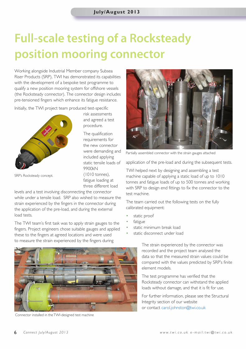
The TWI team’s first task was to apply strain gauges to the fingers. Project engineers chose suitable gauges and applied these to the fingers at agreed locations and were used to measure the strain experienced by the fingers during
application of the pre-load and during the subsequent tests.
TWI helped next by designing and assembling a test machine capable of applying a static load of up to 1010 tonnes and fatigue loads of up to 500 tonnes and working with SRP to design end fittings to fix the connector to the test machine.
The team carried out the following tests on the fully calibrated equipment:
• static proof• fatigue• static minimum break load• static disconnect under load
The strain experienced by the connector was recorded and the project team analysed the data so that the measured strain values could be compared with the values predicted by SRP’s finite element models.
The test programme has verified that the Rocksteady connector can withstand the applied loads without damage, and that it is fit for use.
For further information, please see the Structural Integrity section of our website or contact [email protected]
Full-scale testing of a Rocksteady position mooring connector
Partially assembled connector with the strain gauges attached
Connector installed in the TWI-designed test machine
SRP’s Rocksteady concept.
7w w w . t w i . c o . u k e - m a i l : t w i @ t w i . c o . u k Connect Ju l y /August 2013
July/August 2013
News in brief
For further information on TWI visit the website at www.twi.co.uk
Aerospace Industry Panel Meeting
The 40th Aerospace Industry Panel meeting will take place at TWI on Wednesday 18 September 2013 with presentations from RTI on SPFDB of Ti components and from TWI on sprayed coatings, brazing and diffusion bonding, microwave processing of composites, modelling of keyhole welding and the design and optimisation of a composite component. For more details contact [email protected].
Cold Spray Technology Event
A cold spray and thermal spray technology event will take place at TWI during the morning of Thursday 19 September 2013, followed in the afternoon by the launch of a Group Sponsored Project on Improved Surface Treatment and Structural Repair of Magnesium Alloy Components using Cold Spray in the afternoon. For more details please contact [email protected]
Railway Asset Management
TWI is hosting a seminar on Railway Asset Management on Friday 20 September 2013, to focus on key technical areas, share relevant case studies and encourage further collaboration in this area. For more details please contact [email protected].
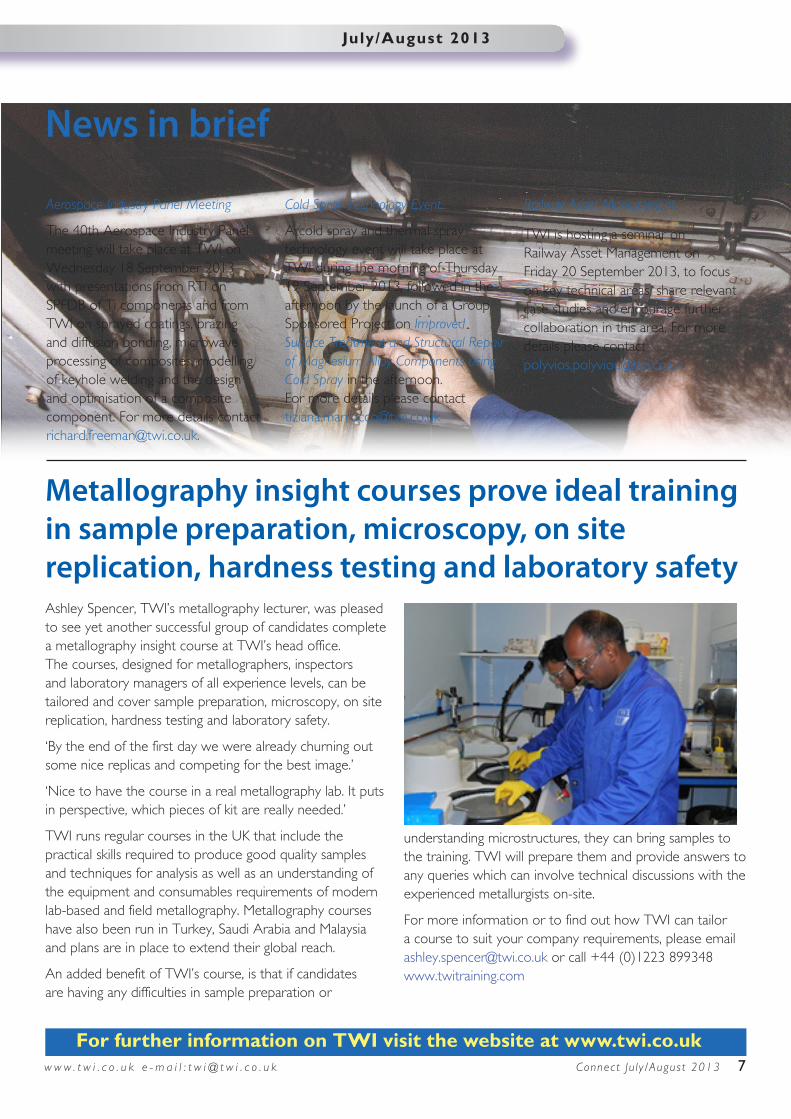
Ashley Spencer, TWI’s metallography lecturer, was pleased to see yet another successful group of candidates complete a metallography insight course at TWI’s head office. The courses, designed for metallographers, inspectors and laboratory managers of all experience levels, can be tailored and cover sample preparation, microscopy, on site replication, hardness testing and laboratory safety.
‘By the end of the first day we were already churning out some nice replicas and competing for the best image.’
‘Nice to have the course in a real metallography lab. It puts in perspective, which pieces of kit are really needed.’
TWI runs regular courses in the UK that include the practical skills required to produce good quality samples and techniques for analysis as well as an understanding of the equipment and consumables requirements of modern lab-based and field metallography. Metallography courses have also been run in Turkey, Saudi Arabia and Malaysia and plans are in place to extend their global reach.
An added benefit of TWI’s course, is that if candidates are having any difficulties in sample preparation or
understanding microstructures, they can bring samples to the training. TWI will prepare them and provide answers to any queries which can involve technical discussions with the experienced metallurgists on-site.
For more information or to find out how TWI can tailor a course to suit your company requirements, please email [email protected] or call +44 (0)1223 899348 www.twitraining.com
Metallography insight courses prove ideal training in sample preparation, microscopy, on site replication, hardness testing and laboratory safety

Innovative manufacturing of complex titanium sheet components (INMA)Titanium is widely used in the aerospace industry due to its relatively high yield strength combined with low density. To save machining costs and reduce metal waste, many titanium parts are manufactured by metal forming processes from sheets. Current titanium forming techniques, therefore, have many disadvantages including high cost, long tooling lead time and high energy consumption. To address these drawbacks the innovative asymmetric incremental sheet forming (AISF) technology developed within Project INMA will increase flexibility, reduce costs, minimise energy consumption and speed up the industrialisation phase. INMA is developing an intelligent, knowledge-based, flexible manufacturing technology for titanium shaping, based on AISF.
Funded by the European Commission, development of the technology will transform the manufacture of many titanium sheet aerospace components, such as after pylon fairings, fan blades, exhaust ducts or air collectors. The innovative, cost-effective forming technology, with a low environmental impact, will provide a wide range of benefits for the European aircraft industry.
AISF is a non-conventional forming technology where a localised and progressive plastic deformation of the blank is achieved using a punch tool which follows a continuous and controlled path. For localised heating, a heat source will travel with the forming tool in order to soften the metal and achieve high formabiity.
The project comprises technology development in five broad areas:• AISF process by which best practice, operational procedures and operating envelopes are
identified• numerical models for the cold and hot forming processes, which are used to predict forces,
strains and shape deviations during the forming process, in addition to the thermal field evolving during the hot AISF process
• material characterisation by which the formability limits, and the post forming properties of titanium sheets are identified
• knowledge-based model that provides tool path correction and reduces geometric deviations from required tolerances
• a lean heating strategy to identify heating procedures to minimise energy consumption and achieve required wall angles.
TWI is now leading work on the integrated assessment of heating methods, as we are currently comparing different heating processes in order to optimise the hot AISF process, with regard to formability, technical feasibility, cost-efficiency and environmental impact. Contact [email protected] for more information.
AISF configuration
8
Connect is the bi-monthly magazine of TWIEditor Candy SmelliePhotography Simon Condie Production Candy Smellie Copyright © TWI Ltd 2013
Articles may be reprinted with permission from TWI. Storage in electronic media is not permitted.
Articles in this publication are for information only. TWI does not accept responsibility for the consequences of actions taken by others after reading this information.
This publication is also available in alternative formats. Please contact [email protected] to request a copy.
Published by TWI Ltd, Granta Park, Great Abington, Cambridge CB21 6AL, UK Tel: +44(0)1223 899000 E-mail: [email protected] www.twi.co.uk
TWI Technology Centre (North East) Tel: +44(0)1642 216320 Fax: +44(0)1642 252218
TWI Technology Centre (Yorkshire) Tel: +44(0)114 2699046 Fax: +44(0)114 2699781
TWI NDT Validation Centre (Wales) Tel: +44(0)1639 873100 Fax: +44(0)1639 864679
TWI AberdeenTel: +44(0)1224 691222
w w w . t w i . c o . u k e - m a i l : t w i @ t w i . c o . u k
Issue 185 July/August 2013