the mechanical vapor compression: 38 years of experience · the mechanical vapor compression (mvc)...
TRANSCRIPT
IDA World Congress-Maspalomas,Gran Canaria –Spain October 21-26, 2007
REF: IDAWC/MP07-084
1
The Mechanical Vapor Compression: 38 Years of Experience
Authors: Fredi Lokiec, Abraham Ophir
Presenter: Fredi Lokiec, Marketing Manager, IDE Technologies Ltd., Israel Abstract
The Mechanical Vapor Compression (MVC) is among the most efficient distillation processes. It achieves
its high efficiency in a simple manner, producing a high quality distillate. Since 1969 with the installation of
IDE's first commercial MVC plant, circa of 260 units have been installed world-wide in single and multi-
effect configuration. In Spain alone, over 70 units have been installed in tourist resorts, municipalities,
ports, industries, refineries and power stations.
These types of plants have a capacity of up to 3,000 m3/day in one single unit (easily expandable to larger
capacities in modular installations), operating with an electrically driven mechanical compressor. They have
a remarkable record for simple and economical operation at low electrical consumption, supplying high-
purity and deareated water, making them ideal for refineries, a large range of high quality water consuming
industries and power stations, where a stable and reliable source of process and boiler feed water is of
essence.
The experience accumulated with the commercial MVC plants shows that these plants have superior
technological characteristics, providing long term operation under remarkable stable conditions. Scale
formation and corrosion are minimal or absent, these factors leading to exceptionally high plant
availabilities of 96% – 98%!
Since IDE's foundation, intensive research and development have been devoted to further improving the
MVC process, by increasing unit capacities and reducing energy consumption.
The fundamental criteria for choosing the low-temperature MVC distillation process as the water supply
system for power utilities, refineries and industries are the system's economy, simplicity of operation and
history of reliable and continuous field operation in numerous installations.
This paper describes the development of large capacity high efficiency Mechanical Vapor Compression and
the accumulated experience of this process in power utilities, refineries and the industrial sector.
IDA World Congress-Maspalomas,Gran Canaria –Spain October 21-26, 2007
REF: IDAWC/MP07-084
2
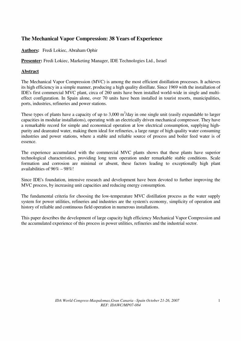
I. THE PROCESS The Mechanical Vapor Compression (MVC) distillation is inherently the most thermodynamically efficient
process of single-purpose thermal desalination plants. The thermodynamic efficiency is derived from the
application of the "heat pump" principle by a large volumetric flow compressor acting as the "heat pump",
which continuously recycles and keeps the latent heat exchanged in the evaporation and condensation steps
within the system [1, 2]. In this scheme, the heat required to evaporate part of the processed feed, which
flows on one side of a heat transfer surface, is supplied through the simultaneous condensation of the
distillate, on the other side of the surface (Figure 1).
Figure 1: MVC Schematic Process
The "heat pump" work, plus the fraction required for liquid pumping, is the only energy consumed by the
process. No additional heat is required, and no cooling water is needed for the heat rejection, as in other
distillation processes.
The heat generated by the compressor work is rejected in the outgoing product and brine streams that are
discharged at a higher temperature than the seawater feed. In order to maintain a higher operating
temperature, the incoming seawater feed is preheated by means of two plate heat-exchangers, by
exchanging heat with the outgoing streams.
IDA World Congress-Maspalomas,Gran Canaria –Spain October 21-26, 2007
REF: IDAWC/MP07-084
3
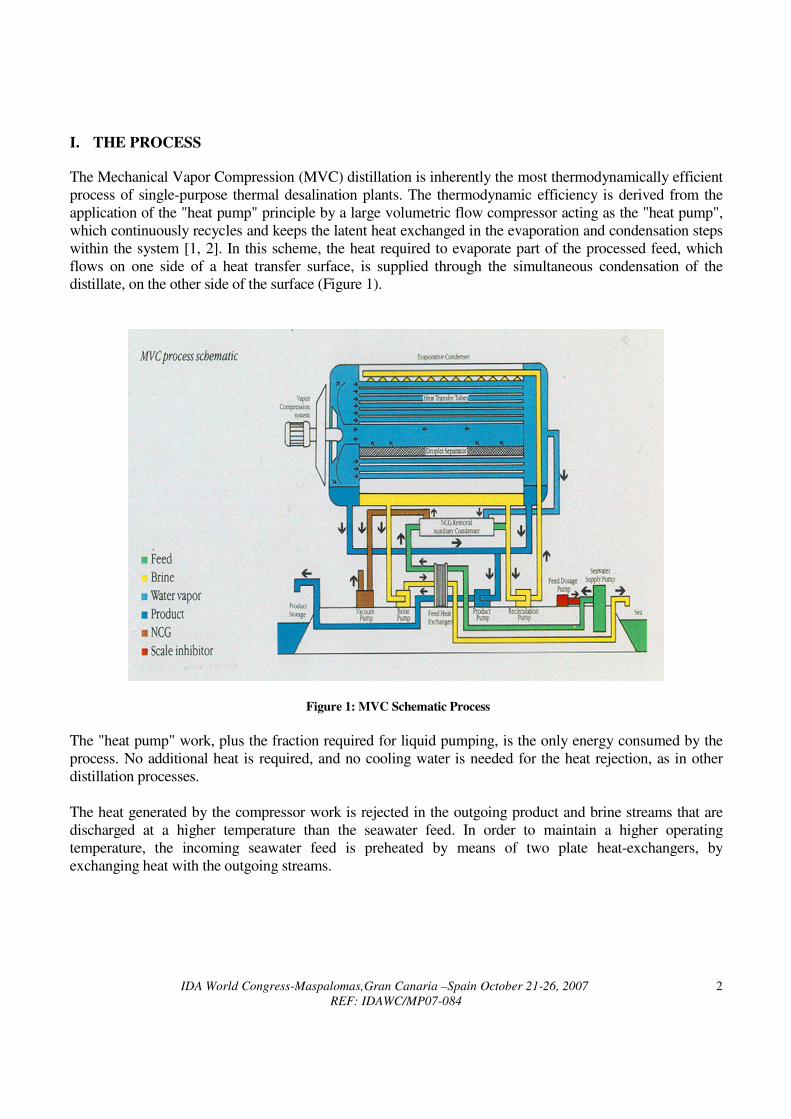
Many technological advances have been developed and implemented in IDE's Low-Temperature MVC
process, improving the economics of the desalination system [3]:
1. Development of a unique design of a falling film horizontal tube evaporator/condenser;
2. Low temperature operation (max. brine temperature of 70 Deg. C) (Figure 2);
3. Use of economical and durable materials of construction suitable for seawater applications, such as
Aluminum alloy heat transfer tubes, epoxy painted steel shells and plastic process piping;
4. Incorporation of a self-developed thin titanium blade centrifugal compressor, capable of handling a
large volumetric flow of water vapor at a relatively low cost;
5. Minimal requirements for intake and pre-treatment systems.
Brine Concentration / Temperature Brine Concentration / Temperature
Curve for Curve for LT LT -- MVC/MEDMVC/MED ProcessesProcesses
Figure 2: Brine Concentration/Temperature Curve for LT-MVC/MED Processes
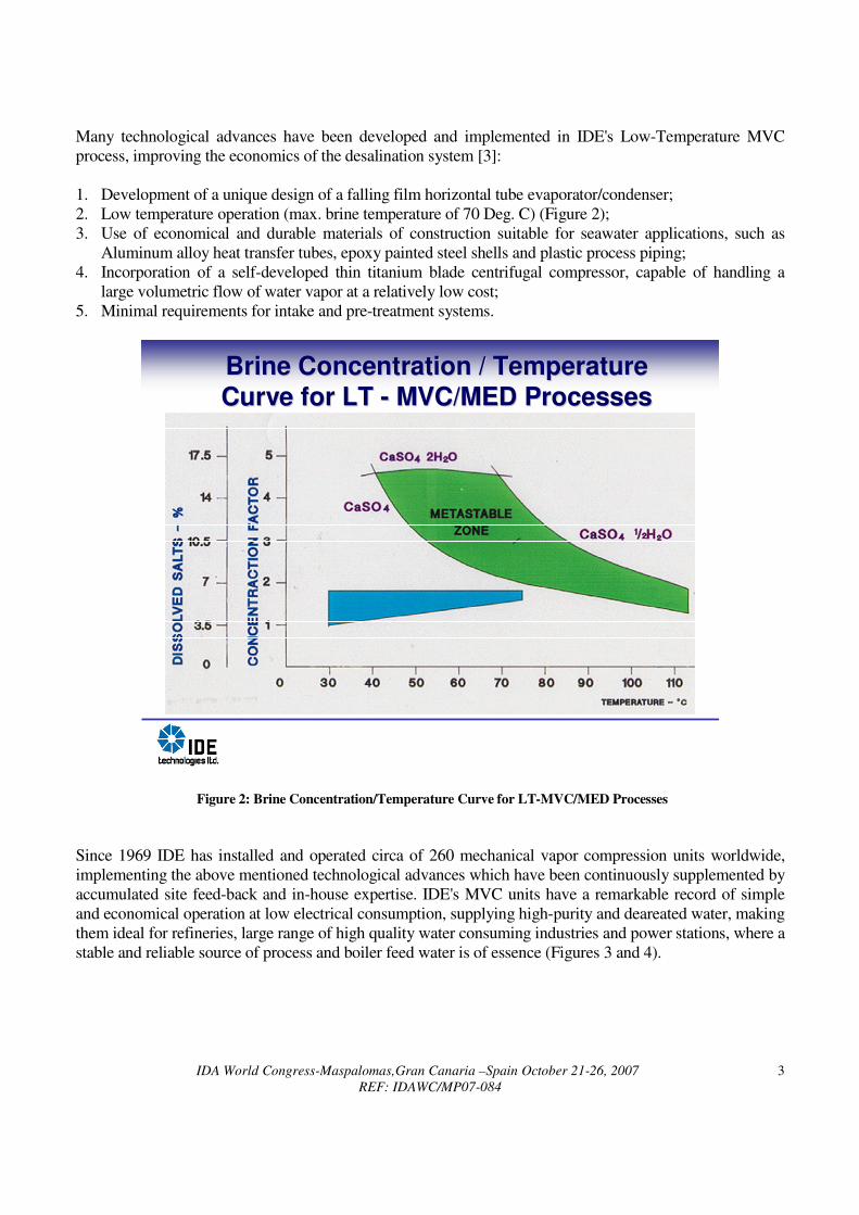
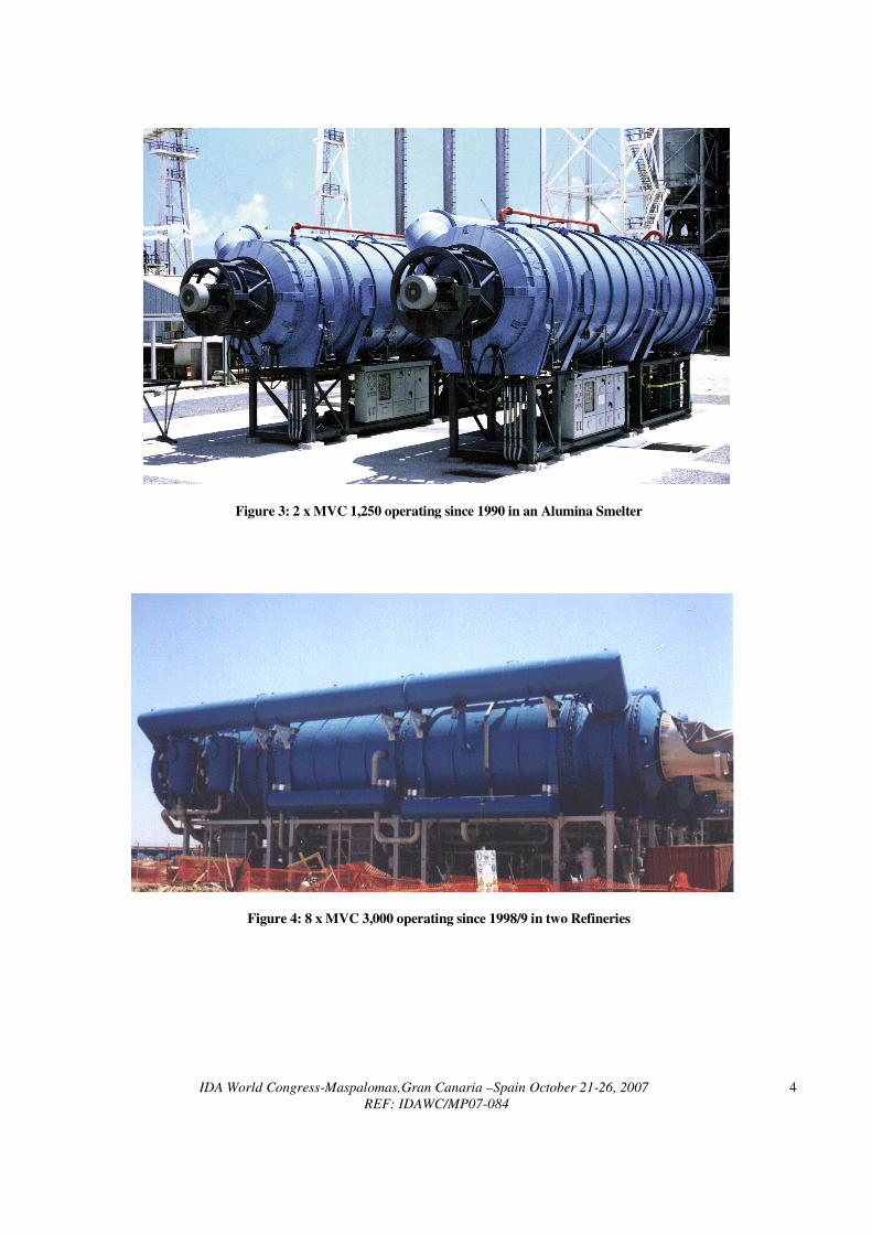
Since 1969 IDE has installed and operated circa of 260 mechanical vapor compression units worldwide,
implementing the above mentioned technological advances which have been continuously supplemented by
accumulated site feed-back and in-house expertise. IDE's MVC units have a remarkable record of simple
and economical operation at low electrical consumption, supplying high-purity and deareated water, making
them ideal for refineries, large range of high quality water consuming industries and power stations, where a
stable and reliable source of process and boiler feed water is of essence (Figures 3 and 4).
IDA World Congress-Maspalomas,Gran Canaria –Spain October 21-26, 2007
REF: IDAWC/MP07-084
4
Figure 3: 2 x MVC 1,250 operating since 1990 in an Alumina Smelter
Figure 4: 8 x MVC 3,000 operating since 1998/9 in two Refineries
IDA World Congress-Maspalomas,Gran Canaria –Spain October 21-26, 2007
REF: IDAWC/MP07-084
5
II. TECHNOLOGICAL DEVELOPMENT Along the years, intensive R&D has been invested to further improve the MVC process by increasing the
unit capacities and reducing energy consumption [4].
With regards to increasing unit capacities, the main limiting factors are: i) the physical dimensions of the
unit should remain within the confines that allow it to be transportable; ii) at low temperature operation the
volumes of vapor to be handled are large, thus demanding the development of high volumetric capacity
centrifugal compressors.
The prime energy consumer is the vapor compressor, accounting for over 80% of the total energy
requirements. Since in a compression system the energy consumption is related to mass flow, head and
efficiency, in order to reduce it, one shall focus on reducing either or both of the former parameters, while
increasing the compressor efficiency.
The compressor head required is determined by the "thermal driving force" required for transferring the
latent heat through the heat exchange metal barrier plus the losses like vapor flow losses and the boiling
point elevation.
The "driving force" required is a function of the amount of the heat transfer surface installed and the overall
heat transfer coefficient. Increasing the heat transfer capacity is achieved by increasing the number of
effects [5], which also increases the output for a given volumetric flow of the compressor, and by increasing
the size (diameter) of the effect (however limited by available transportation means).
The first generation plants already had a generous allocation of low cost aluminum alloy tubes. The main
consideration was to improve the effectiveness and compactness of the surface area installed. Considerable
development was invested into selecting the best configuration taking into account optimal wetting, liquid
film thickness, vapor velocity, condensate drainage, NCG purging and compactness.
As a result of these efforts, a considerable increase in the overall heat transfer coefficient has been achieved
and more heat transfer area was installed in a given cross-sectional area. Furthermore, by careful
mechanical redesign of the unit, the main vessel internal diameter was increased up to 4.8 m, while still
allowing land transportation of the vessel.
Larger MVC units are inherently superior compared to multiples of smaller units, yielding equivalent total
capacity, due to economies of scale [4].
In order to reduce the flow of vapor handled by the compressor per unit product considered, IDE
incorporated more than one evaporating/condensing effect per compressor. In a two or three effects plant,
the compressor throughput is approximately halved or one-third of that expected for a compressor in a
single effect MVC of the same capacity. On the other hand, the head to be developed by the compressor in a
multi-effect configuration is less than doubled or tripled; although the latent heat of condensation must be
transferred twice or tree folds through the heat exchange surfaces, and parasitic losses like vapor flow losses
shall be also taken in account, the multiple-effect configuration brings a considerable thermodynamic
advantage due the fact that the boiling point elevation achieves its maximum value only in one of the effects
where brine salinity is the highest, while in the remaining 1 or 2 effects, with lower brine salinity, the
boiling point elevation is lower than its maximum value.
IDA World Congress-Maspalomas,Gran Canaria –Spain October 21-26, 2007
REF: IDAWC/MP07-084
6
This qualitative analysis is sufficient to indicate that a two/three effect configuration provides a method of
overcoming the limiting factor imposed by compressor capacity, and should be more efficient than a single
effect system. In parallel, considerable attention was also given to the development of new compressors with higher
volumetric flow and head and in raising the overall efficiency of the vapor compression system [6].
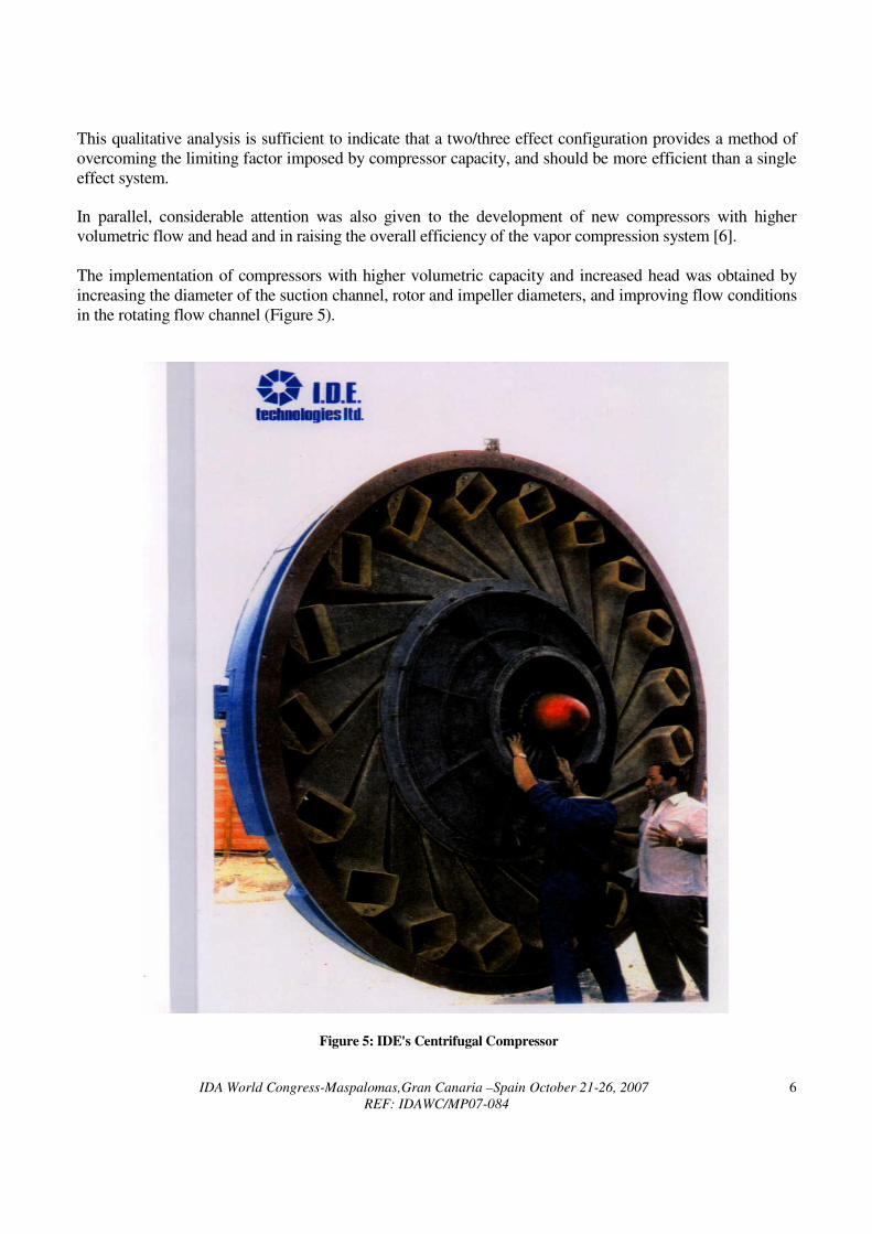
The implementation of compressors with higher volumetric capacity and increased head was obtained by
increasing the diameter of the suction channel, rotor and impeller diameters, and improving flow conditions
in the rotating flow channel (Figure 5).
Figure 5: IDE's Centrifugal Compressor
IDA World Congress-Maspalomas,Gran Canaria –Spain October 21-26, 2007
REF: IDAWC/MP07-084
7
The original compressor design had one rotor fitted with a set of blades having the inducer section as an
integral part of the blade in a single piece, and was developed specially to handle large volumetric flows at
relatively low differential pressures as required by the process. A considerable improvement in the vapor
compression system efficiency was achieved thanks to a two rotor concept mounted on a single shaft, one
rotor housing the compressor blades and the other housing the inducer blades, allowing for a more efficient
hydrodynamic configuration. Further improvements have been achieved thanks to modifications
incorporated on the shroud, vapor ducts, diffusion section and instrumentation. III. EXPERIENCE As previously shown, the main factor in increasing MVC capacity is by developing compressors with
higher volumetric flow and head. The higher head enables the utilization of more effects in the unit,
yielding more product for the same volumetric flow of the compressor. The increase in the number of
effects also provides more specific heat transfer area, and as explained before, reduces the average mean
effective boiling point elevation in the plant since only the last effect operates against the highest brine
salinity. In addition, the capacity of each individual effect can be further increased by using a more efficient
heat transfer surface such as smaller diameter or grooved tubes, optimal wetting and larger diameter vessel.
This would consequently decrease the specific energy consumed by the compressor.
Nevertheless, lowering specific energy has its limits. These would be set by the increase in the heat
exchanger required to pre-heat the feed due to the decrease of the thermal driving force in the evaporator
effects from 2.2°C to 1.2°C, corresponding to specific energy of 8 – 8.5 kWh/t and 6.9 kWh/t respectively.
In some cases, this problem could be partially solved by the introduction of waste heat into the system.
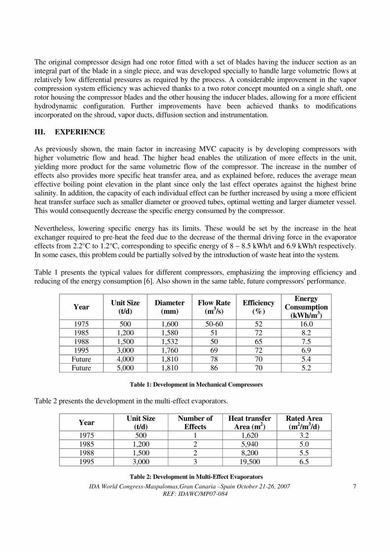
Table 1 presents the typical values for different compressors, emphasizing the improving efficiency and
reducing of the energy consumption [6]. Also shown in the same table, future compressors' performance.
Year Unit Size
(t/d) Diameter
(mm) Flow Rate
(m3/s)
Efficiency (%)
Energy Consumption
(kWh/m3)
1975 500 1,600 50-60 52 16.0
1985 1,200 1,580 51 72 8.2
1988 1,500 1,532 50 65 7.5
1995 3,000 1,760 69 72 6.9
Future 4,000 1,810 78 70 5.4
Future 5,000 1,810 86 70 5.2
Table 1: Development in Mechanical Compressors
Table 2 presents the development in the multi-effect evaporators.
Year Unit Size
(t/d) Number of
Effects Heat transfer
Area (m2)
Rated Area (m
2/m
3/d)
1975 500 1 1,620 3.2
1985 1,200 2 5,940 5.0
1988 1,500 2 8,200 5.5
1995 3,000 3 19,500 6.5
Table 2: Development in Multi-Effect Evaporators
IDA World Congress-Maspalomas,Gran Canaria –Spain October 21-26, 2007
REF: IDAWC/MP07-084
8
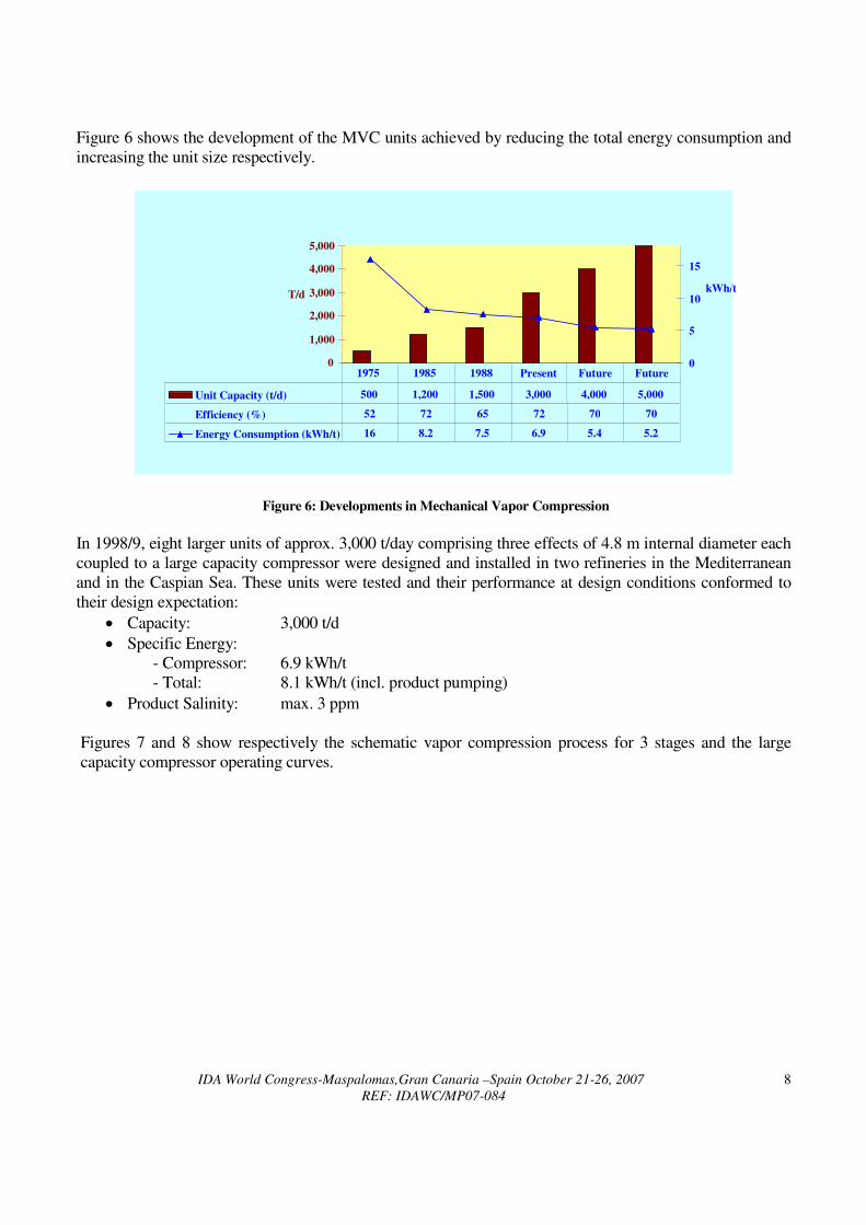
Figure 6 shows the development of the MVC units achieved by reducing the total energy consumption and
increasing the unit size respectively.
Figure 6: Developments in Mechanical Vapor Compression
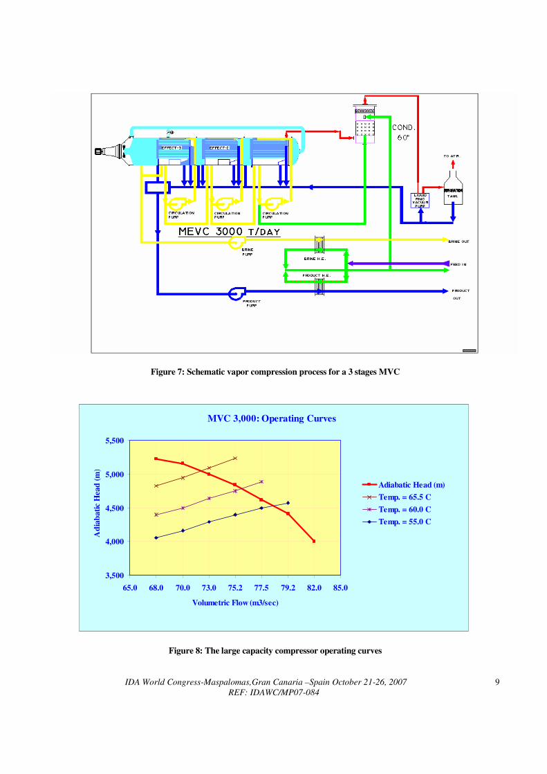
In 1998/9, eight larger units of approx. 3,000 t/day comprising three effects of 4.8 m internal diameter each
coupled to a large capacity compressor were designed and installed in two refineries in the Mediterranean
and in the Caspian Sea. These units were tested and their performance at design conditions conformed to
their design expectation:
• Capacity: 3,000 t/d
• Specific Energy:
- Compressor: 6.9 kWh/t
- Total: 8.1 kWh/t (incl. product pumping)
• Product Salinity: max. 3 ppm
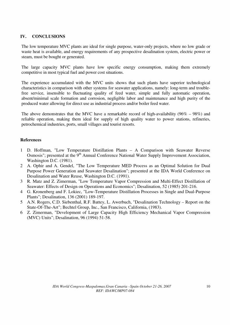
Figures 7 and 8 show respectively the schematic vapor compression process for 3 stages and the large
capacity compressor operating curves.
0
1,000
2,000
3,000
4,000
5,000
T/d
0
5
10
15
kWh/t
Unit Capacity (t/d) 500 1,200 1,500 3,000 4,000 5,000
Efficiency (%) 52 72 65 72 70 70
Energy Consumption (kWh/t) 16 8.2 7.5 6.9 5.4 5.2
1975 1985 1988 Present Future Future
IDA World Congress-Maspalomas,Gran Canaria –Spain October 21-26, 2007
REF: IDAWC/MP07-084
9
Figure 7: Schematic vapor compression process for a 3 stages MVC
MVC 3,000: Operating Curves
3,500
4,000
4,500
5,000
5,500
65.0 68.0 70.0 73.0 75.2 77.5 79.2 82.0 85.0
Volumetric Flow (m3/sec)
Ad
iab
ati
c H
ead
(m
)
Adiabatic Head (m)
Temp. = 65.5 C
Temp. = 60.0 C
Temp. = 55.0 C
Figure 8: The large capacity compressor operating curves
IDA World Congress-Maspalomas,Gran Canaria –Spain October 21-26, 2007
REF: IDAWC/MP07-084
10
IV. CONCLUSIONS The low temperature MVC plants are ideal for single purpose, water-only projects, where no low grade or
waste heat is available, and energy requirements of any prospective desalination system, electric power or
steam, must be bought or generated.
The large capacity MVC plants have low specific energy consumption, making them extremely
competitive in most typical fuel and power cost situations.
The experience accumulated with the MVC units shows that such plants have superior technological
characteristics in comparison with other systems for seawater applications, namely: long-term and trouble-
free service, insensible to fluctuating quality of feed water, simple and fully automatic operation,
absent/minimal scale formation and corrosion, negligible labor and maintenance and high purity of the
produced water allowing for direct use as industrial process and/or boiler feed water.
The above demonstrates that the MVC have a remarkable record of high-availability (96% – 98%) and
reliable operation, making them ideal for supply of high quality water to power stations, refineries,
petrochemical industries, ports, small villages and tourist resorts.
References
1 D. Hoffman, "Low Temperature Distillation Plants – A Comparison with Seawater Reverse
Osmosis"; presented at the 9th Annual Conference National Water Supply Improvement Association,
Washington D.C. (1981).
2 A. Ophir and A. Gendel, "The Low Temperature MED Process as an Optimal Solution for Dual
Purpose Power Generation and Seawater Desalination"; presented at the IDA World Conference on
Desalination and Water Reuse, Washington D.C. (1991).
3 R. Matz and Z. Zimerman, "Low Temperature Vapor Compression and Multi-Effect Distillation of
Seawater: Effects of Design on Operations and Economics"; Desalination, 52 (1985) 201-216.
4 G. Kronenberg and F. Lokiec, "Low-Temperature Distillation Processes in Single and Dual-Purpose
Plants"; Desalination, 136 (2001) 189-197.
5 A.N. Rogers, C.D. Siebenthal, R.F. Battey, L. Awerbuch, "Desalination Technology – Report on the
State-Of-The-Art"; Bechtel Group, Inc., San Francisco, California, (1983).
6 Z. Zimerman, "Development of Large Capacity High Efficiency Mechanical Vapor Compression
(MVC) Units"; Desalination, 96 (1994) 51-58.