the neuromorphic in this issue: engineerbibyk/ee720/nme1.pdf · • cnrs robotic flight guidance...
TRANSCRIPT

IFAT
MCU
RAM
DAC
DIO
RAM synapse
neuron addr.
DIO
DAC
presynaptic
parameters weightsynaptic
neuron addr.postsynaptic
MCU
drivingpotential(digital)
postsynapticneuron addr.
driving potential(analog)
incomingspike addr.
feed-forward
outgoingspike addr.
recurrentmode
mode
IFAT
ENGINEERThe Neuromorphic In this issue:
• Telluride: Call for applications• Smart building research at
ETH/Caltech• Wide dynamic range imaging
from Ben Gurion• University of Oslo on using the
time domain• Johns Hopkins research on
using the time domain inanalog circuits
• Caltech and MBARIcollaborate to see jellies
• Imperial College vision chipsfor biomedical imaging
• CNRS robotic flight guidance• Laboratory Notes:
The iLab Neuromorphic VisionC++ Toolkit from USC
• Library Essentials:Analog VLSI & Neural Systems
• Mark Tilden and WowWee Toysintroduce the Robosapien
Volume 1, Number 1 Spring 2004
Beyond address-event
communication: dynamically-
reconfigurable spiking neural
systemsLarge-scale artificial sensory information-pro-cessing systems that emulate biological intel-ligence when interfacing with their surround-ings have been the holy grail of neuromorphicengineering. The effort of our communityhas concentrated on modeling neural struc-tures and adaptive mechanisms in biology asmuch as it has on efficient implementationin real-time micropower hardware.
However, despite steady advances in thescaling of VLSI technology, which promisesto deliver more transistors on a single chipthan neurons in our brain, it is neither fea-sible nor advisable to integrate the full func-tionality of a complete nervous system on asingle chip. Early experimentation withneuromorphic systems revealed the need fora multi-chip approach and a communicationprotocol between chips to implement largesystems in a modular and scalable fashion.Thus, the address-event representation(AER) protocol was developed over a de-cade ago and quickly became a universal ‘lan-guage’ for neuro-morphic engineering sys-tems to communicate neural spikes betweenchips.1-7 However, AER is now used for func-
tions in addition to inter-chip communica-tion. The Silicon Cortex project proposed us-ing AER to connect detailed compartmentalmodels of neurons and synapses on multiplechips,8,9 and a few different groups have usedAER to implement synaptic connectivity.4-7
Here we will concentrate on our inte-grate-and-fire array transceiver (IFAT) chips,which can be used to implement large-scaleneural networks in silicon with both synap-tic connectivity and synaptic plasticity in theaddress-domain.10,11 The newest IFAT chip12
implements 2,400 silicon neurons, each witha single dynamically-programmable conduc-tance-like synapse: both the synaptic ‘con-ductance’ and the synaptic driving potentialcan vary for each incoming event. Rather thanhardwiring connections between cells, thenetwork architecture and synaptic parametersare stored off-chip in a RAM-based look-uptable (LUT). An external digital micro-con-troller (MCU) provides the appropriate sig-nals to configure synapses and route spikesto their respective targets via an asynchro-nous AER bus. A block diagram of the sys-tem is shown in Figure 1.
During normal opera-tion, the event-drivenmicrocontroller is acti-vated when a presynapticneuron generates a spike.The cell’s address is usedas an index into the LUTand the data stored at thatlocation in RAM specifiesone or more postsynaptictargets with their associ-ated synaptic weights anddriving potentials. TheMCU then provides sig-nals to the IFAT to con-figure each synapse andsends the events serially.Any postsynaptic spikesgenerated by this processcan either be sent back to
the IFAT (in recurrent mode) or sent off-chip(in feed-forward mode), depending on thedata stored in RAM. Additionally, updates tothe network can be implemented by modify-ing the LUT according to a spike-based learn-ing rule computed by the MCU.11
A printed circuit board (Figure 2) inte-
grates the components of the IFAT system,including 9,600 neurons on four IFAT chips,128MB of non-volatile SRAM, a high-speed8bit voltage DAC, a 200MHz FPGA, and a32bit digital I/O (DIO) interface. The DACis used to control synaptic driving potentials,while synaptic weights are specified by threeseparate fields in the LUT: one each for thesize of the postsynaptic potential, the num-ber of events to send, and the probability ofevent transmission. External AER-complianthardware or a peripheral computer interface
Vogelstein, continued p. 9
Figure 2. Printed circuit board integrating allcomponents of the IFAT system.
Figure 1: Blockdiagram of IFATsystem.

The Neuromorphic Engineer 2 Volume 1, Issue 1, 2004
Neuromorphic Engineering Workshop:
call for applications
We invite applications for a three-week sum-mer workshop that will be held in Telluride,Colorado, from Sunday, June 27 to Satur-day, July 17, 2004. The application deadlineis Friday, March 19 (see full application in-
structions on the web1). The 2003 workshopand summer school, sponsored by the Na-tional Science Foundation, the WhitakerFoundation, the Office of Naval Research,the Defense Advanced Research ProjectsAgency, and the Center for NeuromorphicSystems Engineering at the California Insti-tute of Technology, was an exciting event anda great success. We strongly encourage inter-ested parties to browse through the previousworkshop web pages.2
GoalsCarver Mead introduced the term ‘neuro-morphic engineering’ for a new field basedon the design and fabrication of artificial neu-ral systems—such as vision systems, head-eyesystems, and roving robots—whose architec-ture and design principles are based on thoseof biological nervous systems. The goal ofthis workshop is to bring together bothyoung investigators and more establishedresearchers from academia, as well as theircounterparts in industry and national labo-ratories, to work on both neurobiological andengineering aspects of sensory systems andsensory-motor integration. The focus of theworkshop will be on active participation, withdemonstration systems and hands-on expe-rience for all who take part.
Neuromorphic engineering has a widerange of applications: from nonlinear adap-tive control of complex systems to the de-sign of smart sensors. Many of the funda-mental principles in this field, such as the useof learning methods and the design of paral-lel hardware (with an emphasis on analog andasynchronous digital VLSI), are inspired bybiological systems. However, existing appli-cations are modest and the challenge of scal-ing up from small artificial neural networksand designing completely autonomous sys-tems at the levels achieved by biological sys-tems lies ahead. The assumption underlyingthis three-week workshop is that the nextgeneration of neuromorphic systems wouldbenefit from closer attention to the principlesfound through experimental and theoreticalstudies of real biological nervous systems aswhole systems.
FormatThe three-week summer workshop will in-clude background lectures on systems neu-roscience (in particular learning, oculo-mo-tor and other motor systems and attention),practical tutorials on analog VLSI design,small mobile robots (Koalas, Kheperas,LEGO robots), hands-on projects, and spe-
cial interest groups. Participants are requiredto take part and possibly complete at leastone of the projects proposed. They are fur-thermore encouraged to become involved inas many of the other activities proposed asinterest and time allow. There will be twolectures in the morning that cover issues thatare important to the community in general.Because of the diverse range of backgroundsamong the participants, the majority of theselectures will be tutorials, rather than detailedreports of current research. These lectures willbe given by invited speakers.
Participants will be free to explore andplay with whatever they choose in the after-noon. Project/interest groups meet in the lateafternoons and after dinner. Early afternoonthere will be tutorial on a wide spectrum oftopics including analog VLSI, mobile robot-ics, auditory systems, central pattern genera-tors, and selective-attention mechanisms.
Projects that are carried out during theworkshop will be centered in a number ofworking groups, including: active vision,audition, motor control, central- pattern gen-erator, robotics, multichip communication,analog VLSI, and learning. The active per-ception project group will emphasize visionand human sensory-motor coordination. Is-sues to be covered will include spatial local-ization and constancy, attention, motor plan-ning, eye movements, and the use of visualmotion information for motor control. Thecentral pattern generator group will focus onsmall walking and undulating robots. It willlook at characteristics and sources of partsfor building robots, play with working ex-amples of legged and segmented robots, anddiscuss CPGs and theories of nonlinear os-cillators for locomotion. It will also explorethe use of simple analog VLSI sensors forautonomous robots. The robotics group willuse rovers and working digital vision boardsas well as other possible sensors to investi-gate issues of sensorimotor integration, navi-gation and learning. The audition group aimsto develop biologically-plausible algorithmsand aVLSI implementations of specific au-ditory tasks such as source localization andtracking and sound pattern recognition.Projects will be integrated with visual andmotor tasks in the context of a robot plat-form. The multichip communication projectgroup will use existing interchip communi-cation interfaces to program small networksof artificial neurons to exhibit particular be-haviors such as amplification, oscillation, and
Telluride, continued p. 11
The Neuromorphic
engineeris published by the
Editor
Sunny BainsImperial College [email protected]
Editorial Assistant
Stuart [email protected]
Editorial Board
Avis CohenRalph Etienne-Cummings
Rodney DouglasTimothy HoriuchiGiacomo Indiveri
Christof KochShih-Chii Liu
Shihab ShammaChris Toumazou
André van Schaik
Available on the web at:
http://www.ine-web.org
The Institute ofNeuromorphic EngineeringInstitute for Systems Research
AV Williams BldgUniversity of Maryland
College Park, MD 20742http://www.ine-web.org

The Neuromorphic Engineer 3 Volume 1, Issue 1, 2004
should not intrude on the user. In this article weparticularly highlight the problem1 from a ma-chine-learning perspective.
Unsupervised learning and controlWe tackle the learning problem in several stages.All knowledge that the system has about its goalsand users is stored as fuzzy logic2 rules (in arulebase). These rules are continually adaptedbased on feedback from the environment. Anumber of agents,3 each responsible for a smallpart of the whole decision space, use individualrulebases for decision-making. Using fuzzy ruleshas the advantage that the rulebase, althoughcompletely automatically constructed by thelearning algorithm, is easily read and modifi-able by humans.
Two-stage memory and decision processThe inherent non-stationarity and noisinessof user interactions with the building makeit difficult to acquire stable, long-termknowledge. On one hand, the building mustbe able to retain and recognize long-termoverall patterns of behavior; but on theother hand it must also react to short-termchanges in requirements without destroy-ing such long-term knowledge. Motivatedby biological systems, we use a two-stagememory process: short-term (STM) andlong-term (LTM) memory.4 Newly-acquiredknowledge remains in STM and does notbecome part of LTM before it is confirmedand generalized. STM changes rapidly basedon user demand and always gets precedenceover LTM during day-to-day operation.However, if the former is discarded after ashort time if it does not get incorporatedinto latter. Knowledge transformation from
Fuzzy LogicController
Temporary Rulebase (STM)
DecisionEvaluation
Decision and Learning Unit (DLU)
Sensor InputsPresenceDaylightLight SwitchesBlind SwitchesLight StatusBlind StatusTemperaturIlluminanceDaytimeRadiation
Learning
Long-Term Memory (LTM)
Fuzzy LogicController
GeneticAlgorithm
OutputLight ActionBlind Action
Generalized Rulebase
Ver
ifica
tion
Unsupervised learning and control provide
ambient intelligence to smart buildings
Buildings are changing their nature fromstatic structures of bricks and mortar to dy-namic work and living environments that
actively support and assist their inhabitants.These new buildings are expected to behaveintelligently. In addition, to satisfying theneeds of its inhabitants, a building is an ac-tive, autonomous entity that pursues its owngoals (energy consumption, security). Tofulfill this goal, a building must continuallytake decisions: but specifying rules that de-scribe which actions to take, at which time,and because of which conditions, is com-plex and time consuming.In addition, these rules haveto be changed constantly,because preferences andneeds of users change. Thebuilding thus needs to learnits own rules of behavior,and continually adapt them,based on feedback from itsoccupants.
Engineering such a systemposes a number of challenges.Decisions must be made innear-real time. The systemmust have a way to interactwith its users to obtain feed-back. On the other hand, it
Office 1 Office 2
Lab 1Lab 3
Presence
Light
Blinds
Outside Sensors
Fieldbus
IP
Key
Gateway
Intelligent Building Control
DLU
DLU
DLU
DLU
DLU
Figure 1. The floor of a typical buildingstructured into rooms. All sensors and effectorsare wired to a common fieldbus network. Agateway allows the agents to access the fieldbusnetwork.
STM to LTM, as in natural systems, takesplace transparently: in parallel to decisionmaking and learning. For efficient generali-zation of knowledge, a genetic algorithm5
is used (see Figure 2). This serves as an effi-cient mechanism to retain long-term knowl-edge in spite of inherent contradictions infeedback that occur in the short-term. Thisis a two-way process: knowledge in LTM,as in STM, is discarded if it is not neededanymore, or if it contradicts new facts. Thisproperty is essential because of the non-stationarity of the environment.
We have been running various versionsof this system in a real building to evaluateits performance. Initial results are promis-ing and show that the system is able to im-prove the inhabitants’ comfort1 and mini-mize energy consumption.
Ueli Rutishauser*†, Jonas Trindler†and Rodney Douglas†*Computation and Neural SystemsCalifornia Institute of Technology†Institute of NeuroinformaticsETH/University of ZurichE-mail: [email protected] [email protected]://www.ini.unizh.ch/~trindler/abi
References1. U. Rutishauser, J. Joller, R.J. Douglas, Control and learn-ing of ambience by an intelligent building, IEEE T. on Sys-tems, Man and Cybernetics, submitted, 2004.2. R. Fuller, Neural fuzzy systems, Springer, Berlin, 2000.3. G. Weiss, Multiagent systems, The MIT Press, Cam-bridge, 2001.4. H. Zhou, CSM: A Computational Model of CumulativeLearning, Machine Learning. 5, pp 383-406, 1990.5. M. Mitchell, An introduction to Genetic Algorithms,The MIT Press, Cambridge, 1998.
Figure 2. Decisions aretaken based on fuzzy logicrules, which are stored ineither long- or short-term
memory. Feedback from theenvironment is used tocontinually adapt the
rules.
Send the Editor ideas for the next issue by:
19 July 2004
Next issue copy due 17 September 2004.

The Neuromorphic Engineer 4 Volume 1, Issue 1, 2004
Interest in technologies that can help improveimage sensors—in terms of cost, noise anddynamic range—is growing as quickly as themarket for them. Dynamic range (DR) quan-tifies the ability of a sensor to image high-lights and shadows. If we define the dynamicrange of the sensor as 20log(S/N), where S is
the maximal signal value and N is the sensornoise, the typical image sensors will have avery limited dynamic range, about 65-75dB.Thus, dynamic range can be increased in twoways: noise reduction can expand dynamicrange for darker regions, and raising the in-cident-light saturation level can improve itfor brighter regions.
Wide dynamic range
(WDR) imaging
Figure 1. Imaging pipeline, image sensorarchitecture, and work principle.
Figure 2. (a) Scene observed with a traditionalCMOS APS sensor. (b) Scene observed with ourin-pixel auto exposure CMOS APS sensor
The human visual system (HVS) hasoverall dynamic range of about 200dB, butit cannot operate over the entire (enormous)range at the same time. Using the phenom-enon called brightness adaptation, it adapts
for various conditions by changing its over-all sensitivity. Thus, it still has a high dynamicrange even at a single adaptation level. Thisis achieved with the assistance of three majormechanisms:1 change in pupil diameter, neu-ral adaptation, and photochemical adapta-tion.
It is obvious that these HVS mechanismsare very complicated and cannot be exactlyemulated. Nevertheless, we can try to ap-proach some of them by designing smartimage sensors with algorithms that allow anadaptive widening of the dynamic range. Theoverall task for WDR imaging can be dividedinto two distinguished stages: image capture,preventing the loss of scene details; and im-age compression, allowing image represen-tation on conventional computer screens. Thefirst stage is a challenge mainly for image-
sensor designers,while the secondstage can be per-formed also in soft-ware.
WDR imagingHerein, we presentone of the possiblesolutions for dy-namic range exten-sion in CMOS activepixel sensors (APS).2
As in a traditionalCMOS APS, this imager is constructed of atwo-dimensional pixel array, with randompixel-access capability and a row-by-row read-out rolling-shutter method. Each pixel con-tains an optical sensor to receive light, a resetinput, and an electrical output representingthe illumination received. This imager imple-ments a simple function for saturation detec-
tion, and is able to control the light exposuretime on a pixel-by-pixel basis, resulting in nosaturation. The pixel value can then be deter-mined as a floating-point representation, simi-lar to brightness adaptation in the HVS. Todo so, the outputs of a selected row are readout through the column-parallel signal chainand, at certain points in time, are also com-pared with an appropriate threshold value,as shown in Figure 1.
If a pixel value exceeds the threshold—i.e. the pixel is expected to be saturated at theend of the exposure time—the reset is givenat that time to that pixel. The binary infor-mation concerning the reset (i.e., if it is ap-plied or not) is saved in a digital storage forlater calculation of the scaling factor. Thus,in order to emulate the HVS, we can repre-sent the pixel output in the following float-ing-point format: M⋅2EXP. Here, the mantissa(M) represents the digitized pixel value, andthe exponent (EXP) represents the scalingfactor. This way, a customized, linear, largeincrease in the dynamic range is achieved.
Figure 2 compares an image captured bya traditional CMOS imager and by the auto-exposure system presented here. In Figure2(a), a scene is imaged with a strong lighthitting the object: hence, some of the pixelsare saturated. At the bottom of Figure 2(b),the capability of the auto-exposure sensor forimaging the details of the saturated area inreal time is shown. Since the display device islimited to eight bits, only the most relevanteight-bit part (i.e., the mantissa) of the thir-teen-bit range of each pixel is displayed here.The exponent value, which is different fordifferent areas, is not displayed here.
WDR compressionTo allow image representation on conven-tional computer screens, compression of theacquired dynamic range is required. The re-sulting image should be as natural as pos-sible, and should contain most of the details(both in bright and in shadowed areas) thata human observe would see if watching atthe scene. Following space limitations, pleasesee the reference for more details.3
Alexander Belenky, Evgeny Artyomov,Alexander Fish, and Orly Yadid-PechtVLSI Systems CenterBen-Gurion Universityhttp://www.ee.bgu.ac.il/~Orly_lab/
References1. A. C. Guyton, Textbook of Medical Physiology,W. B. Saunders Co, 8th edition, 1991.2. O. Yadid-Pecht, A. Belenky, Autoscaling CMOSAPS with customized increase of dynamic range, Proc.IEEE ISSCC, San- Francisco, California, February 4-7, 2001.3. M. Hersccovitz, E. Artyomov, O. Yadid-Pecht, Im-proving the global impression of brightness of the MultiScale Retinex algorithm for wide dynamic range pictures,Proc. SPIE 5017, pp. 393-405, 2003.

The Neuromorphic Engineer 5 Volume 1, Issue 1, 2004
A :=Vout
Vin=
C1I2
C2I1
On using the time domain for analog signal
representation in electronic circuitsThere is an ever-growing interest within thefields of neurophysiology—as well as withincoding theory and signal processing—intothe particular information transmissionmethod employed by most neurons: spikes.Many models used today regard those volt-
age pulses as uniform events where only theoccurrence of an event from a particular neu-ron at a particular moment in time matters.This signal representation offers many pow-erful encoding schemes, where informationcan be encoded into spike-event patternsover time and space. An analog value, forinstance, can be encoded as an interval be-tween two spikes.
Time-domain encoding and processingcan also be used to advantage in electronicdevices. So, besides representing signals withcurrents or voltages, they can just as well berepresented with time intervals. This is, ofcourse, not unknown in analog electronics,but since time-domain signals also consumetime, they are not widely popular. They do,however, start to be increasingly importantin neuronal models and, thus, in neuro-morphic electronics.
The concept is not just limited to theimitation of biological functions, but canalso be applied to more classical computa-tions. Let us consider two simple examplesfor an analog division and multiplication cir-cuit. A voltage can be divided by a currentby measuring the interval it takes to depletea capacitor from that voltage down to a zeroreference. The output of that circuit is thenthat time interval, represented (for example)by a pulse width (first stage in Figure 1).Alternatively, a current can be multiplied Häfliger, continued p. 9
Figure 2. A weight update circuit for a spike-based learning rule.
∆w = αc − βw
with an interval by integrating that currenton a capacitor during that interval. Thus,the output can be read as the voltage onthat capacitor (second stage in Figure 1).These two stages in sequence can be de-scribed as an amplifier with voltage input
and output: it samples the input voltagewhen triggered (signal g), and its gain A isset by the ratio of two bias currents I
1 and
I2.
Equation 1
The label Vdd-Vref
refers to a voltage thatcan be derived on chip from V
ref and makes
a NAND-like comparator switch as the volt-age on C
1 becomes smaller than‘V
ref. Both g
and its inverse are digital-level signals thatstart the computation and remain active dur-ing it. The duration of g limits the maximalrange for the interval T and, thus, gives alower limit for I
1.
This amplifier circuit has a wide inputrange, i.e. between V
ref and Vdd, and it can
be set to a wide range of different gains A,both greater and smaller than 1. It only con-sumes power when triggered, and internalcurrents are integrated over time, which re-duces the total error. A source for error inthe time domain will be the relatively slowswitching of the pulse-generating compara-tor circuit. Because of the internal time-do-main representation, it is not suited for fastor continuous computations. It is, however,well suited for event-triggered computationswith a limited event frequency. Good ex-amples of these are all kinds of spike-signal-processing neuromorphic circuits.
In a chip layout that is currently in pro-duction, two of these amplifier circuits werecombined (Figure 2) to compute the weight
updates for a spike-based learning rule.1-4 Thespecific rule implemented here5 changes a syn-aptic weight for every output spike (g is theneuron’s output pulse, lasting 1ms) of theneuron according to Equation 2.
Equation 2
There is an amplifier circuit for each multi-plicative term. Both a and b are constantparameters and are the gain set by the twobias currents (I
1 and I
2 in Equation 1). I
1
(set by VI_b1
) is shared by the two first stages.In practice only the second parameter cur-rents (as set by V
a and V
b) are used to set a
and b. An average value of the recent inputactivity on this synapse is containted in c,and both it and (obviously) w are dynami-cally-changing variables that are representedas voltages in the circuit. The second stagesof the amplifiers have been modified totransform the pulses into charge packagesthat are added and subtracted from theweight. On the real chip, the storage capaci-tor is actually a weak multi-level memorycell that is better suited for long-term re-tention of the weight voltage.6
These simple examples illustrate thattime-domain signal representation can beused to advantage in electronic circuits, pri-marily to implement functions of neurophysi-ological models (like feature based motion-
processing7 or sound-localization8 systems),but also for all kinds of more basic functions.Other examples that have been published are,for example, a max circuit9 and a delay com-parator.10
We do not claim that similar methodshave never been applied before. But lookingat time consumption as a resource, rather than
Figure 1. A voltage amplifier with internaltime-domain representation.

The Neuromorphic Engineer 6 Volume 1, Issue 1, 2004
The art of
seeing jellies
at sea on shore
ROV with HDTV camera
video recorded on digital tapes
manual annotation
video capture
automatic
processing
read digital tapes
The oceans contain a wealth of living creaturesthat account for a large amount of the biomasson our planet. How can we assess the kinds andnumbers of animals in the oceanic water col-umn? For more than a century, the traditionalapproach has been to tow nets behind ships.This method is limited in its spatial resolution,and because of the design of the nets, gelati-nous animals (such as jellies, previously knownas jelly fish) are destroyed and, hence, under-sampled. Today, remotely-operated underwatervehicles (ROVs) provide an excellent alterna-
tive to nets for obtaining quantitative data onthe distribution and abundance of oceanic ani-mals.1
Using video cameras, it is possible to makequantitative video transects (QVT) through thewater, providing high-resolution data at the scaleof the individual animals and their natural ag-gregation patterns. However, the current manualmethod of analyzing QVT video by trained sci-entists is very labor intensive and poses a seri-ous limitation to the amount of data that can beobtained from ROV dives. To overcome thisbottleneck in analyzing ROV dive videos wehave developed an automated system for de-tecting and tracking animals for subsequent iden-tification, based on neuromorphic vision algo-rithms.2 These tasks are difficult due to the lowcontrast of many translucent animals and dueto debris (known as ‘marine snow’) clutteringthe scene.
Onboard the research vessel, the HDTVvideo signal from the ROV’s broadcast-qualitycameras is recorded on a digital BetaCam videodeck. Back on shore, the videos are converted
to a computer-readable format, and some ge-neric pre-processing is performed for each frame,such as subtracting the background, smooth-ing scan lines, and global contrast enhancement.
For the crucial detection step, we use anextended version of the Itti & Koch saliency-based attention algorithm3 (see also Itti’s articlein this issue). For this neuromorphic detectionsystem for salient objects, each input frame isdecomposed into seven channels for intensitycontrast: red/green and blue/yellow double coloropponencies, and four spatial orientations (0˚,45˚, 90˚, and 135˚) at six spatial scales, yield-ing 42 ‘feature maps’. To improve the detec-tion of faint, elongated animals, we introducedan additional across-orientation normalizationstep for the orientation filters, which is inspiredby local interactions of orientation-tuned neu-
rons in the primary visual cortex.After iterative spatial competition for sa-
lience within each map, only a sparse numberof locations remain active and all maps are com-bined into a unique ‘saliency map’. This isscanned by the focus of attention in order ofdecreasing saliency, through the interaction be-tween a winner-take-all neural network (whichselects the most salient location at any giventime) and an inhibition-of-return mechanism(transiently suppressing the currently-attendedlocation from the saliency map).3 Once salienttargets have been detected, they are tracked fromframe to frame using linear Kalman filters4 forthe x and the y coordinates of the apparent mo-tion of the objects in the camera plane: this as-sumes motion with constant acceleration. Thisis a good assumption for the constant-speed-heading motion of ROVs while obtainingQVTs.
Normally, tracking multiple targets at thesame time raises the problem of assigning mea-surements to the correct tracks. Since ourneuromorphic detection algorithm only selects
the most salient objects, however, we obtain asparse number of objects whose predicted loca-tions are usually separated far enough to avoidambiguities. If ambiguities occur, we use a mea-sure based on the distance of the objects fromthe predictions of the trackers and the size ratioof the detected and the tracked objects. Everycouple of frames, the scene is again scanned forsalient targets that are not already being tracked,and new trackers are initiated for these.
For each tracked object we obtain a binarymask that allows us to extract a number of low-level properties such as the object size, the sec-ond moments with respect to the centroid, themaximum luminance intensity, the average lu-minance intensity over the shape of the object,and its aspect ratio. We use these features tobroadly classify the detected objects into those
that are interesting for the scien-tists, and those that are debris.Since the occurrence of visible ani-mals in the video footage is typi-cally sparse in space and time, wecan identify many frames that donot contain any objects of interest.By omitting these frames andmarking candidate objects, we canenhance the productivity of humanvideo annotators and/or cue a sub-sequent object classification mod-ule.
Our attentional selection andtracking system shows very prom-ising results for transects fromROV dives that have been ana-lyzed by human annotators already.This module is only the first steptowards an integrated neuro-morphic video annotation systemthat will consist of an object classi-fication module and control mod-
ules for pan/tilt/zoom cameras: these in addi-tion to the attentional module. This integratedsystem will be able to count the most commonanimals fully automatically.
Dirk Walther* and Duane Edgington†*California Institute of TechnologyE-mail: [email protected]†Monterey Bay Aquarium Research InstituteE-mail: [email protected]://www.mbari.org/aved
References1. B.H. Robison, The coevolution of undersea vehicles anddeep-sea research, Marine Technology Society J. 33, pp.69-73. 2000.2. D. Edgington, D. Walther, K.A. Salamy, M. Risi, R.E.Sherlock, and C. Koch, Automated Event Detection in Un-derwater Video, Proc. MTS/IEEE Oceans Conf., SanDiego, California, 2003.3. L. Itti, C. Koch, and E. Niebur, A model of saliency-based visual attention for rapid scene analysis, IEEE Trans.on Pattern Analysis and Machine Intelligence 20 (11),pp. 1254-1259, 1998.4. R.E. Kalman and R.S. Bucy, New Results in LinearFiltering and Prediction Theory, J. of Basic Engineering83 (3), pp. 95-108, 1961.
Figure 1. The process flow for recording the video material at sea and processing it on shore either manually orautomatically.
The Neuromorphic Engineer 7 Volume 1, Issue 1, 2004
Neuromorphic electronics for real-time
biomedical image processing
Algorithms for determining edges and con-tours,1 and for computing object position,size, and centroid, have been well establishedin software.2 However, stand-alone imple-mentations of such systems remain limitedby the high power dissipation and modularorganization of conventional electronics.Such schemes require an external digital cam-era streaming the scan to a DSP or embed-ded PC that runs the image-processing soft-ware.
A new breed of neuromorphic3 or bio-logically-inspired vision chips is emerging thatcombine the imaging and front-end filteringwith higher-order processing. Monolithicsystems realized in standard technologies canprovide low-cost and power-efficient solu-tions by using massively-parallel architecturesand integrating the processing with the pixelcircuitry. This approach prevents the need forthe heavy communication bandwidths thatare usually essential for real-time processing,as well as reducing power dissipation in theprocessing core. With use of novel weak-in-version circuits,4 real-time operation is nowa realistic prospect.
ORASIS is a vision chip based on theseprinciples, inspired by the unparalleled com-putational efficiency of neurobiology. Itimplements a novel, hybrid-neuromorphic-and-synthetic distributed algorithm5 for theanalysis of microscopic cellular populations.The object segmentation part works as fol-lows. First, continuous-time edge-detectionprovides the input for the contour-determi-nation circuitry. When the contour hasformed, a signal is initiated that fills inwards
Table 1. Target design specifications for ORASIS cell and system levelhardware implementation.
Figure 1. Computer simulation results of thebio-pulsating contour reduction algorithm,with snapshots taken at regular time intervalsat the propagation delay of the processing.
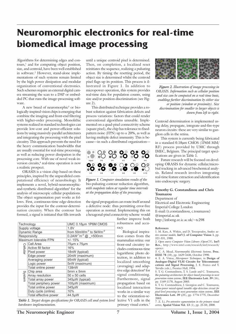
Figure 2. Illustration of image processing inORASIS. Information such as cellular positionand size can be computed on a real-time basis,enabling further discrimination by either size
or position (window or proximity). Sizediscrimination for smaller to larger objects is
shown from left to right.
until a unique centroid pixel is determined.Then, on completion, a localized resetreinitiates the sequence, realizing a pulsatingaction. By timing the resetting period, theobject size is determined whilst the centroidpixel flags up its position. This process is il-lustrated in Figure 1. In addition tomicropower operation, this system providesreal-time data for population counts, usingsize and/or position discrimination (see Fig-ure 2).
This distributed technique provides a ro-bust solution against fabrication defects andprocess variations: factors that could renderconventional algorithms unusable. Imple-mented on a quad-pixel connectivity scheme(square pixel), the chip has tolerance to fixed-pattern noise (FPN) up to ± 20%, as well ashaving multiple defect immunity. This is be-cause—in such a distributed organization—
the signal propagation can route itself arounda defective node: thus permitting error-freeoperation as normal. Implementing this ona hexagonal-pixel connectivity scheme would
further improve bothrobustness and accu-racy.
Biological inspira-tion comes from themammalian retina: ourfront-end circuitry in-cludes continuous-timelogarithmic photo de-tection, in addition tolocalized smoothing(averaging) and adap-tive edge detection6 forsignal conditioning.Furthermore, signalpropagation based onlocalized interactionworks in a similar wayto the orientation-se-lective V1 cells in theprimary visual cortex.7
Centroid determination is implemented us-ing delay, propagate, integrate-and-fire-typeneuron circuits: these are very similar to gan-glion cells in the retina.
This system is currently being fabricatedin a standard 0.18µm CMOS (1P6M MM/RF) process provided by UMC throughIMEC, Belgium. The principal target speci-fications are given in Table 1.
Future research will be focused on devel-oping ORASIS for dynamic cellular/micro-bial tracking in advanced biochemical analy-sis. Related research involves integratingreal-time feature extraction and identificationinto endoscopic surgery.
Timothy G. Constandinou and ChrisToumazouDepartment ofElectrical and Electronic EngineeringImperial College LondonE-mail:{t.constandinou, c.toumazou}@imperial.ac.ukhttp://infoeng.ee.ic.ac.uk/~tc298
References1. M. Kass, A. Witkin, and D. Terzopoulos, Snakes: ac-tive contour models, Int’l J. of Computer Vision 1, pp.321-331, 1988.2. Open source Computer Vision Library (OpenCV), Int’lRes., http://www.intel.com/research/mrl/research/opencv.3. C. A. Mead, Neuromorphic Electronic Systems, Proc.IEEE 78 (10), pp. 1629-1636, October 1990.4. E. A. Vittoz, Micropower Techniques, in Design ofAnalogue-Digital VLSI Circuits for Telecommuni-cations and Signal Processing, J. E. Franca and Y.Tsividis (eds.), Prentice Hall, 1994.5. T. G. Constandinou, T. S. Lande and C. Toumazou,Bio-pulsating architecture for object-based processing in nextgeneration vision systems, IEE Electronics Lett. 39 (16),pp. 1169-1170, August 2003.6. T. G. Constandinou, J. Georgiou and C. Toumazou,Nano-power mixed-signal tunable edge-detection circuit forpixel-level processing in next generation vision systems, IEEElectronics Lett. 39 (25), pp. 1774-1775, December2003.7. Z. Li, Pre-attentive segmentation in the primary visualcortex, Spatial Vision Vol. 13 (1), pp. 25-50, 2000.

The Neuromorphic Engineer 8 Volume 1, Issue 1, 2004
Flying insects use the relative motion of con-trasts, or optical flow (OF), to detect andavoid obstacles. When contrasts move pastsuccessive ommatidia of an insect’s compound
eye, the changing light intensities are con-verted in five stages (see Figure 1). These are:low-pass spatial filtering by ommatidial op-tics; light intensity conversion into DC sig-nals by photoreceptors in ommatidia; signal-to-noise-ratio improvement in each laminacolumn; motion detection by elementary-motion-detector (EMD) neurons in the me-dulla; and motion signal aggregation by large-field directional neurons in the lobula plate.The reduced visual information contributesto the generation of flight commands. Thisarticle describes how an insect’s visual-pro-cessing chain inspired the design of a flyingrobot’s altitude-control system.1
Light intensity sensingA fly has 700-5000 ommatidia per com-pound eye. Each is capped by a lenslet whoseunderlying photoreceptors cover a visual fieldof a few degrees. Each photoreceptor has abell-shaped angular sensitivity function (ASF)that prevents aliasing artefacts caused by spa-tial discretization of the compound eye.
For a robot, one can design a simplercamera eye that is equivalent to a compoundeye for OF analysis (see Figure 2). The fly-ing robot’s camera assembly contains a one-dimensional, 20-pixel linear photoreceptorarray and an aspheric lens (focal length24mm) set at only 13mm from the array.Defocus is adjusted so that the ASF of eachpixel is slightly wider than the interreceptor
Neuromorphic motion detection
for robotic flight guidance
retinotopic
lamina
medulla
lobula plate
lenslet
ommatidium
neuropils
(top view)Left eye
Compoundeye
Equivalentcamera eye
moving contrast
on retina of compound eye
on retina of camera eyeMotion of contrast
Motion of contrasted object
array
2
2
4
6
−30°−40°
−20°
−60°
−77.5°
−70°
−50°
photoreceptorV=2 m/s
Motion of contrast
Ele
vatio
n
Azimutha) b) c)
0°15°
−15°
45°
−45°
−75°
75°
15°0°
(mm
/s)
pola
r pl
ot: s
peed
of c
ontr
asts
on p
hoto
rece
ptor
arr
ay
FORWARD
Obstacle
Instrumentedwhirling arm
Aircraft
Actuatedvane
Radio link toaircraft
EMDrack
Optic Flow & inertial signals Flight Control
System
Batteries
1.7m
Figure 1. The blowfly’s visual system.2
Figure 2. The equivalent camera eye.3
Figure 3. EMD model, vertical system (VS) neuron response,2 andretina-motion distribution during horizontal flight at 2m/s and 5m
above ground.1
Netter, continued p. 11
angle. The eye is tilted down (-50°) so thatits total field of view (FOV=75°) covers thefrontal and ventral region. Each photorecep-tor in the array feeds an op-amp signal-con-ditioning circuit.
Motion detectionThe aircraft’s photorecep-tor array feeds into 19 ana-log electronic EMDs, theoperation of which is de-rived from electrophysi-ological experiments3 (seeFigure 3a). As in insects,each EMD computes mo-tion in a particular direc-tion across the visual fieldof two adjacent photore-ceptors that define twoseparate channels. Com-mon to both is a band-passfiltering stage followed bythresholding and pulse-shaping stages. The firstchannel eventually triggersa long-lived, exponen-tially-decaying pulse, whereas the second pro-duces a spike. The latter samples the expo-nential output of the first channel at a timethat is inversely related to motion velocity.The EMD therefore outputs a pulse whoseamplitude grows monotoni-cally with velocity, while re-maining largely invariant withcontrast. EMD outputs aredigitized by a PC.
Motion signal aggregationOf the 60 large-field neuronsof the lobula plate, ten verticalsystem (VS) neurons aggregatemotion information along el-evation planes. Neurophysi-ological data show that thefrontal VS neuron in each eyeis most responsive to down-ward motion directly ahead ofthe fly2 (see Figure 3b). Therobot’s flight computer digitallyaggregates frontal to ventral motion by us-ing a weighted average rule that gives moreweight to motion in the frontal than in theventral FOV. The rule normalizes the OF dis-tribution corresponding to a reference flightcondition at a predefined altitude and flightspeed over horizontal ground (see Figure 3c).
Flight guidanceAltitude control using OF was demon-
strated on a tethered rotorcraft (rotor di-ameter 34cm) using the rotor’s collectivepitch to vary thrust and a blown aerody-namic vane to regulate pitch (see Figure 4).The flight control system (FCS) commandsthrust to vary the height above the groundso that in-flight OF is controlled with re-spect to the reference OF setpoint. If theOF is below this then the aircraft is too highand thrust is decreased, and vice versa. Theparadigm supposes a constant flight speedthat is regulated using an onboard pitch in-
clinometer. Although neuromorphic motiondetection uses discrete analog electroniccomponents, the FCS uses a 20Hz Real-
Time Linux loop.The weighted-average motion-based
FCS generated smooth trajectories. The air-craft flew at nearly 3m/s and climbed a 30°ramp extending up to 1.5m (see Figure 5).Landing was simulated by voluntarily de
Figure 4. Rotorcraft on whirling arm.

The Neuromorphic Engineer 9 Volume 1, Issue 1, 2004
Beyond address-event communication...
from cover
can communicate with the IFAT through theDIO. The system is capable of implement-ing over four million synapses.
Previous generations of the IFAT system10
have served a variety of applications. For in-stance, Laplacian filters were implemented toisolate vertical edges on static images:10 a taskthat ran two orders of magnitude faster inhardware than in simulation. Similar networkarchitectures can be employed to computearbitrary filter kernels by varying the patternof lateral connections between neurons. Evenmore interesting applications arise by extend-ing address-event synaptic connectivity to ad-dress-domain synaptic plasticity. We imple-mented spike-based learning rules bymonitoring the AER bus and dynamically up-dating the LUT.11 Using this strategy with aform of spike-timing dependent plasticity(STDP), we constructed a network that could
On using the time domain...
from p. 5
a nuisance, is certainly not common amongelectronic engineers. This view, inspired byemerging neurophysiological coding models,can definitely give new impulse to circuitdesigns.
P. HäfligerUniversity of Oslo, NorwayE-mail: [email protected]
References1. A. Bofill, A. F. Murray, and D.P. Thompson, Circuitsfor VLSI implementation of temporally asymmetric Hebbianlearning, Advances in Neural Information ProcessingSystems (NIPS) 14, MIT Press, Cambridge, 2001.2. S. Fusi, M. Annunziato, D. Badoni, A. Salamon, andD.J. Amit,“Spike-driven synaptic plasticity: theory, simula-tion, VLSI implementation, Neural Computation 12, pp.2227-2258, 2000.
detect correlated inputs and group them to-gether. Subsequent work by other groups hasdemonstrated that the resulting networks arecapable of preserving spike synchrony acrossmultiple levels of neural processing.13 Finally,we recently built rudimentary neural spatio-temporal filters and used them to process aspike train produced by an AER retina.14 Byconstructing an array of similar elements andcombining the appropriate outputs, it is pos-sible to construct velocity-selective cells simi-lar to those found in the medial-temporal cor-tical area (MT) of the human brain.15
We believe that by combining analogVLSI hardware with a digital microcontrollerand RAM, reconfigurable hardware neuralnetworks provide the ‘best of both worlds’:analog cells efficiently model sophisticatedneural dynamics in real-time, while networkarchitectures can be reconfigured and adapted
in-site. The newest of these systems providea number of advantages over previous de-signs, including more neurons, a richer pa-rameter space, more biologically plausibledynamics, and a higher degree of inter-con-nectivity and plasticity. We expect them toserve as useful tools for future investigationsof learning in large-scale neural networks. Weinvite the readers to contact us for collabora-tive opportunities on modeling of large-scalebiological neural circuits.
R. Jacob Vogelstein*, Udayan Mallik, andGert CauwenberghsJohns Hopkins University{jvogelst,udayan,gert}@jhu.edu*Corresponding author
References1. M. Sivilotti, Wiring considerations in Analog VLSISystems, with application to Field-ProgrammableNetworks, PhD thesis, Cal. Inst. of Tech., 1991.2. M. Mahowald, An analog VLSI system for stereo-scopic vision, Kluwer Academic Publishers, Boston, MA,1994.3. J. Lazzaro, J. Wawrzynek, M. Mahowald, M. Sivilotti,and D. Gillespie, Silicon auditory processors as computer pe-ripherals, IEEE Trans. Neural Networks 4 (3), pp. 523-528, 1993.4. K. A. Boahen, Point-to-point connectivity betweenneuromorphic chips using address events, IEEE Trans. Cir-cuits and Systems II 47 (5), pp. 416-434, 2000.5. C. M. Higgins and C. Koch, Multi-chip neuromorphicmotion processing, in Proc. 20th Anniversary Confer-ence on Advanced Research in VLSI (D. Wills and S.DeWeerth, eds.), pp. 309-323, IEEE Computer Society,Los Alamitos, CA, 1999.6. S. Liu, J. Kramer, G. Indiveri, T. Delbruck, and R.Douglas, Orientation-selective aVLSI spiking neurons, inAdvances in Neural Information Processing Systems14, MIT Press, Cambridge, MA, 2002.7. Interchip communication project group, Report onthe 2001 Workshop on Neuromorphic Engineering,Telluride, CO, 2001.8. S. R. Deiss, R. J. Douglas, and A. M. Whatley, A Pulse-Coded Communications Infrastructure for NeuromorphicSystems, in Pulsed Neural Networks (W. Maass and C.M. Bishop, eds.), pp. 157–178, MIT Press, Cambridge,MA, 1999.9. M. Mahowald and R. Douglas, A silicon neuron, Na-ture 354, pp. 515-518, 1991.10. D. H. Goldberg, G. Cauwenberghs, and A. G.Andreou, Probabilistic synaptic weighting in a reconfigurablenetwork of VLSI integrate-and-fire neurons, Neural Net-works 14 (6-7), pp. 781-793, 2001.11. R. J. Vogelstein, F. Tenore, R. Philipp, M. S.Adlerstein, D. H. Goldberg, and G. Cauwenberghs, Spiketiming-dependent plasticity in the address domain, in Ad-vances in Neural Information Processing Systems 15,MIT Press, Cambridge, MA, 2003.12. R. J. Vogelstein, U. Mallik, and G. Cauwenberghs,Silicon spike-based synaptic array and address-event trans-ceiver, in Proc. 2004 IEEE International Symposiumon Circuits and Systems, Vancouver, Canada, 2004(forthcoming).13. A. Bofill-i-Petit, A. Murray, Synchrony detection byanalogue VLSI neurons with bimodal STDP synapses, inAdvances in Neural Information Processing Systems16, MIT Press, Cambridge, MA, 2004.14. R. J. Vogelstein, R. Philipp, P. Merolla, S. Kalik, andR. Etienne-Cummings, Constructing spatiotemporal filterswith a reconfigurable neural array, 2003 Workshop onNeuromorphic Engineering, Telluride, CO, 2003.15. R. Etienne-Cummings, J. Van der Spiegel, and P.Mueller, Hardware Implementation of a Visual Motion Pixelusing Oriented Spatiotemporal Neural Filters, IEEE Trans.Circuits and System II 46 (9), pp. 1121-1136, 1999.
3. W. Gerstner, R. Kempter, J. L. van Hemmen, and H.Wagner. A neuronal learning rule for sub-millisecond tem-poral coding. Nature 383, pp. 76-78, 1996.4. P. Häfliger , M. Mahowald, and L. Watts. A spike basedlearning neuron in analog VLSI, Advances in neural in-formation processing systems 9, pp. 692-698, 1996.5. P. Häfliger . A spike based learning rule and its imple-mentation in analog hardware. Ph.D. thesis, ETHZurich, Switzerland, 2000.http://www.ifi.uio.no/~hafliger.6. P. Häfliger and H. Kolle Riis. A multi-level static memorycell, Proc. IEEE ISCAS 1, pp. 22-25, Bangkok, Thai-land, May 2003.7. J. Kramer, R. Sarpeshkar, and C. Koch, Pulse-basedanalog VLSI velocity sensors, IEEE Trans. on Circ. andSys.-II 44 (2), pp. 86-100, February 1997.8. J. Lazzaro and C. Mead, A silicon model of auditory lo-calization, Neural Computation 1, pp. 41-70, 1989.9. P. Häfliger and E. Jørgensen Aasebø, A rank encoder:Adaptive analog to digital conversion exploiting time domainspike signal processing. Analog Integrated Circuits andSignal Processing, accepted for publication in 2004.10. P. Häfliger and F. Bergh, An integrated circuit com-puting shift in stereopictures using time domain spike signals,Proc. 2002 NORCHIP 20, Københaven, November2002.
Biologically Inspired Cognitive Systems (BICS 2004)Stirling, Scotland, August 29 - September 1 2004
Includes tracks on:
Neuromorphic SystemsSensor and Sensory Systems - Computer Vision, Audition, Olfaction; High-level Perception;
Intelligent Sensor Fusion and Sensor/motor integration; Smart Human-machine Communica-tion; Autonomous Robots; Behavior-based Control; and Hardware and Software Implemen-
tations.
Neurophysiologically Inspired ModelsNeuro-physiological foundations; Spiking neuron models and neuron assemblies; Models of
brain centers and sensory pathways; Sensation, Perception and Attention; Spatio-temporal Ori-entation; Reactive Behaviour
Paper call deadline extended to 29 February 2004.
http://www.icsc-naiso.org/conferences/bics2004/bics-cfp.html

The Neuromorphic Engineer 10 Volume 1, Issue 1, 2004
The iLab Neuromorphic Vision
C++ Toolkit: Free tools for the next
generation of vision algorithms
Because of its truly interdisciplinary nature—benefiting from the latest advances in experi-mental and computational neuroscience, elec-trical engineering, control theory, and signaland image processing—neuromorphic engi-neering is a very complex field. This has beenone of the leading motivations for the devel-opment of a Neuromorphic Vision Toolkitat the iLab of the University of SouthernCalifornia to provide a set of basic tools thatcan assist newcomers in the field with the de-velopment of new models and systems. Moregenerally, the iLab Neuromorphic VisionC++ Toolkit project aims at developing thenext generation of vision algorithms, the ar-chitecture of which will closely mimic theneurobiology of the primate brain rather thanbeing specifically developed for a given setof environmental conditions or tasks. To thisend, it provides a software foundation that isspecifically geared towards the developmentof neuromorphic models and systems.
At the core of the toolkit are a number ofneuroscience models, initially developed toprovide greater understanding of biologicalvision processing, but here made ready to beapplied to engineering challenges such as vi-sually-guided robotics in outdoor environ-ments. Taken together, these models providegeneral-purpose vision modules that can beeasily reconfigured for, and tuned to, specifictasks. The gross driving architecture for ageneral vision system, the basis of many ofthe modules available in the toolkit, is shownin Figure 1.
Input video, whether captured by cam-era or from other sources, is first processedby a bank of low-level visual feature detec-tors. These are sensitive to image propertiessuch as local contrast, orientation, or motionenergy and mimic the known response prop-erties of early visual neurons in the retina,lateral geniculate nucleus of the thalamus, andprimary visual cortex. Subsequent visual pro-cessing is then split into two cooperatingstreams. The first is concerned with the rapidcomputation of the ‘gist’ and layout of thescene and provides coarse clues by which thesystem obtains a sense of the environmentalconditions (e.g., indoors vs. outdoors, on atrack vs. off-road) and of its position withinthe environment (e.g., path is turning left,the scene is highly cluttered). The secondstream is concerned with directing both at-tention and the eyes towards the few mostvisually-conspicuous objects in the scene. This
stage relies on a neural saliency map, whichgives a graded measure of ‘attractiveness’ toevery location in the scene, and is modeledon the neural architecture of the posteriorparietal cortex in the monkey brain. At any
given point in time, the system uses the gistfor basic orientation in the scene and sequen-tially attends to interesting objects (whichcould be obstacles, landmarks to aid naviga-tion, or target objects being looked for).
Several neural models are available in the
Figure 1. The iLab Neuromorphic VisionC++ Toolkit provides software modules for theimplementation of some of the majorcomponents of primate vision, as depicted here.These include low-level visual processingalgorithms, bottom-up visual attention and asaliency map, object recognition, as well asalgorithms for the rapid computation of scene-level gist and rough layout. When used on arobot, the toolkit additionally provides modulesfor image and video digitization, short- andlong-term symbolic and spatial memories,decision processes, and control of actuators. Thesource code for the toolkit is freely available.2
toolkit for the implementation of the nextprocessing stage—concerned with identify-ing the object that has drawn the attentionand the eyes—and most of these models areinspired by the visual-response properties ofneurons in the infero-temporal cortex. Finally,additional modules are available for short-term and long-term memory, cognitiveknowledge representation, and modulatoryfeedback from a high-level task definition(e.g., look for the stop sign) to the low-levelvisual processing (e.g., emphasize the con-tribution of red to the saliency map, primethe object recognition module for the ‘trafficsign’ object class).
Not all of the components shown in thefigure have been fully implemented, andmany are at a very preliminary stage of de-velopment: including some simply not yetexisting. The interesting point to note already,however, is how the biologically-inspired vi-sual system architecture proposed here is verydifferent from typical robotic-vision and com-puter-vision systems, which are usually de-fined to solve a specific problem (e.g., find astop sign by looking for its specific shapeusing an algorithm matched to its exact geo-metrical properties). This promises to makethe systems developed around this architec-ture particularly capable when dealing withnovel complex outdoors scenes and unex-pected situations, as has been widely dem-onstrated by, for example, our model of bot-tom-up attention.1
The entire source code for the iLabNeuromorphic Vision C++ Toolkit is dis-tributed freely upon request, in an effort toencourage more researchers to explore thepotential of neuromorphic vision for real-world applications.
For more information about the iLab Neuro-morphic Vision C++ Toolkit, see our web page.2
Laurent IttiUniversity of Southern California
References1. http://iLab.usc.edu/bu/2. http://iLab.usc.edu/toolkit/
LABORATORY
NOTES
If have a toolkit or other goodies toshare, contact the Editor [email protected]

The Neuromorphic Engineer 11 Volume 1, Issue 1, 2004
1986 in Carverland—as we called CarverMead’s lab at Caltech—was a golden year, ayear of promise, a year of seemingly endlesspossibilities. This was the birthplace (at leastin our minds) of neuromorphic analog VLSI.In fact the word neuromorphic had yet to becoined by Carver, and he was still in the pro-cess of writing the book. Here we are roughly15 years later, and where do things stand?Has this book changed the world?
The short answer is a qualified yes. It re-minds one of the old joke, recast by RodneyDouglas, about the girl who is telling herfriend about her most recent date: “He was aneuromorphic engineer,” she said, “whichsounded really promising. I like engineers,they are so practical. But in the end it was apretty pointless date—he spent the eveningsitting on the edge of the bed, rubbing hishands together and saying, ‘This is gonna begreat, this is gonna to be great, this is reallygonna be great!’” The community ofneuromorphic engineers still thinks it’s gonnabe great and are in the process of proving it,but the industry is going on with what it al-ways does best: incremental improvement toexisting technology.
But what about the book? Hardcore EEswho are interested in excursions into nontra-ditional (i.e. neural) realms of circuit designwill find this book fascinating from a culturalperspective. Nary a mention of strong inver-sion (except in Mary Ann Maher’s appendix).Not a single converter, PLL, bandgap refer-ence, switch-cap, or two-stage op-amp de-sign will befuddle them with yet another con-voluted evolutionary improvement. Indeed,transistor mismatch is hardly mentioned inthe entire book, although this has limited ap-plication of subthreshold design more thanany other single factor. Instead they are treated
Analog VLSI and Neural Systemsby Carver Mead, Addison Wesley, 1986
LIBRARY
ESSENTIALS
Tobi Delbrück
Institute for NeuroinformaticsETH/University of Zurich, Switzerlandhttp://www.ini.unizh.ch/~tobi/
(*For the uninitiated, the word ‘grok’ isfrom Robert A. Heinlein’s novel Strangerin a Strange Land, and means to understandsomething deeply and exhaustively. Defini-tion paraphrased from The New Hacker’sDictionary—Ed.)
to beautiful conceptual and quantitative(backed by real data) discussions of analogcircuit design in subthreshold using biologi-cal neural circuit principles as inspiration.However, they will also not find the bookparticularly helpful in actually designing func-tional chips: the kinds that people presentlypay real money for. For that lore they wouldbe better off with Holcomb or Sansen orRazavi.
But that was never its purpose to beginwith. Its explicit purpose was to lay out—inwhat turned out to be a series of extremelywell-written chapters—an approach to circuitand system design that is explicitly neural,that eschews clocks and linearity, and thatembraces signal aggregation, collective com-putation, and the use of device physics forcomputation. In this respect it succeeds re-markably in the sense that these systems wereactually built and they actually work: at leastif you take work to mean that these systemscan be beautifully demonstrated. Unfortu-nately, they have been largely useless for anyapplication (so far). However, the lead timefor technology can be very long, especiallywhen fighting an entrenched approach. Re-member steam? Vacuum tubes? The samecould apply to synchronous logic nowadays.
For people not in the business of actuallybuilding chips themselves, the book offers theclearest introduction to the basic device phys-ics of transistors of any book that I have seen.The first couple of chapters show how semi-conductors work, how subthreshold conduc-tion mechanisms work, and how subthresh-old transistor physics is intimately related tothe device physics of voltage-activated nervechannels. I recall how I, as a neophyte in thebusiness (although supposedly trained inphysics), had my eyes opened as to what was
really going on. It helped me grok* what washappening, but I needed Andy Grove’s fa-mous book on semiconductors to actually dosome things I wanted to do.
The later chapters of the book clearly ex-plain some basic circuits traditionally used inCMOS design, but with the distinction thatthe treatment is strictly subthreshold andquantitative without losing intuition. A num-ber of unique and useful circuits not foundin traditional EE books are also taught: ahysteretic differentiator, a horizontal resistorcircuit, and a generic second-order sectionamong them. The beautiful chapter on small-signal analysis of second-order systems usingthe canonical form is one of the most usefultricks that I have ever learned (I still use itroutinely today).
Finally, several appendices round out thebook with descriptions of early versions ofcomplete systems, including MishaMahowald’s silicon retina and Mary AnnMaher’s charge-based device model. Betterways of doing many of the circuits used inthese systems are now known, but they havenever since been so clearly explained.
The book is thoughtfully and carefullywritten and is beautifully designed and pro-duced.
associative memory. Issues in multichip com-munication will be discussed.
This year we will also have some new ro-bots kindly donated by the WowWee Toysdivision of Hasbro in Hong Kong. This willpermit us to carry out experiments withWowWee/Hasboro hardware through MarkTilden (see article on page 12).
Location and arrangements:The summer school will take place in the smalltown of Telluride, 9000 feet high in South-west Colorado, about six hours drive awayfrom Denver (350miles). All facilities withinthe beautifully-renovated public school build-ing are fully accessible to participants with
disabilities. Participants will be housed in skicondominiums within walking distance of theschool. Participants are expected to share con-dominiums. The workshop is intended to bevery informal and hands-on.
Participants are not required to have hadprevious experience in analog VLSI circuitdesign, computational or machine vision,systems level neurophysiology or modelingthe brain at the systems level. However, westrongly encourage active researchers withrelevant backgrounds from academia, indus-try, and national laboratories to apply, in par-ticular if they are prepared to work on spe-cific projects, talk about their own work, orbring demonstrations to Telluride (e.g. ro-bots, chips, software). Unless otherwise ar-ranged with one of the organizers, we expect
participants to stay for the entire duration ofthis three week workshop.
Avis Cohen, University of Maryland,Rodney Douglas, Institute ofNeuroinformatics, Uni/ETH Zurich,Ralph Etienne-Cummings, JohnsHopkins University, Timmer Horiuchi,University of Maryland, GiacomoIndiveri, Institute of Neuroinformatics,Uni/ETH Zurich, Christof Koch, Cali-fornia Institute of Technology, TerrenceSejnowski, Salk Institute and UCSD,Shihab Shamma, University of Maryland
References1. http://www.ini.unizh.ch/telluride/announcement.html2. http://www.ini.unizh.ch/telluride/
Telluride... from p. 2

The Neuromorphic Engineer 12 Volume 1, Issue 1, 2004
Neuromorphic robot humanoid
to step into the market
WowWee Toys and I have teamed up to de-velop what we hope will be the first enter-tainment humanoid robot useable by and foreveryone. The RoboSapien, developed usingneuromorphic principles, is a 14in- (36cm-)high, remote-controlled, programmable, fast-reflex robot with no boot time, no specialbatteries, no plugs, no setup, and no com-
puter degree required. Best yet, for buddingroboticists, it’s also designed to be hacked.
The technology, called Applied Bio-morphic Robotics (a body-side neuro-morphic approach started in 1988) looks tooptimize performance-to-silicon ratios forreal-world mechanisms. Exhausting classicalapproaches to adaptive machine control astoo expensive, CPU intensive, or power ex-tensive, we found the solution in analog non-linear necklace functions, or Nervous Net-works (Nv). While classical neural nets areparallel arrays of integrators adept at retain-ing patterns, nervous networks are seriesloops of differentiators excellent at generat-ing them.1 Using only handfuls of transis-tors we found that symmetric Nv extendedoscillators—when mapped into limbed robotbodies—automatically exhibited efficient lo-comotion competence. We further found thatthe loads generated by the motors directlymodified the oscillator processes so that eachmotor became its own inertia-damped sen-sor.
This reduces robot control electronics toalmost nothing, and as Nv systems are auto-matically self-optimizing, no programmingis required either. This approach meant ex-tremely minimal, lightweight machines thatare more leg than brain: this allows for auto-
adapting mechanics supporting minimal digi-tal control. Like a smart horse carrying adumb cowboy, the combination implies com-petence more than the sum of the parts, andwe think this comes across fairly obviouslyin our humanform robot.
The RoboSapien is quick, funny, walks,crawls, picks up, throws, pushes, pulls,
dances, kicks, listens, burps, farts,whistles, yells, snores, plays soccer,speaks international ‘caveman’, anddoes six types of karate chop. It is pro-grammable up to eighty-four steps,uses three callable, programmable ‘re-flex’ macros, has conditional sensorsfor touch and sound, and even fea-tures ‘fast response’ infrared program-ming up to twenty baud for wirelesscomputer control. It uses just twochips to run seven motors and sevensensors over sixty built-in functionsand three extended demonstrationmodes. Its ‘brain’ is an enhanced 8bit-2mHz sound controller common inmany toys, and its ‘peripheral nervoussystem’ a custom motor driver basedon Nv technology. It also features atwelve-hour battery life so there’splenty of time for experimentation.
The original prototype (built during anextended solder session at a TellurideNeuromorphic workshop many moons ago)used a twenty-four-transistor Nv analog con-troller, and is the only working survivor afterdozens of ‘knock-off ’ digital versions (mostsubsequent vendor prototypes had to dragtheir digital brains behind them on a cart).We can’t use raw analog controllers in com-
mercial products because they’re too variableto pass reliability tests. Fortunately, it’s alwayseasier to increase complexity from minimalsolutions than the other way around. In theend we managed a hybrid digital-analog de-vice allowing the robot good play range withonly a minor loss in adaptability.
Originally the robot was to have sight,but we have yet to succeed in building aninexpensive digital vision system from theanalog original (requires more translationfrom continuous to the discrete). However,the robot still has remnants of the Nv visionsystem, including object-tracking palm LEDSand a large empty chest for the pan-tilt mo-tors. Also, though the design is single-screw-driver hackable—with color-coded wires andwell-labelled electronics—the RoboSapien isless about education research and more aboutfeature and function. Though scientists maylove details, the average user just wants a coolgadget. Still, I hope someone might considerit a vehicle to carry around some cool VLSI.If you do, drop me a picture. Mutations arethe only way this species can evolve.
So there you have a little detail behindmy ‘toy example’: an inexpensive body intowhich I hope many might ply their Neuro-morphic brains. It’s cheap, shaky, inconsis-tent, stiff, and doesn’t even have the brainsof a pocket calculator.
Other than that though, it hardly re-sembles grad students at all.
Mark W. TildenConsultant to WowWee Toyshttp://www.wowwee.com
References1. Edward A. Rietman, E. A., Mark W. Tilden, M. W.,Manor Askenazic, A., Analog computation with rings ofquasiperiodic oscillators: the microdynamics of cognition inliving machines, Robotics and Autonomous Systems.45 (3-4), 31 December 2003, pp. 249-263.
Neuromorphic motion detection... from p. 8
creasing flight speed while retaining the ref-erence OF. Hence, similarly to flying insects,the aircraft uses visual motion to control itsaltitude. Flight guidance using OF has alsobeen demonstrated qualitatively on free-fly-ing model aircraft.4
Thomas Netter and Nicolas FranceschiniCNRS BioroboticsE-mail: [email protected] [email protected]
References1. T. Netter and N. Franceschini, A robotic aircraft thatfollows terrain using a neuromorphic eye, Proc. IEEE/RSJIROS’02, pp.129-134, 2002.2. H. G. Krapp, B. Hengstenberg, and R. Hengstenberg,Dendritic structure and receptive-field organization of opticflow processing interneurons in the fly, J. Neurophys 79,pp.1902-1917, 1998.3. N. Franceschini, Early processing of colour and motionin a mosaic visual system, Neurosci. Res. Sup. 2, pp.17-49, 1985.4. G. L. Barrows, J. S. Chahl, and M. V. Srinivasan,Biomimetic visual sensing and flight control, Proc. BristolUAV Conf., 2002.
Figure 5. Obstacle avoidance: two laps over a 30° ramp.1 Altitude and azimuth were monitoredby encoders on arm axes.
1(m)
50 60 distance (m)30° obstacle