the new nbcc: and seismic...the new nbcc: companion loads, wind/snow loading and seismic f. michael...
TRANSCRIPT

The new NBCC: Companion Loads, Wind/Snow Loading and Seismicand Seismic
F. Michael BartlettF.CSCE, P. Eng.University ofWestern [email protected]
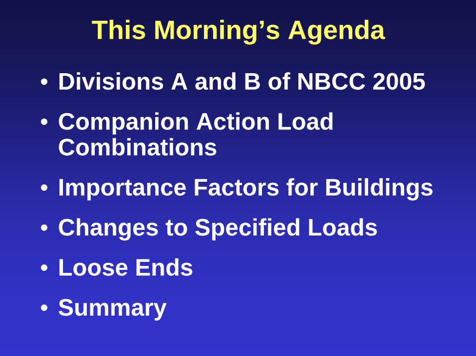
This Morning’s Agenda
• Divisions A and B of NBCC 2005• Companion Action Load
Combinations• Importance Factors for Buildings• Changes to Specified Loads• Loose Ends• Summary

NBCC 2005 is Objective-based
Division A (new!)• 4 objective categories• 46 functional statements
Division B (familiar)• “Acceptable solutions”• transition mechanism

Code of Hammurabi
Photo by C. R. Scollard

Not all that different..
• “a builder... [shall receive] ... 2 shekels of silver for every SAR of the house for his fee”
• This is equivalent to 72 days pay for a 44 m2 house
– (White Gergely & Sexsmith, 1972)
• say $40/s.f.

A Performance Code• “If a builder has made a house for a man
and has not made his work sound, and the house which he had built has fallen down and so caused the death of the householder, that builder shall be put to death.”
• “if it causes the death of the householder’s son, they shall put that builder’s son to death”
• “if the wall bulges, that builder shall put that wall into sound condition from his own silver”

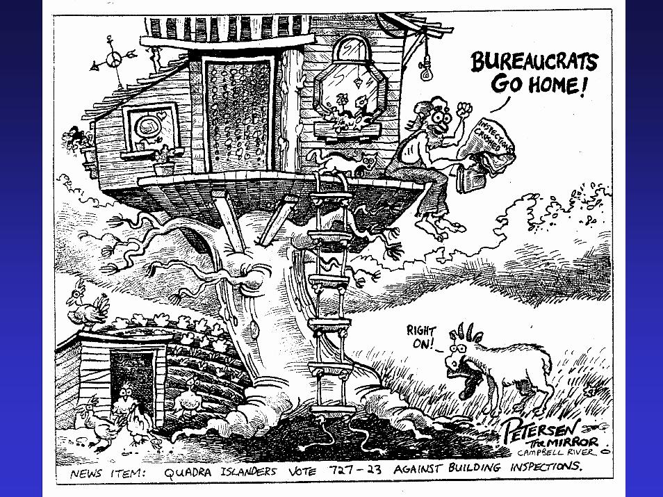
Canadian Code Development
Quebec Bridge: Canada’s longest cantilever
one footballfield

QuebecBridgeWorkers,1906

Wreckage1907

Finial as Grave Marker in St-RomualdCemetary
17 Americans58 Canadians(33 Caughnawaga
Iron Workers)

Drop-in Span Collapse11 September 1916
Death toll: 75 (1907) + 11 (1916) = 86
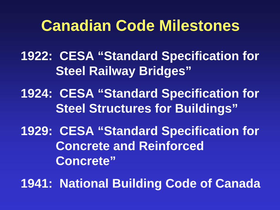
Canadian Code Milestones
1922: CESA “Standard Specification for Steel Railway Bridges”
1924: CESA “Standard Specification for Steel Structures for Buildings”
1929: CESA “Standard Specification for Concrete and Reinforced Concrete”
1941: National Building Code of Canada

1974: Limit States DesignKey Players
• D. J. L. Kennedy• J. G. MacGregor• D. E. Allen
Others
• A. G. Davenport• N. C. Lind• D. A. Taylor

Safety Objectives in NBCC 05
OS 1: Fire Safety
OS 2: Structural Safety
OS 3: Safety in Use
OS 4: Resistance to Unwanted Entry
OS 5: Safety at Construction and Demolition Sites

Structural Safety Objective
“to limit the probability that a person in or adjacent to the building will be exposed to an unacceptable risk of injury due to structural failure”

Structural Safety Sub-objectivesPrevent:
• loads exceeding capacity of building element or supporting medium
• Damage/deterioration of elements
• Vibration or deflection of elements
• Instability of building or part of building
• Collapse of excavations

Four Functional Statements
F20: To support and withstand expected loads and forces
F21: To limit or accommodate dimensional change
F22: To limit movement under expected loads and forces
F23: To maintain equipment in place during structural movement

Why this change?
“Codes freeze technology”- Prof. Paul Gavreau, U of T
Shortcoming of Division ADesigner must define, for a particular structure constructed using particular materials, “unacceptable risk”.

Hence Division B “Acceptable Solutions”
• Designs in conformance with the prescriptive requirements of Division B are deemed to have met the Objectives of Division A.
• Division B still represents “the minimum a designer is legally allowed to get away with”.

Questions?Questions?
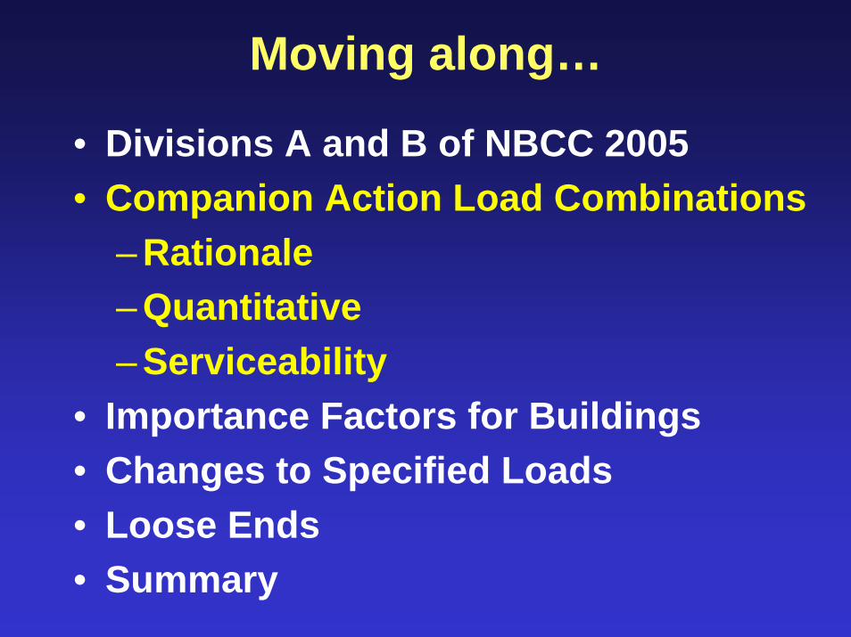
Moving along…
• Divisions A and B of NBCC 2005• Companion Action Load Combinations
– Rationale– Quantitative– Serviceability
• Importance Factors for Buildings• Changes to Specified Loads• Loose Ends• Summary

NBCC 1995 Format
φR > αD D + ψ γ {αL L + αQ Q + αT T}
where ψ = load combination factor
• NBCC 1995 load combinations:1.25 D + 1.5 L1.25 D + 1.5 Q (wind)1.25 D + 0.7 {1.5 L + 1.5 Q (wind)}
= 1.25 D + 1.05 L + 1.05 Q (wind)

Time History of Loading
time
Load
DeadRenovation
SustainedLive
Snow
TransientLive/Wind
Maximum Load,for Design
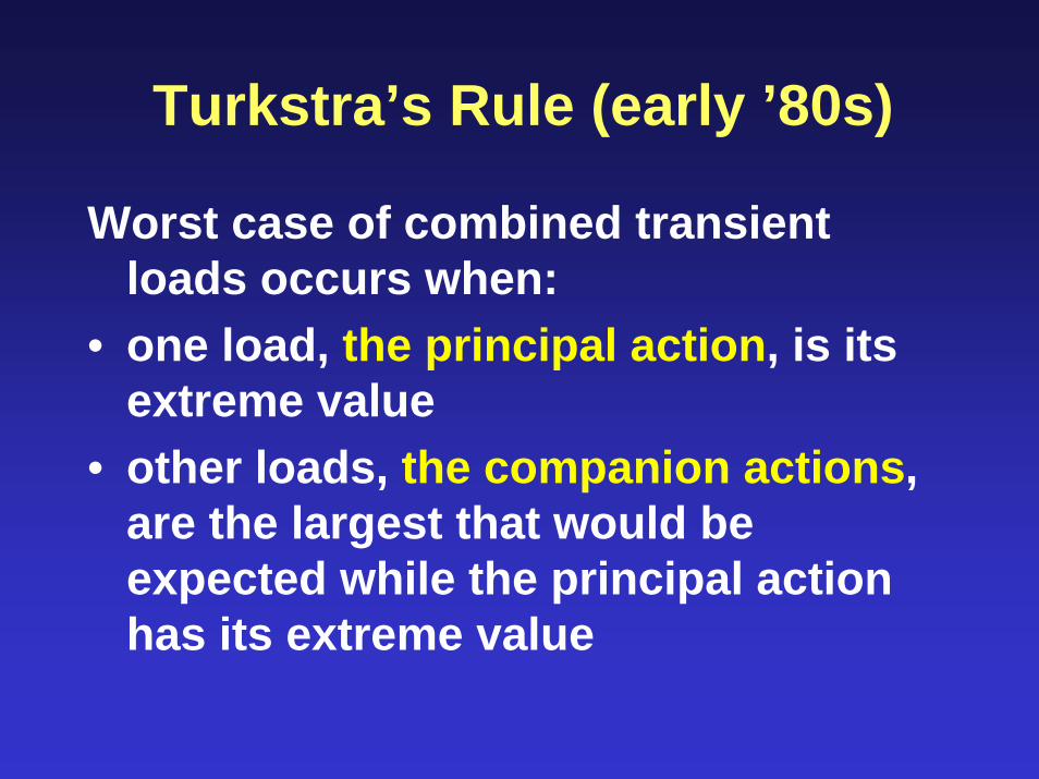
Turkstra’s Rule (early ’80s)
Worst case of combined transient loads occurs when:
• one load, the principal action, is its extreme value
• other loads, the companion actions, are the largest that would be expected while the principal action has its extreme value

Companion Action Format
φR > αD D + αi Si + Σ αik Sk , i ≠ k
where Si = principal actionSk = companion actions
Typical Load Combinations:1.25 D + 1.5 L + 0.5 W (wind)1.25 D + 1.5 W (wind) + 0.5 L
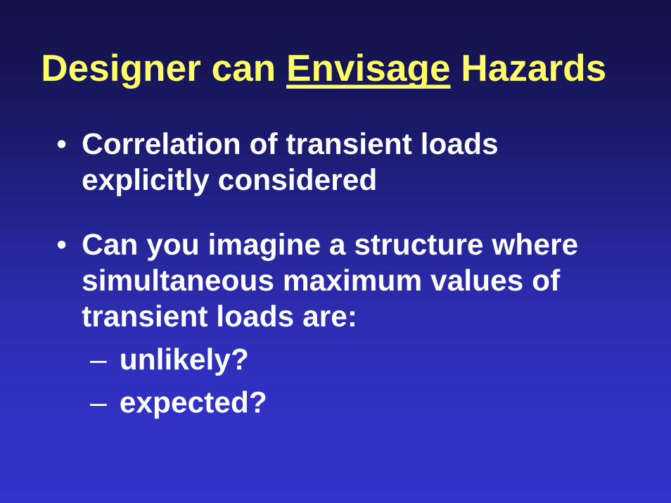
Designer can Envisage Hazards
• Correlation of transient loads explicitly considered
• Can you imagine a structure where simultaneous maximum values of transient loads are:– unlikely?– expected?

Confederation Bridge: Wind + Live

Confederation Bridge: Wind + Ice

1995 NBCC Reliability Indices
0
1
2
3
4
0 1 2 3 4 5Nominal variable load/nominal dead load
Rel
iabi
lity
inde
x (5
0-ye
ar)
D + W
D + L
D + S
• reliability for snow load deficient?

2000/2001 Failures: Sarnia Mall
Source: Globe and Mail 09 December 2000
Collapse

Snow Finds Weaknesses
Top Chord
SupportBeam
EndDiagonal

Huge “Secondary” Bending
Actual load ~specified load

NBCC 2005 Calibration Process1. Reliability indices for 1995 NBCC
2. Preliminary load combinations for 50-yr, 500-yr loads by Bartlett, Hong & Zhou
• review by Part 4 Task Group on Snow & Wind Loads
• review by Part 4 Standing Committee
3. Revised load combinations, 50-yr loads• review by Task Group and Part 4 cttee• public review

Calibration: Alberta Farmer Weighs Pig (MacGregor)
Step 3:Guess weight of rocks
Step 1:Put pig on plank
Step 2:Add rocksuntil plank level

2005 NBCC Combinations1.4 D1.25 D + 1.5 L + (0.4 W or 0.5 S)1.25 D + 1.4 W + (0.5 L or 0.5 S)1.25 D + 1.5 S + (0.5 L or 0.4 W)0.9 D + (1.5 L or 1.4 W or 1.5 S)
Add to all combinations:P = prestressH = horizontal earth pressuresT = restrained deformations (safety)

Impact: Single Transient Load
0.98
1.00
1.02
1.04
1.06
1.08
1.10
0 1 2 3 4 5
Pro
pose
d/N
BC
C 1
995
D+W
D+S
D+L
Transient-to-dead load ratio

Impact: D+L+S
0.7
0.8
0.9
1.0
1.1
1.2
0 1 2 3 4 5
Live-to-dead load ratio, L/D
Prop
osed
/199
5 N
BC
C
S/D = 0.250.5
1.0
2.0
4.0

Impact: D+L+W
0.7
0.8
0.9
1.0
1.1
1.2
0 1 2 3 4 5
Live-to-dead load ratio, L/D
Prop
osed
/199
5 N
BC
C
W/D = 4.0
2.01.00.25 0.5
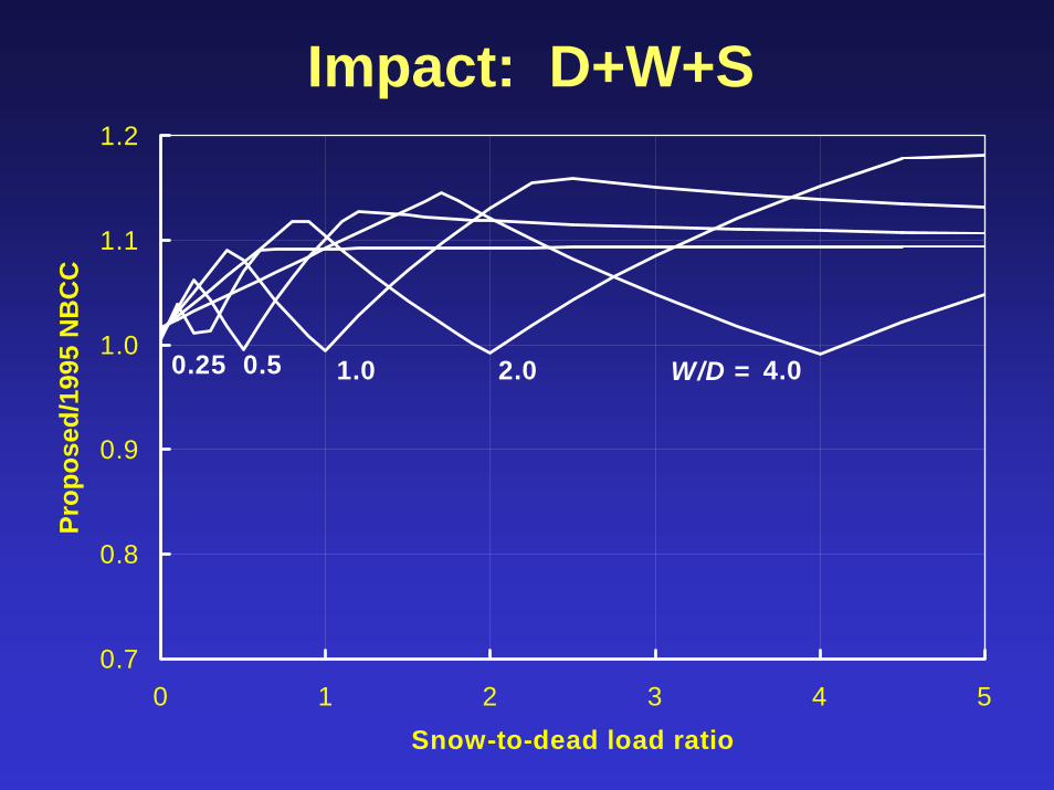
Impact: D+W+S
0.7
0.8
0.9
1.0
1.1
1.2
0 1 2 3 4 5Snow-to-dead load ratio
Prop
osed
/199
5 N
BC
C
W/D = 4.02.01.00.50.25

Serviceability Limit States• Intention is not to greatly change
serviceability design criteria.
• Consequence: specified snow load increases but for SLS check apply a SLS load factor of 0.9.
• Simplification: eliminate 1-in-10 yr specified wind load for SLS check but apply a SLS load factor of 0.75 to the specified (1-in-50 yr) wind load.

Table A-4 in Commentary A:
Limit States: Vibration serviceabilityOperation of moving equipmentDamage to non-structural comp.Damage to structural components
“Loads & Load Combinations for Serviceability”
Give:• Structural parameters to consider (stresses,
accelerations, crack widths, deflections)• Loads + load combinations• References

Table A-5 in Commentary A
Differential D + H + αLL + αSSSettlement
Long Term D + H + TP + P + αLL + αSSDeflection
Short Term (L + αSS) or (S + αLL)Deflection or W or E
“Load Combinations for Deflection Limit States”

Drainage
Waterrunsdownsurface
Waterdripsawayfromsurface

Questions?
• Far SideG. Larsen

Moving along…• Divisions A and B of NBCC 2005
• Companion Action Load Combinations
• Importance Factors for Buildings
• Changes to Specified Loads
• Loose Ends
• Summary

Table 4.1.2.1 “Importance Categories for Buildings”
Low: low direct or indirect hazard to human life.
Normal: the kitchen-sink category.
High: likely to be used as post-disaster shelters or contain hazardous substances.
Post-Disaster: essential to the provision of services after a disaster.

Importance Factors for S, W
Importance Ultimate Serviceability Category (Snow or Wind) Snow Wind
Low 0.8 0.9 0.75
Normal 1.0
High 1.15
Post Disaster 1.25 0.9 0.75

Questions?
Moving along…
• Divisions A and B of NBCC 2005• Companion Action Load Combinations• Importance Factors for Buildings• Changes to Specified Loads
– Uncouple L from S– 50 year return periods for W, S
• Loose Ends• Summary

Uncoupling Snow & Live
• Logical consequence of considering Live and Snow as independent.
• Similar format adopted in ASCE-7 based on load combinations derived in 1980.
• Consequence: Members resisting low D, high L (use + occupancy), high S require less resistance.

Is there a structure down there?
Clearing Trans Canada Highwayin Newfoundland(G. Jin, photo)


Live Loads on Roofs• Table 4.1.5.3 specifies 1.0 kPa
• Table 4.1.5.10 specifies 1.3 kNCommentary G “ Snow Loads”
paragraph 51 states:“These are use and occupancy loads, intended to provide for maintenance loadings, workmen, and so forth.”“They are not reduced as a function of area or roof slope”

Return Period for Environmental Loads
• NBCC 1995 specified:– 30 years for specified Snow, Wind– 10 years for Wind for deflections– 100 years for wind on Important
Structures• Use 50 year or 500 year return
periods (only) for 2005 NBCC?• Ratio n-yr/30-yr depends coefficient
of variation of annual maximum load

Wind Speed Data
0.00
0.10
0.20
0.30
0.40
0 20 40 60 80Longitude Difference (deg) from Alaska/Yukon Boundary
CO
V o
f Max
imum
Ann
ual W
ind
Velo
city
all data
>10 yrs data

Specified Load Return Period
0
0.5
1
1.5
2
0.00 0.05 0.10 0.15 0.20 0.25 0.30COV of Maximum Annual Wind Velocity
n-ye
ar p
ress
ure
/ 30-
year
pre
ssur
e
90% of values in this range
mean1-in-10
1-in-501-in-100
1-in-500

50-yr Wind & Snow Specified• typically ~10% greater than 30-yr
values
• snow load factor initially 1.7, implies a 25% increase in factored load, deemed too big.
• factored wind load unchanged, factored snow slightly greater
• reduce for SLS checks

Questions?
Far SideG. Larson

Moving along…• Divisions A and B of NBCC 2005
• Companion Action Load Combinations
• Importance Factors for Buildings
• Changes to Specified Loads
• Loose Ends– Dead load factors– Rain and ponding– Other examples
• Summary
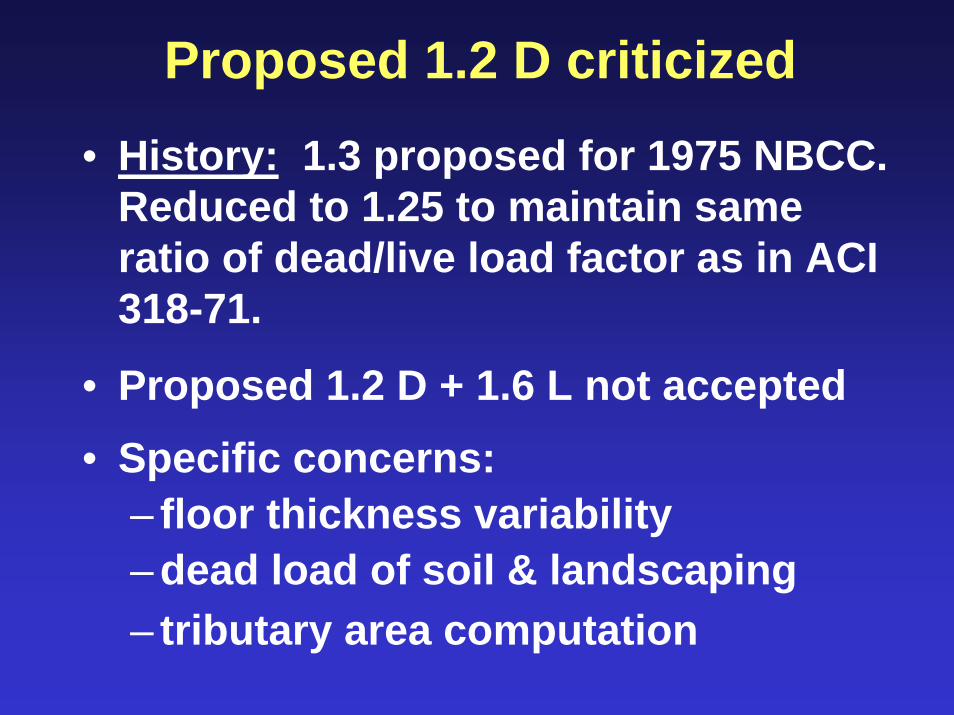
Proposed 1.2 D criticized• History: 1.3 proposed for 1975 NBCC.
Reduced to 1.25 to maintain same ratio of dead/live load factor as in ACI 318-71.
• Proposed 1.2 D + 1.6 L not accepted• Specific concerns:
– floor thickness variability– dead load of soil & landscaping– tributary area computation
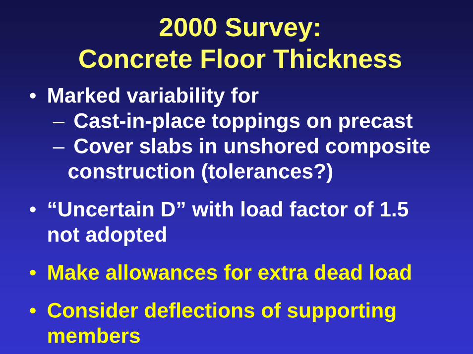
2000 Survey:Concrete Floor Thickness
• Marked variability for– Cast-in-place toppings on precast– Cover slabs in unshored composite
construction (tolerances?)
• “Uncertain D” with load factor of 1.5 not adopted
• Make allowances for extra dead load
• Consider deflections of supporting members

Tributary Areas in NBCC
Commentary Fig F-1:lines of zero shearhalfway betweencolumn lines
a (typ)0.5a0.55a
0.55b0.5b
• Para 6: “For continuous construction, structural analysis is required to find the lines of zero shear.”
• Safe for corners• Unsafe for 1st
interior columns

Rain Loads and Ponding• Flat roofs deflect, intensifying load in
worst place
• Essential design consideration for Calgary and southern Alberta
• NBCC Commentary H gives guidance– One-day rain load? – Residual stresses?– Multiple-span cases?
• Western M.E.Sc. thesis by Praught

Regions where 1-day rain exceeds snow load on flat roof
Tofino(147%)
Calgary(103%)
Port Hardy (131%)
Leamington (107%)Ucluelet(132%)

1-d rain and 24-hr rain• 1-d rain recorded 12:00 to 12:00• 24-hr rain in any 24-hr period
RainIntensity
Time
24-hr captures whole storm
1-day rain does not
• 24-hr rain/1-d rain ~ 1.23

Regions where 24-hour rain exceeds snow load
• Similar to Nixon’s (1979) “Ponding Map of Canada”
Ucluelet/Tolfino
Port Hardy
Leamington
Calgary
Whitehorse
Edmonton
VancouverVictoria
WinnipegFredericton
St
Yellowknife
Halifax
Iqaluit
Toronto
Charlottetown
Quebec
MontrealOttawa
Regina
Whitehorse

NBCC ignores residual stresses
Underestimates ponding deflections
Moment
Curvature
InitialEI
SecantEI at given M

Animation by Schouten Engineering Consultants, NL

Stepwise Analysis
1. Load joists
2. Calculate joist deflections, reactions
3. Apply reactions to beams
4. Calculate beam moments, deflections
5. Calculate total deflected shape
6. Do deflections converge?NO: recompute load and repeat analysisYES: stop, check capacities not exceeded

Gerber Beam Example Calculation
• Joists at 1.5m span 10.5m between beams
• W530x66 cantilever/anchor beam
• W460x52 drop-in beam
• Design for Calgary snow load, check for 1-day (not 24-hr, not factored) rain

Deflected shape after 1st iteration
JoistDeflection
Beam Deflection

Beam MomentsFinal (after 6th iteration)
Initial C symL
+26%
-20%
-26%
Volume of water on drop-in & cantilever spans reduces 46%

Deflections
C sym
Initial
Final
L

Questions?

David’s Questions
1. Composite prestressed concrete members will have stress limits based on dead, live and environmental loads. In the past I have used working stress load combinations to verify the stresses. How is this handled now?
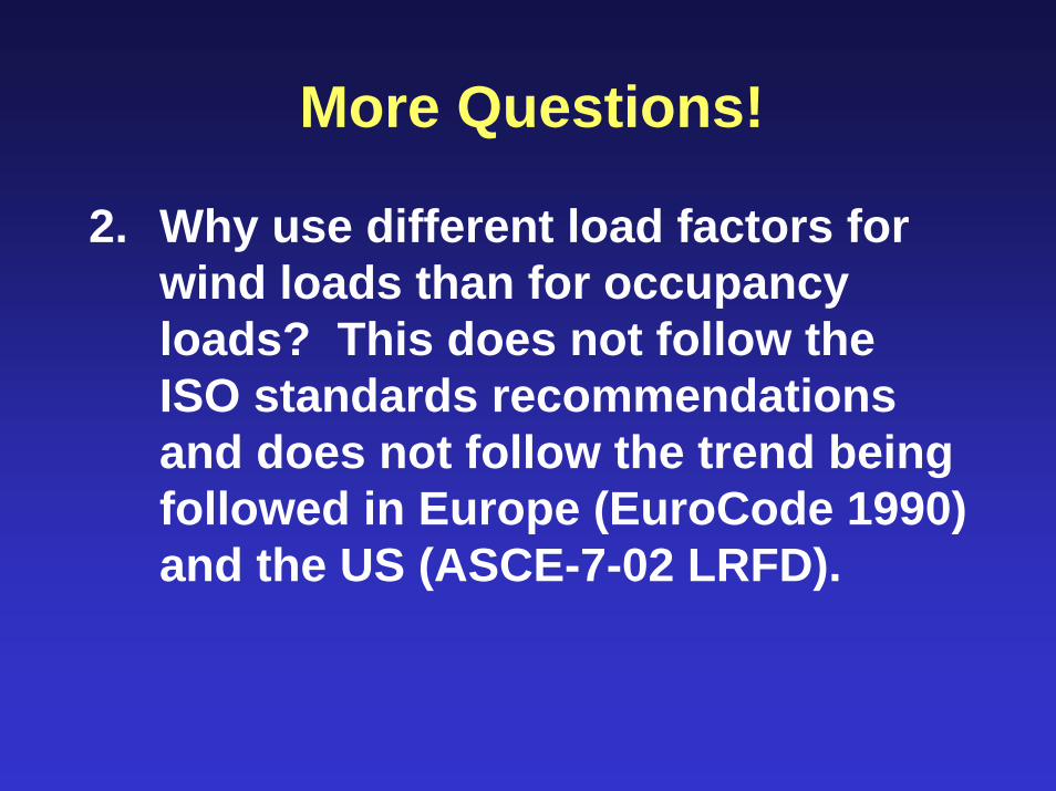
More Questions!
2. Why use different load factors for wind loads than for occupancy loads? This does not follow the ISO standards recommendations and does not follow the trend being followed in Europe (EuroCode 1990) and the US (ASCE-7-02 LRFD).

More Questions!
3. In the US, ASCE-7-05 uses a return period of 50 years but the Cb set at 0.70 versus 0.80 in the National Building Code of Canada. Why are we increasing the snow load relative to the US?

A Loaded Question?4. What loads are temporary
structures to be designed for in the new building code? Are the structures to be designed for the same likelihood of failure in an annual period or are they to be designed for the same likelihood of failure over the service life of the structure?

Questions?

Summary
1. Companion action load combination format proposed for NBCC 2005:
• more realistic representation• permits logical decisions for unusual
cases• little difference for many members• consistent with other international
standards (ACI 318, AISC LRFD, etc.)
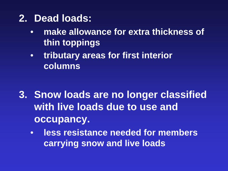
2. Dead loads:• make allowance for extra thickness of
thin toppings• tributary areas for first interior
columns
3. Snow loads are no longer classified with live loads due to use and occupancy.
• less resistance needed for members carrying snow and live loads
4. Only 50-year environmental loads specified:
• increases specified loads by ~ 10%• additional increases for important and
post-disaster buildings• load factors less than 1.0 reduce
specified loads for serviceability checks.
5. New load combinations give similar demands to NBCC 1995:
• less demand due to snow & live loads• more demand due to snow only

6. Watch out for ponding of rainwater on flat roofs:
• 24-hr rain ~1.23 x 1-day rain• residual stresses reduce stiffness• multi-span members can share
water between spans
7. The National Building Code remains a minimum standard:
• consult with owner to confirm what really is necessary

“More than ever before, the challenge to the profession is to develop designers who have sufficient intuition to stand up to, and reject or modify, the results of a computer-aided analysis or design.”--- J. G. MacGregor,
Professor Emeritus, University of Alberta

• Two papers by Bartlett, Hong & Zhou, Canadian Journal of Civil Engineering, April 2003.
• Paper by Praught & Bartlett in 2005 CSCE Annual Conference, Toronto.
• More information: [email protected]
Additional References

Acknowledgements• National Research Council of Canada• National Sciences & Engineering
Research Council of Canada• NBC Part 4 Task Group on Snow and
Wind Loads (D. E. Allen, Chair)• Canadian Meteorological Centre• Steel Structures Education
Foundation• J. G. MacGregor