the objective of this module is to introduce the concept
TRANSCRIPT

1
The objective of this module is to introduce the concept of VLANs (Virtual Local Area Networks).
VLANs are important to improve performance and security of IP networks. VLAs affects the form
that IP addresses are assigned to the network, as well as the form IP packets are routed.
Besides VLANs, this module will also address the concept of Spanning Trees, an important
feature of the switched Ethernet. The STP (Spanning Tree Protocol) can be combined with VLANs
to provide load balance and recovery through the use of redundant paths.
In order to facilitate the understanding of how Ethernet was expanded to support VLANs, this
module starts with a review on the standardization and the format of the Ethernet frames.

2
Initially developed as a low cost alternative for implementing small computer networks in the
early 70s, the Ethernet technology has consistently evolved in its almost 40 years of existence. The
initial design of Ethernet was developed by Robert Metcalfe, then a Xerox employee, during the
period 1970-1976.
The first proposed version was known as Ethernet I, and operates at 3 Mbit/s. Though still
incipient, this version was already based on the CSMA/CD (Carrier Sense Multiple Access with
Collision Detection) as a medium access control method.
In 1980, Xerox, Intel and Digital companies have teamed up to develop a “de facto” standard for
Ethernet in order to market it. The resulting standard was known as Ethernet II, and uses a frame
format called DIX (the initials of the three companies). The DIX format is used until today.
Curiously, during this period, Robert Metcalfe left Xerox and founded 3Com, which would
become a important vendor of Ethernet network adapters.
In 1985, Ethernet was standardized by ANSI/IEEE under the denomination IEEE 802.3. This
standardization has defined a new frame format called IEEE 802.3 LLC. There are some
differences between the IEEE and the DIX format, but both formats are supported and found in
modern Ethernet networks. In 1997, a review in the Ethernet specification, called IEEE 802.3x,
came to accept the DIX format also within the IEEE standard.
In 1998, an IEEE specification introduced a new field for the DIX and LLC frames. This new
field, known as Q Tag, has introduced the possibility of using the concepts of VLANs (Virtual

Local Area Networks) and priority with the Ethernet technology.
2

3
The IEEE 802.3 standard that defines the Ethernet is part of a family of broader standards called
IEEE 802. The IEEE 802 family includes old technologies like Ethernet (IEEE 802.3) and Token
Ring (IEEE 802.5). It also includes various recent technologies (especially wireless technologies),
as WiFi (IEEE 802.11), WiMax (IEEE 802.16) and technologies for PAN (Personal Area
Network), as the IEEE 802.15 (BlueTooth and ZigBee).
IEEE 802 technologies correspond to the Data-Link (2) Physical (1) layers of the OSI model. For
example, in the case of Ethernet, the Physical Layer defines cable types (e.g., UTP or optical
fiber), the transmission rate and the physical representation (electrical or optical) of bits.
The IEEE 802.2 also defines a subdivision of the Data Link layer into two sub-layers: Logical
Link Control (LLC) and Medium Access Control (MAC).
Note in the figure that sub-layer LLC is common to the various transmission technologies and the
MAC sub-layer is specific to each technology. The LLC sub-layer for all technologies is defined
by a single standard called IEEE 802.2. The LLC sub-layer does not exist in the Etherenet II. In
fact, the existence of this sub-layer is the mainy difference between the IEEE 802.3 and Ethernet
II.

4
Ethernet II and IEEE 802.3 have different frame formats, as illustrated in the figure. The Ethernet
frames are also known as DIXv2. As previously stated, only IEEE 802.3 frames can encapsulate
the LLC PDU. The other difference between the frames formats is the Type Field (DIXv2) that is
replaced by a Length field in the IEEE 802.3 format.
The LLC header is placed at the beginning of the Ethernet frame's payload. The LCC headers
introduces a new level of addressing, by use of SAP (Service Access Point) addresses. It allows to
address multiple services on a single MAC address, similarly to the TCP/UDP ports on the IP. The
use of LLC is common in low level network protocols used by Switches, such as the STP
(Spanning Tree Protocols) (seen in the sequence of this module).
Ethernet frames define a minimum and a maximum payload size. The minimum size is required to
ensure that a transmitting station has enough time to detect a collision before the end of a frame.
The maximum payload size is called "maximum transportable unit (MTU). In the case of Ethernet,
the MTU is 1500 bytes. The protocol of the network layer (i.e., the IP) needs to ensure that no IP
packet longer than 1500 bytes is sent to Ethernet layer. This can be achieved by a process called IP
fragmentation.
To allow an Ethernet network adaptor to distinguish correctly the two frame formats the following
convention is adopted to the values of the Length/Type field:
• Values up to 1500: the frames is IEEE 802.3, and the value is the payload length.

• Values higher than 1500: the frame is Ethernet II, and the value is a protocol type code.
Note that protocols transported by Ethernet are identified by codes numbers greater than
1500. For example: IP = 2048 (0x800), ARP = 2053 (0x806).
Usually, the Preamble field does not appear in the high level representation of Ethernet
frames. Its purpose is to permit the network adaptor to determine the beginning of a new
frame.
4

5
There are two types of MAC addresses: Locally Administered (Local) and Universal. Local
addresses are set freely by the network administrator, but they must follow the convention that the
value of the second most significant bit of the address (see b7 in the figure) must be equal to 1.
The Universal addresses are globally unique because OUIs (Organizational Unique Identifier) are
assigned by the IEEE to computer network vendors. For example, Xerox received the OUI range
from 00-00-00 to 00-00-09.
Similar to IP addresses, the MAC addresses can also be unicast or group addresses (broadcast or
multicast). The scope of the address is determined by the bit b8, as indicated in the figure.
Not all universal addresses are used to identify network adapters. Some OUIs have been assigned
to be used by standard data-link protocols, such as STP (Spanning Tree Protocols). The OUI
reserved to the data-link protocols is x-80-C2. This OUI includes unicast addresses (when X = 0)
and group addresses (when X = 1).
In some cases, a multicast frame received by a switch must be interpreted locally only and not be
re-transmitted to other switches in the network. In other cases, the multicast frame must be re-
transmitted. This control is done by dividing the address block reserved to data-link protocols into
2 sub-groups called: filtered (do not propagate multicast) and standard (propagate multicast).
The filter mode addresses range from 01-80-C2-00-00-00 to 01-80-C2-00-00-0F. The standard
mode addresses range from 01-80-C2-00-00-10 to 01-80-C2-FF-FF-FF.

6
Cascaded switches cannot from a closed path (loops). Loops are problematic to switches due to the procedure used to fill the forwarding tables. Switches observe the source MAC address of incoming packets, to determine how to forward packets to these addresses. When a switch needs to send a frame to destination MAC address that is not in the forwarding table yet, it performs a broadcast.
For example, consider the scenario in Figure 1, which has no loop. After a certain operation period, switches achieve an stable state, where the position of all MAC addresses is known. Suppose the “E” computer sends a packet to the “F” computer that is not yet known by the switch.
Switch 3 will send the packet in broadcast to all its ports, including the port used to cascade to switch 1. Switch 1 also sends the packet to all its ports, and the packet eventually arrives to switch 2. Therefore, the packet is received by all computers on the three switches, but only computer F that has the destination MAC address will interpret the packet.
IP networks employ many broadcast based protocols, such as ARP. Broadcast packets are treated by the switch as unknown MAC addresses.

7
Consider now the scenario 2, where a loop was formed by inserting a new connection between
switches 2 and 3. Let's consider again the case when the “E” computer sends a frame to the “F”
computer, still unknown in the network. To illustrate the effect of loop, let's follow the frame
initially sent through the port 1 in switch 3. Upon receiving the frame, switch 1 assumes that the
“E” address is accessible using the port 1. As it does not know the location of F, it forwards the
frame to all its other ports.
After receiving a frame, switch 2 also considers the “E” address accessible using the port 1. Again,
as the switch 2 doesn't know the location of F, it will forward the frame to all its ports, making the
frame return to switch 3, but now through the port 3. Because is received in a different port in
switch 3, it is considered a new frame, and send again in broadcast repeating the cycle.
The same process happens in the reverse path, as the frame is also forwarded through the port 4 of
switch 3. The loop causes the position of the computer “E” to be assigned to multiple switch ports,
causing additional loops when computer “E” is addressed by other computer.
As the frames circulates endlessly by the closed loop, the traffic in all switches ports increases
dramatically, leading to a complete network congestion.

8
Switches utilize a protocol to automatically detect and eliminate closed loops. This protocol is
called "Spanning Tree Protocol - STP". The STP is a Layer 2 protocol, and it should run on all
switches in the network. The principle of the STP is that only one active can exist between two
stations in the network. If more than one path is discovered, certain switch ports are blocked by
software to eliminate the loop.
When the STP is used in a switched network, the resulting topology is always a tree, which by
definition has no loops, and justifies the name of the protocol.
The strategy is to elect one of the switches of the network as root, and build a tree determining the
shortest path between each one of the other switches and the root.
Messages generated by STP are called BPDU (Bridge Protocol Data Unit). These messages use
multicast MAC addresses in the range 0x0180C20000000 to 0x0180C20000010. This range
corresponds to the OUI reserved to data-link protocols in filtered mode.
If STP is active, the received BPDU are interpreted locally by the switch and are not forwarded. If
STP is inactive, BPDU frames are sent to the other switches as if they were unknown multicast
addresses.
STP operates continuously in order to reflect changes in the network topology.

9
In STP networks, all switches have an identifier (ID) consisting of 8 bytes: 2 bytes of priority
(configurable) and 6 bytes of a MAC universal address (assigned by the manufacturer). This
identifier is called Bridge ID. In addition to its own ID, each switch needs to know the ID of the
root switch in the network. This is done through an election process, described in the sequence of
this module.
All BPDU messages sent by a switch carries its own ID (Bridge ID field), the ID of the root of the
network (Root ID field) and the cost of the best known path from this switch to the root (Root Path
cost field). These three fields are the most important to understand the operation of STP. The
format of the BPDU message fields are summarized below:
Protocol Identifier: 0 (STP)
Version: 0 (ST)
Message Type: 0 (Configuration)
Flags: Topology change (TC), Topology change acknowledgment (TCA)
Root ID: 2-byte Priority + 6-byte MAC of the Bridge
Root Path cost: 4-Bytes indicating the cost of the path from the bridge to the root.
Bridge ID: 2-byte Priority + 6-byte MAC of the Bridge
Port ID: 2 Bytes (used to select the port to be blocked in case of loop)
Message Age: Elapsed time passed since the message was sent by the Root Maximum Age: Age

from which the message should be ignored
Hello Time: Interval between messages sent by the root
Forward Delay: Time that the bridge should wait before changing state in case of change of
topology.
9

10
The first important event in a network with STP is to elect the Root (root). Initially, all switches
are considered Root. They all send, through all its ports, BPDU messages with identical Root ID
and Bridge ID and a Path Cost equal to “0”.
When a switch receives a message with an Root ID lower than its root, it accepts the new switch
as root. If the Root ID in the incoming BPDU message is higher that its own, it is ignored. As we
have seen, the Bridge ID consists of two numbers: priority + MAC address. By default, the priority
of all the switches is 32768 and the election of the Root is made by MAC.
As the MAC is determined by the manufacturer, it may happen that the root selection
made automatically is not the most suitable for the network (for example, a peripheral or low-
capacity switch may end up being selected as root). To prevent this, the administrator must reduce
the priority of the switch that he wants to be made as Root.

11
The spanning tree is defined from BPDU messages sent by the Root. For example, switch 1 (Root)
sends BPDU messages to switches 2 and 3, stating that it is the Root and the cost from it to the
root is 0. Internally, Switches 2 and 3 assigns a new cost to root offers that depends on the
transmission rate of the port that received the BPDU messages. The Cisco default costs assigned to
Gigabit (1 Gbps) and Fast Ethernet (100 Mbps) ports area respectively 4 and 19.
Switch 2 propagates the message received from the Root to the switch 4, indicating its own ID in
the Bridge-ID field and assigning path cost equal to 4. Switch 3 also propagates a BPDU message
to switch 3 and indicates path cost equal to 4.
Thus, the switch 4 receives two path offers to the root. According to the STP, only one can be
accepted. That means that a switch can have only one RP port. Internally, switch 4 calculates that
the cost to the root using the switch 2 path is 8, and using the switch 3 path is 23. The switch 4
accepts the switch 2 offer (i.e., lower path cost) and blocks the port that connects to the switch 3,
thereby preventing the occurrence of the loop.
Switch 3, however, will keep sending BPDU messages, that will be ignored.

12
Many manufacturers define a default configuration that allows the switch to start in an acceptable
mode of operation, even if the administrator does not change any of the parameters of the switch.
The table above shows the default setting for Cisco switches, model 2950. STP is enabled by
default, but only for VLAN 1. As we shall see, the operation of the STP is affected by the use of
VLANs (Virtual Local Area Networks) in Ethernet switches. There are some variations of STP that
modifies how the protocol interacts with VLANs. For example, the acronym PVST (Per-VLAN
Spanning Tree) is a mechanism that permits to use alternate paths between switches for the
purpose of load balancing, instead of simply blocking all ports that cause loops .
Also, in the table, both switch and ports have a default priority. As explained, the priority of the
switch is used in the election of the Root. The priority of the port is used when the switch receives
multiple path offers from different ports, but all with the same cost. In this case, the port with the
lowest priority is selected, and the others are blocked.
The table also shows the suggestion of Cisco for the cost of the doors, the relative speeds
available. Note that the suggested table, it is more advantageous to choose a path that goes through
three switches with ports of 1000Mbps (4 links cost = 16) than a direct path to the root, but using a
100Mbps port (1 link cost = 19 ). However, if the path to Gigabit-Ethernet ports is formed by four
switches (5 enalces cost = 20), then it is best to choose the direct path of Fast Ethernet.

13
As the transmission rate of the Ethernet technology began to increase and the use of switches
became more common, new mechanisms to improve the scalability and security of Ethernet
networks were created.
VLANs emerged in 1998 and quickly became an essential tool for increasing the performance and
security of Ethernet networks. To understand the purpose of the VLAN, let´s recall how a switch
operates. We know that after an initial learning process, the switch forwards frames only to the
ports that are mapped to the destination MAC of the frames. This is true for most cases, except
when the destination MAC address is unknown or is a broadcast ("FF-FF-FF-FF-FF-FF“). When a
frame with a broadcast destination is received by the switch, it will be propagated to all other
ports, including the ports used to cascade to other switches.
Unfortunately, the presence of broadcast frames are quite common in IP networks. For example,
the ARP (Address Resolution Protocol) used to resolve IP addresses into MAC addresses, always
send broadcast messages. Many other protocols, such as DHCP, also do that. As a result, a big
Ethernet network formed by many cascaded switches will experience a high level o broadcast,
greatly reducing the network performance.

14
VLANs solve the problem of network congestion by introducing a mechanism that group the
switch ports into isolated broadcast domains. To illustrate this principle, consider the switch in the
figure.
According to the concept of VLANs, one can assign a TAG (a number between 1 and 4096) to
each port of the switch. Ports that have the same VLAN TAG constitute a isolated broadcast
domain.
For example, the switch in the figure was split into two VLANs. VLAN 1 comprises ports 1 to 3
and VLAN 2 includes the ports 4 to 6.
If computer A sends a frame in broadcast, it will be propagated only to ports in VLAN 1. If the
computer D sends a broadcast frame, it will be propagated only to ports in VLAN 2.

15
In order to support the concept of VLANs, IEEE initially developed the following standards: IEEE
802.1Q and IEEE 802.1p.
The IEEE 802.1Q standard defines the operation of VLANs, and defines an extension in format of
the Ethernet frames, adding four bytes to the header, as shown in the figure. The IEEE 802.1Q
header extension defines the following fields:
- PRIO: Priority field with three bits (8 levels of priority)
- CFI: Canonical Format Indicator (always 0 for Ethernet frames)
- VLAN ID: The identifier number, ranging from 1 to 4096
- TYPE: The protocol type transported by the frame
In order to allow a network adaptor to interpret frames with or without the VLAN extension, the
protocol type 0x8100 was defined to identify frames in the IEEE 802.1Q format. The protocol type
of the packet transported in the payload of the frame (usually, 0x8000 for IP packets) is indicated
in Type field of the VLAN Tag.
Note that due to the additional 4 bytes of the VLAN Tag, the MTU (Maximum Unit Transportable
Unit) of Ethernet frames was reduced from 1500 to 1496 bytes.

The PRIO field also defines the concept of class of service (Class of Service - COS) for
Ethernet frames. This field permit to prioritize frames carrying real-time traffic type (that do
not support high delay) over other types of traffic which can be delivered with a lower
priority. Service classes and the corresponding values of the PRIO fields are defined in the
IEEE 802.1p standard.
The CFI bit indicates that the VLAN extension could be used in other IEEE 802 protocols,
such as Token Ring.
15

16
The redefinition of broadcast domains introduced by the use of VLANs also applies to cascaded
switches. The mechanism of VLANs is very flexible, and permits to organize computers into
separate broadcast domains, regardless of their physical location.
The scenario in the figure consists of three interconnected switches, which are configured with two
VLANs. The computers A, B and C belong to the same VLAN even though they are connected to
different switches. If computer A sends a broadcast message, it will be propagated to other
switches, but only to the ports that also belong to VLAN 1. Computer D that is in the same switch
than A does not receive the broadcast. However, computers B and C connected in different
switches do.
Switch ports can operate in two different modes: access mode and trunk mode. A port in access
mode belongs to a single VLAN. This type of port is used to connect computers and operates with
frames in standard format, IEEE 802.3 or Ethernet II. Note that this format does not have VLAN
TAGs.
A port in trunk mode is used to connect two switches. A trunk port can belong to multiple VLANs,
and it only sends and receives frames with VLAN TAGs.

17
If a switch port configured in access mode receives a 802.1Q frame it discards. Only ports
configured as trunk are able to interpret frames with VLAN tagging.
The ports used to cascade switches must be configured in trunk mode. If a port is in trunk mode
and the other not, there will be no communication.
Some switches use a proprietary protocol that can automatically detect if a given port is connected
to a computer or another switch. If it detects that the port is connected to another switch, it
automatically configures the port in trunk mode.
To understand the differences between ports operating in access mode and trunk mode, consider
that computer A sends a frame to computer B. The frame sent by A has no VLAN TAG. Upon
entering in the switch 1, the frame receives a VLAN TAG (i.e., it becomes a IEEE 802.1Q frame)
and is propagated to the switch 2 through the trunk port.
Switch 2 receives the frame and determines to which port it must forward the frame based on both,
the destination MAC address and the VLAN TAG. As the destination port is in access mode, it
removes the VLAN TAG and deliver the frame in IEEE 802.3 or Ethernet II format to computer B.
A port trunk usually does not accept frames unmarked (except Native VLAN concept discussed
later in this handout). That were, if you connect a computer to a trunk port is likely he lose access

the network.
On some operating systems such as Linux, you can configure the network card to send
packets with VLAN tagging. In this case, it is necessary that the switch port to which the
computer is connected to function in trunk mode.
17

18
The division into VLANs affects how the allocation of IP addresses is done in the network. For all
purposes, the properties of a VLAN are the same as a LAN, i.e.:
A) Computers in the same VLAN must have the same network identifier
B) Each VLAN must have an unique network identifier
As previously emphasized, the VLAN mechanism allows the administrator to organize the
Ethernet network independently of how computers are physically connected. Observe in the figure
that computers A and D, despite being connected to the same switch, belong to different subnets.
And computers A and B, which are in different switches, belong to the same subnet.
Computers in different VLANs can not communicate directly. It is necessary to connect VLANs
using routers to permit the communication between computers belonging to different VLANs. This
is true even if you assign addresses from the same subnet to different VLANs.
This property permit to enforce security policies and give different level of access to resources to
the computers in the network. Consider a the scenario where an university has two networks:
academic and administrative. The academic network is available to teachers and students, and its
main purpose is to offer access to resources on the Internet. The administrative network, on the
other hand, provides access to internal systems such as payroll, accounting and billing. For
security reasons, it is not recommended that a computer in a laboratory has access to any internal

system in the University.
This can be controlled by using different VLANs for the two networks. By imposing that the
traffic between the VLANs must pass through a router, it is possible to control the traffic
between the VLANs by the use of a firewall.
18

19
Communication between computers in different VLANs is possible must be intermediated by
routers. There are several ways to connect the routers to switches. First, let´s consider a scenario
where routers without IEEE 802.1Q support are used.
Consider the example in the figure. The first switch has a computer on VLAN 1 (A) and other in
VLAN 2 (C). The second switch has a computer on VLAN 1 (B) and other in VLAN 3 (D). As
there are three VLANs on the network, a router must be used to connect VLAN 1 to VLAN 2 and
other router to connect VLAN 1 to VLAN 3.
To permit the communication between different VLANs, a router must have interfaces connected
to switch ports belonging to different VLANs. For example, router 1 has an interface on VLAN 1
and other on VLAN 2. Router 2 has an interface on VLAN 1 and other on VLAN 3.
The path followed by a packet sent by computer A (VLAN 1) to C (VLAN 2) is indicated in the
figure. The packet goes through router 1. In this process, the switch port that sends the packet to
router 1 removes the VLAN 1 TAG and the switch port that receives the packet from the router
inserts a new VLAN TAG corresponding to VLAN 2.
When computer A (VLAN 1) sends a packet to computer B (VLAN 1), the frame can be
transmitted through the trunk port without the help of a router.
When computer A (VLAN 1) sends a packet to computer D (VLAN 3), the frame is sent with

VLAN 1 TAG to router 2. The frame sent by router 2 receives a VLAN 3 TAG. Finally, the
frame received by D has the TAG removed by the switch port.
19
20
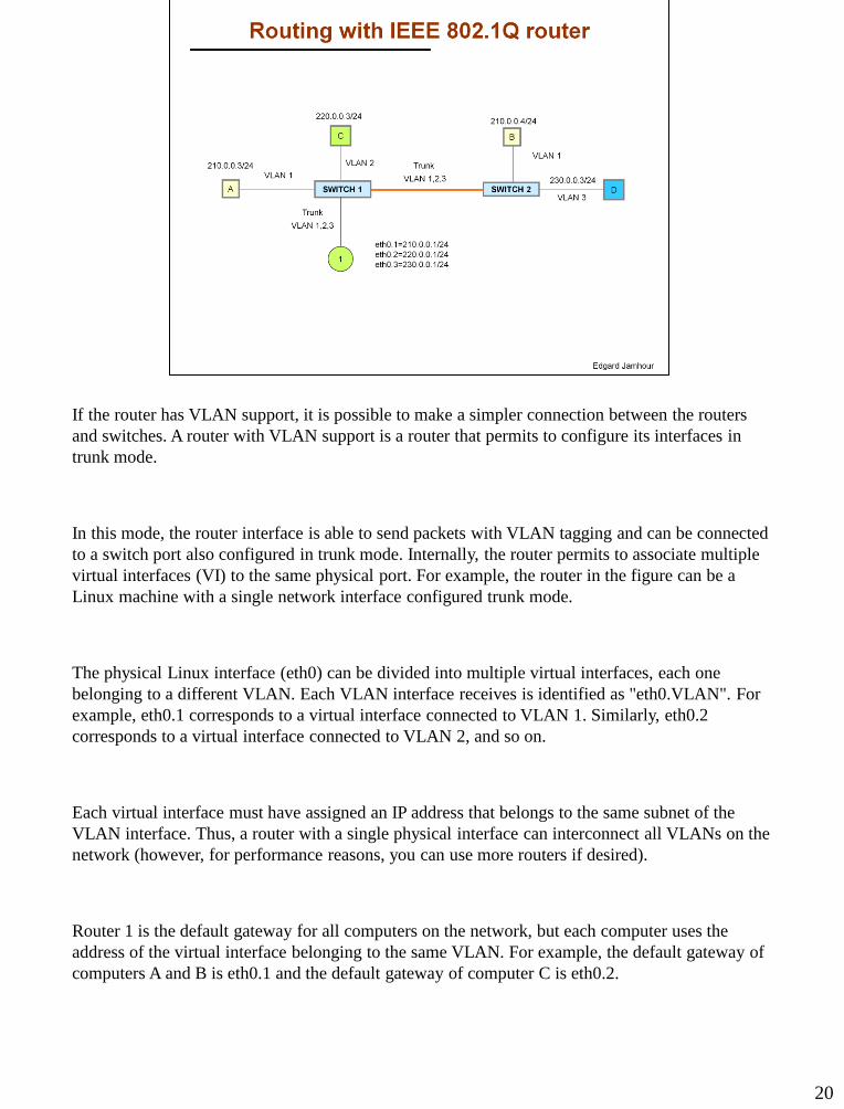
If the router has VLAN support, it is possible to make a simpler connection between the routers
and switches. A router with VLAN support is a router that permits to configure its interfaces in
trunk mode.
In this mode, the router interface is able to send packets with VLAN tagging and can be connected
to a switch port also configured in trunk mode. Internally, the router permits to associate multiple
virtual interfaces (VI) to the same physical port. For example, the router in the figure can be a
Linux machine with a single network interface configured trunk mode.
The physical Linux interface (eth0) can be divided into multiple virtual interfaces, each one
belonging to a different VLAN. Each VLAN interface receives is identified as "eth0.VLAN". For
example, eth0.1 corresponds to a virtual interface connected to VLAN 1. Similarly, eth0.2
corresponds to a virtual interface connected to VLAN 2, and so on.
Each virtual interface must have assigned an IP address that belongs to the same subnet of the
VLAN interface. Thus, a router with a single physical interface can interconnect all VLANs on the
network (however, for performance reasons, you can use more routers if desired).
Router 1 is the default gateway for all computers on the network, but each computer uses the
address of the virtual interface belonging to the same VLAN. For example, the default gateway of
computers A and B is eth0.1 and the default gateway of computer C is eth0.2.

21
The routing table of the router 1 determines to which virtual interfaces the packet must be
forwarded according to the destination network.
Consider the scenario where computer A (VLAN 1) sends a packet to the computer D (VLAN 3).
The packet sent by A arrives at the router with VLAN 1 TAG and it is received by the eth0.1
interface. The eth0.1 interface removes the TAG and forward the packet to the routing module.
The routing module decides that a packet addressed to the 221.0.0.0/24 subnet must be sent
through the eth0.3 interface.
The packet sent to eth0.3 is encapsulated in a frame with VLAN 3 TAG and routed to the switch 2
using the trunk port between the two switches. Switch 2 send the frame to computer D, connected
to a port in access mode. For this, it removes the VLAN TAG before delivering the frame to
computer D.
As shown in the figure, a router with IEEE 802.1Q support can also be used to connect the
network organized in VLANs to the Internet.

22
The third way to interconnect the VLANs is to use a Layer 3 switch, i.e., a switch with routing
capability.
A Layer 3 switch permit to create a virtual interface called SVI (Switch Virtual Interface) for each
existing VLAN. Each SVI behave as a physical interface, having an unique MAC address. The
network administrator should assign an IP address for each SVI, according to the subnet associated
with the VLAN of the interface. Computers use the SVI addresses as default gateways, also
according to the VLAN that they belong.
This principle is illustrated in the figure. Note that switch 1 is a Layer 3 switch, and switch 2 is a
Layer 2 switch with no routing functions. Computers belonging to VLAN 1 uses the IP address of
SVI1 as default gateway, those belonging to VLAN 2 use SVI2 and those belonging to VLAN 3
use SVI3.
The operation of a Layer 3 switch is similar to the operation of the router with trunk port,
previously described. For example, when computer A (VLAN 1) send a packet to the computer D
(VLAN 3), it uses SVI1 as default gateway. The virtual router receives the packet by the SVI1
interface, and determines that the packet must be sent through the SVI3 interface. A new frame
VLAN 3 TAG is then created and sent through the trunk port connecting to switch 2. The switch
removes the VLAN TAG and deliver the frame to computer D.
The SVI are not accessible externally. To connect the VLANs to the Internet, some switches offer
the ability to create router ports mapped on physical switch ports. Such ports may or may not be
mapped into VLANs. The figure also illustrates this concept.

23
Vamos agora analisar como seria o funcionamento do protocolo de Spanning Tree (STP) na
presença de VLANs. Para isso, considere o cenário mostrado na figura. Como a rede de switchs
apresenta um laço fechado, se considerarmos um protocolo de STP insensível a VLANs, um dos
enlaces entre os switches deveria ser eliminado. Por exemplo, na figura, suponha que todos os
enlaces possuem a mesma velocidade (100Mbps). Se o switch 1 for escolhido como root, então o
enlace entre os switches 2 e 3 será bloqueado.
Na prática, isso vai fazer com que os recursos da rede fiquem sub-utilizados, pois todas as vezes
que algum computador no switch 2 desejar se comunicar com o switch 3, ele será encaminhado
pelo root, quando seria mais eficiente utilizar o enlace direto entre os dois switches.
Felizmente, quando VLANs são utilizadas, existem variantes do STP que permitem utilizar todos
os enlaces disponíveis na rede de switches simultaneamente, sem correr o risco de criar laços
fechados.
O princípio utilizado por essas variantes do STP é vincular as portas trunk a VLANs específicas ao
invés de todas as VLANs. Dessa forma, o algoritmo STP poderá criar uma árvore de switches
independentes para cada switch.
Essa variantes do STP é denominada PVSTP (Per-VLAN Spanning Tree Protocol).

24
To simplify the presentation of the following examples, we will consider the following switch
model: the Cisco Catalyst, model 2950G, 24 Fast-Ethernet ports and 2 Gigabit-Ethernet ports.
Ports are identified by labels of type Slot/Port. The Slot is a conceptual module of the switch. The
simplest models have only one slot labeled “0”. A slot-Fast Ethernet port Fa0 is called. The
Gigabit Ethernet ports are called G1/0. Ports are identified by their position in the chassis,
numbered from left to right, as indicated in the figure.
Cisco switches can be configured by telnet. The Cisco IOS has a fairly simple configuration
syntax, which is imitated by some free software like Quagga. The sequence of basic commands to
associate a port to a VLAN in access mode is shown below:
enable
#enter the switch in configuration mode (password may be requested)
configure terminal
interface Fa0/2
switchport mode access
switchport access vlan 2
end

25
By default, each trunk port can be used for all VLANs on the switch. In the default configuration,
assuming that switch 1 is the root, the link between switches 2 and 3 would be blocked.
However, you can restrict the use of specific VLANs in trunk ports. This allows you to perform
traffic engineering and control through which links each type of traffic will go.
In the scenario shown in the figure, computers connected to the switches are in two Vlans (1 and
20). Computers are connected by Fast Ethernet ports, and switches are connected by Gigabit
Ethernet ports. In order to avoid blocking ports between the switches 2 and 3, the following
restrictions on traffic trunk ports were made:
• trunk ports between the switches 1 and 2: carries ALL VLANs
• trunk ports between the switches 1 and 3: carries only VLAN 1
• trunk ports between switches 2 and 3: carries only VLAN 20
The sequence of commands to restrict the use of Vlans on trunk ports is quite simple. For example,
to restrict the use of the trunk port between switches 2 and 3 to transport only VLAN 20 frames,
the following sequence of commands should be used (in both switches):
configure terminal

interface Gi/0/2
switchport trunk allowed vlan remove all
switchport trunk allowed vlan add 20
end
25

26
The figure shows the resulting configuration of the network after the convergence of the Spanning
Tree Protocol (STP).
When VLANs are used, the resulting configuration is a independent tree for each VLAN in the
network. Each VLAN must be loop-free, i.e., the resulting configuration has no two paths between
any two computers on the network. For VLAN 1, the link between switches 2 and 3 does not
interfere in VLAN 20, and therefore does not generate a closed loop between the switches. The
same happens with the tree for VLAN 20 because the link between switches 1 and 3 is restricted to
VLAN2, and therefore does not generate a closed loop between the switches.
This strategy allows the use of all links in the network, which does not happen in the default
strategy, where the trunk ports allow all VLANs.
This strategy based on static mapping of VLANs to the trunk ports has a big disadvantage. It does
not allow automatic re-organization of the network once a link is damaged. For example, if the
link between switches 1 and 2 is damaged, the computers belonging to VLAN 1 on the switch 3
will be isolated. Even if there is an alternative path between switch 3 and switch 2, it can not be
used with this static restriction.

27
A better option is to prioritize the use of certain VLANs on certain ports, rather than blocking its
use. This strategy will enable a "migration" of the VLAN trunk ports to alternate ports in case of
link failures. In normal operation mode, we still have a distinct tree for each VLAN, but in case of
failure, the trees can be merged.
The default priority of all VLANs on trunk ports is 128. This priority may be reduced in order to
induce the STP to choose a specific VLAN on a given trunk port.
To illustrate this concept, consider the scenario shown in the figure. The link between switches 1
and 3 was configured so that VLAN 1 has lower priority (16). Similarly, the link between switches
2 and 3 was configured so that VLAN 20 has the lowest priority.
Setting VLAN priority on a trunk port is simple. Below is the sequence of commands required to
assign priority 16 to Vlan 1 and priority 128 to Vlan 20 to the G1/0/2 port of switch 1.
configure terminal
interface G1/0/2
spanning-tree vlan 1 port-priority 16
spanning-tree vlan 20 port-priority 128
exit
Note that the default priority of VLAN 20 is already 128, so the reassigning the same priority is

not really necessary.
27

28
The figure shows the resulting configuration of the network after the Spanning Tree Protocol
(STP) has achieved convergence. At first, the result is identical to the static assignment case. To
the VLAN 1 tree, the trunk port between switches 1 and 3 was blocked to VLAN 20, because it
has a lower priority. Similarly, to the VLAN 20 tree, the VLAN 1 has been blocked in the trunk
port between the switches 2 and 3.
In case of failure, the VLANs be reassigned to different trunk ports. For example:
- If the link between switches 1 and 3 fails, VLAN 1 will be enabled on the trunk between the
switches 2 and 3
- If the link between switches 2 and 3 fails, VLAN 20 will be enabled on the trunk between
switches 1 and 3
- If the link between switches 1 and 2 fails, VLAN 1 will be enabled on the trunk between the
switches 2 and 3 and VLAN 20 will be enabled on the trunk between the switches 1 and 3.
This process happens automatically, without intervention from the network administrator. The
reason is that the STP is still running continuously even after its original convergence.
So in case of failure, the switch stops receiving BPDU messages from its neighbor by a particular
port, and assumes that the path to the root is broken. Thus, an alternate port that was blocked will
be re-evaluated, and if it does not result in a closed loop, it will be unlocked. The default time for
switches begin their reconfiguration on failure is 20 seconds.

29
Another way to do a dynamic mapping between VLANs and Trunk ports is to use different costs
for each VLAN on the switch ports. As we have seen, the standard cost is defined with respect to
the speed of the port, as follows: Ethernet Port: 100, Fast-Ethernet Port: 19 and Gigabit Ethernet
Port: 4.
STP permit only one Root port, and will select the port corresponding to the lowest path cost to the
Root. By default, the value is the same for all VLANs, but it can be changed to provide load
balancing.
This principle is illustrated in the figure. The cost of Gigabit-Ethernet ports on the Switch 1 was
changed according to the VLANs. We have changed to 30 to the cost of VLAN 20 on the G1/0/1
port. We have also changed to 30 the cost of VLAN 1 on the G1/0/2 port.
The figure shows the result obtained by the STP using this new configuration, and considering that
switch 1 is the root.
Note that the cost of the path to the root is different for VLAN 1 and VLAN 20, which leads to
different blocked ports. The effect is similar to that achieved by assigning different VLAN
priorities to the trunk ports, but this method is more flexible.
The following sequence of commands shows how to change the cost associated with the trunk

ports of the switch 1.
configure terminal
interface G1/0/1
spanning-tree vlan 20 cost 30
end
interface G1/0/2
spanning-tree vlan 1 cost 30
end
exit
29

30
Some operating systems, such as Linux, give you a warning such as this: “VLAN 1 may not work
with certain switches”.
In fact, VLAN 1 is a special VLAN number which can cause problems in some situations. The
reason for this is related to the concept of Native VLAN.
A trunk port can transport two types of traffic: with TAG (corresponding to the end user traffic)
and without TAG (corresponding to the traffic generated by intra-switch protocols). An example of
traffic without TAG is the protocol used by Cisco to automatically configure trunk ports.
The traffic with no TAG is associated to the Native VLAN in the trunk port. Two ports can use
intra-switch protocols only if were assigned to the same Native VLAN. By default, the Native
VLAN of all ports is VLAN 1.
A traffic redirected to a Trunk port does not receive a VLAN TAG if it belongs to a Native VLAN.
Thus, if VLAN 1 is used, it will not receive the IEEE 802.1Q tagging when traversing a trunk link,
which can prevent it to be forwarded to the destination.
Thus, a common practice is to use only 2 and above as VLAN numbers.

31
The STP originally defined by IEEE dates from 1998, and was standardized by the acronym IEEE
802.1D. This protocol permits to create only one instance of STP for all VLANs. This method is
known as CST (Common Spanning Tree), and does not support any of the load balance methods
between trunk ports previously discussed.
The IEEE has also defined another variant of STP protocol under the symbol IEEE 802.1w. This
variant is commonly referred to as "Rapid Spanning Tree Protocol - RSTP“, as it introduces
several improvements to the original protocol to accelerate the convergence to a new tree in case
of failure.
Cisco proposes another variant called PSVT + (Per-VLAN Spanning Tree). As illustrated in the
figure, the PSVT creates an independent instance of the STP for each VLAN in the switch. It
permits to create an independent Spanning-Tree for each VLAN, and it is a condition to use the
load balancing mechanisms discussed previously.
This approach does not scale well for a large number of VLANs, because STP messages are sent
independently for each VLAN. This implies, for example, that if there are 1000 VLANs in a
network switches, we have 1000 times more BPDU messages than if we had a single VLAN.
Also, each instance of STP that runs on the switch consumes memory. In practice, the maximum
number of VLANs supported by switches is well below the number 4096. In the case of Cisco, the
maximum number of instances of STP is 128, which implies a maximum number of 128 VLANs
in a network.

32
In order to provide greater scalability, the IEEE defines another variant of the Spanning-Tree
Protocol called Multiple Spanning Tree Protocol (MSTP). The MSTP is standardized by the
acronym IEEE 802.1.s.
The MSTP creates the concept of “instances”, which treat multiple VLANs that must follow the
same path as a single entity. The MSTP messages, called MSTP BPDUs, are different from the
original STP messages because they transport the new information about “instances” used by the
protocol. According to Cisco, it is possible to create up to 65 MSTP instances in a network, each
instance may group an unlimited number of VLANs.
For example, the above scenario can be solved using the MSTP with only two instances. The first
instance would include VLANs 1-500 and the second instance would include VLANs 500 to 1000.
Using this approach, each switch creates only two instances of STP. Each instance can then be
mapped into a different trunk link, using any of the schemes discussed in this module.
The sequence of commands to create instances is quite simple, as the following example form:
configure terminal
spanning-tree mst configuration
instance 1 vlan 1-500
instance 2 vlan 500-1000
spanning-tree mode mst
end
The default operation mode in Cisco switches is PVST+, because it can be used without any
configuration.
32

33
In this module, we have seen that large networks formed by cascading multiple switches may
present serious performance issues if they are not segmented into VLANs.
The performance of switches in a single VLANs is affected by the amount of broadcast messages
generated, because they are not filtered and propagate to all switch ports.
A network can be segmented according two strategies. The first is to use independent switches, not
cascaded, interconnected by routers. The second is to use VLANs. The strategy based on VLANs
is more flexible because it permits to segment a network based on a logical criteria instead of a
physical criteria.
Currently, in addition to the advantages related to performance, VLANs are also widely used for
security reasons, because it is possible to filter the traffic between VLANs using a firewall.
In this module, we have also studied the Spanning-Tree Protocol (STP) and how VLANs can be
combined with STP to provide mechanisms for traffic engineering and load balancing in large
networks .