the on-line monitoring systems combined with decision
TRANSCRIPT
The on-line monitoring systems combined with Decision Support System for HV and EHV Terna’s Substations maintenance
BATTOCLETTI Ugo, FALORNI Daris, IULIANI Vincenzo, REBOLINI Massimo,
Terna SpA ITALY
SUMMARY
In order to highlight malfunctions of its substation equipments (circuit breakers, CTs, VTs, surge arresters and transformers), before these can cause an outage of the substation, the Italian Transmission System Operator (Terna S.p.A.) developed a new concept of on-line diagnostic system with the goal of better handling maintenance intervention. This system, called EDS (Expert Diagnostic System), is based on the utilization of simple sensors with the aim of acquiring the most significant parameters from various substation equipments. In order to automatically schedule the maintenance activities, the system transmits signals’ trends and logic signals to a central computer. In addition, any further controls with dedicated instruments could be programmed depending on the information received.
The selected monitoring parameters of each equipment are the following:
- Circuit Breakers:
o Operating times (via auxiliary devices already present in Terna’s switches);
o Number of operation (via auxiliary contacts devices already present in Terna’s switches);
o Sum of the interrupted currents (via the current transformers in Terna’s facilities);
o Variation in time of the density of the SF6 gas (practically, in the presence of loss of gas, we could know in advance when the device will alarm).
- CTs (SF6 insulated):
o Variation of the density of the SF6 gas in time (as aforementioned for the switch).
- Capacitive VTs:
o Secondary voltages in order to identify on-line any failure of the VTs (by comparing the same secondary voltages by means of a dedicated algorithm).
- Surge arresters:
o Peak value of leakage current;
o RMS of the third harmonic component;
o Number of interventions.
21, rue d’Artois, F-75008 PARIS B3 - 202 CIGRE 2012 http : //www.cigre.org

2
- Transformers:
o Temperature (of the transformers and in and out of the coolers);
o Load current (via the current transformers present in Terna’s substation);
o Gas dissolved in oil.
A fundamental design criterion of the system consists in the collection of monitoring devices which must not lower the overall system reliability. As a consequence of this design criterion, manufacturing methods follow the guidelines of extreme reliability for the components used and no interference with the controlled system.
Each monitored equipment will be provided with a monitoring unit. Each remote monitoring unit allows to get the most important information of the relative apparatus. The remote monitoring units are connected by fibre optic to the feeder of the central unit. Once it has received the information from the remote units, the feeder of the central unit sends the measurements and the alarms after their computation to the SCADA system. The information are sent to PSE/MBI using the IEC 60870-5-101 or 104 protocols.
It is possible to use the same physical connections in order to send from remote commands and/or new configurations and to receive the status of the different monitoring units.
Each remote monitoring unit, as well as the feeder of the central unit, have their firmware and setting parameters. It is possible to upgrade firmware and setting parameters without the need to physically intervene in the field.
This on-line diagnostic system is very flexible as the remote monitoring units are not dependent from any manufacturer of the components and the feeder of the central unit can handle different protocols.
In conclusion, the new diagnostic system allows the monitoring of a variety of substation equipments with reduced impact on the existing circuits in order to have a condition-based maintenance hence reducing the outage time and the related cost and increasing the apparatus lifespan.
KEYWORDS
MBI: Monitoring & Business Intelligence; MRE: Electrical Grid Monitoring; PSE: Operation & Maintenance Support Platform; PST: Phase Shifting Transformer; CTs: current transformer; VTs: capacitive voltage transformer.
3
1. Systems adopted by Terna to support Operation & Maintenance: first experiences of on-line monitoring for diagnostic purposes.
During 2003 Terna has systematically introduced, for Operation & Maintenance decision support, a centralized decisional systems called “Monitoring & Business Intelligence” (MBI). [1] [3]
Such system processes the decision-making parameters and the signals representative of the individual components’ physical state (indicators of degradation).
Through appropriate engineering models and appropriate decision logic defined by Terna’s long experience, the system shows at the technicians the appropriate action to be performed at the right time, allowing them to switch from periodic maintenance policy to a conditional maintenance and therefore to standardize their behaviour.
Also in 2003, Terna started looking for online monitoring systems for diagnosis of HV components installed in stations, in order to detect, by means of sensors mounted on these components, the significant parameters and process them locally to generate an alarm signal (summary information), which has to be sent to the MBI system.
The following parameters were monitored on some autotransformers: the dielectric losses (tg ) in the bushings, the gases dissolved in oil, the water content in oil, the oil temperature, the number of operations of the on-load tap changer. [2]
The following parameters were detected on some new circuit breakers, equipped with integrated monitoring system: the operation times, the density of the fluid in the interruption chambers and the pressure of the fluid of the driver, interrupted fault currents, the auxiliary voltage, the continuity of coils and other parameters of minor importance.
The peak value of the total leakage current and the rms value of its third harmonic component were detected by appropriate sensors on some surge arresters.
A monitoring experience was also carried out in a plant on HV disconnectors to evaluate the proper working of drivers by measuring the current of the motor-drive, in order to control the movement and the opening and closing operations and their efforts.
Finally, monitoring systems have been installed on SF6 insulated substations (GIS) to measure the density of SF6 gas in each compartment, the interrupted fault currents, the density of the fluid in the interruption chambers and the pressure of the fluid in the driver of the circuit breaker and its operating times, the auxiliary voltage of both circuit breakers and disconnectors.
In 2006, Terna also introduced a new system (called MRE) which makes information about the disturbances and network’s events available on remote devices. Through this system it is also possible to transmit the monitoring data of HV components in order to make them available for MBI and for the Operation & Maintenance Support Platform (PSE).
2. On-line monitoring system evolution.
Based on the above-described experiences Terna in 2007 concluded that, in order to have a reliable monitoring system, scale extendable to all types of equipment (regardless of manufacturer and model) it was necessary to design and implement an "ad hoc" system based on the following principles: applicability to equipment already on service too; reliability; non-invasivity; essentiality of the parameters to be monitored in relation to cost and ease of interpretation of the
data collected; integration into the maintenance management Terna (PSE and MBI);
and able to provide the following benefits: early detection of quick degradation phenomena; optimization “on condition” maintenance actions; additional information on the causes of failure; improvements in the knowledge of phenomena and behaviours by collecting data from a large
number of HV equipments and transformers, produced by different manufacturers.

4
On the basis of the above the followings have been defined: HV components that should be considered for continuous monitoring; the parameters of these components to be monitored; the diagnostic criteria that should be applied; the alarm thresholds.
The following are the components considered and the parameters to be monitored for each of them:
HV equipments of Air Insulated Substations (AIS) - circuit breakers:
o operating times; o sum of the interrupted fault currents; o time-varying density of the SF6 gas; o number of operations.
- SF6 insulated current transformers (CTs): o time-varying density of the SF6 gas.
- Capacitive voltage transformers (VTs): o measure the secondary voltages.
- Surge arresters: o peak value of the leakage current; o rms of the third harmonic component of the leakage current; o number of the interventions.
For both VTs and surge arresters, periodical control procedures, held by operators yearly, have been automated. In particular, the monitoring of these two types of equipment is of particular importance for security purposes (damages caused by the material being projected outwards as a result of internal faults; functional deficiencies resulting in lack of system protection).
Concerning the disconnectors their on-line monitoring was not considered essential, given their low number of operations and the difficulty of correctly interpreting the information measured for diagnostic purposes.
Gas Insulating Switchgear (GIS) - circuit breakers:
o operating times; o sum of the interrupted fault currents; o time-varying density of the SF6 gas; o number of operations.
- All compartments o time-varying density of the SF6 gas;
- Surge arresters (when present): o peak value of the leakage current; o rms of the third harmonic component of the leakage current; o number of the interventions.
Power Transformers/Reactors/PST: o gasses dissolved in oil; o oil temperatures; o load currents.
Another phenomenon that should be properly checked in the future is partial discharge on-service, in order to detect any deterioration of the insulation’s conditions early, thus preventing major failures. Such measurement, once validated, could be adopted for the on-line monitoring of those devices that are important for the transmission grid. [5]
As mentioned above, it was assumed that in system design the installation of control equipment should not lower the overall reliability of the system. As a result of this criterion components of high reliability and minimum invasiveness towards equipment and monitored device and control system must be employed.

5
The system layout is as follows: each component to be monitored, be it of new or old manufacturing, is equipped with a "monitoring unit"; the various units, in the case of AIS, are connected, via fiber optic, to a "bay concentrator" installed in the kiosk, which also houses the Protection and Control System. In the case of GIS each bay is equipped with a "bay monitoring unit" which is connected to a "substation concentrator". From the concentrator the measures and reports are transmitted to the peripheral system MRE, if any. Then some warnings and degradation indicators are transmitted to the PSE and MBI platforms.
Below, some on-line monitoring systems, already in service, carried out according to the above principles, are presented.
The first one concerns the HV equipment monitoring system in 380 kV section of Lacchiarella Substation (Milan) [AIS system]; the second one monitors 245 kV section in Grugliasco Substation (Turin) [GIS system]; the third ones concerning transformers monitoring systems installed in the substations of Turbigo (Milan), Flero (Brescia) and Brindisi Sud (Brindisi).
3. AIS monitoring system
The monitoring system of 380 kV section in Lacchiarella Substation, called MCS, is characterized by a collection of peripherals dedicated to each device which needs to be monitored.
By means of fiber optics, such devices send the measurements to a central unit that will analyze them, detect alarms and predict long-term trend for some of them.
Every central unit is connected to MRE supervision system by IEC 60870-5-101 communication protocol; however, other kind of protocols are available, IEC 60870-5-104 for instance. [4]
System architecture
Breaking Currents Peripheral
CTs Peripheral
Bay kiosk
Terna’s Merger Unit
MBI integration data
External boxMain Central Unit
Fiber optic concentratorBus Computer
Bay kiosk
Surge Arrester Peripheral(Main Box)
S.A. Fase 12
• Leakeagecurrent
• Third armonic
External box
Surge Arrester Peripheral
S.A. Fase 4
Surge Arrester Peripheral
S.A. Fase 8
External boxExternal box Capacitive VTs Peripheral
External box
VT Fase 4 VT Fase 12 VT Fase 8
Circuit Breaker Peripheral
External box
• Coils• Auxiliary contacts• SF6 gas density
Pole APole BPole C
CT Fase 4
CT Fase 12
CT Fase 8
• SF6 gas density
Link
• Leakeagecurrent
• Third armonic
• Leakeagecurrent
• Third armonic
• Secondary voltage
6
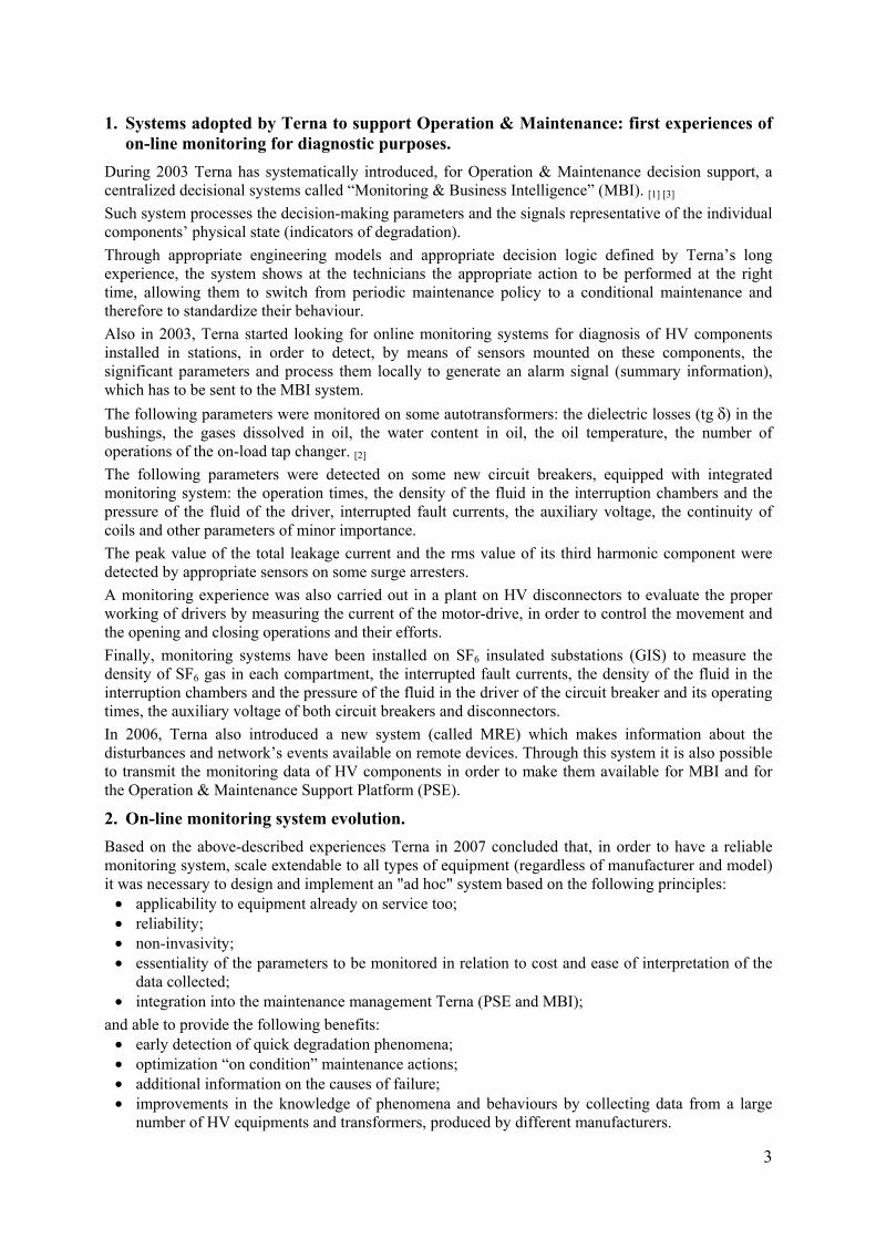
Circuit Breaker’s peripheral
In this peripheral several digital inputs can be found. They take care of timing measurements on each phase, on the basis of the timing relationship between opening command inputs (first and second circuit) and closing ones and auxiliary contacts which represent the circuit breaker’s status.
When an opening or closing input command is sent to the circuit breaker, the peripheral detect the operation times, which are sent to the central unit for further processing, such as timing tolerances, warnings etc.
Various analogue inputs to measure the SF6 density of each pole of the switch are also present; therefore not only density but also any long term (period) loss can be determined.
SF6 CT’s Peripheral
This device is installed under one of three SF6 gas current transformers, relative to a transmission line. As for circuit breaker device, it measures the gas density in the three CTs. In this way the long-term loss trends are calculated in order to prevent the need for refilling gas. In the photo the installation of a density sensor connected to one of the gas fillers and the associated device is shown.
SF6 gas sensor installation
CT’s peripheral installation
Circuit breaker peripheral installation
SF6 gas density sensor installation.
The transducer was connected to an attack for gas refilling already present on the circuit breaker.
7
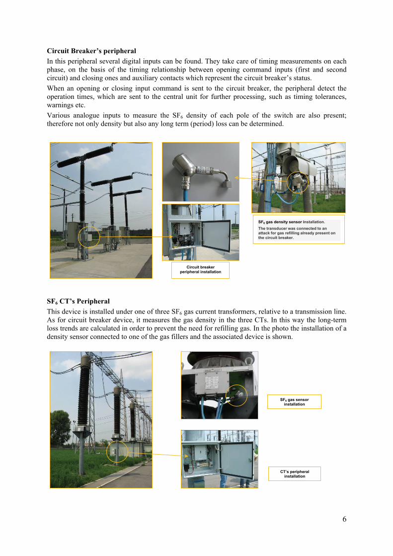
VT’s peripheral
To verify the correct operation of capacitive voltage transformers (eg. any deterioration of some elementary capacitors that make up the capacitive part of VTs), it is necessary to simultaneously measure (tmax ≤ 100 ms) the secondary voltage value of all VTs of the substation which have the same phase voltage. Anomalies can be detected by comparing the measured values of each secondary voltages and processing the results through a special dedicated algorithm; the verification is the more reliable the more numerous are the VTs analyzed.
The device simultaneously acquires the voltage values taken by the secondary clamps of the VTs and submit them to the MRE system where the average of the various measures and the relative standard deviation are computed; if the percentage of the standard deviation compared to the average value is more than twice of the accuracy class of the VTs, the component with the greatest failure probability is the one with the secondary voltage value which deviates more with respect to the average of the measures.
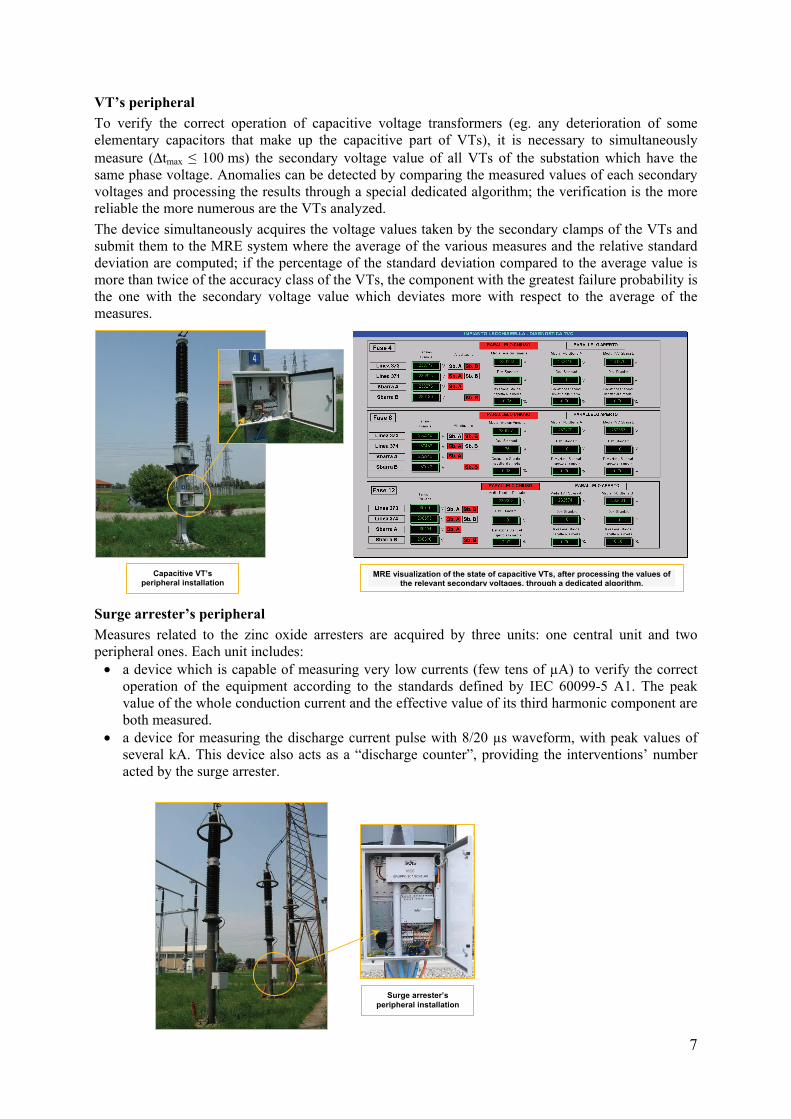
Surge arrester’s peripheral
Measures related to the zinc oxide arresters are acquired by three units: one central unit and two peripheral ones. Each unit includes: a device which is capable of measuring very low currents (few tens of µA) to verify the correct
operation of the equipment according to the standards defined by IEC 60099-5 A1. The peak value of the whole conduction current and the effective value of its third harmonic component are both measured.
a device for measuring the discharge current pulse with 8/20 µs waveform, with peak values of several kA. This device also acts as a “discharge counter”, providing the interventions’ number acted by the surge arrester.
Capacitive VT’s peripheral installation
Surge arrester’s peripheral installation
MRE visualization of the state of capacitive VTs, after processing the values of the relevant secondary voltages, through a dedicated algorithm.
8
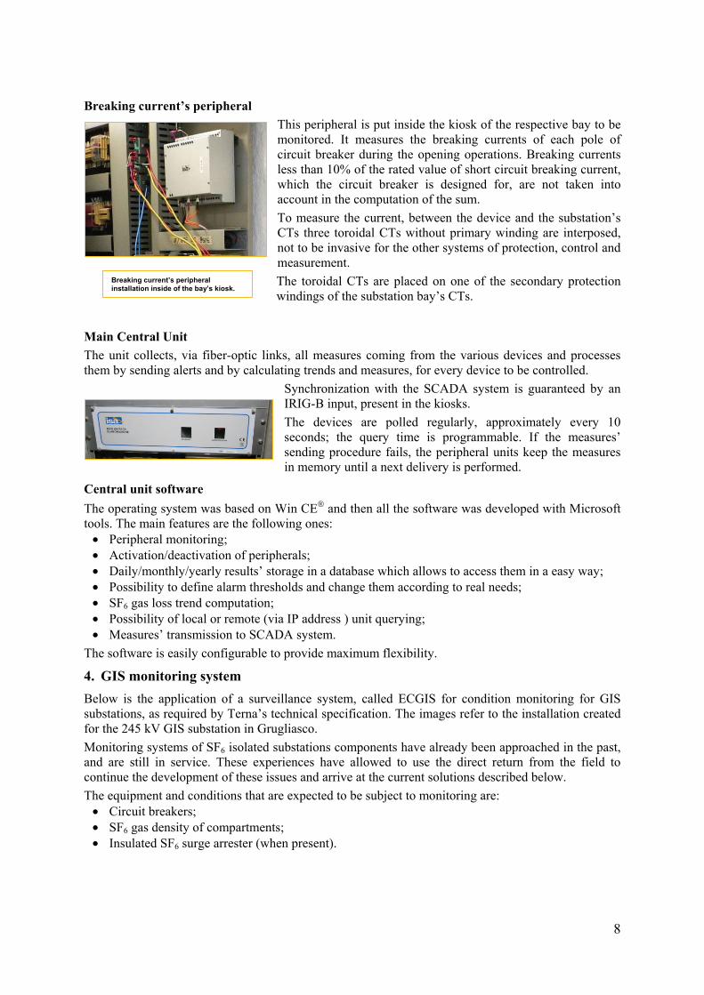
Breaking current’s peripheral
This peripheral is put inside the kiosk of the respective bay to be monitored. It measures the breaking currents of each pole of circuit breaker during the opening operations. Breaking currents less than 10% of the rated value of short circuit breaking current, which the circuit breaker is designed for, are not taken into account in the computation of the sum.
To measure the current, between the device and the substation’s CTs three toroidal CTs without primary winding are interposed, not to be invasive for the other systems of protection, control and measurement.
The toroidal CTs are placed on one of the secondary protection windings of the substation bay’s CTs.
Main Central Unit
The unit collects, via fiber-optic links, all measures coming from the various devices and processes them by sending alerts and by calculating trends and measures, for every device to be controlled.
Synchronization with the SCADA system is guaranteed by an IRIG-B input, present in the kiosks.
The devices are polled regularly, approximately every 10 seconds; the query time is programmable. If the measures’ sending procedure fails, the peripheral units keep the measures in memory until a next delivery is performed.
Central unit software
The operating system was based on Win CE and then all the software was developed with Microsoft tools. The main features are the following ones: Peripheral monitoring; Activation/deactivation of peripherals; Daily/monthly/yearly results’ storage in a database which allows to access them in a easy way; Possibility to define alarm thresholds and change them according to real needs; SF6 gas loss trend computation; Possibility of local or remote (via IP address ) unit querying; Measures’ transmission to SCADA system.
The software is easily configurable to provide maximum flexibility.
4. GIS monitoring system
Below is the application of a surveillance system, called ECGIS for condition monitoring for GIS substations, as required by Terna’s technical specification. The images refer to the installation created for the 245 kV GIS substation in Grugliasco.
Monitoring systems of SF6 isolated substations components have already been approached in the past, and are still in service. These experiences have allowed to use the direct return from the field to continue the development of these issues and arrive at the current solutions described below.
The equipment and conditions that are expected to be subject to monitoring are: Circuit breakers; SF6 gas density of compartments; Insulated SF6 surge arrester (when present).
Breaking current’s peripheral installation inside of the bay’s kiosk.

9
Cabinet with station PC and related touch screen that displays the status of the
compartments’ SF6 gas density.
The ECGIS system architecture is shown in the following picture.
It is based on a unit called EC102, installed in the bay control cubicle, which monitors the function of the circuit breaker, acquiring and processing specific signals. The EC102 is a communication network master unit of remote units, called EC103, for the monitoring of SF6 gas density of compartments and SF6 surge arrester (when present).
The EC103 units are connected via fibre optic to EC102 of the reference bay. The use of fibre-optic links allows to effectively monitor aspects of electromagnetic interference.
The EC102 units are connected via optical fibre to an optical switch placed inside the concentrator control cubicle.
A touch-screen PC, located in the same control cubicle, interacts with all EC102 units and, using specific software, displays local information and data relating to the substation’s monitoring.
The remote transmission of monitoring data is via IEC 60870-5-104 protocol.
All EC103 and EC102 units are powered by bay control cubicle. This allows one to perform ECGIS system maintenance without out-of-service of whole substation.
The toroids for the calculation of the circuit breaker breaking current are placed inside of CT’s cubicle of the same circuit breaker’s bay.
EC102 module installed inside of the
Bay CC
EC103 modules for monitoring SF6 gas
compartment density
System architecture

10
EC102 monitoring unit
The EC102 units, installed in each bay control cubicle, detect the operating times of the circuit breaker and record those events in various logs.
The operating times, collected through auxiliary contacts, are recorded for both opening and closing operations and during rapid cycles as well, such as reclosing.
Unit detects the value of the auxiliary DC voltage control device. This voltage value directly affects the operating times.
The EC102 unit also manages the signals derived from three toroidal CTs to measure the peak of primary current, so as to record the maximum interrupted current value of the circuit breaker to take account of any unidirectional component.
The measure of interrupted current allows to process the indicator "Cumulative breaking current" for the assessment of wear contacts. It is possible to set the minimum value of fault current which is interrupted from the contact wear of arc (the breaking currents less than 10% of the nominal value of short circuit breaking current are not considered strenuous).
EC102 unit provides three output contacts for reporting minor failures, severe failures, and failures of the monitoring system (self diagnosis).
All inputs are optic-insulated and isolated each other (2,5 kVac) by type of circuit.
The ports include a dedicated RS-232 for updating the firmware and modifying the internal parameters, notwithstanding the possibility of remote update.
EC103 remote and auxiliary unit
In the case of SF6 insulated substation, monitoring of SF6 gas density in the different compartments is of fundamental importance in keeping the insulation level as well as in early detecting possible leakages.
Each EC103 unit allows to interface with three field signals originating from several sensors employed for continuous monitoring of the SF6 gas density.
Each EC103 acts as an optical repeater so as to distribute the communication network and build a bus.
On the side the alarm screen related to the monitoring of SF6 density in a compartment is showed.
In addition to the indication of a gas leak in progress, the time that should elapse to the onset of low pressure warning signal is also considered. Such information allows the operational staff to schedule the refilling timing.
Management Software of ECGIS system
ECGIS system is managed and configured by the software installed on touch screen PC placed inside the concentrator cubicle.
The software shows the instantaneous state of the parameters of all the compartments monitored by the system.
The log data collected by the system are sent, by request, to Terna’s remote server where their operating statistics will be carried out.
SF6 gas sensor Screen that displays SF6 gas density alarm.

11
Instantaneous information displaying and alerting is still possible in the concentrator PC, log files being stored in the EC102 units.
The call and the subsequent download by Terna’s Remote Log Server occur on the concentrator PC.
5. Transformers
The monitoring of power transformers has been made using sensors that are already commercially available.
The dissolved gases are monitored through a gas-alarm device; the temperatures are monitored via Pt100 probes; the currents are measured through the bay’s CTs. All the signals are acquired directly in 4-20 mA or converted in such format, and sent to the peripheral monitoring unit (UM).
During the year 2011, the remotization work has started on transformers in service already equipped with sensors, and the real time parameters of nine transformers are available on-line in PSE.
Pt100 resistance thermometers
probes
Gas dissolved in oil device
System architecture
PSE’s screen that displays transformer’s parameters values
PSE
router
MBI
A/D Converter
IEDMRE
ATR with new DGA sensor(digital output) Station Computer
ATR with DGA sensor(analog output)
MRECentral Unit
RIO Yes
No
MRE ?
Yes
NoMRE ?
12
6. Conclusions
The on-line monitoring systems described above are very flexible since they are applicable to new substations, as well as to all equipment already in service which need to be monitored.
In addition, central units can be implemented with various protocols to communicate with the SCADA system.
The installation of these systems has a minimal impact on existing circuits and can be implemented quickly. If applied on a large scale it is a useful tool which allows to switch from a time-based maintenance to a condition-based maintenance, thus reducing costs, improving substations’ safety and increasing the useful life of HV equipments and transformers.
Bibliography [1] D. Bisci, G. Corsetti, M.Gallanti: "MBI il sistema di supporto al processo di manutenzione per la rete di trasmissione italiana" - ANIPLA-Enersis 2004, Aprile 2004 [2] S. Mobili, A. Giorgi, E. Di Bartolomeo: "Tecnologie per migliorare la disponibilità ed affidabilità della rete di trasmissione nazionale" - Rendiconti AEI -Genova, Giugno 2004 [3] E. Di Bartolomeo, A. Valant: "Sistemi di Business Intelligence a supporto della manutenzione degli impianti di trasmissione dell'energia elettrica" - Rendiconti AEIT-Capri, Settembre 2006 [4] G. Amadi, M. Puricelli, M. Gastaldelli – The new integrated on-line continuous substation diagnostic system: system description and results – Conferenza internazionale CPRI (Central Power Research Institute), Bangalore, Gennaio 2008 [5] G.C. Montanari, A. Cavallini, D. Fagiani, E. Vellucci: "Experience on partial discharge monitoring of power transformers" – IEEE ISEI, Indianapolis, Indiana (USA), Ottobre 2004