the perceptron is helping man understand how his brain
TRANSCRIPT
July se, 1960
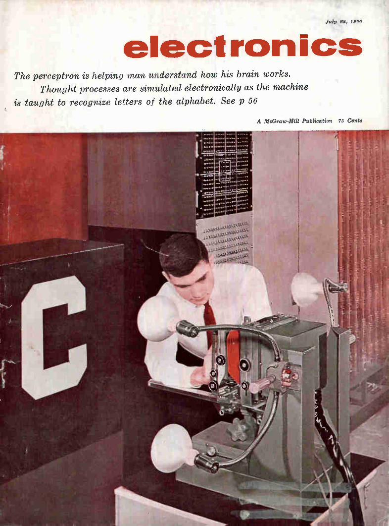
electronics The perceptron is helping man understand how his brain works.
Thought processes are simulated electronically as the machine
is taught to recognize letters of the alphabet. See p 56
A McGraw-Hill Publication 75 Cents
Call your rep today for a
demonstration of one of these
POPULAR
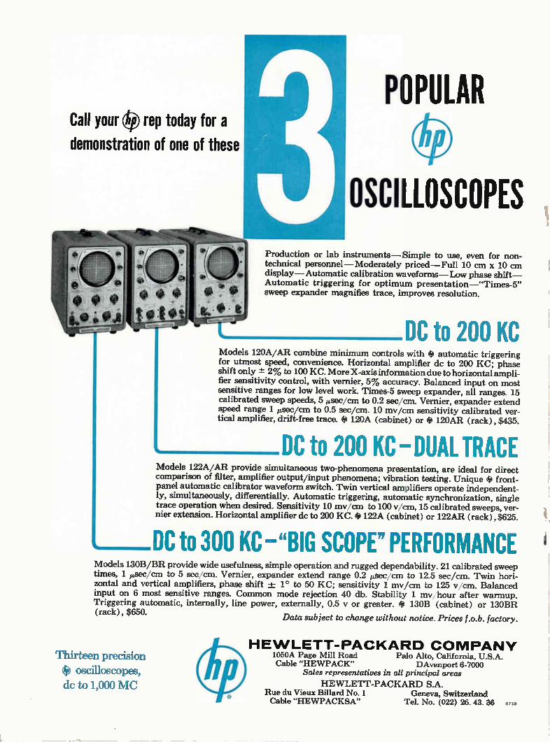
OSCILLOSCOPES Production or lab instruments— Simple to use, even for non-technical personnel—Moderately priced—Full 10 cm x 10 cm display—Automatic calibration waveforms—Low phase shift— Automatic triggering for optimum presentation—"Times-5" sweep expander magnifies trace, improves resolution.
DC to 200 KC Models 120A/AR combine minimum controls with # automatic triggering for utmost speed, convenience. Horizontal amplifier de to 200 KC; phase shift only ± 2% to 100 KC. More X-axis information due to horizontal ampli-fier sensitivity control, with vernier, 5% accuracy. Balanced input on most sensitive ranges for low level work. Times-5 sweep expander, all ranges. 15 calibrated sweep speeds, 5 ,sec/cm to 0.2 sec/cm. Vernier, expander extend speed range 1 ,,,,,see/cm to 0.5 sec/cm. 10 my/cm sensitivity calibrated ver-tical amplifier, drift-free trace. # 120A (cabinet) or e 120AR (rack) , $435.
DC to 200 KC DUAL TRACE Models 122A/AR provide simultaneous two-phenomena presentation, are ideal for direct comparison of filter, amplifier output/input phenomena; vibration testing. Unique # front-panel automatic calibrator waveform switch. Twin vertical amplifiers operate independent-ly, simultaneously, differentially. Automatic triggering, automatic synchronization, single trace operation when desired. Sensitivity 10 my cm to 100 v/ern, 15 calibrated sweeps, ver-nier extension. Horizontal amplifier dc to 200 KC. # 122A (cabinet) or 122AR (rack) , $625.
DC to 300 KC —"BIG SCOPE" PERFORMANCE Models 130B/BR provide wide usefulness, simple operation and rugged dependability. 21 calibrated sweep times, 1 ttsec,/cm to 5 sec cm. Vernier, expander extend range 0.2 p,sec/cm to 12.5 sec/cm. Twin hori-zontal and vertical amplifiers, phase shift -4- 1° to 50 KC; sensitivity 1 my/cm to 125 v, cm. Balanced input on 6 most sensitive ranges. Common mode rejection 40 db. Stability 1 my hour after warmup. Triggering automatic, internally, line power, externally, 0.5 y or greater. # 130B (cabinet) or 130BR (rack) , $650.
Data subject to change without notice. Prices f.o.b. factory.
Thirteen precision e oscilloscopes, de to 1,000 MC
HEWLETT-PACKARD COMPANY 1050A Page Mill Road Palo Alto, California, U.S.A. Cable "HEWPACK" DAvenport 6-7000
Sales representatives in all principal areas
HEWLETT-PACKARD S.A. Rue du Vieux Billard No. 1 Geneva, Switzerland Cable "HEWPACKSA" Tel. No. (022) 26. 43. 36 6715
July 22, 1960
electronics A McGraw-Hill Publication 75 Cents
W. W. MacDONALD, Editor
J. M. CARROLL, Managing Editor SENIOR ASSOCIATE EDITORS: Samuel Weber, Roland J. Charest. ASSOCIATE EDITORS: Frank Leary, Michael F. Tomaino, Sylvester P. Carter, William P. O'Brien, John
F. Mason, William E. Bushor,
Thomas Emma, Sy Vogel, Leslie Solomon, M. M. Perugini, George J. clynn. ASSISTANT EDITORS:
Michael F. Wolff, Nilo Lind-gren, Stanley Fraud. REGIONAL EDITORS: Harold C. Hood (Pacific
Coast, Los Angeles), Thomas Ma-guire (New England, Boston).
MARKET RESEARCH EDITOR: Ed-ward DeJongh. BUYERS' GUIDE EDITOR: George Sideris. ART DI-RECTOR: Harry Phillips; Howard R. Berry. PRODUCTION EDITOR:
John C. Wright, Jr. EDITORIAL ASSISTANTS: Gloria J. Filippone,
Arlene Schilp, Bernice Duffy, Pa-
tricia Martine, Lorraine Rossi, Vie, ginia T. Bastian, Ruth Ayres.
JAMES GIRDWOOD, Publisher
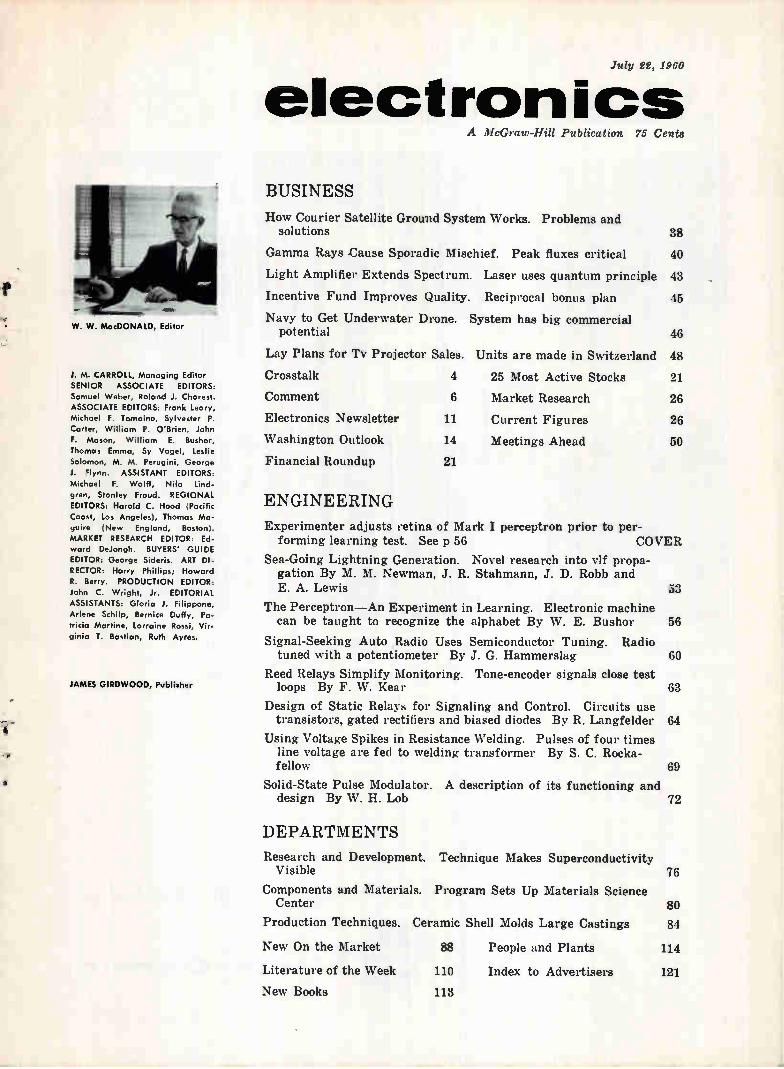
BUSINESS
How Courier Satellite Ground System Works. Problems and solutions
Gamma Rays Cause Sporadic Mischief. Peak fluxes critical
Light Amplifier Extends Spectrum. Laser uses quantum principle
Incentive Fund Improves Quality. Reciprocal bonus plan
Navy to Get Underwater Drone. System has big commercial potential
Lay Plans for Tv Projector Sales.
Crosstalk
Comment
Electronics Newsletter
Washington Outlook
Financial Roundup
4
6
11
14
21
38
40
43
45
46
Units are made in Switzerland 48
21
26
25 Most Active Stocks
Market Research
Current Figures
Meetings Ahead
26
so
ENGINEERING
Experimenter adjusts retina of Mark I perceptron prior to per-forming learning test. See p 56 COVER
Sea-Going Lightning Generation. Novel research into vlf propa-gation By M. M. Newman, J. R. Stahmann, J. D. Robb and E. A. Lewis 53
The Perceptron—An Experiment in Learning. Electronic machine can be taught to recognize the alphabet By W. E. Bushor 56
Signal-Seeking Auto Radio Uses Semiconductor Tuning. Radio tuned with a potentiometer By J. G. Hammerslag 60
Reed Relays Simplify Monitoring. Tone-encoder signals close test loops By F. W. Kear 63
Design of Static Relays for Signaling and Control. Circuits use transistors, gated rectifiers and biased diodes By R. Langfelder 64
Using Voltage Spikes in Resistance Welding. Pulses of four times line voltage are fed to welding transformer By S. C. Rocka-fellow 69
Solid-State Pulse Modulator. A description of its functioning and design By W. H. Lob
DEPARTMENTS
Research and Development. Technique Makes Superconductivity Visible
Components and Materials. Program Sets Up Materials Science Center
Production Techniques.
New On the Market
Literature of the Week
New Books
72
76
80
Ceramic Shell Molds Large Castings 84
88 People and Plants 114
110 Index to Advertisers 121
113
SILICONE NEWS from Dow Corning
When Miniaturizing
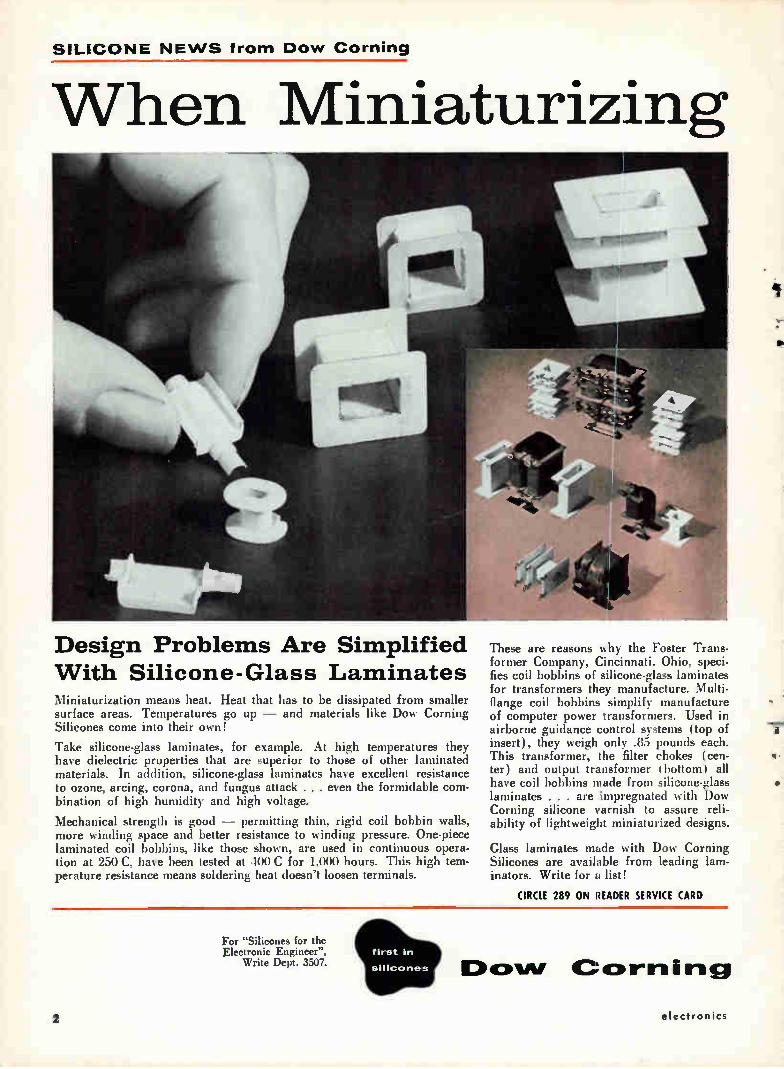
Design Problems Are Simplified With Silicone-Glass Laminates Miniaturization means heat. Heat that has to be dissipated from smaller surface areas. Temperatures go up — and materials like Dow Corning Silicones come into their own!
Take silicone-glass laminates, for example. At high temperatures they have dielectric properties that are superior to those of other laminated materials. In addition, silicone-glass laminates have excellent resistance to ozone, arcing, corona, and fungus attack . . . even the formidable com-bination of high humidity and high voltage.
Mechanical strength is good — permitting thin, rigid coil bobbin walls, more winding space and better resistance to winding pressure. One-piece laminated coil bobbins, like those shown, are used in continuous opera-tion at 250 C, have been tested at 400 C for 1,000 hours. This high tem-perature resistance means soldering heat doesn't loosen terminals.
For "Silicones for the Electronic Engineer",
Write Dept. 3507.
These are reasons why the Foster Trans-former Company, Cincinnati. Ohio, speci-fies coil bobbins of silicone-glass laminates for transformers they manufacture. Multi-flange coil bobbins simplify manufacture of computer power transformers. Used in airborne guidance control systems (top of insert), they weigh only .85 pounds each. This transformer, the filter chokes (cen-ter) and output transformer I bottom) all have coil bobbins made from silicone-glass laminates . . . are impregnated with Dow Corning silicone varnish to assure reli-ability of lightweight miniaturized designs.
Glass laminates made with Dow Corning Silicones are available from leading lam-inators. Write for a list!
CIRCLE 289 ON READER SERVICE CARD
E) out/ Cc»rriini
1r •
electronics
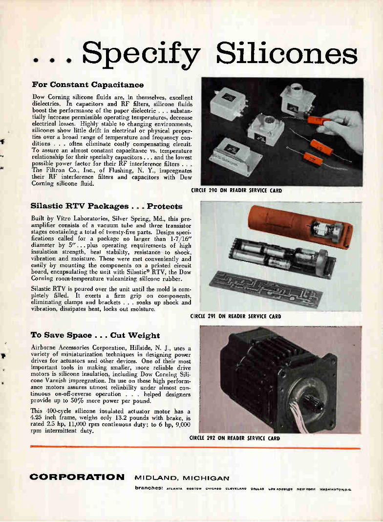
. Specify Silicones For Constant Capacitance
Dow Corning silicone fluids are, in themselves, excellent dielectrics. In capacitors and RF filters, silicone fluids boost the performance of the paper dielectric . . . substan-tially increase permissible operating temperatures, decrease electrical losses. Highly stable to changing environments, silicones show little drift in electrical or physical proper-ties over a broad range of temperature and frequency con-ditions . . . often eliminate costly compensating circuit. To assure an almost constant capacitance vs. temperature relationship for their specialty capacitors. .. and the lowest possible power factor for their RF interference filters . . . The Filtron Co., Inc., of Flushing, N. Y., impregnates their RF interference filters and capacitors with Dow Corning silicone fluid.
290 ON READER SERVICE CARD CIRCLE
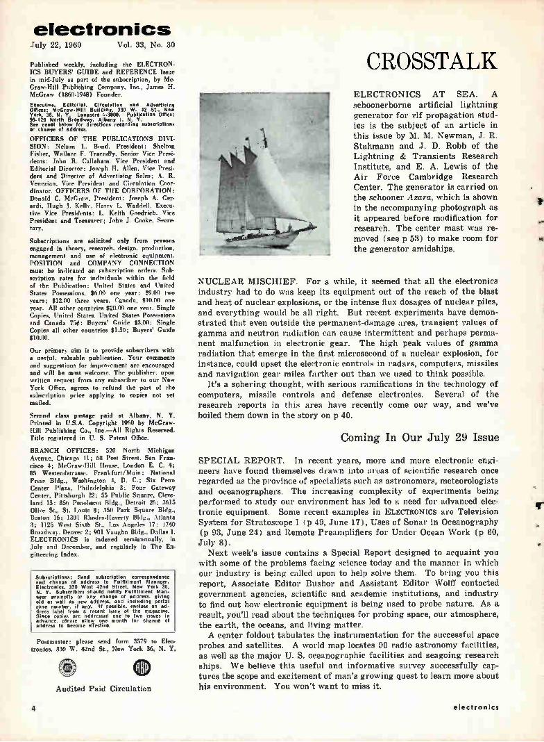
Silastic RTV Packages . . . Protects
Built by Vitro Laboratories, Silver Spring, Md., this pre-amplifier consists of a vacuum tube and three transistor stages containing a total of twenty-five parts. Design speci-fications called for a package no larger than 1-7/16" diameter by 5" ... plus operating requirements of high insulation strength, heat stability, resistance to shock, vibration and moisture. These were met conveniently and easily by mounting the components on a printed circuit board, encapsulating the unit with Silastic® RTV, the Dow Corning room-temperature vulcanizing silicone rubber.
Silastic RTV is poured over the unit until the mold is com-pletely filled. It exerts a firm grip on components, eliminating clamps and brackets . . . soaks up shock and vibration, dissipates heat, locks out moisture.
291 ON READER SERVICE CARD CIRCLE
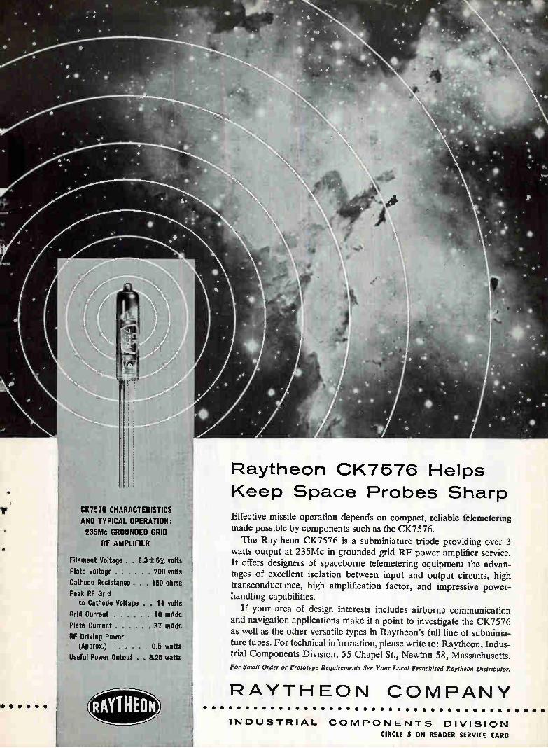
To Save Space . . . Cut Weight
Airborne Accessories Corporation, Hillside, N. J., uses a variety of miniaturization techniques in designing power drives for actuators and other devices. One of their most important tools in making smaller, more reliable drive motors is silicone insulation, including Dow Corning Sili-cone Varnish impregnation. Its use on these high perform-ance motors assures utmost reliability under almost con-tinuous on-off-reverse operation . . . helped designers provide up to 50% more power per pound.
This 400-cycle silicone insulated actuator motor has a 4.25 inch frame, weighs only 13.2 pounds with brake, is rated 2.5 hp, 11,000 rpm continuous duty; to 6 hp, 9,000 rpm intermittent duty.
292 ON READER SERVICE CARD CIRCLE
COR PO RATI 0 N m I D LAN D, M 10H 'GAN
branches: ATLAN,.... BOSTON CHICAGO CLEVELAND GALSAS SOS ANGELES NEW VOSS WASITINGTON.0 C.
electronics July 22, 1960 Vol. 33, No. 30
Published weekly, including the ELECTRON-ICS BUYERS' GUIDE and REFERENCE Issue in mid-July as part of the subscription, by Mc-Graw-Hill Publishing Company, Inc.. James H. McGraw (1860-1948) Founder.
Executive, Editorial. Circulation and Advertising OfRees: McGraw-Hill Building, 330 W. 42 St., New York. 36, N. Y. Longacre 4-3000. Publication Office: 99-129 North Broadway, Albany I. N. Y. See panel below for directions regarding subscriptions or change of address.
OFFICERS OF THE PUBLICATIONS DIVI-SION: Nelson L. Bond, President: Shelton Fisher, Wallace F. Traendly, Senior Vice Presi-dents; John R. Callaham, Vice President and Editorial Director; Joseph H. Allen. Vice Presi-dent and Director of Advertising Sales; A. R. Venezian, Vire President and Circulation Coor-dinator. OFFICERS OF THE CORPORATION: Donald C. McGraw, President; Joseph A. Ger-ardi, IIngh J. Kelly. Harry L. Waddell. Execu-tive Vice Presidents; L. Keith Goodrich. Vice President and Treasurer; John J. Cooke. Secre-tary.
Subscriptions are solicited only from persons engaged in theory, research, design, production, management and use of electronic equipment. POSITION and COMPANY CONNECTION must be indicated on subscription orders. Sub-scription rates for individuals within the field of the Publication: United States and United States Possessions, $6.00 one year; $9.00 two years; $12.00 three years. Canada, $10.00 one year. All other countries $20.00 one year. Single Copies, United States, United States Possessions and Canada 754; Buyers' Guide $3.00; Single Copies all other countries $1.50; Buyers' Guide $10.00.
Our primary aim is to provide subscribers with a useful, valuable publication. Your comments and suggestions for improvement are encouraged and will be most welcome. The publisher, upon written request from any subscriber to our New York Office, agrees to refund the part of the subscription price applying to copies not yet mailed.
Second clase postage paid at Albany, N. Y. Printed in U.S.A. Copyright 1960 by McGraw-Hill Publishing Co., Inc.—All Rights Reserved. Title registered in U. S. Patent Office.
BRANCH OFFICES: 520 North Michigan Avenue, Chicago 11; 68 Post Street. San Fran-cisco 4; McGraw-Hill House, London E. C. 4; 85 Westendstrasse, Frankfurt/Main; National Press Bldg., Washington 4, D. C.; Six Penn Center Plaza, Philadelphia 3; Four Gateway Center, Pittsburgh 22; 55 Public Square, Cleve-land 13; 856 Penobscot Bldg., Detroit 26: 3615 Olive St., St. Louis 8; 350 Park Square Bldg., Boston 16; 1301 Rhodes-Haverty Bldg., Atlanta 3; 1125 West Sixth St., Loa Angeles 17: 1740 Broadway, Denver 2; 901 Vaughn Bldg., Dallas 1. ELECTRONICS is indexed semiannually, in July and December, and regularly in The En-gineering Index.
Subscriptions: Send subscription correspondence and change of address to Fulfillment Manager. Electronics, 330 West 42nd Street. New York 36. N. Y. Subscribers should notify Fulfillment Man-ager promptly of any change of address, giving old as well as new address, and including pontai zone number. if any. If possible, enclose an ad-dress label from a recent issue of the magazine. Since copies are addressed one to two issues in advance, please allow one month for change of address to become effective.
Postmaster: please send form 3579 to Elec-tronics, 330 W. 42nd St., New York 36, N. Y.
gBP Audited Paid Circulation
CROSSTALK ELECTRONICS AT SEA. A schoonerborne artificial lightning generator for vif propagation stud-ies is the subject of an article in this issue by M. M. Newman, J. R. Stahmann and J. D. Robb of the Lightning & Transients Research Institute, and E. A. Lewis of the Air Force Cambridge Research Center. The generator is carried on the schooner Azara, which is shown in the accompanying photograph as it appeared before modification for research. The center mast was re-moved (see p 53) to make room for the generator amidships.
NUCLEAR MISCHIEF. For a while, it seemed that all the electronics industry had to do was keep its equipment out of the reach of the blast and heat of nuclear explosions, or the intense flux dosages of nuclear piles, and everything would be all right. But recent experiments have demon-strated that even outside the permanent-damage area, transient values of gamma and neutron radiation can cause intermittent and perhaps perma-nent malfunction in electronic gear. The high peak values of gamma radiation that emerge in the first microsecond of a nuclear explosion, for instance, could upset the electronic controls in radars, computers, missiles and navigation gear miles farther out than we used to think possible.
It's a sobering thought, with serious ramifications in the technology of computers, missile controls and defense electronics. Several of the research reports in this area have recently come our way, and we've boiled them down in the story on p 40.
Coming In Our July 29 Issue
SPECIAL REPORT. In recent years, more and more electronic engi-neers have found themselves drawn into areas of scientific research once regarded as the province of specialists such as astronomers, meteorologists and oceanographers. The increasing complexity of experiments being performed to study our environment has led to a need for advanced elec-tronic equipment. Some recent examples in ELECTRONICS are Television System for Stratoscope I ( p 49, June 17), Uses of Sonar in Oceanography (p 93, June 24) and Remote Preamplifiers for Under Ocean Work (p 60, July 8).
Next week's issue contains a Special Report designed to acquaint you with some of the problems facing science today and the manner in which our industry is being called upon to help solve them. To bring you this report, Associate Editor Bushor and Assistant Editor Wolff contacted government agencies, scientific and academic institutions, and industry to find out how electronic equipment is being used to probe nature. As a result, you'll read about the techniques for probing space, our atmosphere, the earth, the oceans, and living matter. A center foldout tabulates the instrumentation for the successful space
probes and satellites. A world map locates 90 radio astronomy facilities, as well as the major U. S. oceanographic facilities and seagoing research ships. We believe this useful and informative survey successfully cap-tures the scope and excitement of man's growing quest to learn more about his environment. You won't want to miss it.
4 electronics
e • • • • •
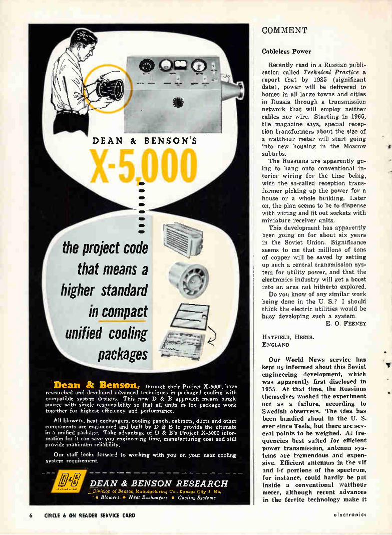
41, CK7576 CHARACTERISTICS
AND TYPICAL OPERATION:
235Mc GROUNDED GRID
RF AMPLIFIER
Filament Voltage . . 6.3 I 5% volts
Plate Voltage 200 volts
Cathode Resistance . 150 ohms
Peak RF Grid to Cathode Voltage . 14 volts
Grid Current 10 mAdc
Plate Current 37 mAdc
RF Driving Power (Approx.) 0.5 watts
Useful Power Dube . 3.25 watts
Raytheon CK7576 Helps
Keep Space Probes Sharp
Effective missile operation depends on compact, reliable telemetering made possible by components such as the CK7576.
The Raytheon CK7576 is a subminiature triode providing over 3 watts output at 235Mc in grounded grid RF power amplifier service. It offers designers of spaceborne telemetering equipment the advan-tages of excellent isolation between input and output circuits, high transconductance, high amplification factor, and impressive power-handling capabilities.
If your area of design interests includes airborne communication and navigation applications make it a point to investigate the CK7576 as well as the other versatile types in Raytheon's full line of subminia-ture tubes. For technical information, please write to: Raytheon, Indus-trial Components Division, 55 Chapel St., Newton 58, Massachusetts.
For Small Order or Prototype Requirements See Your Local Franchised Raytheon Distributor.
RAYTHEON COMPANY
INDUSTRIAL COMPONENTS DIVISION CIRCLE 5 ON READER SERVICE CARD
•
DEAN & BEN SON'S
X51.000
the project code that means a
higher standard in compact
unified cooling packages
Dean & Benson, through their Project X-5000, have researched and developed advanced techniques in packaged cooling with compatible system designs. This new D & B approach means single source with single responsibility so that all units in the package work together for highest efficiency and performance.
All blowers, heat exchangers, cooling panels, cabinets, ducts and other components are engineered and built by D & B to provide the ultimate in a unified package. Take advantage of D & B's Project X-5000 infor-mation for it can save you engineering time, manufacturing cost and still provide maximum reliability.
Our staff looks forward to working with you on your next cooling system requirement.
DEAN & BENSON RESEARCH Division of Benson ManutacturIng Co., Kuns.us C.ty I. Mo.
' • Blowers • Heat Exchangers • Cooling Systems
COMMENT
Cableless Power
Recently read in a Russian publi-cation called Technical Practice a report that by 1985 (significant date), power will be delivered to homes in all large towns and cities in Russia through a transmission network that will employ neither cables nor wire. Starting in 1965, the magazine says, special recep-tion transformers about the size of a watthour meter will start going into new housing in the Moscow suburbs. The Russians are apparently go-
ing to hang onto conventional in-terior wiring for the time being, with the so-called reception trans-former picking up the power for a house or a whole building. Later on, the plan seems to be to dispense with wiring and fit out sockets with miniature receiver units.
This development has apparently been going on for about six years in the Soviet Union. Significance seems to me that millions of tons of copper will be saved by setting up such a central transmission sys-tem for utility power, and that the electronics industry will get a boost into an area not hitherto explored. Do you know of any similar work
being done in the U. S.? I should think the electric utilities would be busy developing such a system.
E. O. FEENEY
HATFIELD, HERTS. ENGLAND
Our World News service has kept us informed about this Soviet engineering development, which was apparently first disclosed in 1955. At that time, the Russians themselves washed the experiment out as a failure, according to Swedish observers. The idea has been bandied about in the U. S. ever since Tesla, but there are sev-eral points to be weighed. At fre-quencies best suited for efficient power transmission, antenna sys-tems are tremendous and expen-sive. Efficient antennas in the vif and 1-f portions of the spectrum, for instance, could hardly be put inside a conventional watthour meter, although recent advances in the ferrite technology make it
6 CIRCLE 6 ON READER SERVICE CARD electronics
KT SERIES KR SERIES
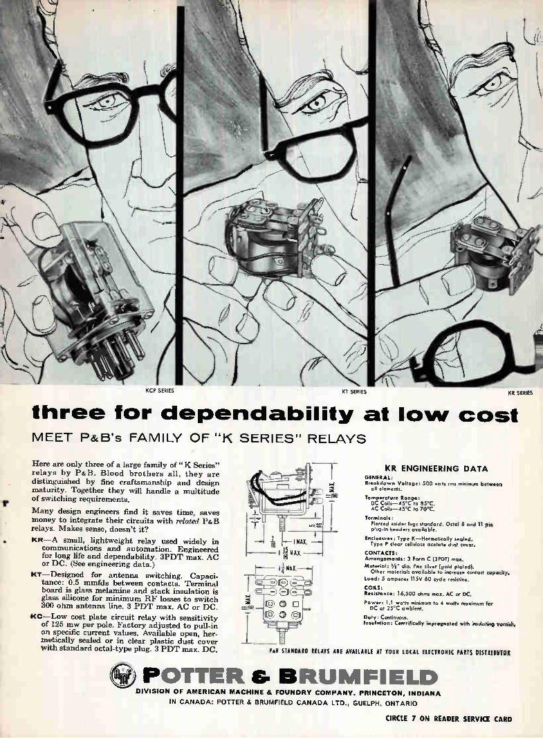
three for dependability at low cost MEET P&B's FAMILY OF "K SERIES" RELAYS
Here are only three of a large family of "K Series" relays by P&B. Blood brothers all, they are distinguished by fine craftsmanship and design maturity. Together they will handle a multitude of switching requirements.
Many design engineers find it saves time, saves money to integrate their circuits with related P&B relays. Makes sense, doesn't it?
• KR--A small, lightweight relay used widely in communications and automation. Engineered for long life and dependability. 3PDT max. AC or DC. (See engineering data.)
KT— Designed for antenna switching. Capaci-tance: 0.5 mmfds between contacts. Terminal board is glass melamine and stack insulation is glass silicone for minimum RF losses to switch 300 ohm antenna line. 3 PDT max. AC or DC.
KC— Low cost plate circuit relay with sensitivity of 125 mw per pole. Factory adjusted to pull-in on specific current values. Available open, her-metically sealed or in clear plastic dust cover with standard octal-type plug. 3 PDT max. DC.
KR ENGINEERING DATA GENERAL: Breakdown Voltage: 500 volts rras minimum between
all elements.
Temperature Range: DC Coils-45'C to 85°C. AC Coils-45°C to 70°C.
Terminals: Pierced solder lugs standard. Octal 8 and 1 I pin plug-in headers available.
Enclosures: Type K—Hermetically sealed. Type P clear cellulose acetate dust cover.
CONTACTS: Arrangements: 3 Form C (3PDT) max.
Material: Vs" dia, fine silver (gold plated). Other materials available to increase contact capadtP.
Load: 5 amperes 115V 60 cycle resistive.
COILS: Resistance: 16,500 ohms max. AC or DC.
Power: 1.1 watts minimum to 4 watts maximum for DC at 25°C ambient.
Duty: Continuous. Insulation: Centrifically impregnated with insulating senile
Pal STANDARD RELAYS ARE AVAILABLE AT YOUR LOCAL ELECTRONIC PARTS DISTRIIUTOlt
POTTER G BRUMFIELD DIVISION OF AMERICAN MACHINE & FOUNDRY COMPANY, PRINCETON, INDIANA
IN CANADA: POTTER & BRUMFIELD CANADA LTD., GUELPH, ONTARIO
CIRCLE 7 ON READER SERVICE CARD
d e modabilit GATES
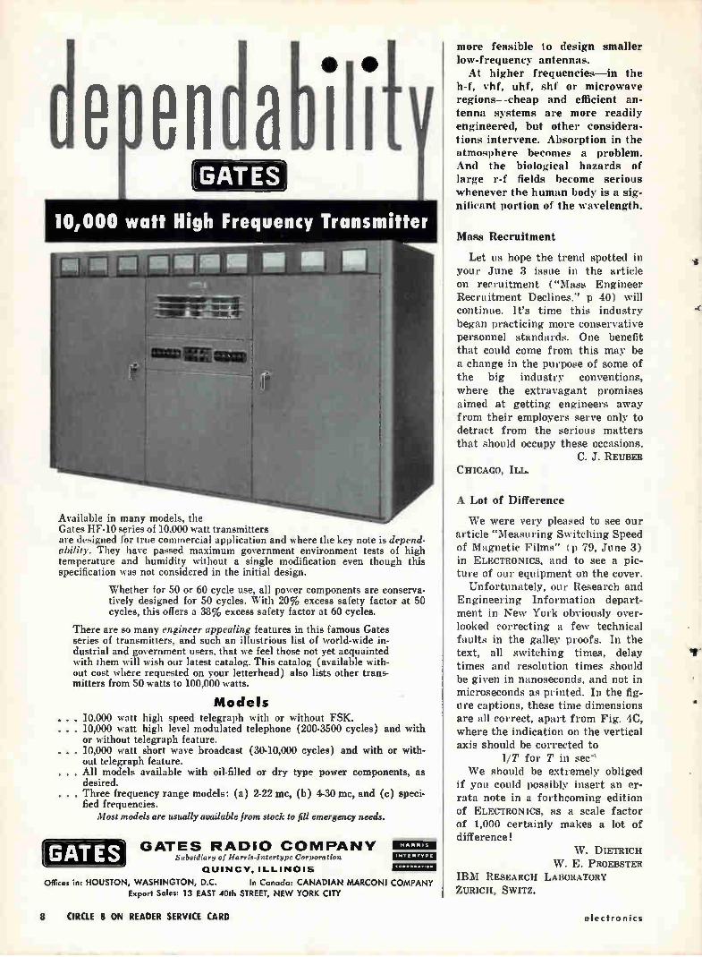
10,000 watt High Frequency Transmitter
immoismor mom , emime,upg--WNW ier - — arm or
DMZ già Mac
Available in many models, the Gates HF-10 series of 10,000 watt transmitters are designed fo'r true commercial application and where the key note is depend-ability. They have passed maximum government environment tests of high temperature and humidity without a single modification even though this specification was not considered in the initial design.
Whether for 50 or 60 cycle use, all power components are conserva-tively designed for 50 cycles. With 20% excess safety factor at 50 cycles, this offers a 38% excess safety factor at 60 cycles.
There are so many engineer appealing features in this famous Gates series of transmitters, and such an illustrious list of world-wide in-dustrial and government users, that we feel those not yet acquainted with them will wish our latest catalog. This catalog (available with-out cost where requested on your letterhead) also lists other trans-mitters from 50 watts to 100,000 watts.
Models . . . 10,000 watt high speed telegraph with or without FSK. ▪ 10,000 watt high level modulated telephone (200-3500 cycles) and with
or without telegraph feature. . . . 10,000 watt short wave broadcast (30-10,000 cycles) and with or with-
out telegraph feature. . . . All models available with oil-filled or dry type power components, as
desired. • Three frequency range models: (a) 2-22 mc, (b) 4-30 mc, and (c) speci-
fied frequencies. Most models are usually available from stock to fill emergency needs.
GATES GATES RADIO COMPANY Subsidiary of Harris-I atertype Corporation
QUINCY. ILLINOIS
Offices in: HOUSTON, WASHINGTON, D.C. In Canada: CANADIAN MARCONI COMPANY Export Sales: 13 EAST 40th STREET, NEW YORK CITY
UM= IL1Z43;11ZU =1=11
more feasible to design smaller low-frequency antennas. At higher frequencies—in the
h-f, vhf, uhf, shf or microwave regions—cheap and efficient an-tenna systems are more readily engineered, but other considera-tions intervene. Absorption in the atmosphere becomes a problem. And the biological hazards of large r-f fields become serious whenever the human body is a sig-nificant portion of the wavelength.
Mass Recruitment
Let us hope the trend spotted in your June 3 issue in the article on recruitment ("Mass Engineer Recruitment Declines." p 40) will continue. It's time this industry began practicing more conservative personnel standards. One benefit that could come from this may be a change in the purpose of some of the big industry conventions, where the extravagant promises aimed at getting engineers away from their employers serve only to detract from the serious matters that should occupy these occasions.
C. J. REUBEB CHICAGO, ILL.
A Lot of Difference
We were very pleased to see our article "Measuring Switching Speed of Magnetic Films" ( p 79, June 3) in ELECTRONICS, and to see a pic-ture of our equipment on the cover.
Unfortunately, our Research and Engineering Information depart-ment in New York obviously over-looked correcting a few technical faults in the galley proofs. In the text, all switching times, delay times and resolution times should be given in nanoseconds, and not in microseconds as printed. In the fig-ure captions, these time dimensions are all correct, apart from Fig. 4C, where the indication on the vertical axis should be corrected to
1/T for T in sec' We should be extremely obliged
if you could possibly insert an er-rata note in a forthcoming edition of ELECTRONICS, as a scale factor of 1,000 certainly makes a lot of difference!
W. DIETRICH W. E. PROEBSTER
IBM RESEARCH LABORATORY ZURICH, SWITZ.
8 CIRCLE 8 ON READER SERVICE CARD electronics
specify ITE Relays for Reliability
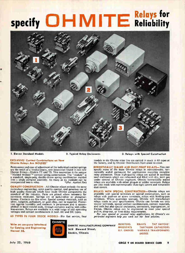
1. Eleven Standard Models 2. Typical Relay Enclosures 3. Relays with Special Construction
EXCLUSIVE! Contact Combinations on New Ohmite Relays Are MOLDED'
Permanence and ease of adjustment of the individual contact springs are the result of a revolutionary, new innovation found in two new Ohmite Relays—Models TT and TS. This innovation is the unique "Molded Module"* contact spring construction. The "module" is a standard, single-pole, double-throw spring combination molded into a single compact assembly. As many as six modules can be incorporated into a relay. *(Pat. Applied For)
QUALITY CONSTRUCTION —All Ohmite relays embody the same meticulous engineering, strict quality control, and generous use of high quality materials which have made Ohmite componènts the standard of the industry. Parts are plated where necessary for corrosion resistance. Springs are of nickel-silver or phosphor-bronze. Contacts are fine silver. Special contact materials, such as silver, tungsten, palladium, or gold alloy, can be supplied. Protec-tion against humidity and moisture is paramount and is accom-plished in layer-wound coils, through complete sealing with cellu-lose-acetate. Relays are available in a wide range of coil operating voltages and contact combinations in both AC and DC types.
65 TYPES IN FOUR STOCK morui s For fast service, four
OHMITE Write on company letterhead for Catalog and Engineering Manual 58.
models in the Ohmite relay line are carried in stock in 65 types at the factory, and by Ohmite Distributors from coast to coast.
HERMETICALLY SEALED AND DUST-TIGHT RELAYS—You can specify many of the basic Ohmite relays in nonremovable, her-metically sealed enclosures for applications requiring complete relay protection. These high-quality relays are sealed in seamless steel enclosures which are exhausted and filled with dry, inert gas under control of Ohmite engineers. Ohmite hermetically sealed relays are available with either plug-in or solder terminals. Relays are also made with nonremovable dust-tight covers and removable dust covers.
RELAYS WITH SPECIAL CONSTRUCTION—Ohmite relays are available with special terminals or special construction, such as relays with push-on or screw terminals, relays with binding-post terminals. Where quantities warrant, Ohmite will manufacture relays made to your specifications. Ohmite can furnish not only special terminals, special contact combinations, contact materials, and coils but also special enclosures, connectors, impregnation, or frames. Ohmite relays can be engineered to meet your special pull-in, drop-out, or time-delay requirements. For your special or unusual relay applications, let Ohmite's ex-
perienced engineers help you work out the best solution.
' OHMITE MANUFACTURING COMPANY RESISTORS RELAYS TAP SWITCHE RHEOSTATS TANTALUM CAPACITORS
R.F. CHOKES VARIABLE TRANSFORMERS
DIODES
3610 Howard Street,
Skokie, Illinois
July 22, 1960 CIRCLE 9 ON READER SERVICE CARD 9
Look at the many different
POWER INSTRUMENTS MEASURING
Sierra offers you now
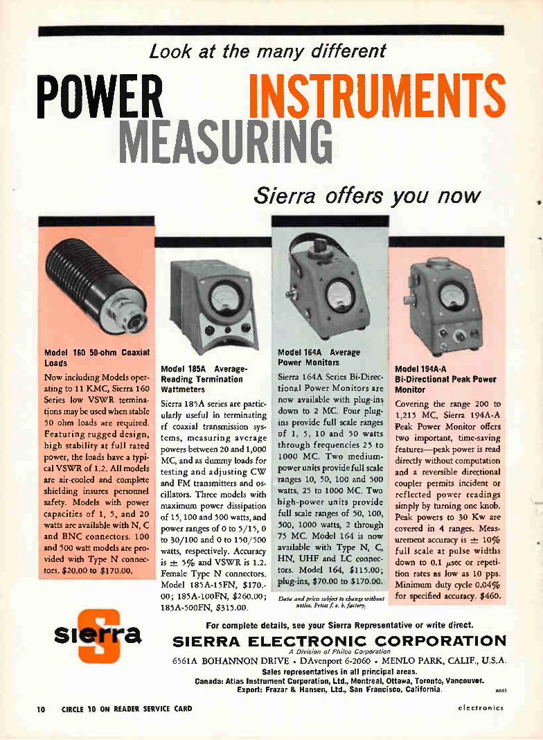
Model 160 50-ohm Coaxial Loads
Now including Models oper-
ating to 11 KMC, Sierra 160
Series low VSWR termina-
tions may be used when stable
50 ohm loads are required.
Featuring rugged design,
high stability at full rated
power, the loads have a typi-
cal VSWR of 1.2. All models
are air-cooled and complete shielding insures personnel
safety. Models with power
capacities of 1, 5, and 20
watts are available with N, C
and BNC connectors. 100
and 500 watt models are pro-
vided with Type N connec-
tors. $20.00 to $170.00.
dre sierra
Model 185A Average-Reading Termination Wattmeters
Sierra 185A series are partic-
ularly useful in terminating
rf coaxial transmission sys-
tems, measuring average
powers between 20 and 1,000
MC, and as dummy loads for
testing and adjusting CW
and FM transmitters and os-
cillators. Three models with
maximum power dissipation
of 15, 100 and 500 watts, and
power ranges of 0 to 5/15, 0
to 30/100 and 0 to 150/500
watts, respectively. Accuracy
is -4- 5% and VSWR is 1.2.
Female Type N connectors.
Model 185A-15FN, $170.-
00; 185A-100FN, $260.00;
185A-500FN, $315.00.
Model 164A Average Power Monitors
Sierra 164A Series Bi-Direc-
tional Power Monitors are now available with plug-ins
down to 2 MC. Four plug-
ins provide full scale ranges
of 1, 5, 10 and 50 watts
through frequencies 25 to
1000 MC. Two medium-
power units provide full scale
ranges 10, 50, 100 and 500
watts, 25 to 1000 MC. Two
high-power units provide
full scale ranges of 50, 100,
500, 1000 watts, 2 through
75 MC. Model 164 is now available with Type N, C,
HN, UHF and LC connec-
tors. Model 164, $115.00;
plug-ins, $70.00 to $170.00.
Data and prices subject to change without notice. Prices f o. b. factory.
Model 194A-A Bi-Directional Peak Power Monitor
Covering the range 200 to
1,215 MC, Sierra 194A-A
Peak Power Monitor offers two important, time-saving
features—peak power is read
directly without computation
and a reversible directional coupler permits incident or
reflected power readings
simply by turning one knob.
Peak powers to 30 Kw are
covered in 4 ranges. Meas-
urement accuracy is -+- 10%
full scale at pulse widths
down to 0.1 ,u,sec or repeti-
tion rates as low as 10 pps.
Minimum duty cycle 0.04% for specified accuracy. $460.
For complete details, see your Sierra Representative or write direct.
SIERRA ELECTRONIC CORPORATION A Division of Phi/co Corporation
6561A BOHANNON DRIVE • DAvenport 6-2060 • MENLO PARK, CALIF., U.S.A. Sales representatives in all principal areas.
Canada: Atlas Instrument Corporation, Ltd., Montreal, Ottawa, Toronto, Vancouver. Export: Frazar & Hansen, Ltd., San Francisco, California.
10 CIRCLE 10 ON READER SERVICE CARD electronics
ELECTRONICS NEWSLETTER Seek Ray to Disarm
Nuclear Warheads
MICROWAVES, infrared, atomic par-ticles and X-rays are under con-sideration as energy media for a "death-ray" to destroy incoming missiles. Varo Mfg., Garland, Tex., is one firm working on the secret project for Department of Defense, has reportedly proved the feasibil-ity of using microwave energy to abort missile missions.
Defense scientists say they don't want to burn the missile up, but merely to create a chemical or physical change to render atomic warheads harmless (see ELEC-
TRONICS, p 36, May 13). In other developments: Boeing copped a $247-million
contract for R&D on Minuteman solid-fueled ICBM, making definite an earlier letter contract.
ITT's Federal Electric Corp. takes over operation and mainte-nance of the 60 Dew-line radar warning stations under $40.8-mil-lion USAF contract. RCA Service Co. will take over
management of the USAF Alaskan long lines system (White Alice) under a $5.3-million contract. Magnavox will develop new
radars and radar indicators for Bureau of Naval Weapons. Classi-fied contracts total $32.5 million.
Survey Suggests Research
Is Key to Growth
RECENT SURVEY of small and middle-sized electronics firms indicates the need to develop new products and processes to maintain growth. The survey was taken by an in-
vestment firm, covered 25 com-panies responsible for about a third of total electronics industry sales in 1958. It was conducted with the idea of obtaining, for a series of years, R&D statistics for purely electronics companies comparable to standard indices of capital ex-penditures and sales.
Sales of the 25 companies in-creased 36 percent between 1955 and 1958, as compared with an 11-percent rise for the electronics in-dustry as a whole during the same
period. Research and development spending consistently exceeded out-lays for capital equipment by about 50 percent.
Capital expenditures were prac-tically the same in 1958 as in 1957 (averaging 6 percent of sales) ; the percentage is rising slowly. Ex-penditures for research and devel-opment increased yearly and topped 9 percent of sales in 1958. Esti-mated R&D spending level for 1960 is over 10 percent of sales.
Journeyman Test Will Use
Miniature Telemeter
MINIATURE TELEMETERING SYSTEM
designed by Space Electronics Corp., Glendale, Calif., will be used by Air Force in forthcoming flight of the Journeyman sounding rocket. The system, called Digilock, will
telemeter data on radiation and other phenomena during the entire 15-hour flight, coming into opera-tion three minutes after the nose cone separates.
Circuits occupy a total volume of 54 cu in., consist of a 250-mw transmitter weighing half a pound, coding unit weighing one and a half pounds. Total power drain from the 11-lb power pack is 31 w. System is designed to handle mul-
tiple-signal analog or digital data electronically commutated by the encoder. Rate of data transmission will be either 64 or 256 bits a second, depending on requirements.
System Gives Commanders
Precise Position Data
BATTLEFIELD POSITION-fixing and navigation system that will enable a field commander to keep track of all his units, including aircraft, ground vehicles and foot soldiers, will be built for Army by Bendix. The system comprises a chain of
four ground-based transmitting stations, mobile receivers, and a chart construction and reproduction unit. Transmitting chain com-prises a master and three slave stations, all on different fre-quencies.
Lightweight, accurate system op-erates in the 1-f portion of the spec-
trum, can be set up and in operation within five hours. Using hyper-bolic techniques, the equipment can cover a 150,000-sq-mi area, oper-ates day or night in all weather. Receivers are designed for use by foot soldiers, vehicles on either ground or water, and fixed or rotary-wing aircraft plus any num-ber of receivers.
European Tv Sets Use
U.S.-Made Picture Tubes
SEVERAL EUROPEAN tv-setmakers are putting Sylvania 23-in, bonded-shield tv picture tubes on their new equipment. Companies in-volved in the deal are located in Germany, Italy, France, England and Scandinavia. In the past, Euro-pean companies have mostly manu-factured their own tubes, or used European makes, for reasons of economy and ease of replacement.
Sylvania exported 25,000 tubes last month for a dollar value of $970,000. Company reports indicate that a similar number will be shipped this month, with dollar value expected to exceed $1 million. One company puts Sylvania picture tubes on a Japanese chassis.
Airport Radars Use
Coherent MTIs
AIRPORT SURVEILLANCE radars de-signed by Texas Instruments will be installed at 34 airports during the next year and a half. The radars have a range of 60 miles, can reach an altitude of 25,000 ft at maximum range, will help Federal Aviation Agency keep abreast of the jet age.
TI's ASR-4 can operate either normally or with a coherent mov-ing-target indicator system, as the controller chooses. Coherent oscil-lator serves as reference against which returns are compared; identical returns cancel out. Stag-gered pulse-repetition frequency prevents the cancellation of targets flying at blind speed (the speed at which a target, between successive pulses, moves a distance correspond-ing to a multiple of the transmitter wavelength). On conventional mti's, a target moving at blind speed reflects an in-phase pulse which is cancelled.
July 22, 1960 11
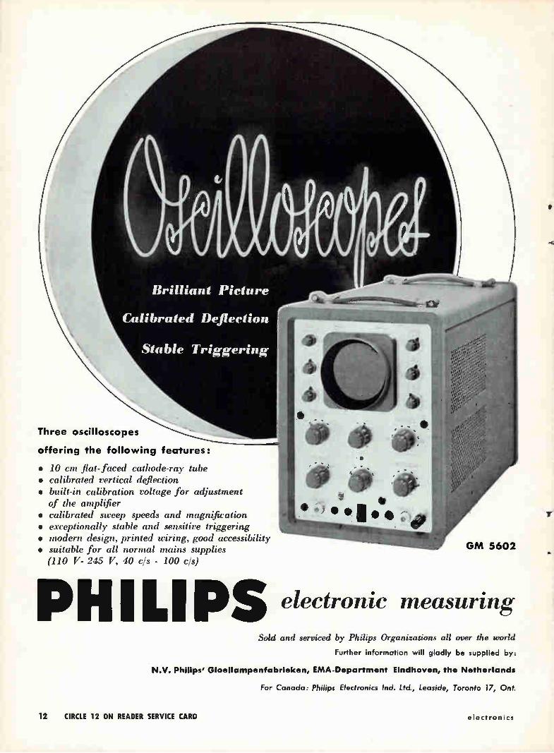
Brilliant Picture
Calibrated Deflection
Stable Triggering,
Three oscilloscopes
offering the following features:
• 10 cm flat- faced cathode-ray tube • calibrated vertical deflection • built-in calibration voltage for adjustment
of the amplifier • calibrated sweep speeds and magnification • exceptionally stable and sensitive triggering • modern design, printed wiring, good accessibility • suitable for all normal mains supplies
(110 V- 245 V, 40 cls - 100 cls)
GM 5602
ILIPS electronic measuring Sold and serviced by Philips Organizations all over the world
Further information will gladly be supplied by:
N.V. Philips' Gloeilampenfabrieken, EMA-Department Eindhoven, the Netherlands
For Canada: Philips Electronics Ind. Ltd., Leoside, Toronto 17, Ont.
12 CIRCLE 12 ON READER SERVICE CARD electronics
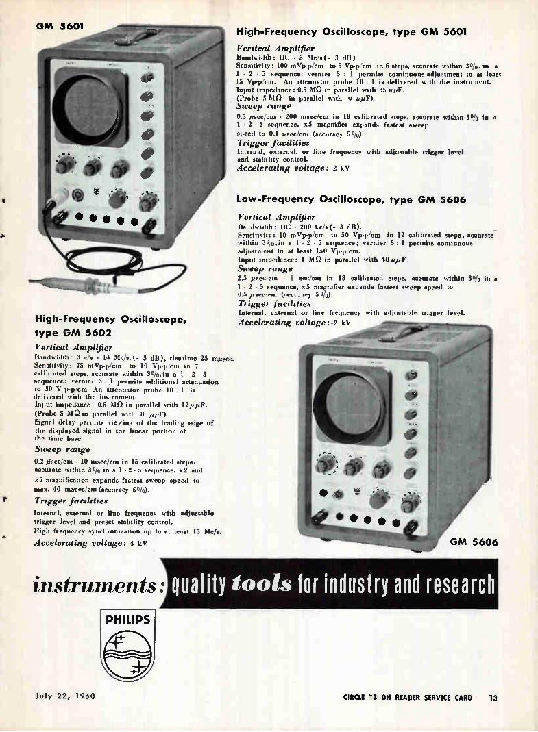
High-Frequency Oscilloscope,
type GM 5602
Vertical Amplifier Bandwidth: 3 c/s - 14 Mc/s,(- 3 dB), risetime 25 mpsec. Sensitivity: 75 mVp•p/cm to 10 Vp•p'cm in 7 calibrated steps, accurate within 30/0,in a 1 • 2 • 5 sequence; vernier 3 : 1 permits additional attenuation to 30 V p-p/cm. An attenuator probe 10 : 1 is delivered with the instrument. Input impedance: 0.5 MO in parallel with 12ppF. (Probe 5 MO in parallel with 8 ppF). Signal delay permits viewing of the leading edge of the displayed signal in the linear portion of the time base.
Sweep range
0.2 pkec/cm • 10 maec/cm in 15 calibrated steps, accurate within 30/0 in a 1 - 2 • 5 sequence, x2 and
x5 magnification expands fastest sweep speed to max. 40 mpsec/cm (accuracy 50/0).
Trigger facilities
Internal, external or line frequency with adjustable trigger level and preset stability control.
High frequency synchronization up to at least 15 Mc/s.
Accelerating voltage: 4 kV •
1 instruments:
High-Frequency Oscilloscope, type GM 5601
Vertical Amplifier Bandwidth: DC - 5 Mc's ( - 3 dB). Sensitivity: 100 mVp-p/cm to 5 Vp.p 'cm in 6 steps, accurate within 30/0,in a 1 - 2 - 5 sequence; vernier 3 : 1 permits continuous adjustment to at least 15 Vp-ptcm. An attenuator probe 10 : 1 is delivered with the instrument. Input impedance: 0.5 MO in parallel with 35 pe. (Probe 5 MO in parallel with 9 ppF). Sweep range 0.5 peec/cm - 200 mece/cm in 18 calibrated steps, accurate within 30/e in a 1 • 2 • 5 sequence, x5 magnifier expands fastest sweep speed to 0.1 psec/cm (accuracy 50/0). Trigger facilities Internal, external, or line frequency with adjustable trigger level and stability control. Accelerating voltage: 2 kV
Low-Frequency Oscilloscope, type GM 5606
Vertical Amplifier Bandwidth: DC • 200 kc/s(- 3 dB). Sensitivity: 10 mVp-p/cm to 50 Vp-p/cm in 12 calibrated steps, accurate within 3olo,in a 1 - 2 • 5 sequence; vernier 3 : 1 permits continuous adjustment to at least 150 Vp-pena. Input impedance: 1 MO in parallel with 40 itpF
Sweep range 2.5 psec/cm • 1 sec/cm in 18 calibrated steps, aceurate within 30/0 in a 1 - 2 • 5 sequence, x5 magnifier expands fastest sweep speed to 0.5 p sec /em (accuracy 5 0/0).
Trigger facilities Internal, external or line frequency with adjustable trigger level.
Accelerating voltage:.2 kV
GM 5606
44 Quality Cools for industry and research
July 22, 1960 CIRCLE 13 ON READER SERVICE CARD 13
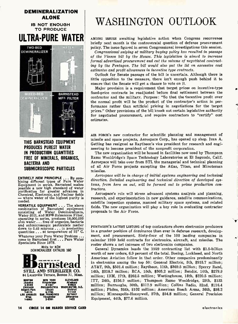
DEMINERALIZATION ALONE
IS NOT ENOUGH TO PRODUCE
ULTRA-PURE WATER
DEMINERALIZER
THIS BARNSTEAD EQUIPMENT PRODUCES PUREST WATER IN PRODUCTION QUANTITIES FREE OF MINERALS, ORGANICS, BACTERIA AND SUBMICROSCOPIC PARTICLES
ENTIRELY NEW PRINCIPLE .. . By com-bining different types of Pure Water Equipment in series, Barnstead makes possible a new high standard of water purification for greater advances in Chemical, Electronic, and Nuclear fields — where water of the highest purity is needed. VERSATILE EQUIPMENT . .. The above combination of Barnstead equipment consisting of Water Demineralizers, Water Still, and MF® Submicron Filter, operating in series, produces 18,000,000 ohm water .... free of organics, bacteria and submicroscopic particulate matter down to 0.45 microns . . . in production quantities . .. at temperature of 25° C. Whatever your Pure Water Problem ... come to Barnstead first.. . Pure Water Specialists Since 1878.
Write for NEW DEMINERALIZER CATALOG 160
a—r-ris-tead STILL AND STERILIZER CO. 81 Lanesville Terrace, Boston 31, Mass.
BOSTON NEW YORK JAmaica Kingsbridge 2.8490 8-1557 CHICAGO PHILADELPHIA
ROgers Park LOcust 1-6173 8-1796
LOS ANGELES SAN FRANCISCO RYan TEmplebar
1-6663 2-5391
CLEVELAND ACademy 6-6622
WASHINGTON, D.C. District 7-1142 DETROIT
ENterprise 7422
WASHINGTON OUTLOOK
AMONG ISSUES awaiting legislative action when Congress reconvenes briefly next month is the controversial question of defense procurement policy. The issue figured in seven Congressional investigations this session.
Congressional sniping at military buying policy has resulted in passage of the Vinson bill by the House. This legislation is aimed to increase formal advertised procurement and cut the volume of negotiated contract-ing by the Pentagon. The bill would also put the lid on excessive cost estimates and profit allowances in incentive type contracts.
Outlook for Senate passage of the bill is uncertain. Although there is little opposition to the measure, there isn't enough push behind it to ensure that the Senate will get a chance to vote on it. Major provision is a requirement that target prices on incentive-type
fixed-price contracts be readjusted before final settlement between the contractor and the military. Purpose: "So that the 'incentive profit over the normal profit will be the product of the contractor's action in per-formance rather than artificial pricing in negotiations for the target prices." Other provisions of the bill knock out certain legislative authority for negotiated procurement, and require contractors to "certify" cost estimates.
AIR FORCE'S new contractor for scientific planning and management of missile and space projects, Aerospace Corp., has opened up shop. Ivan A. Getting has resigned as Raytheon's vice president for research and engi-neering to become president of the nonprofit corporation. The new organization will be housed in facilities now used by Thompson
Ramo Wooldridge's Space Technology Laboratories at El Segundo, Calif. Aerospace will take over from STL the managerial and technical planning of all Air Force projects excepting the Atlas, Titan, and Minuteman missiles.
Aerospace will be in charge of initial systems engineering and technical direction. Detailed engineering and technical direction of developed sys-tems, from here on out, will be farmed out to prime production con-tractors.
Aerospace's role will stress advanced systems analysis and planning, research, and experimentation in new guidance, satellite communications, satellite inspection systems, manned military space systems, and related fields. The new organization will play a key role in evaluating contractor proposals to the Air Force.
PENTAGON'S LATEST LISTING of top contractors shows electronics producers in a greater position of dominance than ever in defense research, develop-ment, and procurement. Sixty-four of the 100 leading companies in calendar 1959 held contracts for electronics, aircraft, and missiles. The roster shows a net increase of two electronics companies.
General Dynamics heads the 1959 contracting list with $1.5-billion worth of new orders, 6.9 percent of the total. Boeing, Lockheed, and North American Aviation follow in that order. Other companies predominantly in electronics among the top 50: General Electric, 5th, $915.7 million; AT&T, 9th, $501.4 million; Raytheon, 11th, $369.5 million; Sperry Rand, 14th, $318.7 million; RCA, 15th, $303.2 million; Bendix, 16th, $279.9 million; IBM, 17th, $262.5 million; Westinghouse, 18th, $220.5 million; ITT, 24th, $156.9 million; Thompson Ramo Wooldridge, 29th, $133 million; Burroughs, 30th, $117.9 million; Collins Radio, 32nd, $116.4 million; Philco, 35th, $102 million; American Bosch Arma, 36th, $98.2 million; Minneapolis-Honeywell, 37th, $94.8 million; General Precision Equipment, 44th, $77.6 million.
us.
4
14 CIRCLE 14 ON READER SERVICE CARD electronics
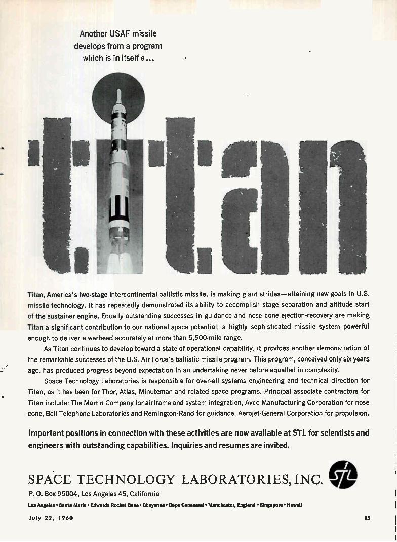
Another USAF missile
develops from a program
which is in itself a...
Titan, America's two-stage intercontinental ballistic missile, is making giant strides—attaining new goals in U.S.
missile technology. It has repeatedly demonstrated its ability to accomplish stage separation and altitude start
of the sustainer engine. Equally outstanding successes in guidance and nose cone ejection-recovery are making
Titan a significant contribution to our national space potential; a highly sophisticated missile system powerful
enough to deliver a warhead accurately at more than 5,500-mile range.
As Titan continues to develop toward a state of operational capability, it provides another demonstration of
the remarkable successes of the U.S. Air Force's ballistic missile program. This program, conceived only six years
ago, has produced progress beyond expectation in an undertaking never before equalled in complexity.
Space Technology Laboratories is responsible for over-all systems engineering and technical direction for
Titan, as it has been for Thor, Atlas, Minuteman and related space programs. Principal associate contractors for
Titan include: The Martin Company for airframe and system integration, Avco Manufacturing Corporation for nose
cone, Bell Telephone Laboratories and Remington-Rand for guidance, Aerojet-General Corporation for propulsion.
Important positions in connection with these activities are now available at SIL for scientists and
engineers with outstanding capabilities. Inquiries and resumes are invited.
SPACE TECHNOLOGY LABORATORIES, INC. P. 0. Box 95004, Los Angeles 45, California
Los Angeles • Santa Maria • Edwards Rocket Base • Cheyenne • Cape Canaveral • Manchester, England • Singapore • Hawaii
July 22, 1960 15
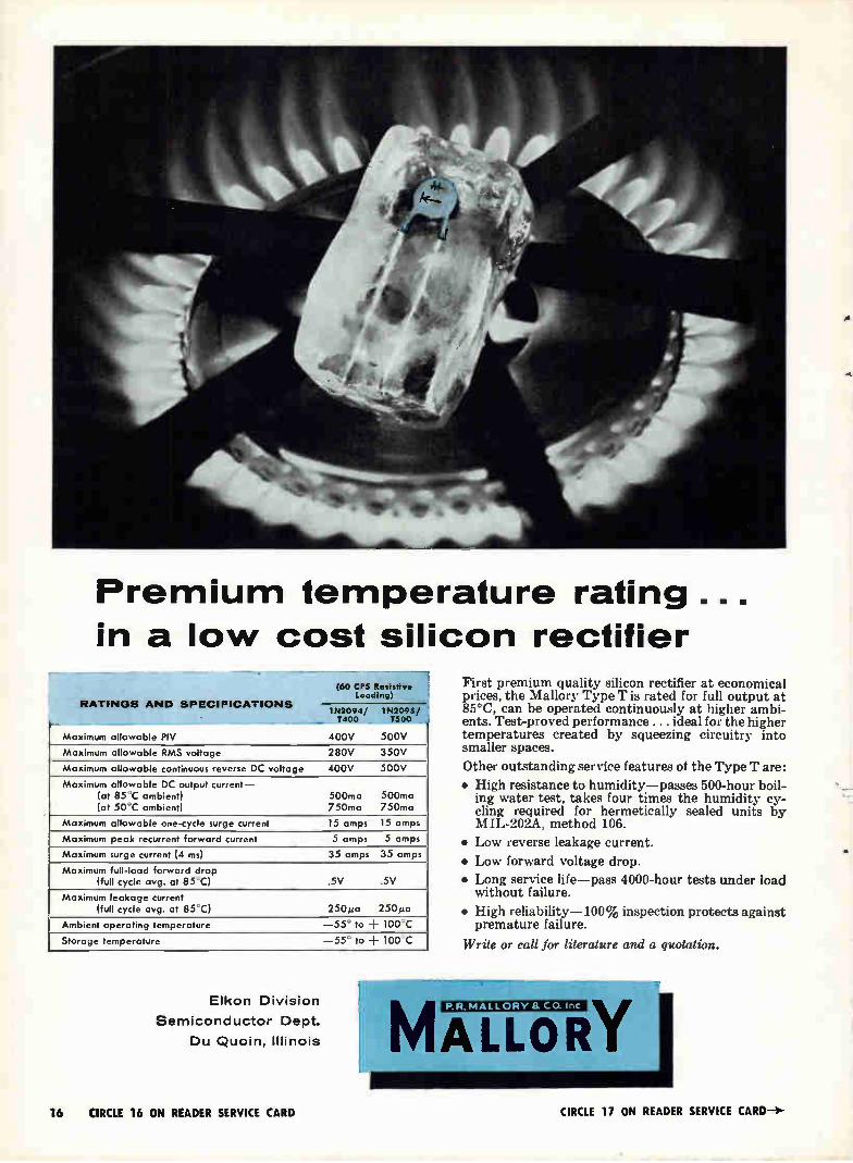
Premium temperature rating ...
in a low cost silicon rectifier
RATINGS AND SPECIFICATIONS
(60 CPS Resistive boding)
11.42094/ 1N2095/ 400 T500 ---
Maximum allowable PIV 400V 500V
Maximum allowable RMS voltage 280V 350V
Maximum allowable continuous reverse DC voltage 400V 500V
Maximum allowable DC output current— (at 85 C ambient) (at 50'C ambient)
500ma 500ma 750ma 750ma
Maximum allowable one-cycle surge current 15 amps 15 amps
Maximum peak recurrent forward current 5 amps 5 amps
Maximum surge current (4 ms) 35 amps 35 amps
Maximum full-load forward drop (full cycle avg. at 85 C) .5V .5V
Maximum leakage current (full cycle avg. at 85 °C) 250µa 250µa
Ambient operating temperature —55 ° to + 100 C
Storage temperature —55 ° to -I- 100 C
Elkon Division
Semiconductor Dept.
Du Quoin, Illinois
First premium quality silicon rectifier at economical prices, the Mallory Type T is rated for full output at 85°C, can be operated continuously at higher ambi-ents. Test-proved performance. .. ideal for the higher temperatures created by squeezing circuitry into smaller spaces.
Other outstanding service features of the Type T are:
• High resistance to humidity—passes 500-hour boil-ing water test, takes four times the humidity cy-cling required for hermetically sealed units by MIL-202A, method 106.
• Low reverse leakage current.
• Low forward voltage drop.
• Long service life—pass 4000-hour tests under load without failure.
• High reliability-100% inspection protects against premature failure.
Write or call for literature and a quotation.
P. R. MALLORY /I CO. Inc.
MALLORY 16 CIRCLE 16 ON READER SERVICE CARD CIRCLE 17 ON READER SERVICE CARD—)-
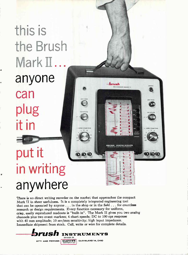
this ¡s the Brush Mark II... anyone can plug ¡it in
put ¡t , in writing
anywhere
vorte / chart an.
5 2
RECORDER MARK II
BRIM» INISTAIIIIIIIEN11911 OP
Cha,1
epee d
There is no direct writing recorder on the market that approaches the compact Mark II in sheer usefulness. It is a completely integrated engineering tool that can be operated by anyone . . . in the shop or in the field . . . for countless research or design requirements. Every function necessary for uniform, crisp, easily reproduced readouts is "built-in". The Mark II gives you two analog channels plus two event markers; 4 chart speeds; DC to 100 cps response with 40 mm amplitude; 10 mv/mm sensitivity; high input impedance. Immediate shipment from stock. Call, write or wire for complete details.
brush IN suqauluENT-rs
• volts /chart hne
2
5
off
371*. ANO PERKINS
DIVISION OF
CLEVITE C OOOOOO TION
CLEVELAND 14, OHIO
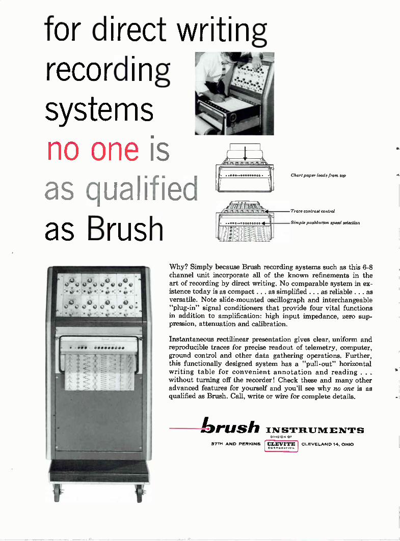
for direct writing recording systems no one is as qualified as Brush
O 43 00 QQ(.1talà4)00
O 0 0 • Q043 0 43o Q430.
• •600• Chart paper loads from top
41--Trace contrast control
Simple pushbutton speed selection
Why? Simply because Brush recording systems such as this 6-8 channel unit incorporate all of the known refinements in the art of recording by direct writing. No comparable system in ex-istence today is as compact . . . as simplified. .. as reliable . . . as versatile. Note slide-mounted oscillograph and interchangeable "plug-in" signal conditioners that provide four vital functions in addition to amplification: high input impedance, zero sup-pression, attenuation and calibration.
Instantaneous rectilinear presentation gives clear, uniform and reproducible traces for precise readout of telemetry, computer, ground control and other data gathering operations. Further, this functionally designed system has a "pull-out" horizontal writing table for convenient annotation and reading . . . without turning off the recorder! Check these and many other advanced features for yourself and you'll see why no one is as qualified as Brush. Call, write or wire for complete details.
brush INSTRum E NTs 37TH AND PERKINS
DIVISION OF
CLEVITE COMPOR•TiON
CLEVELAND 14, OHIO
.4
•
Vol. 2, No. 2 Nickelonic News DEVELOPMENTS IN NICKEL
AND NICKEL ALLOYS AND THEIR APPLICATIONS
Grade "A" Nickel bus bar keeps molten metals flowing
at 1000 -1600 F
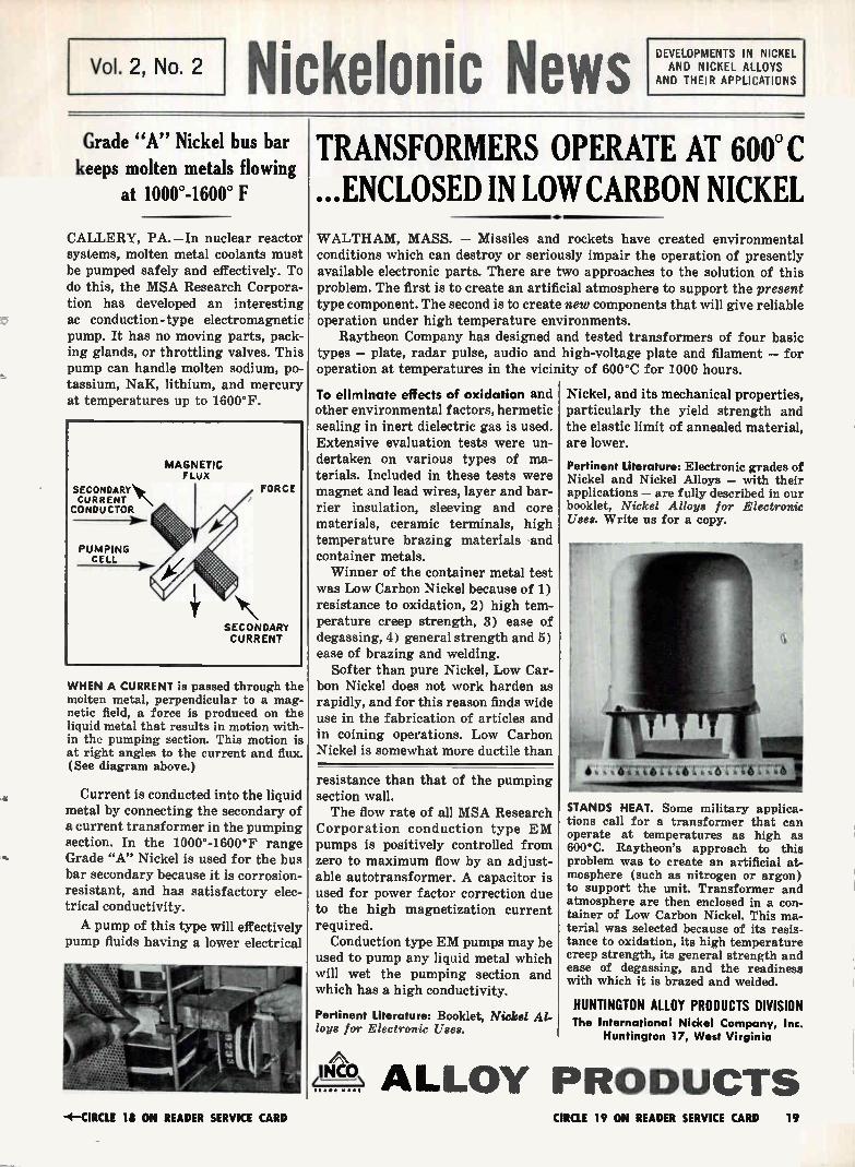
CALLERY, PA.—In nuclear reactor systems, molten metal coolants must be pumped safely and effectively. To do this, the MSA Research Corpora-tion has developed an interesting ac conduction-type electromagnetic pump. It has no moving parts, pack-ing glands, or throttling valves. This pump can handle molten sodium, po-tassium, NaK, lithium, and mercury at temperatures up to 1600°F.
WHEN A CURRENT is passed through the molten metal, perpendicular to a mag-netic field, a force is produced on the liquid metal that results in motion with-in the pumping section. This motion is at right angles to the current and flux. (See diagram above.)
Current is conducted into the liquid metal by connecting the secondary of a current transformer in the pumping section. In the 1000°-1600°F range Grade "A" Nickel is used for the bus bar secondary because it is corrosion-resistant, and has satisfactory elec-trical conductivity.
A pump of this type will effectively pump fluids having a lower electrical
TRANSFORMERS OPERATE AT 600° C ...ENCLOSED IN LOW CARBON NICKEL
•
WALTHAM, MASS. — Missiles and rockets have created environmental conditions which can destroy or seriously impair the operation of presently available electronic parts. There are two approaches to the solution of this problem. The first is to create an artificial atmosphere to support the present type component. The second is to create new components that will give reliable operation under high temperature environments.
Raytheon Company has designed and tested transformers of four basic types — plate, radar pulse, audio and high-voltage plate and filament — for operation at temperatures in the vicinity of 600°C for 1000 hours.
To eliminate effects of oxidation and other environmental factors, hermetic sealing in inert dielectric gas is used. Extensive evaluation tests were un-dertaken on various types of ma-terials. Included in these tests were magnet and lead wires, layer and bar-rier insulation, sleeving and core materials, ceramic terminals, high temperature brazing materials and container metals. Winner of the container metal test
was Low Carbon Nickel because of 1) resistance to oxidation, 2) high tem-perature creep strength, 3) ease of degassing, 4) general strength and 5) ease of brazing and welding.
Softer than pure Nickel, Low Car-bon Nickel does not work harden as rapidly, and for this reason finds wide use in the fabrication of articles and in coining operations. Low Carbon Nickel is somewhat more ductile than
resistance than that of the pumping section wall. The flow rate of all MSA Research
Corporation conduction type EM pumps is positively controlled from zero to maximum flow by an adjust-able autotransformer. A capacitor is used for power factor correction due to the high magnetization current required.
Conduction type EM pumps may be used to pump any liquid metal which will wet the pumping section and which has a high conductivity.
Pertinent Literature: Booklet, Nickel Al-loys for Electronic Uses.
Nickel, and its mechanical properties, particularly the yield strength and the elastic limit of annealed material, are lower.
Pertinent Literature: Electronic grades of Nickel and Nickel Alloys — with their applications — are fully described in our booklet, Nickel Alloys for Electronic Uses. Write us for a copy.
411'141T111";:rell't
STANDS HEAT. Some military applica-tions call for a transformer that can operate at temperatures as high as 600°C. Raytheon's approach to this problem was to create an artificial at-mosphere (such as nitrogen or argon) to support the unit. Transformer and atmosphere are then enclosed in a con-tainer of Low Carbon Nickel. This ma-terial was selected because of its resis-tance to oxidation, its high temperature creep strength, its general strength and ease of degassing, and the readiness with which it is brazed and welded.
HUNTINGTON ALLOY PRODUCTS DIVISION The International Nickel Company, Inc.
Huntington 17, West Virginia
je-\\c3 ALLOY PRODUCTS -4— CIRCLE 18 ON READER SERVICE CARD CIRCLE 19 ON READER SERVICE CARD 19
MAX. ERROR
2
o 1
2
3
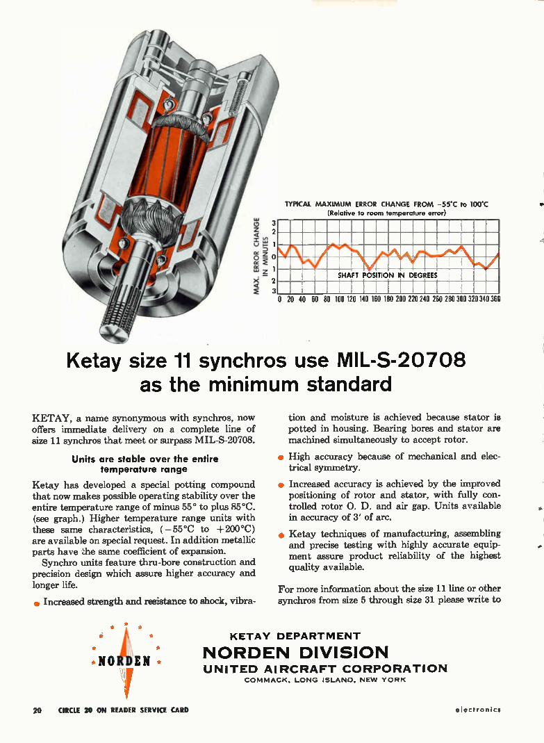
TYPICAL MAXIMUM ERROR CHANGE FROM -55'C to 100C (Relative to room temperature error)
SHAFT POSITION IN DEGREES
i 0 20 40 60 80 100 120 140 160 180 200 220 240 260 280 300 320 340 360
Ketay size 11 synchros use MIL-S-20708 as the minimum standard
KETAY, a name synonymous with synchros, now offers immediate delivery on a complete line of size 11 synchros that meet or surpass MIL-S-20708.
Units are stable over the entire temperature range
Ketay has developed a special potting compound that now makes possible operating stability over the entire temperature range of minus 55° to plus 85°C. (see graph.) Higher temperature range units with these same characteristics, ( — 55°C to +200°C) are available on special request. In addition metallic parts have ;:he same coefficient of expansion. Synchro units feature thru-bore construction and
precision design which assure higher accuracy and longer life.
e Increased strength and resistance to shock, vibra-
NORDEN
tion and moisture is achieved because stator is potted in housing. Bearing bores and stator are machined simultaneously to accept rotor.
e High accuracy because of mechanical and elec-trical symmetry.
• Increased accuracy is achieved by the improved positioning of rotor and stator, with fully con-trolled rotor O. D. and air gap. Units available in accuracy of 3' of arc.
• Ketay techniques of manufacturing, assembling and precise testing with highly accurate equip-ment assure product reliability of the highest quality available.
For more information about the size 11 line or other synchros from size 5 through size 31 please write to
KETAY DEPARTMENT
NORDEN DIVISION UNITED AIRCRAFT CORPORATION
COMMACK, LONG ISLAND, NEW YORK
20 CIRCLE 20 ON READER SERVICE CARD electronics
FINANCIAL ROUNDUP
Varian Sales Up 27% in First Half
SALES INCREASE of 27 percent and earnings rise of 25 percent are re-ported by Varian Associates, Palo Alto, Calif., for first half of fiscal
1960 as compared with the similar period of 1959. Sales for the pe-riod were $22,022,715, up from $17,378,142. Net income was $1,-398,605 or 45 cents a share on 3,134,204 shares outstanding. This compares with $1,112,530, or 36
cents a share on 3,134,204 shares oustanding in the same period of 1959. Order backlog for the period ended April 2, 1960, was in excess of $23 million.
Fischer & Porter Co., Warminster, Pa., reports highest sales and ship-ments in company history and earnings double those of the past year for the fiscal period ended April 30, 1960. Sales this year were $17,120,000, as compared with 1959's $15,353,000. Net profit for 1960 was $306,250, and for 1959, $165,876. Per-share earnings for the 1959 total were 37 cents, as compared with 85 cents this year.
Taylor Instrument Co., Rochester, N. Y., in making its nine-month
report for the period ended April 30, 1960, discloses net income of $1,240,642, per-share earnings of $3.13, working capital of $11.303,-605. For the comparable period of 1959, the figures are net income of $408,360, per-share earnings of $1.03, working capital of $10,754,-000. Orders for 1960 period in-creased 9.4 percent over last year and sales rose 13.1 percent.
Collins Radio, Cedar Rapids, Ia., for the nine months ended April 30, 1960, reports earnings of $5,-901,605 on consolidated sales of $138,991,830 stated without audit and subject to year-end adjust-ments. This represents $2.96 per share on 1,983,194 shares out-standing. A total of 169,847 com-
mon shares were issued during the period, largely from conversion of preferred stock and debentures.
Figures for the comparable 1959
periód: Earnings of $2,050,509 on sales of $78,069,658 representing per-share earnings of 95 cents.
Lindly & Co., Mineola, N. Y., man-ufacturer of electronic automatic control equipment for the textile industry, announces net sales for the first quarter of 1960 rose 29 percent over those of 1959's first
quarter. Total sales for 1960 are expected to reach about $600,000, as compared with the 1959 total of $459,000.
Specialty Electronics, Syosset,
N. Y., reveals sales of $3,578,946
for the nine-month period ended April 30, 1960, resulting in per-tax
income of $323,734 and net of $151,334. In the fiscal year ended July 31, 1959, net sales were $1,-567,000, income before taxes was $114,000 and net income was $102,-000. The company was formed in May of 1959, so nine-month fig-ures are not available for last year.
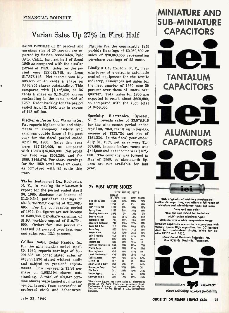
25 MOST ACTIVE STOCKS WEEK ENDING JULY 8
SHARES (IN 100's) HIGH LOW CLOSE
Gen Tel & El« 1,548 301/4 28% 293/4 RCA 1,199 66 63 64% Int'l Tel & Tel 1,179 423/4 393/8 423/8 Sperry Rand 1,146 251/4 241/2 241/4 Sterling Precision 1,061 33/4 33/o 3% Bulova Watch 821 20% 181/4 19% Victoreen last 797 151/2 13% 141/2 Standard Kollsman 737 26% 22% 237/e Amer Tel & Tel 716 90% 891/4 90% Anca Corp 620 151/2 141/4 141/4 Ampex Corp 617 401/2 381/4 381,4 Univ Controls 616 18% 171/4 171/4 Gen Inst 605 491/4 43 45 Teletro Ind 589 161/4 131/4 16 Hoffman Electronics 554 301,4 26% 271/4 Philco Corp 459 291/4 27% 281/2 Westinghouse 458 591/4 571/4 59 Loral Electronics 439 981/2 75% 771/4 Collins Radio 407 731,4 661% 673/4 Litton Ind 407 96 85 86% Amer Mach & Fdry 399 671,4 63 64% Burroughs Corp 396 371/4 343/4 36 Edo Corp 381 243/4 211/2 21% Varian Assoc 311 64 57 593/4 Emerson Radio 280 173/4 15% 163/8
The above figures represent sales of electronics stocks on the New York and American Stock Exchanges. Listings are pi-mated exclusively for ELECTRONICS by Ira Haupt & Co., investment bankers.
MINIATURE AND SUB-MINIATURE CAPACITORS
TANTALUM CAPACITORS
• •
ALUMINUM CAPACITORS
• •
1 lei, originator of miniature aluminum foil
electrolytic capacitors, now offers a full range of miniature and sub-miniature types and sizes:
Polar and non-polar
Plain foil and etched foil tantalums
Multi-section aluminum types
Reliable over a wide temperature range
Tantalum capacitors are made in accordance with Military Specs. High capacities, low DC leakage deal for transistorized circuits. Write for bul-letins 81558 and 2625.
International Electronic Industries, Inc. Box 9036-Q Nashville, Tennessee.
• •
11 AN 11105 COMPANY
where reliability replaces probability
July 22, 1960 CIRCLE 21 ON READER SERVICE CARD 21
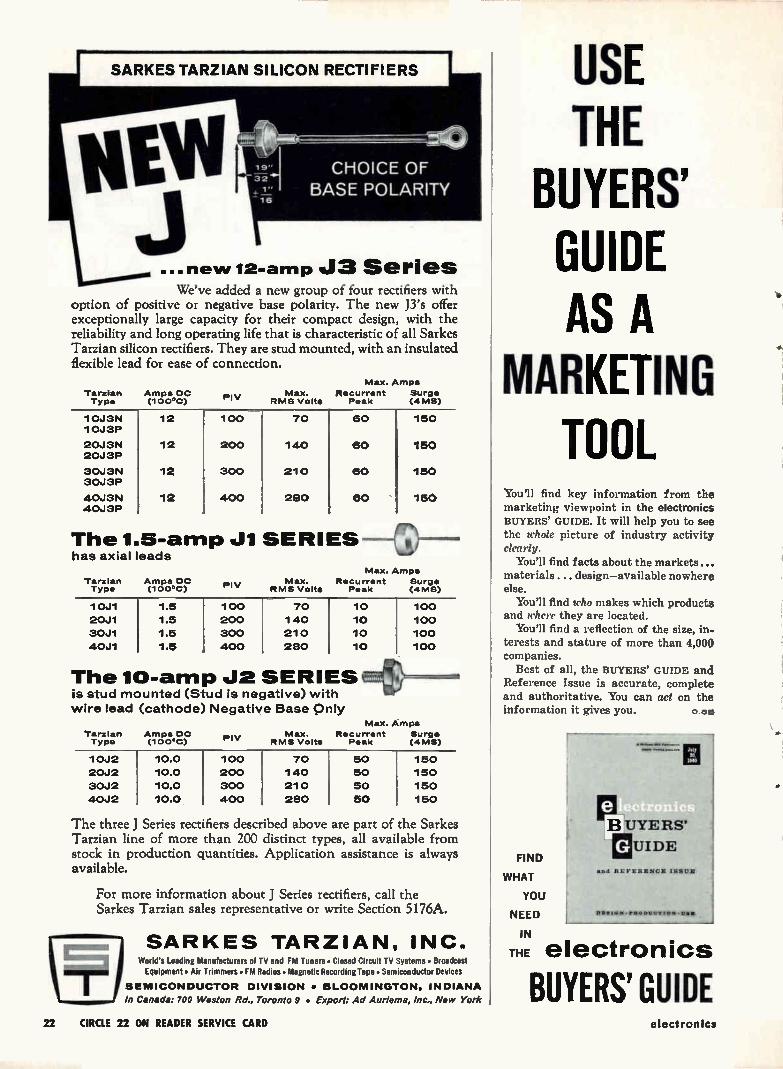
... new 12-amp J3 Series We've added a new group of four rectifiers with
option of positive or negative base polarity. The new J3's offer exceptionally large capacity for their compact design, with the reliability and long operating life that is characteristic of all Sarkes Tarzian silicon rectifiers. They are stud mounted, with an insulated flexible lead for ease of connection.
Tarzian Type
Amps DC (100'C)
Ply
Max. Amps
Max. Recurrent Surge RMS Volts Peak (4MS)
10J3N 10J3P
12 100 70 60 150
20J3N 20J3P
12 200 140 60 150
30J3N 30J3P
12 300 210 60 150
40J3N 40J3P
12 400 280 60 150
The 1.5-amp J1 SERIES has axial leads
Tarzian Type
Amps DC (100°C) Ply
Max. Amps
Max. Recurrent Surge RMS Volte Peak (4MS)
10J1 1.5 100 70 10 100
20J1 1.5 200 140 10 100
30J1 1.5 300 210 10 100
40J1 1.5 400 280 10 100
The 10-amp J2 SERIES is stud mounted (Stud is negative) with
wire lead (cathode) Negative Base Only
Tarzian Type
Amps DC (100°C) Ply
Max. RMS Volts
Max. Amps
Recurrent Surge Peak (4MS)
10J2 10.0 100 70 50 150
20J2 10.0 200 140 50 150
30J2 10.0 300 210 50 150
40J2 10.0 400 280 50 150
The three J Series rect fiers described above are part of the Sarkes Tarzian line of more than 200 distinct types, all available from stock in production quantities. Application assistance is always available.
For more information about J Series rectifiers, call the Sarkes Tarzian sales representative or write Section 5176A.
SARIKES TARZIAN, INC. World's Leading Manufacturers of TV and FM Tuners • Closed Circuit TV Systems • Broadcast Equipment • Air Trimmers • FM Radios • Magnetic Recording Tape • Semiconductor Devices
SEMICONDUCTOR DIVISION • BLOOMINGTON, INDIANA
In Canada: 700 Weston Rd., Toronto 9 • Export: Ad Auriema, Inc., New York
USE THE
BUYERS' GUIDE AS A
MARKETING TOOL
You'll find key information from the marketing viewpoint in the electronics BUYERS' GUIDE. It will help you to see the ichole picture of industry activity clearly.
You'll find facts about the markets... materials ... design—available nowhere else.
You'll find who makes which products and where they are located.
You'll find a reflection of the size, in.. terests and stature of more than 4,000 companies.
Best of all, the BUYERS' GUIDE and Reference Issue is accurate, complete and authoritative. You can act on the information it gives you. 0.ele
FIND
WHAT
YOU
NEED
IN
THE electronics
dl.••••••4•11111•••••••
Me> ..».11....1.••••
B UYERS'
IMUIDE mnd REFERENCE ISSUE
06.14,4 • rtIODU ,.•••.•••
BUYERS' GUIDE 22 CIRCLE 22 ON READER SERVICE CARD electronics

The Extreme Case of Shipmentitis The most extreme case of Shipmentitis on record dates back to the General who lost the War because during the crucial Battle he couldn't locate the nail for his horse's shoe.
Today, Shipmentitis is a disease that afflicts many electronic component users. Its symptoms are occasional shipments arriving late,or in the wrong place, or incomplete, or with the wrong specifications. Some Companies have a slight case of Shipmentitis without realizing it. In serious cases, Ship-mentitis can delay vital defense proj-ects, cause expensive setbacks.
Avnet developed a Cure. Simply, Avnet maintains a network of Sales Engineers traveling throughout the U.S. They are on call anytime to assist in. selecting components designed to solve tough problems. Each engineer has his counterpart in a Service Center Expediter. Tremendous Stocking Facilities are maintained strategically throughout the country.
Add to that key Avnet Assembly Facil-ities for Connector Prototype Require-ments, plus immediate access to the fastest known forms of commercial transportation, plus internal Ware-
house speed so highly developed that 75% of the orders received by Avnet are processed, assembled, inspected, packed, shipped, and received by customers before their confirmations reach Avnet.
Avnet Service Centers and Stocking Facilities are in
LOS ANGELES, CAL. CHICAGO, ILL.
SUNNYVALE, CAL. DAYTON, OHIO
BURLINGTON, MASS. WESTBURY, L. I.
AVN ET AVNET ELECTRONICS CORP.
Avnet distributes from its stocking facilities: BENDIX SCINTILLA CONNECTORS, SPERRY SEMICONDUCTORS, RHEEM SEMICONDUCTORS, ELECTROSNAP ANO HETHERINGTON
SWITCHES, GREMAR CONNECTORS. CLARE RELAYS, ROBERTSON SPLICE 8 CONNECTOR CASES. BABCOCK RELAYS. KING SUBMINIATURE HI-TEMP CERAMIC CAPACITORS, TIC
PRECISION TRIMMERS, VIBREX FASTENERS by GENERAL TIRE 8, RUBBER CO , U. S. SEMCOR SEMICONDUCTORS, SANGAMO CAPACITORS. SPRAGUE CAPACITORS
July 22, 1960 CIRCLE 23 ON READER SERVICE CARD 23
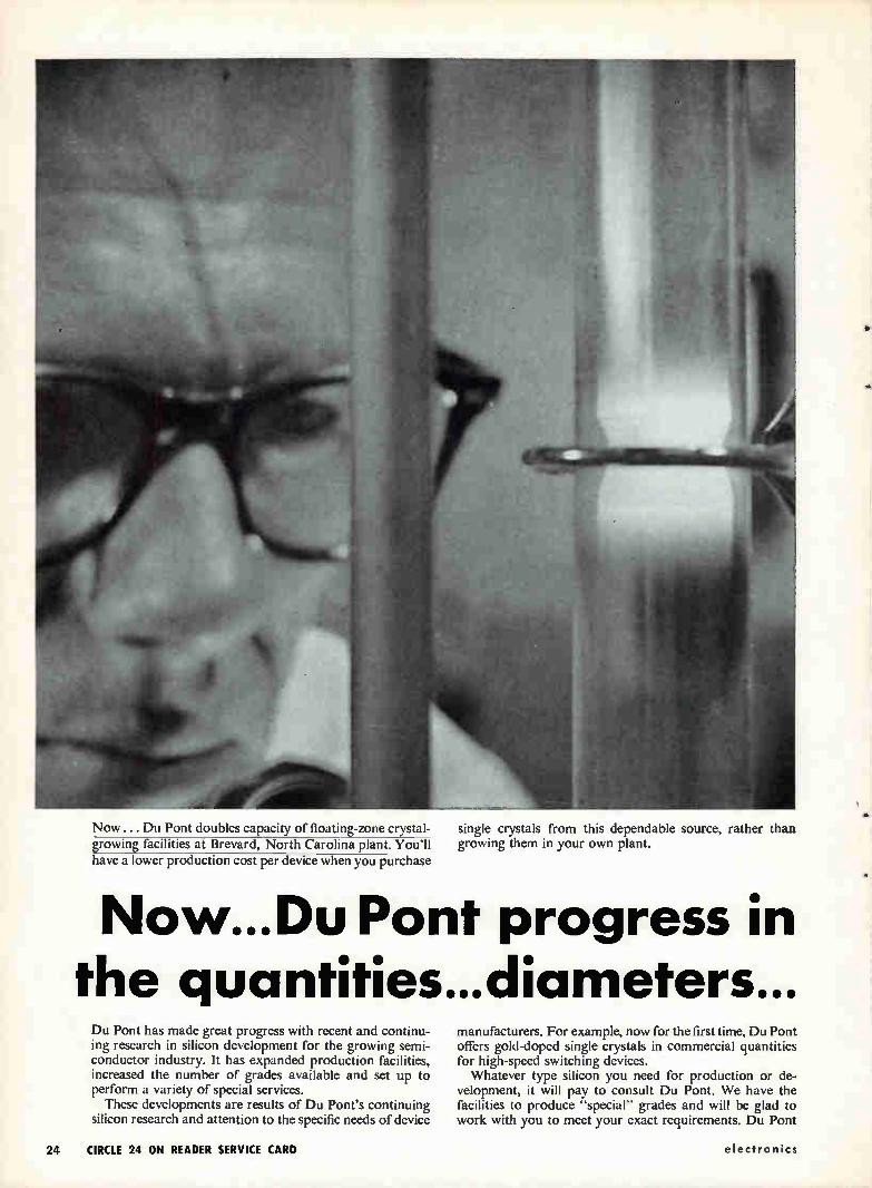
Now ... Du Pont doubles capacity of floating-zone crystal-vowing facilities ai Brevard, North Carolina plant. You'll have a lower production cost per device when you purchase
single crystals from this dependable source, rather than growing them in your own plant.
Now...Du Pont progress in the quantities...diameters... Du Pont has made great progress with recent and continu-ing research in silicon development for the growing semi-conductor industry. It has expanded production facilities, increased the number of grades available and set up to perform a variety of special services.
These developments are results of Du Pont's continuing silicon research and attention to the specific needs of device
manufacturers. For example, now for the first time, Du Pont offers gold-doped single crystals in commercial quantities for high-speed switching devices. Whatever type silicon you need for production or de-
velopment, it will pay to consult Du Pont. We have the facilities to produce "special" grades and will be glad to work with you to meet your exact requirements. Du Pont
"du
24 CIRCLE 24 ON READER SERVICE CARD electronics
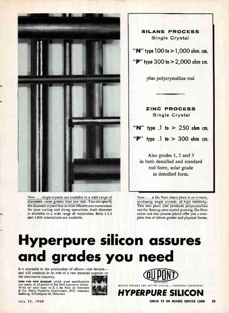
Now . . . single crystals are available in a wide range of diameters—even greater than one inch. You can specify the diameter crystal that is most efficient and economical for your cutting and dicing operations. Each diameter is available in a wide range of resistivities. Both 1:1:1 and 1:0:0 orientations are available.
SILANE PROCESS
Single Crystal
"N" type 100 to >1,000 ohm. cm.
"P" type 300 to >2,000 ohm cm.
plus polycrystalline rod
ZINC PROCESS
Single Crystal
"N" type .1 to > 250 ohm cm.
"P" type .1 to > 300 ohm cm.
Also grades 1, 2 and 3 in both densified and standard
rod form; solar grade in densified form.
Now .. . a Du Pont silane plant is on stream, producing single crystals of high resistivity. This new plant also produces polycrystalline rod for floating-zone crystal growing. Du Pont silane and zinc process plants offer you a com-plete line of silicon grades and physical forms.
Hyperpure silicon assures and grades you need is a specialist in the production of silicon—not devices— and will continue in its role of a raw material supplier to the electronics industry.
SEND FOR NEW BOOKLET which gives specifications and prices of all grades of Du Pont hyperpure silicon. Write for your copy to E. I. du Pont de Nemours & Co. (Inc.), Pigments Department, 2533 Nemours Building, Wilmington 98, Delaware.
RICu. $. PAT. OFF
BETTER THINGS FOR BETTER LIVING...THROUGH CHEMISTRY
HYPERPURE SILICON July 22, 1960 CIRCLE 25 ON READER SERVICE CARD 25
• ELIMINATE DELAYS!
• KEEP YOUR OPERATING COSTS WHERE
THEY SHOULD BEI
PORTABLE 40-POUND BENCH MODEL 106 Here .s a speedy, economical 2 or 3-dimensional engraver used
by thousands of dollar-conscious companies. It features 5 positive, accurate pantographic ratios, ball bearing spindle with 3 speeds up to 14,000
rpm. Is supplied with one copy carrier that accepts all standard master type sizes. Will actually work up to 10" by any width. Height of pantograph and position of cutter are continuously adiustable
You Make Your OW Engraved
Nameplates'
Pantograph for milling, drilling and engraving.
Vertical adjustment of cor.
table automatic with PanL. graph. Features unobstructe,
on 3 sides to take large wonii micrometer adjustment fcr depth of cut; ball bearing
construction throughout; spin-dle speeds up to 26,000 tic,
for engraving or machining vertical range over 10"; ratio, 2 to I to infinity — master
copy area 26" x 10"
NEW
MODEL D2-201 PNEUMATIC ATTACHMENT
for use with Model 02 Pantograph Engraver to rapidly drill holes in printed circuits by trac-ing templates. Drills as many as 100 holes per minute. Equipped with foot switch, spindle air cylinder; regulating valve and pressure gauge; filter and oiler. It's ready to use as soon as it's attached to an air compressor
\
GREEN INSTRUMENT COMPANY, INC.
Dept. 363, 295 Vassar St., Cambridge 39, Mass. Tel. ELiot 4-2989
MARKET RESEARCH
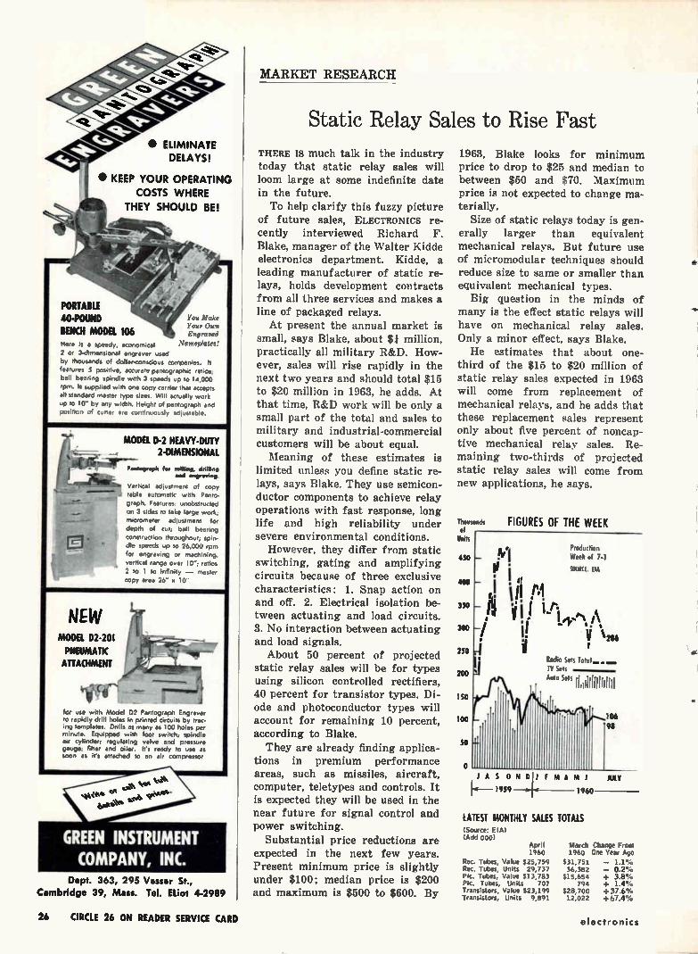
Static Relay Sales to Rise Fast THERE IS much talk in the industry today that static relay sales will loom large at some indefinite date in the future. To help clarify this fuzzy picture
of future sales, ELECTRONICS re-cently interviewed Richard F. Blake, manager of the Walter Kidde electronics department. Kidde, a leading manufacturer of static re-lays, holds development contracts from all three services and makes a line of packaged relays. At present the annual market is
small, says Blake, about $1 million, practically all military R&D. How-ever, sales will rise rapidly in the next two years and should total $15 to $20 million in 1963, he adds. At that time, R&D work will be only a small part of the total and sales to military and industrial-commercial customers will be about equal. Meaning of these estimates is
limited unless you define static re-lays, says Blake. They use semicon-ductor components to achieve relay operations with fast response, long life and high reliability under severe environmental conditions.
However, they differ from static switching, gating and amplifying circuits because of three exclusive characteristics: 1. Snap action on and off. 2. Electrical isolation be-tween actuating and load circuits. 3. No interaction between actuating and load signals.
About 50 percent of projected static relay sales will be for types using silicon controlled rectifiers, 40 percent for transistor types. Di-ode and photoconductor types will account for remaining 10 percent, according to Blake. They are already finding applica-
tions in premium performance areas, such as missiles, aircraft, computer, teletypes and controls. It is expected they will be used in the near future for signal control and power switching.
Substantial price reductions are expected in the next few years. Present minimum price is slightly under $100; median price is $200 and maximum is $500 to $600. By
1963, Blake looks for minimum price to drop to $25 and median to between $50 and $70. Maximum price is not expected to change ma-terially.
Size of static relays today is gen-erally larger than equivalent mechanical relays. But future use of micromodular techniques should reduce size to same or smaller than equivalent mechanical types.
Big question in the minds of many is the effect static relays will have on mechanical relay sales. Only a minor effect, says Blake. He estimates that about one-
third of the $15 to $20 million of static relay sales expected in 1963 will come from replacement of mechanical relays, and he adds that these replacement sales represent only about five percent of noncap-tive mechanical relay sales. Re-maining two-thirds of projected static relay sales will come from new applications, he says.
Thousands of
Units
450
400
350
300
250
200
150
100
SO
Rodio Sets Total. TV Sets
FIGURES OF THE WEEK
Production
Week of 7-1
SOURCE Elk
Auto Se" ÍÍliffirilini
106
98
JASONDJ MAMJ JULY
1-4— 1959 1 1960
LATEST MONTHLY SALES TOTALS (Source: EPA) (Add 000)
April 1960
Rec. Tubes, Value 525,759 Rec, Tubes, Units 29,737 P.c. Tubes, Value $13,783 Pic. Tubes, Units 707 Transistors, Value $23,199 Transistors, Units 9,891
March Change From 1960 One Year Ago
$31,751 — 1.1% 36,382 — 0.2%
$15,654 + 3.8% 794 + 1.4%
$28,700 +37.6% 12,022 +67.4%
26 CIRCLE 26 ON READER SERVICE CARD electronics
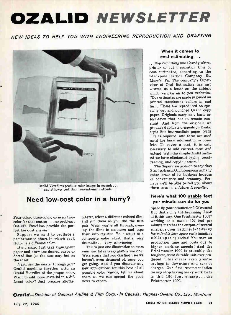
OZALID NEWSLETTER NEW IDEAS TO HELP YOU WITH ENGINEERING REPRODUCTION AND DRAFTING
Ozalid Viewfilms produce color images in seconds... and at lower cost than conventional methods.
Need low-cost color in a hurry?
Four-color, three-color, or even two-color for that matter . . . no problem; Ozalid's Viewfilms provide the per-fect low-cost answer. Suppose we want to produce a
performance chart in which each factor is a different color.
It's a snap. Just take translucent paper and draw the desired curve or dotted line (as the case may be) on the sheet.
Next, run the master through your Ozalid machine together with an Ozalid Viewfilm of the proper color. Want to add more material in a dif-ferent color? Just prepare another
master, select a different colored film, and run them as you did the first pair. When you're all through, over-lay the films in sequence and tape them into register. Your result is a composite color chart that's very dramatic . . . very convincing!
This is just one illustration to start your mental salivary glands working. We are sure that you can find uses we haven't even dreamed of, once you get going. And if you discover any new applications for this best of all possible color worlds, tell us about them so we can spread the good news to others.
When it comes to cost estimating ...
... there's nothing like a handy white-printer to cut preparation time of cost estimates, according to the Stackpole Carbon Company, St. Mary's, Pa. The company's Super-visor of Cost Estimating has just written us a letter on the subject which we pass on to you verbatim. "Our estimates are made in pencil on printed translucent vellum in pad form. These are reproduced on spe-cially cut and punched Ozalid copy paper. Originals carry only basic in-formation that has to remain con-stant. And from the originals we produce duplicate originals on Ozalid sepia line intermediate paper (#402 IT) as required, and these are used until the basic information is obso-lete. To revise a cost, it is only necessary to add current rates and extend. With this simple Ozalid meth-od we have eliminated typing, proof-reading, and copying errors." The Supervisor goes on to say that
Stack pole uses Ozalid copying in many other areas of its business because of convenience and economy. Per-haps we'll be able to tell you about these uses in a future Newsletter.
Here's what 100 usable feet per minute can do for you
Speed up your production ? Of course! But that's only the beginning. Look at it this way. One Printmaster 1000® working at a usable 100 feet per minute matches the output of several smaller, slower machines but takes up less valuable floor space while handling widths up to 54 inches! You save on production time and costs due to higher working speeds! And the Printmaster 1000 is probably the toughest, most durable unit ever pro-duced. This •means even greater savings in downtime and service charges. Our first recommendation for any shop having heavy work loads is this 100-foot champ... the Printmaster 1000.
Ozalid—Division of General Aniline & Film Corp.. In Canada: Hughes-Owens Co., Ltd., Montreal
July 22, 1960 CIRCLE 27 ON READER SERVICE CARD 27
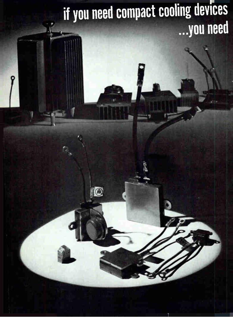
if you need compact cooling devrces ...you need

VVEST NCH SUS THERIVIOELECTR -COOLERS NOW AVAILABLE AT REDUCED PRICES Now you can have the space and weight savings of Westinghouse "Component-Matched" thermoelectric coolers—with new cost savings, too. Prices are reduced on standard units, up to 50%!
Exclusive Westinghouse "Component-Matched" configu-rations! With no moving parts, Westinghouse Thermoelectric coolers provide dependable, compact, lightweight cooling where it is necessary to reduce component temperature below ambient. These unique "Component-Matched" coolers feature exterior cool-ing surfaces or inner-cooled chambers with tailor-made dimensions to fit specific requirements. As a result of new production facilities,
a wide range of configurations can be offered to electronic equip-ment designers.
Only Westinghouse guarantees minimum AT ratings! Recent Westinghouse improvements in thermoelectric materials and assembly techniques have made it possible to guarantee mini-mum AT ratings for each cooling unit. Thus, a designer can select the unit he needs knowing in advance what the temperature drop will be from the hot to the cold side of the cooler.
Immediate military and industrial applications include: Photocells, photomultiplier tubes / Germanium transistors / In-frared detectors / Mechanical and electrical instruments / Labo-ratory and portable medical equipment / Controlling temperatures of solids, liquids and gases.
Westinghouse engineers who developed these new thermoelectric coolers will be glad to provide engineering assistance in your ap-plications. For full information, contact your local Westinghouse representative, or write: Westinghouse Electric Corporation, Semi-conductor Dept., Youngwood, Pennsylvania., sc-l000,
C O 2 4 6 I 10 12 14 18 18 20 n
Inuit current toc oler, demesne
Ty
ees
ical A T° C versus input current— Types WX814-H, WX816-H
"Buy and Try"—from Westinghouse distributors —standard WX814 and WX816 Coolers for immediate delivery at new reduced prices.
EASTERN
CAMERADIO Pittsburgh, Pa./EX 1-4000 CRAMER ELECTRONICS, INC. Boston, Mass./CO 7-4700 ELECTRONIC SUPPLY Melbourne, Florida/PA 3-1441 GENERAL RADIO SUPPLY CO., INC. Camden, N.J./WO 4-8560 KANN-ELLERT ELECTRONICS, INC. Baltimore, Md./TU 9-4242 MILGRAY ELECTRONICS New York, N.Y./RE 2-4400 RADIO & ELECTRONIC PARTS CORP.
Cleveland, Ohio/UT 1-6060 SCHWEBER ELECTRONICS Long Island, N.Y./PI 6-6520
MIDWESTERN
ELECTRONIC COMPONENTS FOR INDUSTRY CO. St. Louis, Mo./WO 2-9917
INTER-STATE RADIO &SUPPLY CO. Denver 4, Colo./TA 5-8257 LENERT CO. Houston, Texas/CA 4-2663 RADIO DISTRIBUTING CO. Indianapolis, Ind./ME 5-8311 SEMICONDUCTOR SPECIALISTS, I NC. Chicago,111./NA 2-8860 UNITED RADIO. INC. Cincinnati, Ohio/MA 1-6530
WESTERN
ELMAR ELECTRONICS Oakland, Calif./TE 4-3311 HAMILTON ELECTRO SALES Los Angeles, Calif./BR 2-8453 NEWARK ELECTRONICS CO. Inglewood, Calif./OR 4-8440
YOU CAN BE SURE—IF
Westinghouse CIRCLE 29 ON READER SERVICE CARD
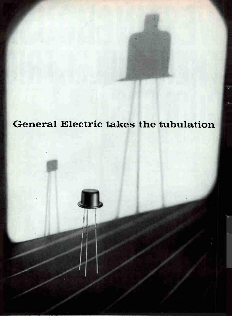
I
General Electric takes the tubulation
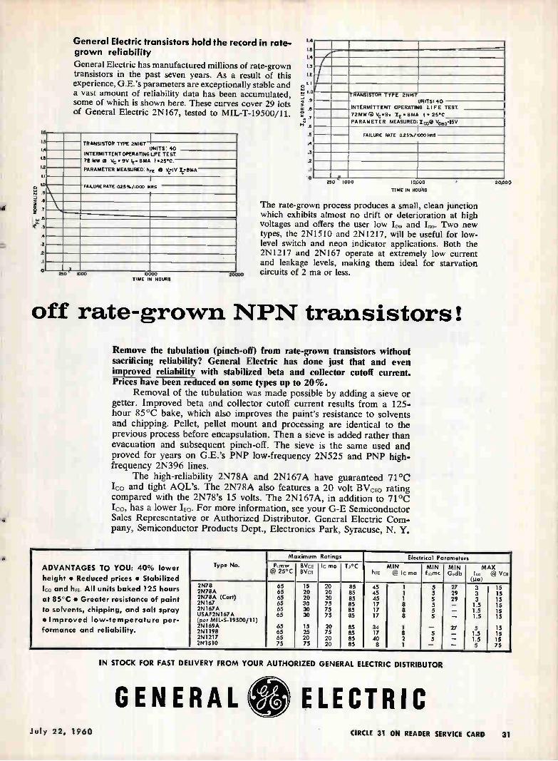
e
î
e
General Electric transistors hold the record in rate-grown reliability
General Electric has manufactured millions of rate-grown transistors in the past seven years. As a result of this experience, G.E.'s parameters are exceptionally stable and a vast amount of reliability data has been accumulated, some of which is shown here. These curves cover 29 lots of General Electric 2N167, tested to MIL-T-19500/11.
I-5"--
1.4 TRANSISTOR TYPE 2H167
INTERMITTENT OPERATING
7.2 MW 2I Vc • 9V lE• 8MA
PARAMETER MEASURED: An
UNITS: 40
L3 UFE TEST
12 t •25.c.
i.i 0 Ve IV le8MA
LO FA1WRE RATE 025%/1000 NRS
\\.„ e9
7 —. .6
5
4
3
2 .1 o 25o, 1000 MOO 9110
TIME IN HOURS
I.
1.5
1.4
1.3
1.2
LI
I. 7.1 a .9
51 .e ,
110 .5
A
.3
.2
o
-----TRANSISTOR TYPE 2NI67
INTERMITTENT OPERATING
72MW G Vc .9v IE • 8MA PARAMETER MEASURED:IcD0
UNITS 40 LI FE TEST
I • 25•C
Vc"«15V
FAILURE RATE 025%/1000 HRS
4 250 1000 10,000
TIME IN HOURS
The rate-grown process produces a small, clean junction which exhibits almost no drift or deterioration at high voltages and offers the user low II, and I. Two new types, the 2N1510 and 2N1217, will be useful for low-level switch and neon indicator applications. Both the 2N1217 and 2N167 operate at extremely low current and leakage levels, making them ideal for starvation circuits of 2 ma or less.
off rate-grown NPN transistors!
Remove the tubulation (pinch-off) from rate-grown transistors without sacrificing reliability? General Electric has done just that and even improved reliability' with stabilized beta and collector cutoff current. Prices have been reduced on some types up to 20%.
Removal of the tubulation was made possible by adding a sieve or getter. Improved beta and collector cutoff current results from a 125-hour 85°C bake, which also improves the paint's resistance to solvents and chipping. Pellet, pellet mount and processing are identical to the previous process before encapsulation. Then a sieve is added rather than evacuation and subsequent pinch-off. The sieve is the same used and proved for years on G.E.'s PNP low-frequency 2N525 and PNP high. frequency 2N396 lines.
The high-reliability 2N78A and 2N167A have guaranteed 71 °C lc° and tight AQL's. The 2N78A also features a 20 volt BVcE0 rating compared with the 2N78's 15 volts. The 2N167A, in addition to 71°C Ico, has a lower IE0. For more information, see your G-E Semiconductor Sales Representative or Authorized Distributor. General Electric Com-pany, Semiconductor Products Dept., Electronics Park, Syracuse, N. Y.
20.000
Maximum Ratings Elect ical Parameters
ADVANTAGES TO YOU: 40% lower Type No. P,mw @ 25°C
BV,,E 'Pica
I_ ma TJ°C MIN hFE @ lc ma
MIN fa.mc
MIN Gedb
MAX I o @ Vce
height • Reduced prices • Stabilized (ga) 1co hFE. All baked 125 hours
2N78 65 15 20 85 45 I 5 27 3 15 and units 2N78A 65 20 20 85 45 1 5 29 3 15 at 85°C • Greater resistance of paint 2N78A (Cert)
2N167 65 65
20 30
20 75
85 85
45 17
1 8
5 5
29 —
3
1.5
15
15 to solvents, chipping, and salt spray 2N167A 65 30 75 85 17 8 5 — 1.5 15
• Improved low-temperature per- USAF2N167A (per MIL-S-19500/11)
65 30 75 85 17 8 5 — 1.5 15
formance 2N 169A 65 15 20 85 34 1 — 27 5 15 and reliability. 2N1198 65 25 75 85 17 8 5 — 1.5 15 2N1217 65 20 20 85 40 2 5 — 1.5 15 2N1510 75 75 20 85 8 1 — — 5 75
IN STOCK FOR FAST DELIVERY FROM YOUR AUTHORIZED GENERAL ELECTRIC DISTRIBUTOR
GENERAL ELECTRIC July 22, 1960 CIRCLE 31 ON READER SERVICE CARD 31

To help conquer extremes ... from known to
32 CIRCLE 32 ON READER SERVICE CARD electronics
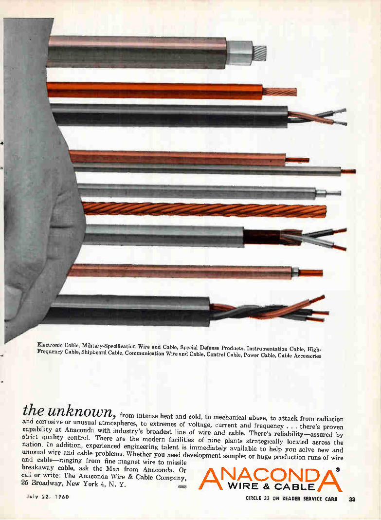
Electronic Cable, Military-Specification Wire and Cable, Special Defense Products, Instrumentation Cable, High-Frequency Cable, Shipboard Cable, Communication Wire and Cable, Control Cable, Power Cable, Cable Accessories
the unknown, from intense heat and cold, to mechanical abuse, to attack from radiation and corrosive or unusual atmospheres, to extremes of voltage, current and frequency . there's proven capability at Anaconda with industry's broadest line of wire and cable. There's reliability—assured by strict quality control. There are the modern facilities of nine plants strategically located across the nation. In addition, experienced engineering talent is immediately available to help you solve new and unusual wire and cable problems. Whether you need development samples or huge production runs of wire and cable—ranging from fine magnet wire to missile breakaway cable, ask the Man from Anaconda. Or call or write: The Anaconda Wire & Cable Company, NACON DA 25 Broadway, New York 4, N. Y. 00206 A WIRE 8( CABLE
July 22. 1960 (EMU 33 ON READER SERVICE CARD 33
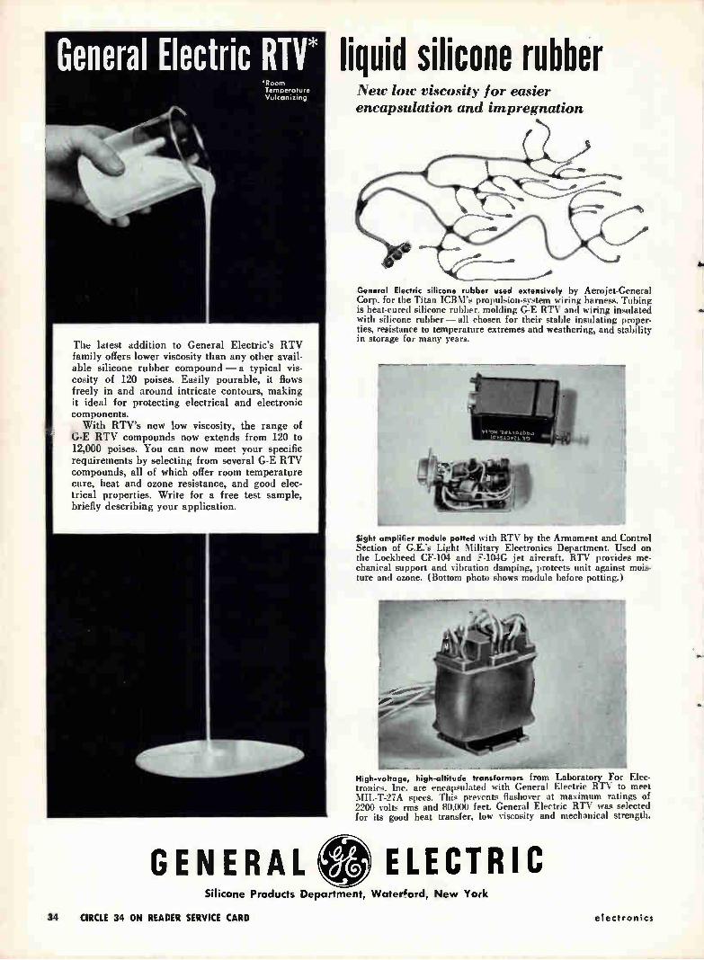
General Electric RTV* 'Room Temperature Vulcanizing
00414.40-1- \ \ *it , 1,
,
The latest addition to General Electric's RTV family offers lower viscosity than any other avail-able silicone rubber compound — a typical vis-cosity of 120 poises. Easily pourable, it flows freely in and around intricate contours, making it ideal for protecting electrical and electronic components.
With RTV's new low viscosity, the range of G-E RTV compounds now extends from 120 to 12,000 poises. You can now meet your specific requirements by selecting from several G-E RTV compounds, all of which offer room temperature cure, heat and ozone resistance, and good elec-trical properties. Write for a free test sample, briefly describing your application.
GENERAL
liquid silicone rubber New low viscosity for easier encapsulation and impregnation
General Electric silicone rubber used extensively by Aerojet-General Corp. for the Titan ICBM's propulsion-system wiring harness. Tubing is heat-cured silicone rubber, molding G-E RTV and wiring insulated with silicone rubber — all chosen for their stable insulating proper-ties, resistance to temperature extremes and weathering, and stability in storage for many years.
Sight amplifier module potted with RTV by the Armament and Control Section of G.E.'s Light Military Electronics Department. Used on the Lockheed CF-104 and F-104G jet aircraft, RTV provides me-chanical support and vibration damping, protects unit against mois-ture and ozone. (Bottom photo shows module before potting.)
Nigh-voltage, high-altitude transformers from Laboratory For Elec-tronics. Inc. are encapsulated with General Electric RTV to meet MIL-T-27A specs. This prevents flashover at maximum ratings of 2200 volts rms and 80,000 feet. General Electric RTV was selected for its good heat transfer, low viscosity and mechanical strength.
ELECTRIC Silicone Products Department, Water‘ord, New York
34 CIRCLE 34 ON READER SERVICE CARD electronics

CIRCLE 250 ON READER SERVICE C
sophisticated WEAPON SYSTEMS have
This unique WEAPON SYSTEM and other
PP
pp
— . rp.,
▪
.-. î
CD
M M C ^ •
z
M
.>
---.
.-,-
a.
,.,,
Ir
q
1 o
.,.-‘
CD
J'
z
•
"C5
M"
— z o 0 0
CD
1cl
o à
Pi)
e-t-
i•
e (D Z 0 e
e.
‹ -
el) Z g
eP
5
2".
ICJ;
8
z
C2
31:1
e.
,-,
-•
.....
-u,
a.
e3.
cr9c
. 0
<1:'
1-s
gl.
o
11.3.
.., o
e e g
•o m
rt- 0 z e•
o z =
ct, ii 7 eD
PROFESSIONAL EMPLOYMENT INQUIRY
This card may be folded and sealed or stapled and mailed in
complete co
nfid
ence
. It
wi
ll enable
the pr
ofes
sion
al st
aff
at Convair-Pomona to make a preliminary evaluation of your background.
A personal interview can be arranged in
your ci
ty by appointment. U. S. Citizenship required.
Every completed inquiry w
ill be acknowledged.
PERSONAL INFORMATION (PLEASE PRINT)
NAME
STREET ADDRESS
CITY a STATF
'TELEPHONE
EDUCATION
DS
MS PhD Date (s)
es
ilas
PhD Date (s)
EE
0
0
CI
Physics
CI
O
0
ME
D
CI
CI
Other
CI
CI
CI
Mathematics 0
CI
CI
0
0
0
o
.r o
Plea
se i
ndicate yo
ur qua
lifi
cati
ons
below.
ELECTRONICS:
LI WEAPONS SYSTEMS
C SYSTEMS ANALYSIS
C GUIDANCE AND CONTROL
SYSTEMS
ID COMPONENT EVALUATION
CI TEST EQUIPMENT
DEVELOPMENT
D MICROWAVE AND
ANTENNA DEVELOPMENT
FLIGHT ANALYSIS
D INSTRUMENTATION
C RADAR SYSTEMS
C PUBLICATIONS
ENGINEERING
D SYSTEMS TEST
D SUB-CONTRACT
COORDINATION
C MICRO & MOLECTRONICS
D SOLID STATE CIRCUIT
DESIGN
D INFRARED SYSTEMS
PHYSICS:
D PHYSICAL ELECTRONICS
D SOLID STATE PHYSICS
D MAGNETICS
OPTICS
D INFRARED SYSTEMS
C THEORETICAL PHYSICS
AERONAUTICS:
C AERODYNAMICS
D ST
RUCTURAL DYNAMICS
C AEROELASTICITY
D AEROTHERMODYNAMICS
MECHANICS:
ID APPLIED MECHANICS
D THERMODYNAMICS
APPLIED MATH:
C NUMERICAL ANALYSIS
& STATISTICS
PSYCHOLOGY:
HUMAN FACTORS
OPERATIONS RESEARCH:
COMMUNICATION & AIR
TRAFFIC CONTROL
SYNTHESIS & EVALUATION
D BIONICS
OTHER
School (Highest Degree)
PLEASE SEND CONVAIFt/POMONA ENGINEERING DEPARTMENT BROCHURE
MAULER ...a NEW highly mobile battlefield air defense missile system for the United States Army
CONVAIR/POMONA as WEAPON SYS-
TEM MANAGER on the MAULER
program has again proven the creative capa-
bilities of their Engineers and Scientists.
MAULER is a completely new weapon
system which is capable of destroying short-
range ballistic missiles, rockets, and high-
performance low-flying tactical aircraft.
Because of MAULER being a completely
CONVAIR/POMONA
new weapon-system and the other advance
programs in the phases of research, develop-
ment, and production design, there is now a
need for competent Engineers and Scientists
who would like to join this team of creative
engineers.
If you feel that you might be able to con-
tribute to the MAULER and other advanced
programs, CONVAIR/POMONA would like
the opportunity to explore your capabilities.
cDowNISvIAOINR GENERAL DYNAMICS OF
CIRCLE 251 ON READER SERVICE CARD FOR MORE INFORMATION
REDEYE ... a NEW shoulder-fired antiaircraft weapon being developed for the U. S. Army and Marines
The NEW shoulder-launched guided missile
is being developed at CONVAIR/POMONA.
REDEYE the one-man weapon will give our
ground troops an effective fighting chance
against, low-strafing and bombing aircraft.
This unique WEAPON SYSTEM and other
sophisticated WEAPON SYSTEMS have
created an immediate need for Engineers and
Scientists with proven capabilities in re-
CONVAIRPOIVIONA
search, development and production design.
The Pomona Valley is one of the finest
recreational, educational and cultural centers
to be found. This verdant area is the home of
CONVAIR/POMONA.
If you are interested in contributing to CON-
VAIR/POMONA'S WEAPON SYSTEM
concept, you are invited to complete the at-
tached inquiry.
CONVAIR
DIVOISFION GENERAL DYNAMICS
CIRCLE 250 ON READER SERVICE CARD FOR MORE INFORMATION
MAULER ...a NEW highly mobile battlefield air defense missile system for the United States Army
CONVAIR/POMONA as WEAPON SYS-
TEM MANAGER on the MAULER
program has again proven the creative capa-
bilities of their Engineers and Scientists.
MAULER is a completely new weapon
system which is capable of destroying short-
range ballistic missiles, rockets, and high-
performance low-flying tactical aircraft.
Because of MAULER being a completely
CONVAIR/POMONA
new weapon-system and the other advance
programs in the phases of research, develop-
ment, and production design, there is now a
need for competent Engineers and Scientists
who would like to join this team of creative
engineers.
If you feel that you might be able to con-
tribute to the MAULER and other advanced
programs, CONVAIR/POMONA would like
the opportunity to explore your capabilities.
CONVAIR DIVISION GENERAL DYNAMICS OF
CIRCLE 251 ON READER SERVICE CARD FOR MORE INFORMATION
Tit littritotiett
looking
Into In,,
60's
9as
RESERRCH .• DEVELOPMEITT
R-8
R-5
R-7
Eirltaucta et Titinstorrn Techniqtee
R-9
Editorial Reprints Still Available... If You Act Now...
Following are editorial reprints available from stock. However, reprints of any editorial that has appeared in electronics in past or current issues may be or-dered. For reprints not listed below prices will vary depending upon the length of the article.
Instruments for Design and Production, December 4, 1959; Key No. R-2: a 16-page report on Voltage, Current and Power Measurement; Impedance Measurement; Frequency
Measurement; Waveform Measurement; Tube and Semiconductor Testing; Automatic Testing. Profusely illustrated with charts and graphs.
1959 Index to electronics, December 25, 1959; Key No. R-4: a handy 32-page index to the
3,000-plus pages of technical and technically interpreted business information that ap-peared in electronics during 1959.
The Electronics Market: "Looking into the 60's", January 1, 1960; Key No. R-5: is the
result of one year's intensive research effort to reveal the U. S. Market, the Manpower Picture, Precise breakdown of the Military, Industrial, Consumer and Replacement Parts
Markets with charts, graphs, tables, Buying and Selling Abroad and new approaches in Getting Goods to Market.
Designing High-Power Transistor Oscillators, January 8, 1960; Key No. R-6. 50c each: reprint of a 4-page article by W. E. Roach, Pacific Semiconductors, Inc. New high-power
transistors are usable at over 300mc. Oscillator design is simplified with step-by-step procedure.
Research & Development Around The World, February 12, 1960; Key No. R-7: a 24-page roundup in the countries covered within this report by men recognized as expert ... men
who were approached personally in electronics' behalf by McGraw-Hill's unique World
News Bureau, and we are particularly indebted to representatives in London, Paris, Milan, Stockholm, Zurich, Tel Aviv, Tokyo and Melbourne for the result.
Graphical Extension of Transform Techniques, April 1, 1960; Key No. R-8. 50c each: a 6-page reprint of a feature article that deals with those engineering problems solved
more readily with functional — transformation methods. The article reviews Fourier and convolution integrals and presents a graphical convolution technique.
What's New in Electron Tubes, April 29, 1960; Key No. R-9. 50c each: 36-page illustrated report of the latest advances and developments in a classic field of electronics. Thorough
analysis of Receiving-Type Tubes, High Vacuum Power Tubes, Gas Filled Tubes, Linear-Beam Microwave Tubes, Crossed-Field Microwave Tubes, Cathode-Ray Tubes, Storage, Counting and Phototubes.
Prices: Reprints on items above are 1-10 copies, 75c each; 11-24 copies, 60c each; 25 copies or more 50c each unless otherwise noted.
r— Fill in, clip out and mail to:
electronics Reprint Service Dept., 330 W. 42nd Street, New York 36, N. Y.
electronics REPRINT ORDER FORM For Reprints of all Key Numbers listed above fill in below:
Send me Reprints of Key No(s), at c ea.
For Reprints of other editorial articles in this issue, fill in below:
Send me reprints of article entitled
on page(s) (Minimum order 100 copies)
For Reprints of other editorial articles in past issues, fill in be!ow:
Send me reprints of article entitled
on page(s) of issue dated . (Minimum order 100 copies)
Check one box *First advise me of costs Mail immediately and bill me later. L
Name
Number and Street _
City, Zone No., State
L____ _----------------
July 22, 1960
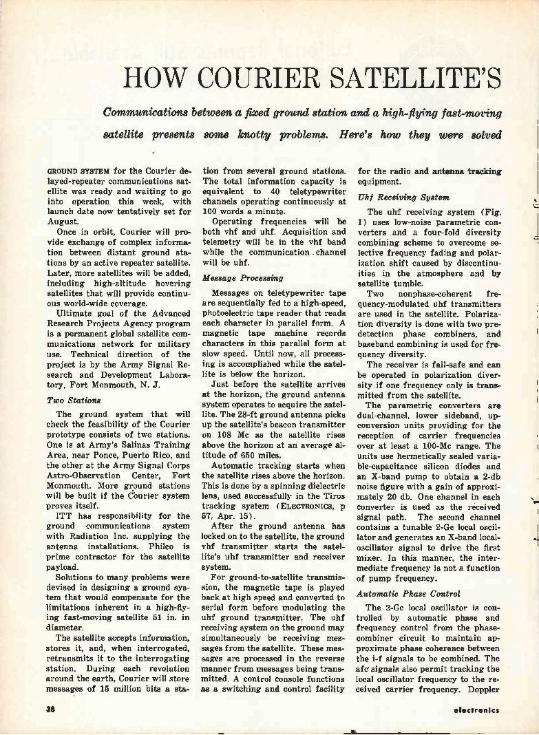
HOW COURIER SATELLITE'S Communications between a fixed ground station and a high-flying fast-moving
satellite presents some knotty problems. Here's how they were solved
GROUND SYSTEM for the Courier de-layed-repeater communications sat-ellite was ready and waiting to go into operation this week, with launch date now tentatively set for August. Once in orbit, Courier will pro-
vide exchange of complex informa-tion between distant ground sta-tions by an active repeater satellite. Later, more satellites will be added, including high-altitude hovering satellites that will provide continu-ous world-wide coverage.
Ultimate goal of the Advanced Research Projects Agency program is a permanent global satellite com-munications network for military use. Technical direction of the project is by the Army Signal Re-search and Development Labora-tory, Fort Monmouth, N. J.
Two Stations
The ground system that will check the feasibility of the Courier prototype consists of two stations. One is at Army's Salinas Training Area, near Ponce, Puerto Rico, and the other at the Army Signal Corps Astro-Observation Center, Fort Monmouth. More ground stations will be built if the Courier system proves itself. ITT has responsibility for the
ground communications system with Radiation Inc. supplying the antenna installations. Philco is prime contractor for the satellite payload.
Solutions to many problems were devised in designing a ground sys-tem that would compensate for the limitations inherent in a high-fly-ing fast-moving satellite 51 in. in diameter. The satellite accepts information,
stores it, and, when interrogated, retransmits it to the interrogating station. During each revolution around the earth, Courier will store messages of 15 million bits a sta-
tion from several ground stations. The total information capacity is equivalent to 40 teletypewriter channels operating continuously at 100 words a minute.
Operating frequencies will be both vhf and uhf. Acquisition and telemetry will be in the vhf band while the communication channel will be uhf.
Message Processing
Messages on teletypewriter tape are sequentially fed to a high-speed, photoelectric tape reader that reads each character in parallel form. A magnetic tape machine records characters in this parallel form at slow speed. Until now, all process-ing is accomplished while the satel-lite is below the horizon.
Just before the satellite arrives at the horizon, the ground antenna system operates to acquire the satel-lite. The 28-ft ground antenna picks up the satellite's beacon transmitter on 108 Mc as the satellite rises above the horizon at an average al-titude of 650 miles.
Automatic tracking starts when the satellite rises above the horizon. This is done by a spinning dielectric lens, used successfully in the Tiros tracking system (ELECTRONICS, p 57, Apr. 15).
After the ground antenna has locked on to the satellite, the ground vhf transmitter starts the satel-lite's uhf transmitter and receiver system. For ground-to-satellite transmis-
sion, the magnetic tape is played back at high speed and converted to serial form before modulating the uhf ground transmitter. The uhf receiving system on the ground may simultaneously be receiving mes-sages from the satellite. These mes-sages are processed in the reverse manner from messages being trans-mitted. A control console functions as a switching and control facility
for the radio and antenna tracking equipment.
Uhf Receiving System
The uhf receiving system (Fig. 1) uses low-noise parametric con-verters and a four-fold diversity combining scheme to overcome se-lective frequency fading and polar-ization shift caused by discontinu-ities in the atmosphere and by satellite tumble. Two nonphase-coherent fre-
quency-modulated uhf transmitters are used in the satellite. Polariza-tion diversity is done with two pre-detection phase combiners, and baseband combining is used for fre-quency diversity. The receiver is fail-safe and can
be operated in polarization diver-sity if one frequency only is trans-mitted from the satellite. The parametric converters are
dual-channel, lower sideband, up-conversion units providing for the reception of carrier frequencies over at least a 100-Mc range. The units use hermetically sealed varia-ble-capacitance silicon diodes and an X-band pump to obtain a 2-db noise figure with a gain of approxi-mately 20 db. One channel in each converter is used as the received signal path. The second channel contains a tunable 2-Gc local oscil-lator and generates an X-band local-oscillator signal to drive the first mixer. In this manner, the inter-mediate frequency is not a function of pump frequency.
Automatic Phase Control
The 2-Oc local oscillator is con-trolled by automatic phase and frequency control from the phase-combiner circuit to maintain ap-proximate phase coherence between the i-f signals to be combined. The aft signals also permit tracking the local oscillator frequency to the re-ceived carrier frequency. Doppler
38 electronics
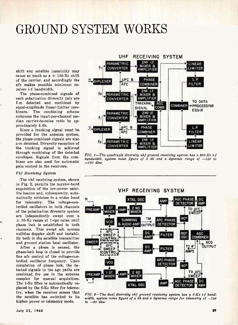
GROUND SY
shift and satellite instability may cause as much as a ± 150-Kc shift of the carrier, and accordingly the afc makes possible minimum re-
- ceiver i-f bandwidth. The phase-combined signals of
each polarization diversity pair are f-m detected and combined by equal-amplitude linear-limiter com-biners. The combining scheme enhances the input-per-channel me-dian carrier-to-noise ratio by ap-proximately 4 db.
Since a tracking signal must be provided for the antenna system, the phase-combined signals are also a-m detected. Diversity reception of the tracking signal is achieved through combining of the detected envelopes. Signals from the com-biner are also used for automatic gain control in the receivers.
,•
Vhf Receiving System
The vhf receiving system, shown in Fig. 2, permits the narrow-band acquisition of the low-power satel-lite beacon and, subsequently, auto-matically switches to a wider band for telemetry. The voltage-con-trolled oscillators in both channels of the polarization diversity system are independently swept over a -±- 10-Kc range at 1-cps rates until phase lock is established in both channels. This swept afc system nullifies doppler shift and instabil-ity both in the satellite transmitter and ground station local oscillator.
After a phase is sensed, the phase-lock loop is closed to provide fine afc control of the voltage-con-trolled oscillator frequency. Upon completion of phase lock, the de-tected signals in the age paths are combined for use in the antenna complex for manual acquisition. The 1-Ke filter is automatically re-placed by the 6-Kc filter for teleme-try, when the receiver senses that the satellite has switched to its higher power or telemetry mode.
STEM WORKS
UHF RECEIVING SYSTEM
PARAMETRIC
CONVERTER
DIPLEXER PC
AFC
PARAMETRIC
CONVERTER
PARAMETRIC
CONVERTER
APC &
AFC
PARAMETRIC CONVERTER
2ND If MIXER & AMPLI FIER
PHASE
COMBINER
2ND I F MIXER &
AMPLIFIER
TRACKING
SIGNAL
2ND If MIXER & AMPLIFIER
2ND I F • MIXER & AMPLIFIER
FIG. 1— The quadruple diversity bandwidth, system noise figure of 3 db and a dynamic range of —140 —100 dbw
COMBINER
LI NEAR LIMITER
TO DATA PROCESSING
EQUIP
L. P
FILTER
LI NEAR LIM ITER
uhf ground receiving system has a 200-Ke i-f to
I ST PREAMP MIXER
SWEEP
r AFC ; SWEEP LCONT ROL;
r---1 AFC SWEEP
'CONTROL)
VHF RECEIVING SYSTEM
XTAL OSC
2 ND MIXER
SUMMING a AUDIO AMP
TM
OUTPUT
ige VCO
I ST AMP MIXER
AGC PHASE DETECTOR
APC PHASE DETECTOR
2 ND MIXER
XTAL OSC AMP
DC AMP
TO eFC SWEEP
AGC COMBINER
T2 IF
AMPS
Le ACQ OUTPUT
TO AFC SWEEP
• -
FIG. 2—The dual diversity vhf ground receiving system has a 6-Kc band-width, system noise figure of 4 db and a dynamic range for telemetry of —145 to —90 dbw
July 22, 1960 39
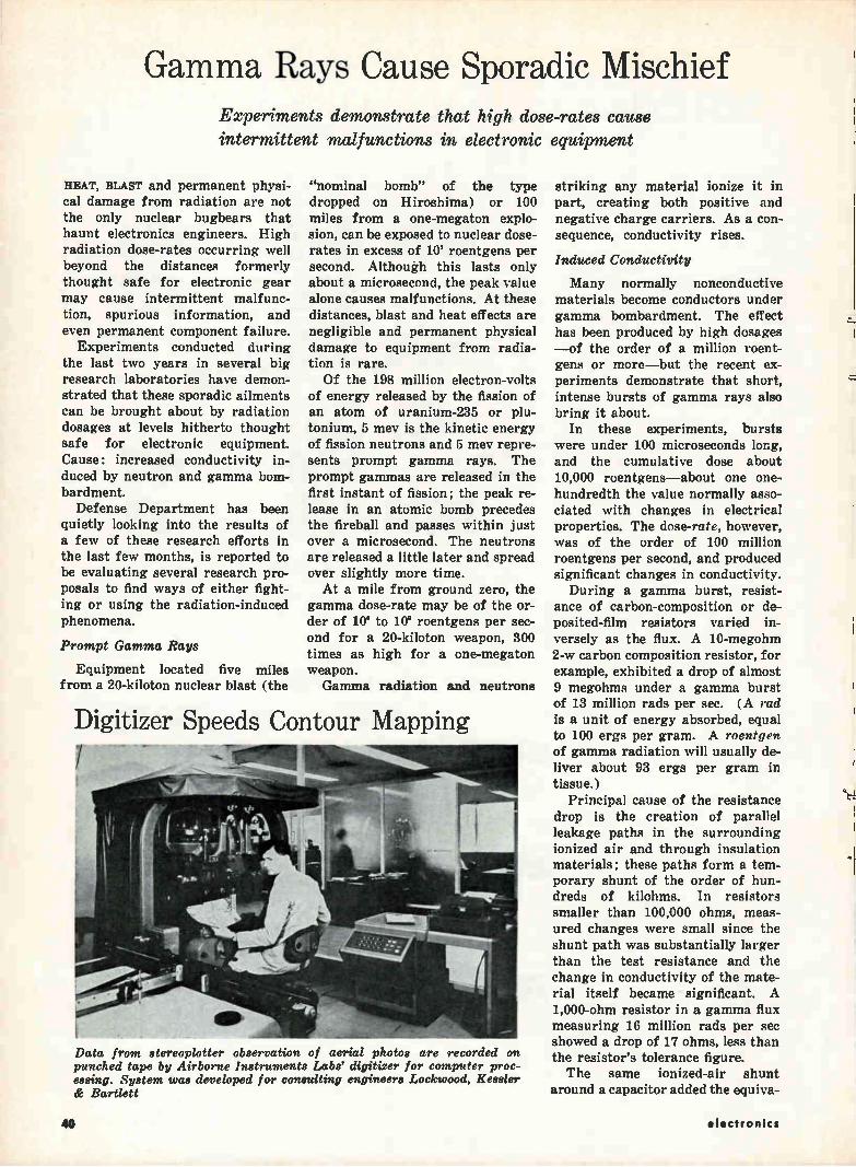
Gamma Rays Cause Sporadic Mischief Experiments demonstrate that high dose-rates cause intermittent malfunctions in electronic equipment
HEAT, BLAST and permanent physi-cal damage from radiation are not the only nuclear bugbears that haunt electronics engineers. High radiation dose-rates occurring well beyond the distances formerly thought safe for electronic gear may cause intermittent malfunc-tion, spurious information, and even permanent component failure.
Experiments conducted during the last two years in several big research laboratories have demon-strated that these sporadic ailments can be brought about by radiation dosages at levels hitherto thought safe for electronic equipment. Cause: increased conductivity in-duced by neutron and gamma bom-bardment. Defense Department has been
quietly looking into the results of a few of these research efforts in the last few months, is reported to be evaluating several research pro-posals to find ways of either fight-ing or using the radiation-induced phenomena.
Prompt Gamma Rays
Equipment located five miles from a 20-kiloton nuclear blast (the
"nominal bomb" of the type dropped on Hiroshima) or 100 miles from a one-megaton explo-sion, can be exposed to nuclear dose-rates in excess of 10' roentgens per second. Although this lasts only about a microsecond, the peak value alone causes malfunctions. At these distances, blast and heat effects are negligible and permanent physical damage to equipment from radia-tion is rare. Of the 198 million electron-volts
of energy released by the fission of an atom of uranium-235 or plu-tonium, 5 mev is the kinetic energy of fission neutrons and 5 mev repre-sents prompt gamma rays. The prompt gammas are released in the first instant of fission; the peak re-lease in an atomic bomb precedes the fireball and passes within just over a microsecond. The neutrons are released a little later and spread over slightly more time. At a mile from ground zero, the
gamma dose-rate may be of the or-der of 108 to 108 roentgens per sec-ond for a 20-kiloton weapon, 300 times as high for a one-megaton weapon. Gamma radiation and neutrons
Digitizer Speeds Contour Mapping
Data from stereo plotter observation of aerial photos are recorded on punched tape by Airborne Instruments Labs' digitizer for computer proc-essing. System was developed for consulting engineers Lockwood, Kessler & Bartlett
striking any material ionize it in part, creating both positive and negative charge carriers. As a con-sequence, conductivity rises.
Induced Conductivity
Many normally nonconductive materials become conductors under gamma bombardment. The effect has been produced by high dosages —of the order of a million roent-gens or more—but the recent ex-periments demonstrate that short, intense bursts of gamma rays also bring it about.
In these experiments, bursts were under 100 microseconds long, and the cumulative dose about 10,000 roentgens—about one one-hundredth the value normally asso-ciated with changes in electrical properties. The dose-rate, however, was of the order of 100 million roentgens per second, and produced significant changes in conductivity. During a gamma burst, resist-
ance of carbon-composition or de-posited-film resistors varied in-versely as the flux. A 10-megohm 2-w carbon composition resistor, for example, exhibited a drop of almost 9 megohms under a gamma burst of 13 million rads per sec. (A rad is a unit of energy absorbed, equal to 100 ergs per gram. A roentgen of gamma radiation will usually de-liver about 93 ergs per gram in tissue.)
Principal cause of the resistance drop is the creation of parallel leakage paths in the surrounding ionized air and through insulation materials; these paths form a tem-porary shunt of the order of hun-dreds of kilohms. In resistors smaller than 100,000 ohms, meas-ured changes were small since the shunt path was substantially larger than the test resistance and the change in conductivity of the mate-rial itself became significant. A 1,000-ohm resistor in a gamma flux measuring 16 million rads per sec showed a drop of 17 ohms, less than the resistor's tolerance figure. The same ionized-air shunt
around a capacitor added the equiva-
44 electronics
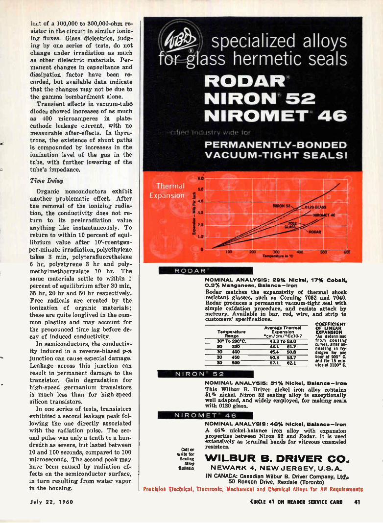
lelt of a 100,000 to 300,000-ohm re-sistor in the circuit in similar ioniz-ing fluxes. Glass dielectrics, judg-ing by one series of tests, do not change under irradiation as much as other dielectric materials. Per-manent changes in capacitance and dissipation factor have been re-corded, but available data indicate that the changes may not be due to the gamma bombardment alone.
Transient effects in vacuum-tube diodes showed increases of as much as 400 microamperes in plate-cathode leakage current, with no measurable after-effects. In thyra-trons, the existence of shunt paths is compounded by increases in the ionization level of the gas in the tube, with further lowering of the tube's impedance.
Time Delay
Organic nonconductors exhibit another problematic effect. After the removal of the ionizing radia-tion, the conductivity does not re-turn to its preirradiation value anything like instantaneously. To return to within 10 percent of equi-librium value after 107-roentgen-per-minute irradiation, polyethylene takes 3 min, polyterafluorethelene 6 hr, polystyrene 3 hr and poly-methylmethacryalate 10 hr. The same materials settle to within 1 percent of equilibrium after 30 min, 35 hr, 20 hr and 50 hr respectively. Free radicals are created by the ionization of organic materials; these are quite longlived in the com-mon plastics and may account for the pronounced time lag before de-cay of induced conductivity.
In semiconductors, the conductiv-ity induced in a reverse-biased p-n junction can cause especial damage. Leakage across this junction can result in permanent damage to the transistor. Gain degradation for high-speed germanium transistors is much less than for high-speed silicon transistors.
In one series of tests, transistors exhibited a second leakage peak fol-lowing the one directly associated with the radiation pulse. The sec-ond pulse was only a tenth to a hun-dredth as severe, but lasted between 10 and 100 seconds, compared to 100 microseconds. The second peak may have been caused by radiation ef-fects on the semiconductor surface, in turn resulting from water vapor in the housing.
RODAR"
specialized alloys (-r- ass hermetic seals
RODAR NIRON 52 NIROMET 46
}Oust I v vVicie fiOf
PERMANENTLY-BONDED VACUUM-TIGHT SEALS!
NOMINAL ANALYSIS: 29% Nickel, 17% Cobalt, 0.3% Manganese, Balance—iron
Rodar matches the expansivity of thermal shock resistant glasses, such as Corning 7052 and 7040. Rodar produces a permanent vacuum-tight seal with simple oxidation procedure, and resists attack by mercury. Available in bar, rod, wire, and strip to customers' specifications.
Temperature Range
30* To 200°C. 43.3 To 53.0 30 300 44.1 51.7 30 400 30 450 50.3 53.7 30 500
Average Thermal Expansion
•cm/cm/°Cx10-7
45.4 50.8
57.1 62.1
NIRON 52
COEFFICIENT OF LINEAR EXPANSION *As determined from cooling curves, after an-nealing In hy-drogen for one hour at 900° C. and for 15 min-utes at 1100° C.
NOMINAL ANALYSIS: 51% Nickel, Balance—Iron
This Wilbur B. Driver nickel iron alloy contains 51% nickel. Niron 52 sealing alloy is exceptionally well adapted, and widely employed, for making seals with 0120 glass.
NIROMET 46
Call or write for Sealing
Alloy Sulletin
NOMINAL ANALYSIS: 46% Nickel, Balance—Iron
A 46% nickel-balance iron alloy with expansion properties between Niron 52 and Rodar. It is used extensively as terminal bands for vitreous enameled resistors.
WILBUR B. DRIVER CO. NEWARK 4, NEW JERSEY, U.S.A.
IN CANADA: Canadian Wilbur B. Driver Company, Ltd. 50 Ronson Drive, Rexdale (Toronto)
Precision Electrical, Electronic, Itechamcal and Chemical Alloys for All Requirements
July 22, 1960 CIRCLE 41 ON READER SERVICE CARD 41
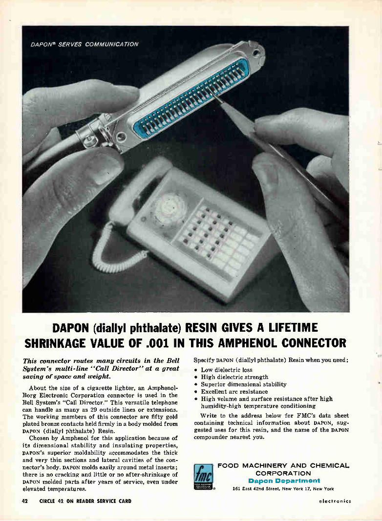
DAPON (diallyl phthalate) RESIN GIVES A LIFETIME SHRINKAGE VALUE OF .001 IN THIS AMPHENOL CONNECTOR This connector routes many circuits in the Bell System's multi-line "Call Director" at a great
saving of space and weight.
About the size of a cigarette lighter, an Amphenol-Borg Electronic Corporation connector is used in the Bell System's "Call Director." This versatile telephone can handle as many as 29 outside lines or extensions. The working members of this connector are fifty gold plated bronze contacts held firmly in a body molded from DAPON (diallyl phthalate) Resin.
Chosen by Amphenol for this application because of its dimensional stability and insulating properties, DAPON'S superior moldability accommodates the thick and very thin sections and lateral cavities of the con-nector's body. DAPON molds easily around metal inserts; there is no cracking and little or no after-shrinkage of DAPON molded parts after years of service, even under elevated temperatures.
Specify DAPON (diallyl phthalate) Resin when you need:
• Low dielectric loss • High dielectric strength • Superior dimensional stability • Excellent arc resistance • High volume and surface resistance after high
humidity-high temperature conditioning
Write to the address below for FMC's data sheet containing technical information about DAPON, sug-gested uses for this resin, and the name of the DAPON compounder nearest you.
000
FOOD MACHINERY AND CHEMICAL CORPORATION
Dapon Department
161 East 42nd Street, New York 17, New York
42 CIRCLE 42 ON READER SERVICE CARD electronics
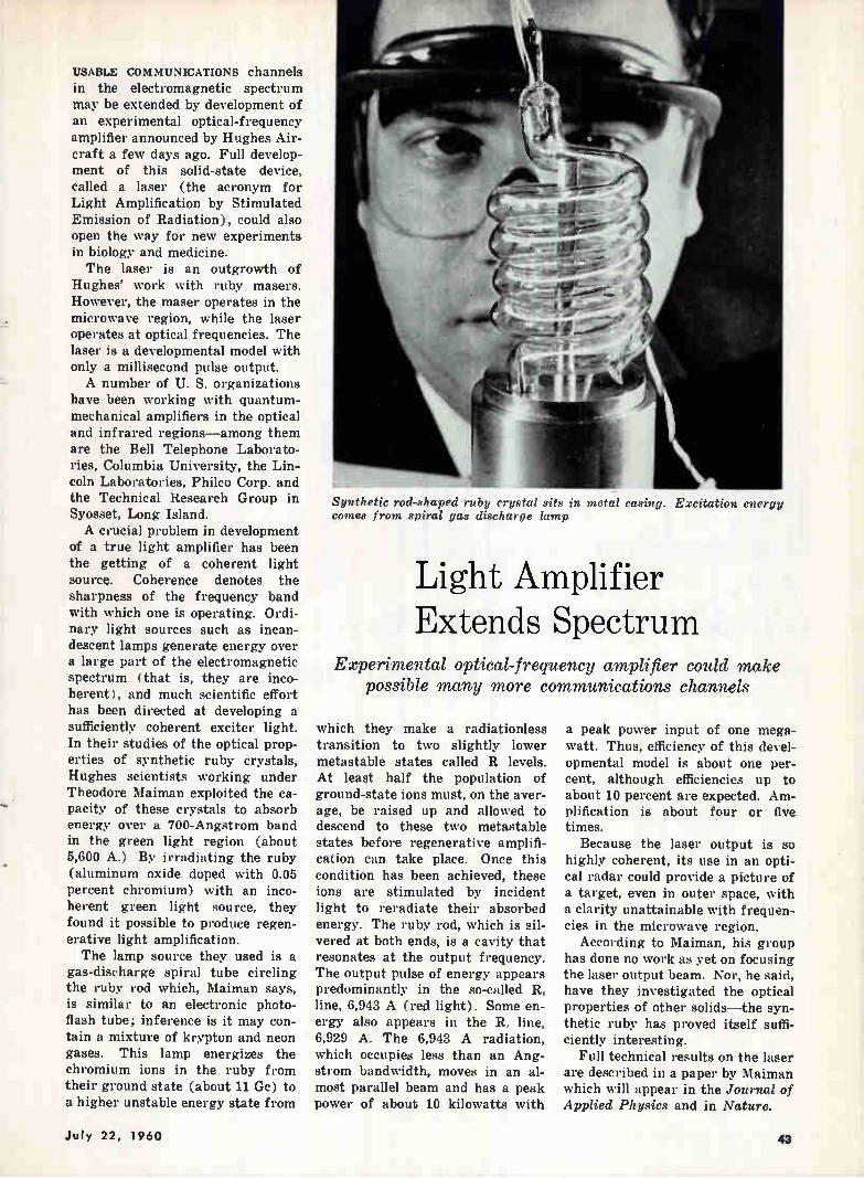
USABLE COMMUNICATIONS channels in the electromagnetic spectrum may be extended by development of an experimental optical-frequency amplifier announced by Hughes Air-craft a few days ago. Full develop-ment of this solid-state device, called a laser (the acronym for Light Amplification by Stimulated Emission of Radiation), could also open the way for new experiments in biology and medicine. The laser is an outgrowth of
Hughes' work with ruby masers. However, the maser operates in the microwave region, while the laser operates at optical frequencies. The laser is a developmental model with only a millisecond pulse output. A number of U. S. organizations
have been working with quantum-mechanical amplifiers in the optical and infrared regions—among them are the Bell Telephone Laborato-ries, Columbia University, the Lin-coln Laboratories, Phileo Corp. and the Technical Research Group in Syosset, Long Island. A crucial problem in development
of a true light amplifier has been the getting of a coherent light source. Coherence denotes the sharpness of the frequency band with which one is operating. Ordi-nary light sources such as incan-descent lamps generate energy over a large part of the electromagnetic spectrum (that is, they are inco-herent), and much scientific effort has been directed at developing a sufficiently coherent exciter light. In their studies of the optical prop-erties of synthetic ruby crystals, Hughes scientists working under Theodore Maiman exploited the ca-
-. pacity of these crystals to absorb energy over a 700-Angstrom band in the green light region (about 5,600 A.) By irradiating the ruby (aluminum oxide doped with 0.05 percent chromium) with an inco-herent green light source, they found it possible to produce regen-erative light amplification. The lamp source they used is a
gas-discharge spiral tube circling the ruby rod which, Maiman says, is similar to an electronic photo-flash tube; inference is it may con-tain a mixture of krypton and neon gases. This lamp energizes the chromium ions in the ruby from their ground state (about 11 Ge) to a higher unstable energy state from
Synthetic rod-shaped ruby crystal sits in metal casing. Excitation energy comes from spiral gas discharge lamp
Light Amplifier Extends Spectrum
Experimental optical-frequency amplifier could make possible many more communications channels
which they make a radiationless transition to two slightly lower metastable states called R levels. At least half the population of ground-state ions must, on the aver-age, be raised up and allowed to descend to these two metastable states before regenerative amplifi-cation can take place. Once this condition has been achieved, these ions are stimulated by incident light to reradiate their absorbed energy. The ruby rod, which is sil-vered at both ends, is a cavity that resonates at the output frequency. The output pulse of energy appears predominantly in the so-called It, line, 6,943 A (red light). Some en-ergy also appears in the 11, line, 6,929 A. The 6,943 A radiation, which occupies less than an Ang-strom bandwidth, moves in an al-most parallel beam and has a peak power of about 10 kilowatts with
a peak power input of one mega-watt. Thus, efficiency of this devel-opmental model is about one per-cent, although efficiencies up to about 10 percent are expected. Am-plification is about four or five times.
Because the laser output is so highly coherent, its use in an opti-cal radar could provide a picture of a target, even in outer space, with a clarity unattainable with frequen-cies in the microwave region.
According to Maiman, his group has done no work as yet on focusing the laser output beam. Nor, he said, have they investigated the optical properties of other solids—the syn-thetic ruby has proved itself suffi-ciently interesting.
Full technical results on the laser are described in a paper by Maiman which will appear in the Journal of Applied Physics and in Nature.
July 22, 1960 43
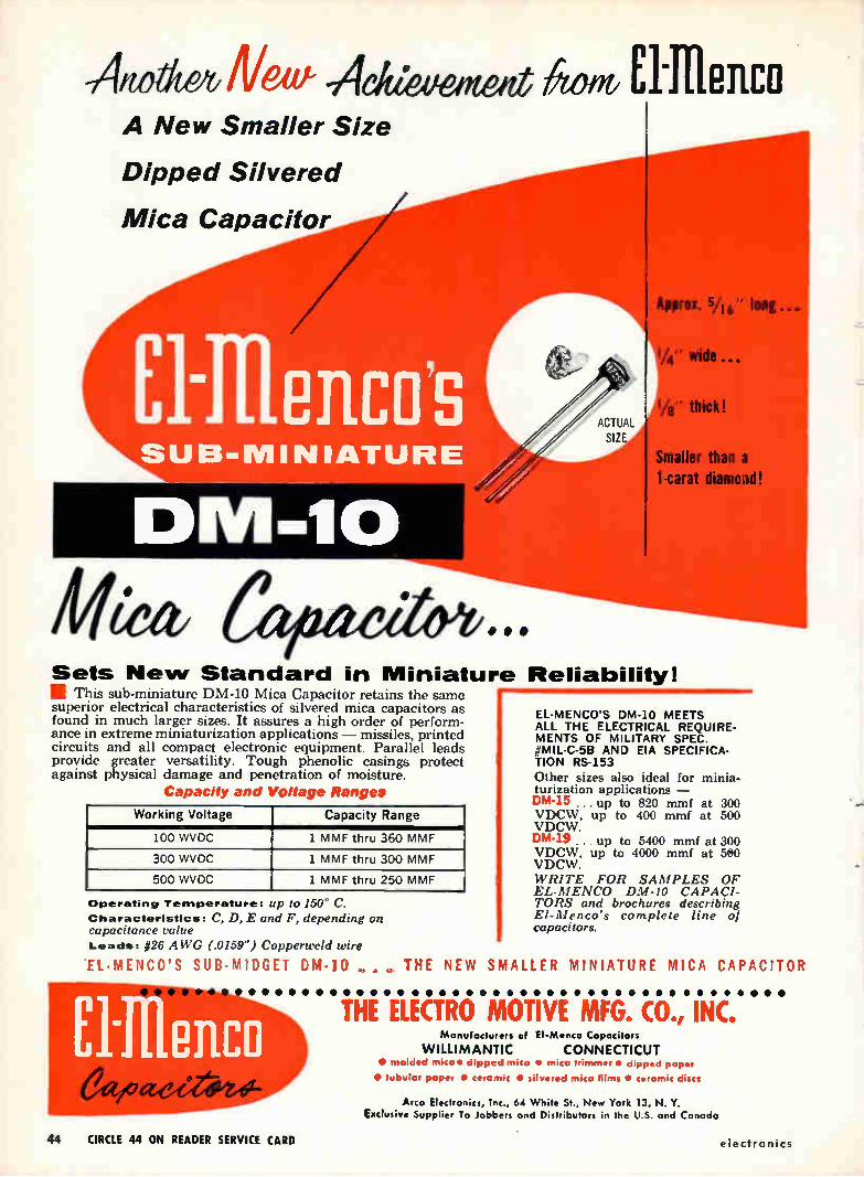
AtouteoNew Adiewigent Aim El-Illenco A New Smaller Size
Dipped Silvered
Mica Capacitor
ACTUAL
SIZE
SUB-MINIATURE
DM-10
Approx. 5/16"
1/4" wide •-•
1/8" thick!
Smaller than a 1-carat diamond!
Sets New Standard in Miniature Reliability! This sub-miniature DM-10 Mica Capacitor retains the same
superior electrical characteristics of silvered mica capacitors as found in much larger sizes. It assures a high order of perform-ance in extreme miniaturization applications — missiles, printed circuits and all compact electronic equipment. Parallel leads provide greater versatility. Tough phenolic casings protect against physical damage and penetration of moisture.
Capacity and Voltage Ranges
Working Voltage Capacity Range
100 WVDC 1 MMF thru 360 MMF
300 WVDC 1 MMF thru 300 MMF
500 WVDC 1 MMF thru 250 MMF
Operating Temperature: up to 150 - C.
Characteristics: C, D, E and F, depending on capacitance value Leads: #26 AWG (.0159") Copperweld wire
'EUMENCO'S SUB-MIDGET DM-10 •
EL-MENCO'S DM-10 MEETS ALL THE ELECTRICAL REQUIRE-MENTS OF MILITARY SPEC. MIL-C-5B AND EIA SPECIFICA-
TION RS-153
Other sizes also ideal for minia-turization applications — DM•15 ...up to 820 mrnf at 300 VDCW, up to 400 mini at 500 VDCW. DM•19 ... up to 5400 mmf at 300 VDCW, up to 4000 mmf at 5#0 VDCW. WRITE FOR SAMPLES OF EL-MENCO DM-10 CAPACI-TORS and brochures describing El-Menco's complete line of capacitors.
THE NEW SMALLER MINIATURE MICA CAPACITOR
• •• • • • • • • • • • • • • • • • • • • • • • • • • ••••..•••• co THE ELECTRO MOTIVE MFG. CO., INC.
Manufacturers of EI-Menco Capacitors
WILLIMANTIC CONNECTICUT 111 molded mica • dipped mico • mico trimmer • dipped paper
• tubular paper te ceramic • silvered mica films • ceramic discs
Arco Electronics, Inc., 64 White St., New York 13, N. Y. Exclusive Supplier To Jobbers and Distributors in the U.S. and Canada
• • •
44 CIRCLE 44 ON READER SERVICE CARD electronics
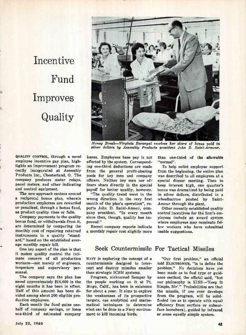
Incentive
Fund
Improves
Quality
QUALITY CONTROL, through a novel employee incentive pay plan, high-lights an improvement program re-cently inaugurated at Assembly Products Inc., Chesterland, O. The company produces meter relays, panel meters, and other indicating and control equipment. The new approach centers around
a reciprocal bonus plan, wherein production employees are rewarded or penalized, through a bonus fund, as product quality rises or falls. Company payments to the quality
bonus fund, or withdrawals from it, are determined by comparing the monthly cost of repairing returned instruments to a quality "stand-ard," based on the established aver-age monthly repair bill. One key aspect of the plan is that
it makes quality control the inti-mate concern of all production workers—not merely of engineers, inspectors and supervisory per-sonnel. The company says the plan has
saved approximately $16,600 in the eight months it has been in effect. Half of this amount has been di-vided among about 200 eligible pro-duction employees. Each month the fund gains one-
half of company savings, or loses one-third of estimated company
Money Break—Virginia Baranyai receives her share of bonus paid in silver dollars by Assembly Products president John D. Saint-Armour.
losses. Employees base pay is not affected by the system. Correspond-ing one-third deductions are made from the general profit-sharing pools for key men and company officers. Neither key men nor of-ficers share directly in the special payoff for better quality, however. "The quality trend went in the
wrong direction in the very first month of the plan's operation", re-ports John D. Saint-Amour, com-pany president. "In every month since then, though, quality has im-proved."
Recent company reports indicate a monthly repair cost slightly more
Seek Counterrnissile
NAVY is exploring the concept of a countermissile designed to inter-cept and destroy missiles smaller than strategic ICBM systems.
Program, nicknamed Semper by the people working on it at Pt. Mugu, Calif., has been in existence for about a year. It aims to explore the weaknesses of its prospective targets, use analytical and mathe-matical techniques to determine what can be done in a Navy environ-ment to kill incoming birds.
than one-third of the allowable "normal". To help enlist employee support
from the beginning, the entire plan was described to all employees at a special dinner meeting. Then to keep interest high, one quarter's bonus was dramatized by being paid in silver dollars, distributed in a wheelbarrow pushed by Saint-Amour through the plant. Other recently established quality
control incentives for the. firm's em-ployees include an award system where employees may nominate fel-low workers who have submitted usable suggestions.
For Tactical Missiles
"Our first problem," an official told ELECTRONICS, "is to define the problem." No decisions have yet been made as to fuel type or guid-ance method, the official said, "but our philosophy is KISS—'Keep It Simple, Sir'." Probabilities are that the missile, if one ever develops from the program, will be solid-fueled (so as to operate with equal efficiency from surface or subsur-face launchers), guided by infrared or some equally simple system.
July 22, 1960 45
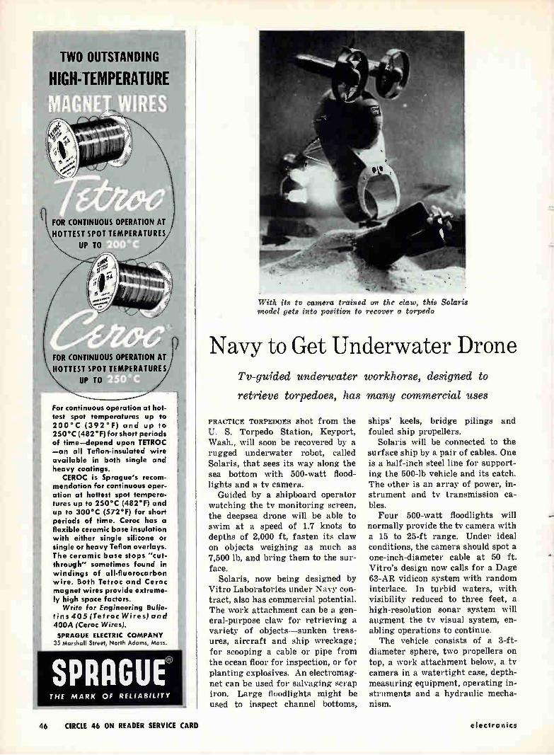
ill TWO OUTSTANDING
HIGH-TEMPERATURE -
FOR CONTINUOUS OPERATION AT HOTTEST SPOT TEMPERATURES
UP TO
FOR CONTINUOUS OPERATION AT
HOTTEST SPOT TEMPERATURES
UP TO
For continuous operation at hot-test spot temperatures up to 200°C (392°F) and up to 250°C (482°F) for short periods of time—depend upon TETROC —an all Teflon-insulated wire available in both single and heavy coatings.
CEROC is Sprague's recom-mendation for continuous oper-ation at hottest spot tempera-tures up to 250°C (482°F) and up to 300°C (572°F) for short periods of time. Ceroc has a flexible ceramic base insulation with either single silicone or single or heavy Teflon overlays. The ceramic base stops "cut-through" sometimes found in windings of all-fluorocarbon wire. Both Tetroc and Ceroc magnet wires provide extreme-ly high space factors.
Write for Engineering Bulle-
tins 405 (Tetroc Wires)and
400A (Ceroc Wires). SPRAGUE ELECTRIC COMPANY
35 Marshall Street, North Adams, Mass.
SPRAGUE® THE MARK OF RELIABILITY
With its tv camera trained on the claw, this Solaris model gets into position to recover a torpedo
Navy to Get Underwater Drone Tv-guided underwater workhorse, designed to
retrieve torpedoes, has many commercial uses
PRACTICE TORPEDOES shot from the U. S. Torpedo Station, Keyport, Wash., will soon be recovered by a rugged underwater robot, called Solaris, that sees its way along the sea bottom with 500-watt flood-lights and a tv camera.
Guided by a shipboard operator watching the tv monitoring screen, the deepsea drone will be able to swim at a speed of 1.7 knots to depths of 2,000 ft, fasten its claw on objects weighing as much as 7,500 lb, and bring them to the sur-face.
Solaris, now being designed by Vitro Laboratories under Navy con-tract, also has commercial potential. The work attachment can be a gen-eral-purpose claw for retrieving a variety of objects—sunken treas-ures, aircraft and ship wreckage; for scooping a cable or pipe from the ocean floor for inspection, or for planting explosives. An electromag-net can be used for salvaging scrap iron. Large floodlights might be used to inspect channel bottoms,
ships' keels, bridge pilings and fouled ship propellers.
Solaris will be connected to the surface ship by a pair of cables. One is a half-inch steel line for support-ing the 500-lb vehicle and its catch. The other is an array of power, in-strument and tv transmission ca-bles. Four 500-watt floodlights will
normally provide the tv camera with a 15 to 25-ft range. Under ideal conditions, the camera should spot a one-inch-diameter cable at 50 ft. Vitro's design now calls for a Dage 63-AR vidicon system with random interlace. In turbid waters, with visibility reduced to three feet, a high-resolution sonar system will augment the tv visual system, en-abling operations to continue. The vehicle consists of a 3-ft-
diameter sphere, two propellers on top, a work attachment below, a tv camera in a watertight case, depth-measuring equipment, operating in-struments and a hydraulic mecha-nism.
46 CIRCLE 46 ON READER SERVICE CARD electronics
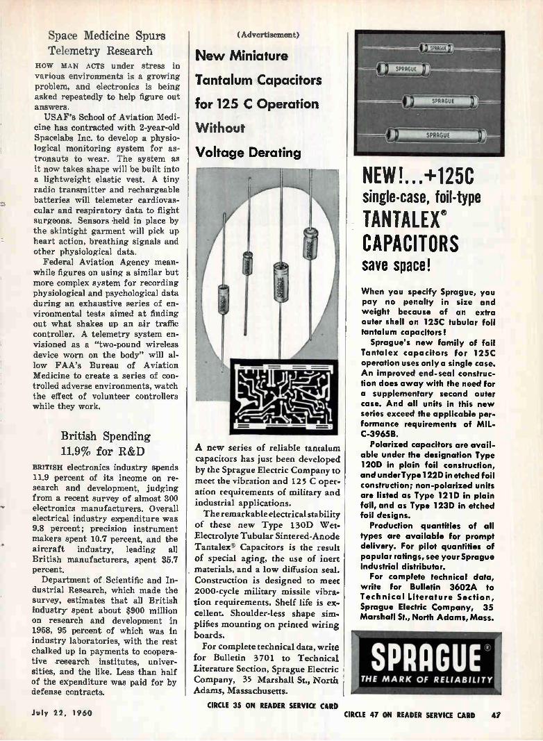
.er
Space Medicine Spurs Telemetry Research
HOW MAN ACTS under stress in various environments is a growing problem, and electronics is being asked repeatedly to help figure out answers. USAF's School of Aviation Medi-
cine has contracted with 2-year-old Spacelabs Inc. to develop a physio-logical monitoring system for as-tronauts to wear. The system as it now takes shape will be built into a lightweight elastic vest. A tiny radio transmitter and rechargeable batteries will telemeter cardiovas-cular and respiratory data to flight surgeons. Sensors held in place by the skintight garment will pick up heart action, breathing signals and other physiological data.
Federal Aviation Agency mean-while figures on using a similar but more complex system for recording physiological and psychological data during an exhaustive series of en-vironmental tests aimed at finding out what shakes up an air traffic controller. A telemetry system en-visioned as a "two-pound wireless device worn on the body" will al-low FAA's Bureau of Aviation Medicine to create a series of con-trolled adverse environments, watch the effect of volunteer controllers while they work.
British Spending 11.9% for R&D
BRITISH electronics industry spends 11.9 percent of its income on re-search and development, judging from a recent survey of almost 300 electronics manufacturers. Overall electrical industry expenditure was 9.8 percent; precision instrument makers spent 10.7 percent, and the aircraft industry, leading all British manufacturers, spent 35.7 percent. Department of Scientific and In-
dustrial Research, which made the survey, estimates that all British industry spent about $900 million on research and development in 1958, 95 percent of which was in industry laboratories, with the rest chalked up in payments to coopera-tive research institutes, univer-sities, and the like. Less than half of the expenditure was paid for by defense contracts.
(Advertisement)
New Miniature
Tantalum Capacitors
for 125 C Operation
Without
Voltage Derating
A new series of reliable tantalum capacitors has just been developed by the Sprague Electric Company to meet the vibration and 125 C oper-ation requirements of military and industrial applications. The remarkable electrical stability
of these new Type 130D Wet-Electrolyte Tubular Sintered-Anode Tantalee Capacitors is the result of special aging, the use of inert materials, and a low diffusion seal. Construction is designed to meet 2000-cycle military missile vibra-tion requirements. Shelf life is ex-cellent. Shoulder-less shape sim• plifies mounting on printed wiring boards.
For complete technical data, write for Bulletin 3701 to Technical Literature Section, Sprague Electric Company, 35 Marshall St., North Adams, Massachusetts.
11,M1131
IMI10=1111111,i
nitmenum L., .
NEW!.. .-'-125C single-case, foil-type
TANTALEX9 CAPACITORS save space!
When you specify Sprague, you pay no penalty in size and weight because of an extra outer shell on 125C tubular foil tantalum capacitors!
Sprague's new family of foil Tantalex capacitors for 125C operation uses only a single case. An improved end-seal construc-tion does away with the need for a supplementary second outer case. And all units in this new series exceed the applicable per-formance requirements of MIL-C-39658.
Polarized capacitors are avail-able under the designation Type 120D in plain foil construction, and under Type 122D in etched foil construction; non-polarized units are listed as Type 121D in plain fail, and as Type 123D in etched foil designs.
Production quantities of all types are available for prompt delivery. For pilot quantities of popular ratings, see your Sprague industrial distributor.
For complete technical data, write for Bulletin 3602A to Technical Literature Section, Sprague Electric Company, 35 Marshall St., North Adams, Mass.
July 22, 1960 CIRCLE 35 ON READER SERVICE CUD
CIRCLE 47 ON READER SERVICE CARD 4i
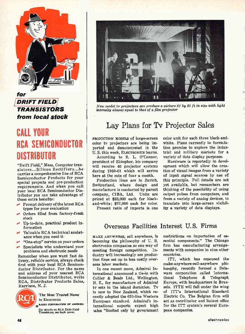
for
'DRIFT FIELD/ TRANSISTORS
from local stock
CALL YOUR RCA SEMICONDUCTOR DISTRIBUTOR "Drift Field," Mesa, Computer tran-sistors...Silicon Rectifiers...he carries a comprehensive line of RCA Semiconductor Products for your special projects and pre-production requirements. And when you call your local RCA Semiconductor Dis-tributor you can take advantage of these extra benefits:
Prompt delivery of the latest RCA types for your evaluation
v Orders filled from factory-fresh stock
v• Up-to-date, practical product in-formation
po Valuable RCA technical assist-ance when you need it "One-stop" service on your orders
to• Specialists who understand your problems and electronic needs
Remember when you want fast de-livery, reliable service, always check first with your local RCA Semicon-ductor Distributor. For the name and address of your nearest RCA Semiconductor Distributor, write RCA, Distributor Products Sales, Harrison, N. J.
del% The Most Trusted Name in Electronics
¡elk e RADIO CORPORATION OF AMERICA
For details on RCA Drift-Field Transistors, see back cover.
New model tv projectors can produce a picture 23 by 32 ft in size with light intensity almost equal to that of a film projector
Lay Plans for Tv Projector Sales
PRODUCTION MODELS of large-screen color tv projectors are being im-ported and demonstrated in the U. S. this week, ELECTRONICS learns.
According to R. L. O'Connor, president of Eidophor, his company will receive 40 projector systems during 1960-61 which will arrive here at the rate of four a month.
Production lines are in Zurich, Switzerland, where design and manufacture is conducted by parent company, CIBA, Ltd. Units are priced at $23,000 each for black-and-white; $27,000 each for color.
Present ratio of imports is one
color unit for each three black-and-white. Plans currently in formula-tion promise to explore the indus-trial and military markets for a variety of data display purposes. Hardware is reportedly in devel-
opment which will allow the crea-tion of visual images from a variety of input signal sources by use of this principle. Full details are not yet available, but researchers are thinking of the possibility of using output pulses from computers, and from a variety of analog devices, to translate into large-screen visibil-ity a variety of data displays.
Overseas Facilities Interest U. S. Firms
MAKE ANYWHERE, sell anywhere, is becoming the philosophy of U. S. electronics companies as one way of meeting foreign competition. In-dustry will increasingly see produc-tion lines set up in less costly over-seas labor markets.
In one recent move, Admiral In-ternational announced a tie-in with Collier & Beals Ltd., Wellington, N. Z., for manufacture of Admiral tv sets in the island dominion. Tv is new to New Zealand, which re-cently adopted the 625-line Western European standard. Admiral's in-ternational experts expect high gales "limited only by government
restrictions on importation of es-sential components." The Chicago firm has manufacturing arrange-ments with companies in nine other countries.
ITT, which has espoused the make-anywhere-sell-anywhere phi-losophy, recently formed a Dela-ware corporation called Interna-tional Telephone & Telegraph Europe, with headquarters in Brus-sels. ITTE will fall under the wing of ITT's International Standard Electric Co. The Belgian firm will act as coordinator and liaison office for the ITT system's several Euro-pean companies.
48 electronics
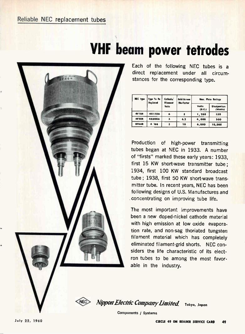
Reliable NEC replacement tubes
VHF beam power tetrodes Each of the following NEC tubes is a
direct replacement under all circum-stances for the corresponding type.
NEC type Type To Be
Replaced
Cathode
Filament
Volts
Grid-Screen
Mu-Factor
Max. Plate Ratings
Volts
(D.C.) Dissipation
(Watts)
4F1SR 4X150A 6 5 1, 250 150
6F5OR 4X500A 5 6.2 4 , 000 500
8F66R 6 166 5 10 6,000 10,000
Production of high-power transmitting
tubes began at NEC in 1933. A number
of "firsts" marked these early years: 1933,
first 15 KW short-wave transmitter tube ;
1934, first 100 KW standard broadcast
tube ; 1938, first 50 KW short-wave trans-
mitter tube. In recent years, NEC has been
following designs of U.S. Manufactures and
concentrating on improving tube life.
The most important improvements have
been a new doped-nickel cathode material
with high emission at low oxide evapora-
tion rate, and non-sag thoriated tungsten
filament material which has completely
eliminated filament-grid shorts. NEC con-
siders the life characteristic of its elect-
ron tubes to be among the most favor-
able in the industry.
Neon Electric Company limited:
Components J Systems
Tokyo, Japan
July 22, 1960 CIRCLE 49 ON READER SERVICE CARD 49
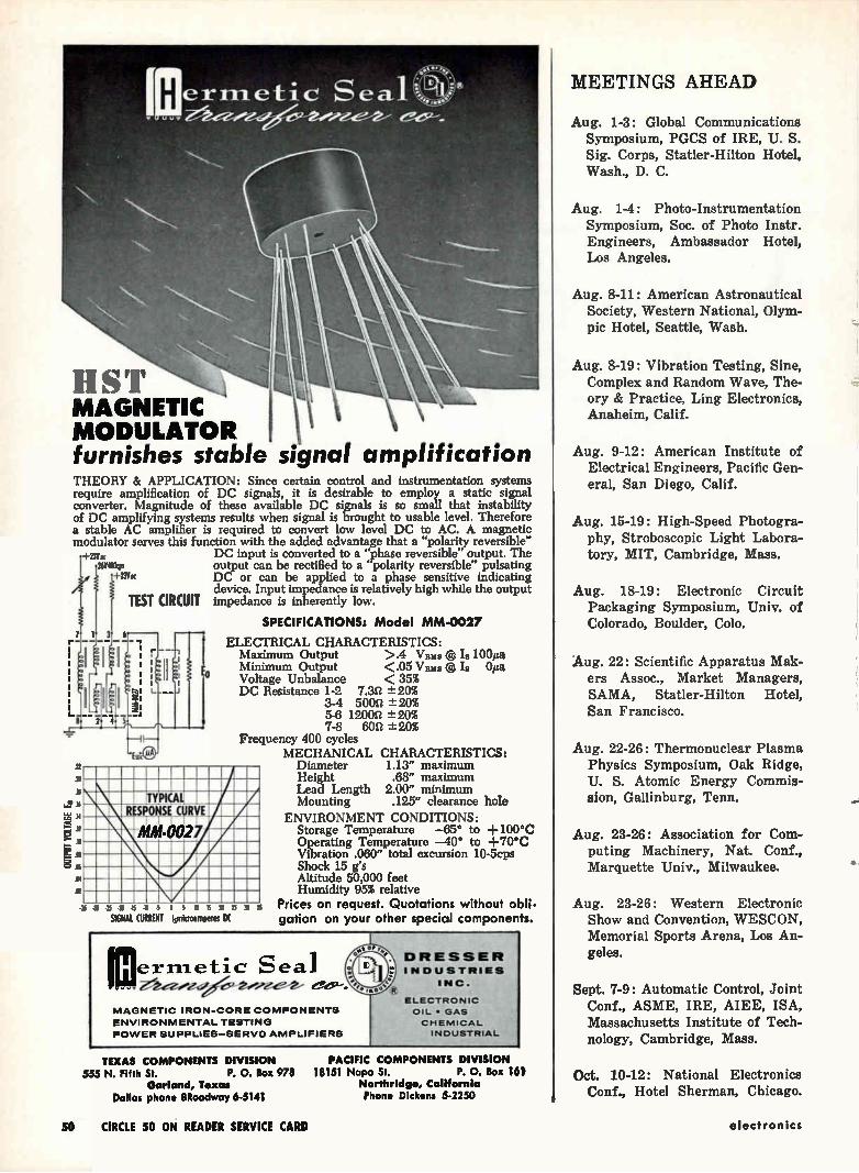
MAGNETIC MODULATOR furnishes stable signal amplification THEORY & APPLICATION: Since certain control and instrumentation systems require amplification of DC signals, it is desirable to employ a static signal converter. Magnitude of these available DC signals is so small that instability of DC amplifying systems results when signal is brought to usable level. Therefore a stable AC amplifier is required to convert low level DC to AC. A magnetic modulator serves this function with the added advantage that a "polarity reversible"
-Fz3v:s DC input is converted to a "phase reversible" output. The 26Y4Okps output can be rectified to a polarity reversible" pulsating
-FZIVot DC or can be applied to a phase sensitive indicating device. Input impedance is relatively high while the output
TEST CIRCUIT impedance is inherently low.
SPECIFICATIONS: Model MM-0027
ELECTRICAL CHARACTERISTICS: Maximum Output >.4 Vitus @ Is 100µa Minimum Output <.05 Vini3 ® Is Oita
Voltage Unbalance < 35% DC Resistance 1-2 7.32 -± 20%
3-4 5002 ± 20% 5-6 12002 -± 20% 7-8 son -± 20%
Frequency 400 cycles MECHANICAL CHARACTERISTICS:
Diameter 1.13" maximum Height .68" maximum Lead Length 2.00" minimum Mounting .125" clearance hole
ENVIRONMENT CONDITIONS: Storage Temperature —65° to +100°C Operating Temperature —40° to +70°C Vibration .060" total excursion 10-5cps Shock 15 g's Altitude 50,000 feet Humidity 95% relative
Prices on request. Quotations without obli-gation on your other special components.
ITYPICAL RESPONS COMM MM-0027
51 45 41 .5 5 1 5 3 5 5 a 35
SIGNAL CURRENT lsmicroomperes DI
Irnermetic Seal MAGNETIC IRON-CORE COMPONENTS
ENVIRONMENTAL TESTING
POWER SUPPLIES—SERVO AMPLIFIERS
DRESSER INDUSTRIES
INC. e *
ELECTRONIC
OIL • GAS
CHEMICAL INDUSTRIAL
TEXAS COMPONENTS DIVISION 555 N. Fifth St. P. 0, Box 978
Garland, Texas Dallas phone BRoadway 6-5141
PACIFIC COMPONENTS DIVISION 18151 Napa St. P. 0. Box 161
Northridge, California Phone Dickens 5-2250
MEETINGS AHEAD
Aug. 1-3: Global Communications
Symposium, PGCS of IRE, U. S.
Sig. Corps, Statler-Hilton Hotel,
Wash., D. C.
Aug. 1-4: Photo-Instrumentation
Symposium, Soc. of Photo Instr.
Engineers, Ambassador Hotel,
Los Angeles,
Aug. 8-11: American Astronautical
Society, Western National, Olym-
pic Hotel, Seattle, Wash.
Aug. 8-19: Vibration Testing, Sine,
Complex and Random Wave, The-
ory & Practice, Ling Electronics,
Anaheim, Calif.
Aug. 9-12: American Institute of
Electrical Engineers, Pacific Gen-
eral, San Diego, Calif.
Aug. 15-19: High-Speed Photogra-
phy, Stroboscopic Light Labora-
tory, MIT, Cambridge, Mass.
Aug. 18-19: Electronic Circuit
Packaging Symposium, Univ. of
Colorado, Boulder, Colo.
Aug. 22: Scientific Apparatus Mak-
ers Assoc., Market Managers,
SAMA, Statler-Hilton Hotel,
San Francisco.
Aug. 22-26: Thermonuclear Plasma
Physics Symposium, Oak Ridge,
U. S. Atomic Energy Commis-
sion, Gallinburg, Tenn.
Aug. 23-26: Association for Com-
puting Machinery, Nat. Conf.,
Marquette Univ., Milwaukee.
Aug. 23-26: Western Electronic
Show and Convention, WESCON,
Memorial Sports Arena, Los An-
geles.
Sept. 7-9: Automatic Control, Joint
Conf., ASME, IRE, AIEE, ISA,
Massachusetts Institute of Tech-
nology, Cambridge, Mass.
Oct. 10-12: National Electronics
Conf., Hotel Sherman, Chicago.
50 CIRCLE 50 ON READER SERVICE CARD electronics
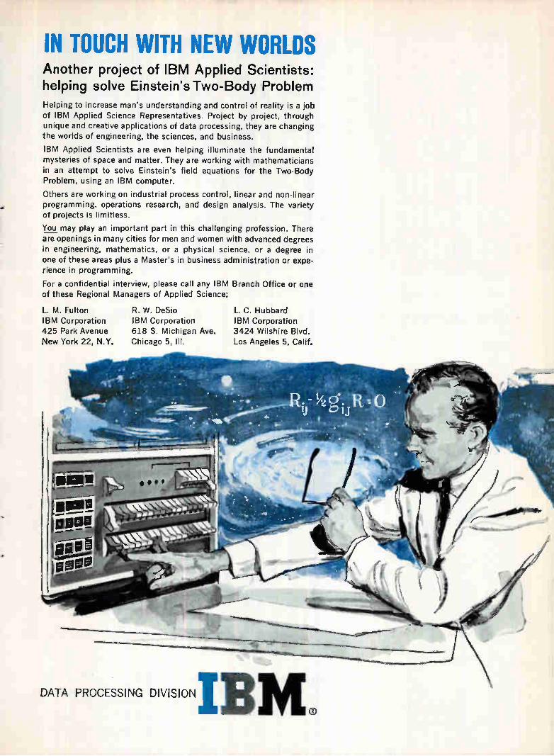
IN TOUCH WITH NEW WORLDS Another project of IBM Applied Scientists: helping solve Einstein's Two-Body Problem Helping to increase man's understanding and control of reality is a job of IBM Applied Science Representatives. Project by project, through unique and creative applications of data processing, they are changing the worlds of engineering, the sciences, and business.
IBM Applied Scientists are even helping illuminate the fundamental mysteries of space and matter. They are working with mathematicians in an attempt to solve Einstein's field equations for the Two-Body Problem, using an IBM computer.
Others are working on industrial process control, linear and non-linear programming, operations research, and design analysis. The variety of projects is limitless.
You may play an important part in this challenging profession. There are openings in many cities for men and women with advanced degrees
in engineering, mathematics, or a physical science, or a degree in one of these areas plus a Master's in business administration or expe-rience in programming.
For a confidential interview, please call any IBM Branch Office or one of these Regional Managers of Applied Science:
L. M. Fulton IBM Corporation 425 Park Avenue New York 22, N.Y.
R. W. DeSio IBM Corporation 618 S. Michigan Ave. Chicago 5, III.
L. C. Hubbard IBM Corporation 3424 Wilshire Blvd. Los Angeles 5, Calif.
DATA PROCESSING DIVISION IBM
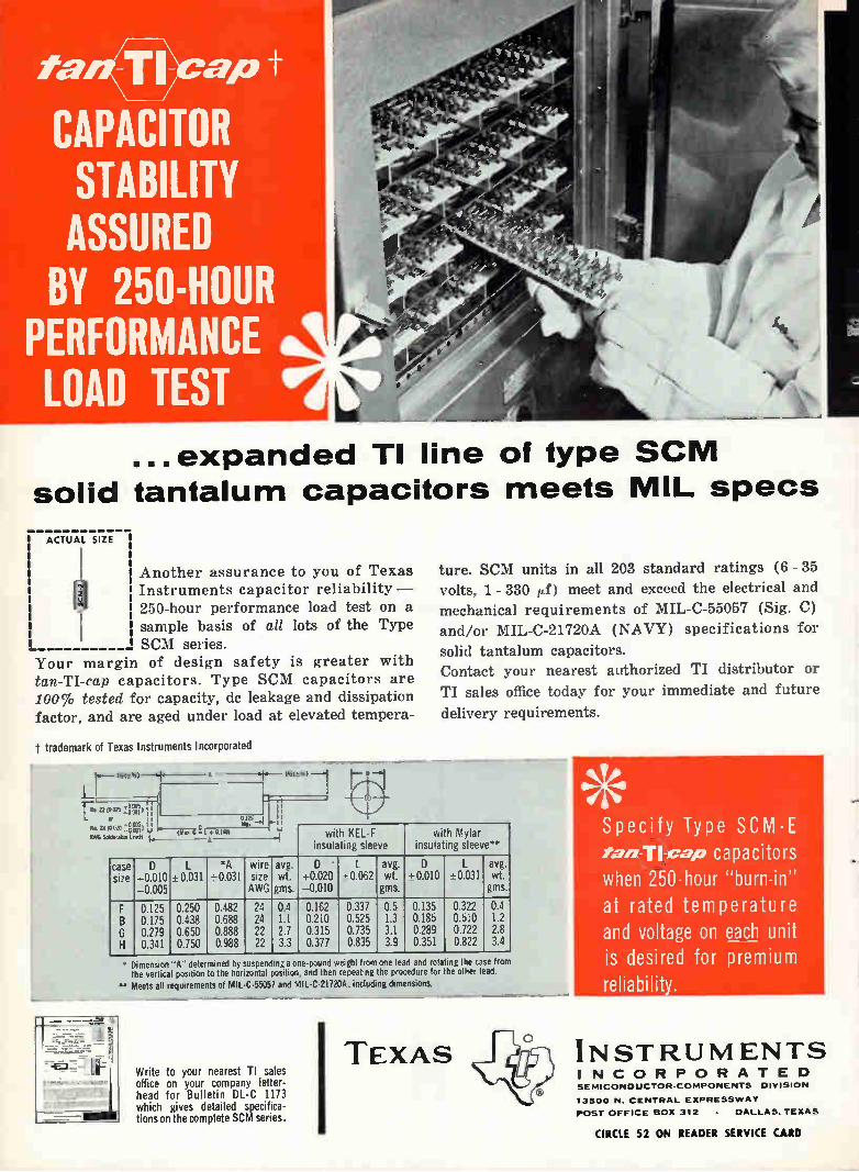
ta apt
CAPACITOR STABILITY ASSURED BY 250-HOUR
PERFORMANCE LOAD TEST
...expanded TI line of type SCM
solid tantalum capacitors meets MIL specs
ACTUAL SIZE
Another assurance to you of Texas Instruments capacitor reliability - 250-hour performance load test on a sample basis of all lots of the Type SCM series.
Your margin of design safety is greater with tan-TI-cap capacitors. Type SCM capacitors are 100% tested for capacity, de leakage and dissipation factor, and are aged under load at elevated tempera-
T trademark of Texas Instruments Incorporated
tore. SCM units in all 203 standard ratings (6 - 35 volts, 1 - 330 ,d) meet and exceed the electrical and mechanical requirements of MIL-C-55057 (Sig. C) and/or MIL-C-21720A (NAVY) specifications for
solid tantalum capacitors. Contact your nearest authorized TI distributor or
TI sales office today for your immediate and future
delivery requirements.
lv,(3 4,)
t ( F7p0 '22 (002S • D'')
N.04;02OYi'd AVAG Seldeeatee lees I
ot0,C E L 0 140) A
with KEL-F insulating sleeve
wi h Mylar insulating sleeve**
case size
D 0.010
-0.005 t- 0.031
*A wire -• 0.031 size
AWG
avg. wt. gms.
0.020 -0.010
• 0.062 avg. wt. gms.
D - 0.010 0.031
avg. wt. gms.
G H
0.125 0.175 0.279 0.341
0.250 0.438 0.650 0.750
0.482 0.688 0.888 0.988
24 24 22 22
0.4 1.1 2.7 3.3
0.162 0.210 0.315 0.377
0.337 0.525 0.735 0.835
0.5 1.3 3.1 3.9
0.135 0.185 0.289 0.351
0.322 0.510 0.722 0.822
0.4 1.2 2.8 3.4
• Dimension "A" determined by suspending a one-pound weight from one lead and rota ing the case from the vertical position o the horizontal position, and then repeating he procedure for he other lead.
** Meets all requirements of MIL-C-55057 and MIL-C-21720k including dimensions.
1 Write to your nearest TI sales
office on your company letter-head for Bulletin DL-C 1173 which gives detailed specifica-tions on the complete SCM series.
I TEXAS
Specify Type SCM-E ranlicap capacitors when 250-hour "burn-in" at rated temperature and voltage on each unit is desired for premium reliability.
INSTRUMENTS INCORPORATED SEMICONDUCTOR-COMPONENTS DIVISION
13500 N. CENTRAL EXPRESSWAY
POST OFFICE BOX 312 • DALLAS. TEXA5
CIRCLE 52 ON READER SERVICE CARD
•i
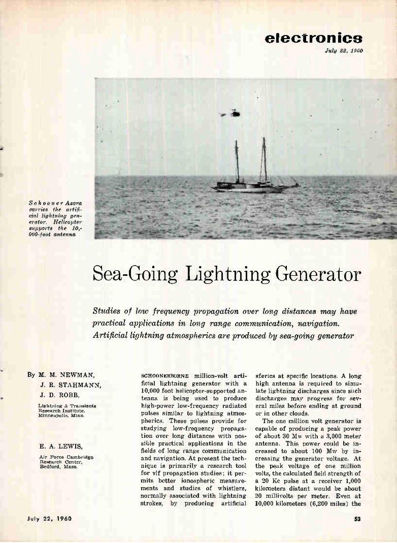
electronics July 22, 1960
s.
Schooner Azara carries the artifi-cial lightning gen-erator. Helicopter supports the 10,-000-foot antenna
• _
r e- 44, •
*0-
-- ;W.
t
Qt-.• • ,
• , •-"ttor.- •
• '•+*> *— * _
. „drew.. , • -• - _
414,.....111111.10100e • +re... •••• »lelit"nedf14 •
Sea-Going Lightning Generator
Studies of low frequency propagation over long distances may have
practical applications in long range communication, navigation.
Artificial lightning atmospherics are produced by sea-going generator
By M. M. NEWMAN,
J. R. STAHMANN,
J. D. ROBB,
Lightning & Transients Research Institute, Minneapolis, Minn.
E. A. LEWIS,
Air Force Cambridge Research Center, Bedford, Mass.
SCHOONERBORNE million-volt arti-ficial lightning generator with a 10,000 foot helicopter-supported an-tenna is being used to produce high-power low-frequency radiated pulses similar to lightning atmos-pherics. These pulses provide for studying low-frequency propaga-tion over long distances with pos-sible practical applications in the fields of long range communication and navigation. At present the tech-nique is primarily a research tool for vif propagation studies; it per-mits better ionospheric measure-ments and studies of whistlers, normally associated with lightning strokes, by producing artificial
sferics at specific locations. A long high antenna is required to simu-late lightning discharges since such discharges may progress for sev-eral miles before ending at ground or in other clouds. The one million volt generator is
capable of producing a peak power of about 30 Mw with a 3,000 meter antenna. This power could be in-creased to about 100 Mw by in-creasing the generator voltage. At the peak voltage of one million volts, the calculated field strength of a 20 Kc pulse at a receiver 1,000 kilometers distant would be about 20 millivolts per meter. Even at 10,000 kilometers (6,200 miles) the
".. -1••
- -
July 22, 1960 se
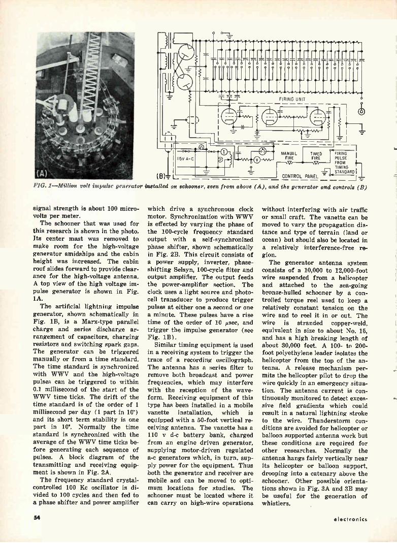
0 0 0 j 00 1: o
o o o O
o— f
FIRING UNIT
II5V A-C MANUAL TIMED FIRING I
FIRE FIRE PULSE ' ‘V• V FROM
TIMING , —1-I... STANDARD I
CONTROL PANEL -
FIG. 1—Million volt impulse generator installed on schooner, seen from above (A), and the generator and controls (B)
signal strength is about 100 micro-volts per meter. The schooner that was used for
this research is shown in the photo. Its center mast was removed to make room for the high-voltage generator amidships and the cabin height was increased. The cabin roof slides forward to provide clear-ance for the high-voltage antenna. A top view of the high voltage im-pulse generator is shown in Fig. 1A. The artificial lightning impulse
generator, shown schematically in Fig. 1B, is a Marx-type parallel charge and series discharge ar-rangement of capacitors, charging resistors and switching spark gaps. The generator can be triggered manually or from a time standard. The time standard is synchronized with WWV and the high-voltage pulses can be triggered to within 0.1 millisecond of the start of the WWV time ticks. The drift of the time standard is of the order of 1 millisecond per day (1 part in 10") and its short term stability is one part in 109. Normally the time standard is synchronized with the average of the WWV time ticks be-fore generating each sequence of pulses. A block diagram of the transmitting and receiving equip-ment is shown in Fig. 2A. The frequency standard crystal-
controlled 100 Kc oscillator is di-vided to 100 cycles and then fed to a phase shifter and power amplifier
which drive a synchronous clock motor. Synchronization with WWV is effected by varying the phase of the 100-cycle frequency standard output with a self-synchronized phase shifter, shown schematically in Fig. 2B. This circuit consists of a power supply, inverter, phase-shifting Selsyn, 100-cycle filter and output amplifier. The output feeds the power-amplifier section. The clock uses a light source and photo-cell transducer to produce trigger pulses at either one a second or one a minute. These pulses have a rise time of the order of 10 µsec, and trigger the impulse generator (see Fig. 1B).
Similar timing equipment is used in a receiving system to trigger the trace of a recording oscillograph. The antenna has a series filter to remove both broadcast and power frequencies, which may interfere with the reception of the wave-form. Receiving equipment of this type has been installed in a mobile vanette installation, which is equipped with a 50-foot vertical re-ceiving antenna. The vanette has a 110 y d-c battery bank, charged from an engine driven generator, supplying motor-driven regulated a-c generators which, in turn, sup-ply power for the equipment. Thus both the generator and receiver are mobile and can be moved to opti-mum locations for studies. The schooner must be located where it can carry on high-wire operations
without interfering with air traffic or small craft. The vanette can be moved to vary the propagation dis-tance and type of terrain (land or ocean) but should also be located in a relatively interference-free re-gion. The generator antenna system
consists of a 10,000 to 12,000-foot wire suspended from a helicopter and attached to the sea-going bronze-hulled schooner by a con-trolled torque reel used to keep a relatively constant tension on the wire and to reel it in or out. The wire is stranded copper-weld, equivalent in size to about No. 15, and has a high breaking length of about 30,000 feet. A 100- to 200-foot polyethylene leader isolates the helicopter from the top of the an-tenna. A release mechanism per-mits the helicopter pilot to drop the wire quickly in an emergency situa-tion. The antenna current is con-tinuously monitored to detect exces-sive field gradients which could result in a natural lightning stroke to the wire. Thunderstorm con-ditions are avoided for helicopter or balloon supported antenna work but these conditions are required for other researches. Normally the antenna hangs fairly vertically near its helicopter or balloon support, drooping into a catenary above the schooner. Other possible orienta-tions shown in Fig. 3A and 3B may be useful for the generation of whistlers.
le•
54 electronics
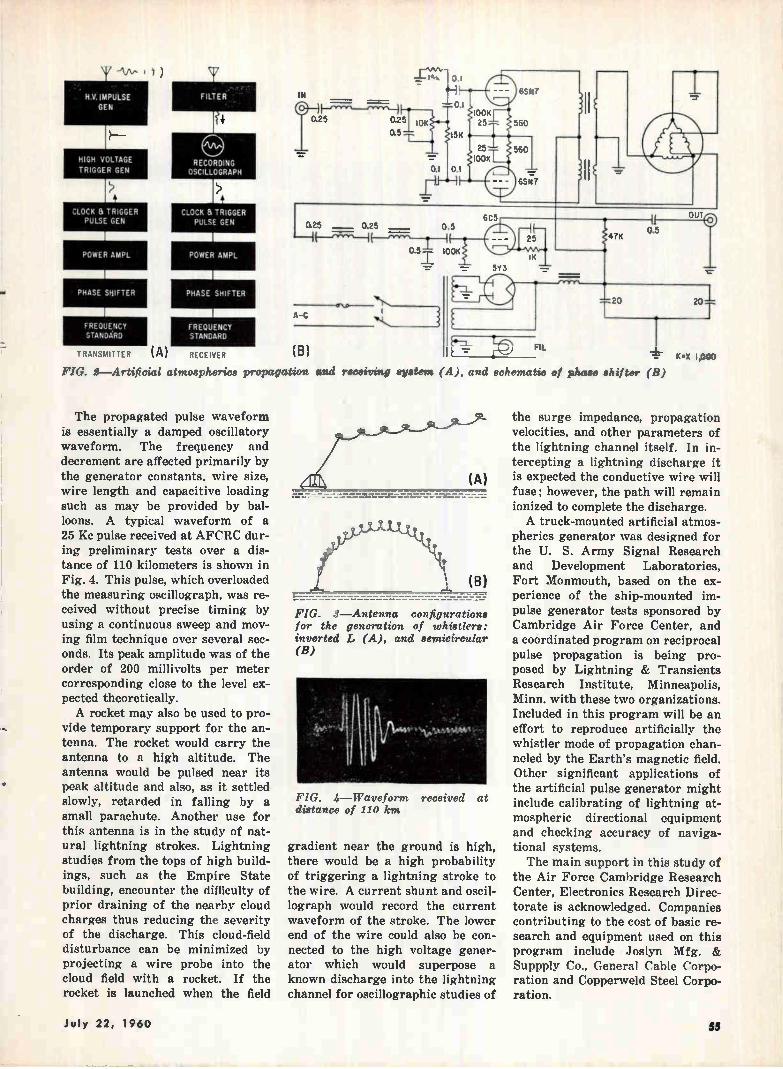
NV. IMPULSE
GEN
H-
HIGH VOLTAGE
TRIGGER GEN
CLOCK & TRIGGER PULSE GEN
POWER AMPL
1
PHASE SHIFTER
1 FREQUENCY STANDARD
TRANSMITTER (A)
FILTER .
CLOCK a TRIGGER PULSE GEN
1
POWER AMPL
1
PHASE SHIFTER
FREQUENCY STANDARD
RECEIVER
IN r.25 0.5
°•251 OK
-r
F.----_,--,H1
,-0.1
0.;
O.'
15V
0.1
OOK 25
6357
560
25
100K 560
65N7
0.25
A-C
025 0.5
‘-11-- 05 100K
1-
(B) FIG. 2—Artificial atmospherics propagation and
The propagated pulse waveform is essentially a damped oscillatory waveform. The frequency and decrement are affected primarily by the generator constants, wire size, wire length and capacitive loading such as may be provided by bal-loons. A typical waveform of a 25 Kc pulse received at AFCRC dur-ing preliminary tests over a dis-tance of 110 kilometers is shown in Fig. 4. This pulse, which overloaded the measuring oscillograph, was re-ceived without precise timing by using a continuous sweep and mov-ing film technique over several sec-onds. Its peak amplitude was of the order of 200 millivolts per meter corresponding close to the level ex-pected theoretically. A rocket may also be used to pro-
vide temporary support for the an-tenna. The rocket would carry the antenna to a high altitude. The antenna would be pulsed near its peak altitude and also, as it settled slowly, retarded in falling by a small parachute. Another use for this antenna is in the study of nat-ural lightning strokes. Lightning studies from the tops of high build-ings, such as the Empire State building, encounter the difficulty of prior draining of the nearby cloud charges thus reducing the severity of the discharge. This cloud-field disturbance can be minimized by projecting a wire probe into the cloud field with a rocket. If the rocket is launched when the field
receiving
6C5
5Y3
HH 25
1 FIL
20
1 0.5
UT
20
system (A), and schematic of phase shifter (B)
FIG. 3—Antenna configurations for the generation of whistlers: inverted L (A), and semicircular (B)
FIG. 4—Waveform received at distance of 110 km
gradient near the ground is high, there would be a high probability of triggering a lightning stroke to the wire. A current shunt and oscil-lograph would record the current waveform of the stroke. The lower end of the wire could also be con-nected to the high voltage gener-ator which would superpose a known discharge into the lightning channel for oscillographic studies of
('X 1,000
the surge impedance, propagation velocities, and other parameters of the lightning channel itself. In in-tercepting a lightning discharge it is expected the conductive wire will fuse; however, the path will remain ionized to complete the discharge. A truck-mounted artificial atmos-
pherics generator was designed for the U. S. Army Signal Research and Development Laboratories, Fort Monmouth, based on the ex-perience of the ship-mounted im-pulse generator tests sponsored by Cambridge Air Force Center, and a coordinated program on reciprocal pulse propagation is being pro-posed by Lightning & Transients Research Institute, Minneapolis, Minn. with these two organizations. Included in this program will be an effort to reproduce artificially the whistler mode of propagation chan-neled by the Earth's magnetic field. Other significant applications of the artificial pulse generator might include calibrating of lightning at-mospheric directional equipment and checking accuracy of naviga-tional systems. The main support in this study of
the Air Force Cambridge Research Center, Electronics Research Direc-torate is acknowledged. Companies contributing to the cost of basic re-search and equipment used on this program include Joslyn Mfg. & Suppply Co., General Cable Corpo-ration and Copperweld Steel Corpo-ration.
July 22, 1960 55
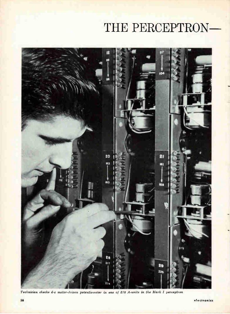
L , ,‘N a elyziepore -1, ,e;- -
;E•.• - ...— . dt .-11'... -1..
- .. ..... — . — --- • . 10 1
Technician checks cl-c motor-driven potentiometer in one of 512 A-units in the Mark I perceptron
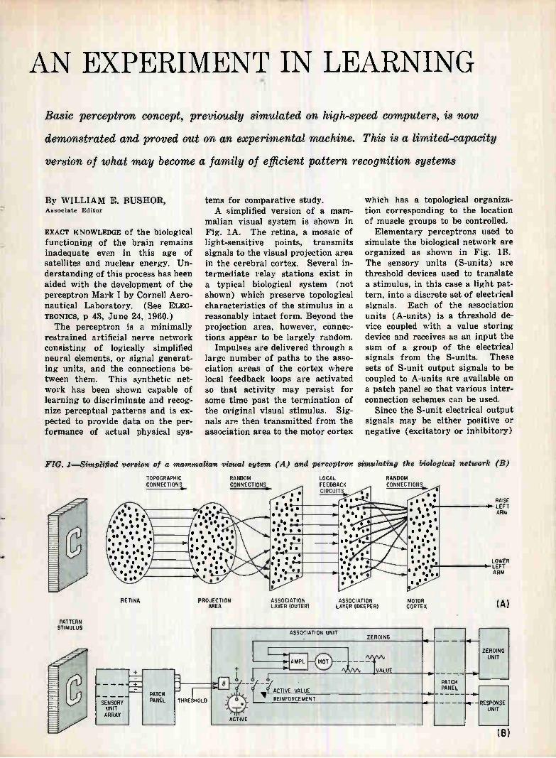
AN EXPERIMENT IN LEARNING
Basic perceptron concept, previously simulated on high-speed computers, is now
demonstrated and proved out on an experimental machine. This is a limited-capacity
version of what may become a family of efficient pattern recognition systems
By WILLIAM E. BUSHOR, Associate Editor
EXACT KNOWLEDGE of the biological functioning of the brain remains inadequate even in this age of satellites and nuclear energy. Un-derstanding of this process has been aided with the development of the perceptron Mark I by Cornell Aero-nautical Laboratory. (See ELEC-TRONICS, p 43, June 24, 1960.) The perceptron is a minimally
restrained artificial nerve network consisting of logically simplified neural elements, or signal generat-ing units, and the connections be-tween them. This synthetic net-work has been shown capable of learning to discriminate and recog-nize perceptual patterns and is ex-pected to provide data on the per-formance of actual physical sys-
FIG.
PATTERN STIMULUS
tems for comparative study. A simplified version of a mam-
malian visual system is shown in Fig. 1A. The retina, a mosaic of light-sensitive points, transmits signals to the visual projection area in the cerebral cortex. Several in-termediate relay stations exist in a typical biological system (not shown) which preserve topological characteristics of the stimulus in a reasonably intact form. Beyond the projection area, however, connec-tions appear to be largely random.
Impulses are delivered through a large number of paths to the asso-ciation areas of the cortex where local feedback loops are activated so that activity may persist for some time past the termination of the original visual stimulus. Sig-nals are then transmitted from the association area to the motor cortex
1—Simplified version of a mammalian
RETINA
— — —
SENSORY UNIT ARRAY
TOPOGRAPHIC CONNECTIONS
PATCH PANEL
visual 87/tern (A) and
RANDOM CONNECTIONS
PROJECTION AREA
• • • • ••••• • • • • • sss e •
es • el/ •
• • ell s • 0.
ASSOCIATION LAYER (OUTER)
which has a topological organiza-tion corresponding to the location of muscle groups to be controlled.
Elementary perceptrons used to simulate the biological network are organized as shown in Fig. 1B. The sensory units (S-units) are threshold devices used to translate a stimulus, in this case a light pat-tern, into a discrete set of electrical signals. Each of the association units (A-units) is a threshold de-vice coupled with a value storing device and receives as an input the sum of a group of the electrical signals from the S-units. These sets of S-unit output signals to be coupled to A-units are available on a patch panel so that various inter-connection schemes can be used.
Since the S-unit electrical output signals may be either positive or negative (excitatory or inhibitory)
perceptron simulating the biological network (B)
LOCAL FEEDBACK CIRCUIT
ASSOCIATION LAYER (DEEPER)
RANDOM CONNEC 4 . TIONS
.6 • • • % • •
é • • • • ••
• • 5 e . • • • • • •
••:. • • • • • •
• • r s e es • . . . .
MOTOR CORTEX
- THRESHOLD
ASSOCIATION UNIT ZEROING
RAISE LEFT ARM
LOWER 0. LEFT
ARM
(A)
AMPL
VALUE
ACTIVE VALUE
REINFORCEMENT
ACTIVE
PATCH PANEL
ZEROING UNIT
RESPONSE UNIT
(B)
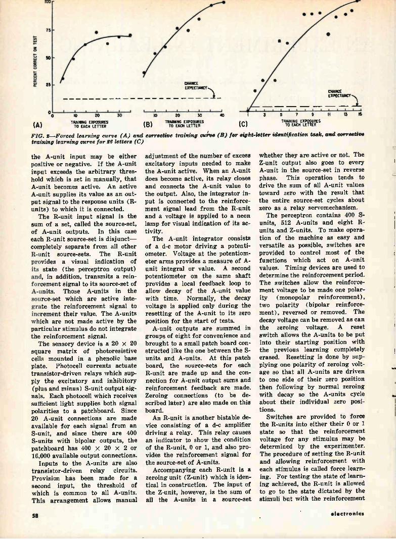
PERCENT CORRECT ON TEST
tdb
75
50
25
•
•
10 20
TRAINING EXPOSURES TO EACH LETTER
CHANCE EXPECTANCY
FIG. 2—Forced learning curve (A) and training learning curve for 26 letters (C)
the A-unit input may be either positive or negative. If the A-unit input exceeds the arbitrary thres-hold which is set in manually, that A-unit becomes active. An active A-unit supplies its value as an out-put signal to the response units (R-units) to which it is connected. The R-unit input signal is the
sum of a set, called the source-set, of A-unit outputs. In this case each R-unit source-set is disjunct— completely separate from all other R-unit source-sets. The R-unit provides a visual indication of its state (the perceptron output) and, in addition, transmits a rein-forcement signal to its source-set of A-units. Those A-units in the source-set which are active inte-grate the reinforcement signal to increment their value. The A-units which are not made active by the particular stimulus do not integrate the reinforcement signal. The sensory device is a 20 x 20
square matrix of photoresistive cells mounted in a phenolic base plate. Photocell currents actuate transistor-driven relays which sup-ply the excitatory and inhibitory (plus and minus) S-unit output sig-nals. Each photocell which receives sufficient light supplies both signal polarities to a patchboard. Since 20 A-unit connections are made available for each signal from an S-unit, and since there are 400 S-units with bipolar outputs, the patchboard has 400 x 20 x 2 or 16,000 available output connections.
Inputs to the A-units are also transistor-driven relay circuits. Provision has been made for a second input, the threshold of which is common to all A-units. This arrangement allows manual
(B)
lO 20 30
TRAINING EXPOSURES TO EACH LETTER
corrective
40
TRAINING EXPOSURES TO EACH LETTER C
CHANCE EXPECTANCY1
, I.
15
training curve (B) for eight-letter identification task, and corrective
adjustment of the number of excess excitatory inputs needed to make the A-unit active. When an A-unit does become active, its relay closes and connects the A-unit value to the output. Also, the integrator in-put is connected to the reinforce-ment signal lead from the R-unit and a voltage is applied to a neon lamp for visual indication of its ac-tivity. The A-unit integrator consists
of a d-c motor driving a potenti-ometer. Voltage at the potentiom-eter arms provides a measure of A-unit integral or value. A second potentiometer on the same shaft provides a local feedback loop to allow decay of the A-unit value with time. Normally, the decay voltage is applied only during the resetting of the A-unit to its zero position for the start of tests.
A-unit outputs are summed in groups of eight for convenience and brought to a small patch board con-structed like the one between the S-units and A-units. At this patch board, the source-sets for each R-unit are made up and the con-nection for A-unit output sums and reinforcement feedback are made. Zeroing connections (to be de-scribed later) are also made on this board. An R-unit is another bistable de-
vice consisting of a d-c amplifier driving a relay. This relay causes an indicator to show the condition of the R-unit, 0 or 1, and also pro-vides the reinforcement signal for the source-set of A-units. Accompanying each R-unit is a
zeroing unit (Z-unit) which is iden-tical in construction. The input of the Z-unit, however, is the sum of all the A-units in a source-set
whether they are active or not. The Z-unit output also goes to every A-unit in the source-set in reverse phase. This operation tends to drive the sum of all A-unit values toward zero with the result that the entire source-set cycles about zero as a relay servomechanism. The perceptron contains 400 S-
units, 512 A-units and eight R-units and Z-units. To make opera-tion of the machine as easy and versatile as possible, switches are provided to control most of the functions which act on A-unit values. Timing devices are used to determine the reinforcement period. The switches allow the reinforce-ment voltage to be made one polar-ity (monopolar reinforcement), two polarity (bipolar reinforce-ment), reversed or removed. The decay voltage can be removed as can the zeroing voltage. A reset switch allows the A-units to be put into their starting position with the previous learning completely erased. Resetting is done by sup-plying one polarity of zeroing volt-age so that all A-units are driven to one side of their zero position then following by normal zeroing with decay so the A-units cycle about their individual zero posi-tions.
Switches are provided to force the R-units into either their 0 or 1 state so that the reinforcement voltage for any stimulus may be determined by the experimenter. The procedure of setting the R-unit and allowing reinforcement with each stimulus is called force learn-ing. For testing the state of learn-ing achieved, the R-unit is allowed to go to the state dictated by the stimuli but with the reinforcement
r_-
98 electronics
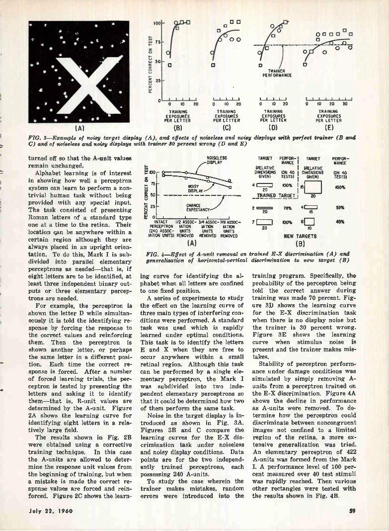
(A)
PERCENT CORRECT ON TEST
!00
75
50
25
O tii
0 10
TRAINING EXPOSURES PER LETTER
(B)
El 0 D
I. 11th
20 0 10 20
TRAINING EXPOSURES PER LETTER
(C)
TRAINER PERFORMANCE
0 10 20
TRAINING EXPOSURES PER LETTER
(D)
0 000 0
1 1 11111
O 10 20 30
TRAINING EXPOSURES PER LETTER
(E)
FIG. 3—Example of noisy target display (A), and effects of noiseless and noisy displays with perfect trainer (B and C) and of noiseless and noisy displays with trainer 30 percent wrong (D and E)
turned off so that the A-unit values remain unchanged.
Alphabet learning is of interest in showing how well a perceptron system can learn to perform a non-trivial human task without being provided with any special input. The task consisted of presenting Roman letters of a standard type one at a time to the retina. Their location c,an be anywhere within a certain region although they are always placed in an upright orien-tation. To do this, Mark I is sub-divided into parallel elementary perceptrons as needed—that is, if eight letters are to be identified, at least three independent binary out-puts or three elementary percep-trons are needed.
For example, the perceptron is shown the letter D while simultan-eously it is told the identifying re-sponse by forcing the response to the correct values and reinforcing them. Then the perceptron is shown another letter, or perhaps the same letter in a different posi-tion. Each time the correct re-sponse is forced. After a number of forced learning trials, the per-ceptron is tested by presenting the letters and asking it to identify them—that is, R-unit values are determined by the A-unit. Figure 2A shows the learning curve for identifying eight letters in a rela-tively large field. The results shown in Fig. 2B
were obtained using a corrective training technique. In this case the A-units are allowed to deter-mine the response unit values from the beginning of training, but when a mistake is made the correct re-sponse values are forced and rein-forced. Figure 2C shows the learn-
100
50
25
NOISELESS DISPLAY
NOISY DISPLAY
CHANCE EXPECTANCY
0 I INTACT 1/2 ASSOC- 3/4 ASSOC- 7/8 ASSOC-
PERCEPTRON 1ATION 1ATION IATION (240 ASSOC- UNITS UNITS UNITS IATION UNITS) REMOVED REMOVED REMOVED
(A)
TARGET PERFOR- TARGET MANCE
(RELATIVE DIMENSIONS (ON 40
GIVEN) TESTS)
4 1 100% 20
TRAINED TARGET
(RELATIVE DIMENSIONS
GIVEN)
15
20
PERFOR-MANCE
ION 40 TESTS)
100%
2 = 78% 93% 20 15
7 I 100% 8
20 10
NEW TARGETS
(B)
45%
FIG. 4—Effect of A-unit removal on trained E-X discrimination (A) and generalization of horizontal-vertical discrimination to new target (B)
ing curve for identifying the al-phabet when all letters are confined to one fixed position. A series of experiments to study
the effect on the learning curve of three main types of interfering con-ditions were performed. A standard task was used which is rapidly learned under optimal conditions. This task is to identify the letters E and X when they are free to occur anywhere within a small retinal region. Although this task can be performed by a single ele-mentary perceptron, the Mark I was subdivided into two inde-pendent elementary perceptrons so that it could be determined how two of them perform the same task.
Noise in the target display is in-troduced as shown in Fig. 3A. Figures 3B and C compare the learning curves for the E-X dis-crimination task under noiseless and noisy display conditions. Data points are for the two independ-ently trained perceptrons, each possessing 240 A-units. To study the case wherein the
trainer makes mistakes, random errors were introduced into the
training program. Specifically, the probability of the perceptron being told the correct answer during training was made 70 percent. Fig-ure 3D shows the learning curve for the E-X discrimination task when there is no display noise but the trainer is 30 percent wrong. Figure 3E shows the learning curve when stimulus noise is present and the trainer makes mis-takes.
Stability of perceptron perform-ance under damage conditions was simulated by simply removing A-units from a perceptron trained on the E-X discrimination. Figure 4A shows the decline in performance as A-units were removed. To de-termine how the perceptron could discriminate between noncongruent images not confined to a limited region of the retina, a more ex-tensive generalization was tried. An elementary perceptron of 422 A-units was formed from the Mark I. A performance level of 100 per-cent measured over 40 test stimuli was rapidly reached. Then various other rectangles were tested with the results shown in Fig. 4B.
July 22, 1960 59
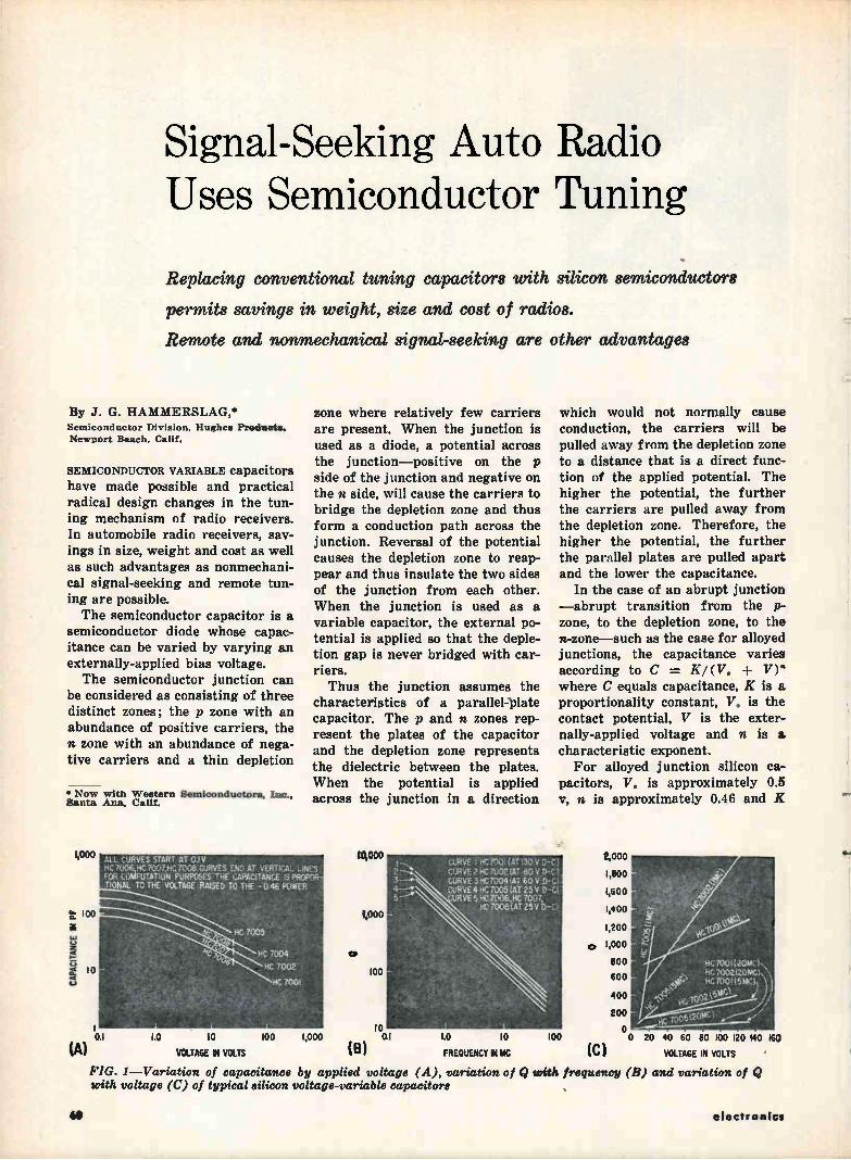
Signal-Seeking Auto Radio Uses Semiconductor Tuning
Replacing conventional tuning capacitors with silicon semiconductors
permits savings in weight, size and cost of radios.
Remote and nonmechanical signal-seeking are other advantages
By J. G. HAMMERSLAG,* Semiconductor Division, Hughes Products.
Newport Beach, Calif.
SEMICONDUCTOR VARIABLE capacitors have made possible and practical radical design changes in the tun-ing mechanism of radio receivers. In automobile radio receivers, sav-ings in size, weight and cost as well as such advantages as nonmechani-cal signal-seeking and remote tun-ing are possible. The semiconductor capacitor is a
semiconductor diode whose capac-itance can be varied by varying an externally-applied bias voltage. The semiconductor junction can
be considered as consisting of three distinct zones; the p zone with an abundance of positive carriers, the n zone with an abundance of nega-tive carriers and a thin depletion
• Now with Western Semiconductors, Inc., Santa Ana, Calif.
1,000
zone where relatively few carriers are present. When the junction is used as a diode, a potential across the junction—positive on the p side of the junction and negative on the n side, will cause the carriers to bridge the depletion zone and thus form a conduction path across the junction. Reversal of the potential causes the depletion zone to reap-pear and thus insulate the two sides of the junction from each other. When the junction is used as a variable capacitor, the external po-tential is applied so that the deple-tion gap is never bridged with car-riers. Thus the junction assumes the
characteristics of a parallel-plate capacitor. The p and n zones rep-resent the plates of the capacitor and the depletion zone represents the dielectric between the plates. When the potential is applied across the junction in a direction
ALL CURVES START AT 0.!V HC 7006 NC N.Y.27HC 7008 CURVES ENO. AT VERTWAL LINES' FUR COMFUTATIuN PURPOSES THE CAPACITANCE IS PROPNi• TIONAL To THE VOLTAGE RAISED TO THE - 046 POWER
RC 7005
HE 7004 )04.
HC 7002
RC 7001
0.1
(A)
1.0 10 100
VOLTAGE IN VOLTS
1,000
10,000
1,0 0 0
100
10 0.1
(B)
1.0 10
FREQUENCY IN I1C
which would not normally cause conduction, the carriers will be pulled away from the depletion zone to a distance that is a direct func-tion of the applied potential. The higher the potential, the further the carriers are pulled away from the depletion zone. Therefore, the higher the potential, the further the parallel plates are pulled apart and the lower the capacitance.
In the case of an abrupt junction —abrupt transition from the p-zone, to the depletion zone, to the n-zone—such as the case for alloyed junctions, the capacitance varies according to C = K/ (V. -F V)" where C equals capacitance, K is a proportionality constant, V. is the contact potential, V is the exter-nally-applied voltage and n is a characteristic exponent.
For alloyed junction silicon ca-pacitors, V. is approximately 0.5 y, n is approximately 0.46 and IZ
UCHIE I 110700 (er o-c CURVE 214C 702 1M 80 V D-C CURVE -3 4C7004 iAT 60 V O-c I CLIRVE 4 HE 7005 (AT 25V D-C; URVE 5 HE 7006,5E 7007
NE 7008(AT 25V
TOO
2,000
1,800
1,600
1,400
1,200
s, 1,000
800
600
400
200
o
(C)
NC 7001120M: I. NC 7002 iniel, \
4> HC300119,1,:l \ \ ) if
'
0 20 40 60 80 100 120
VOLTAGE IN VOLTS
FIG. 1—Variation of capacitance by applied voltage (A), variation of Q with frequency (B) and variation of Q with voltage (C) of typical silicon voltage-variable capacitors
160
60 electronics
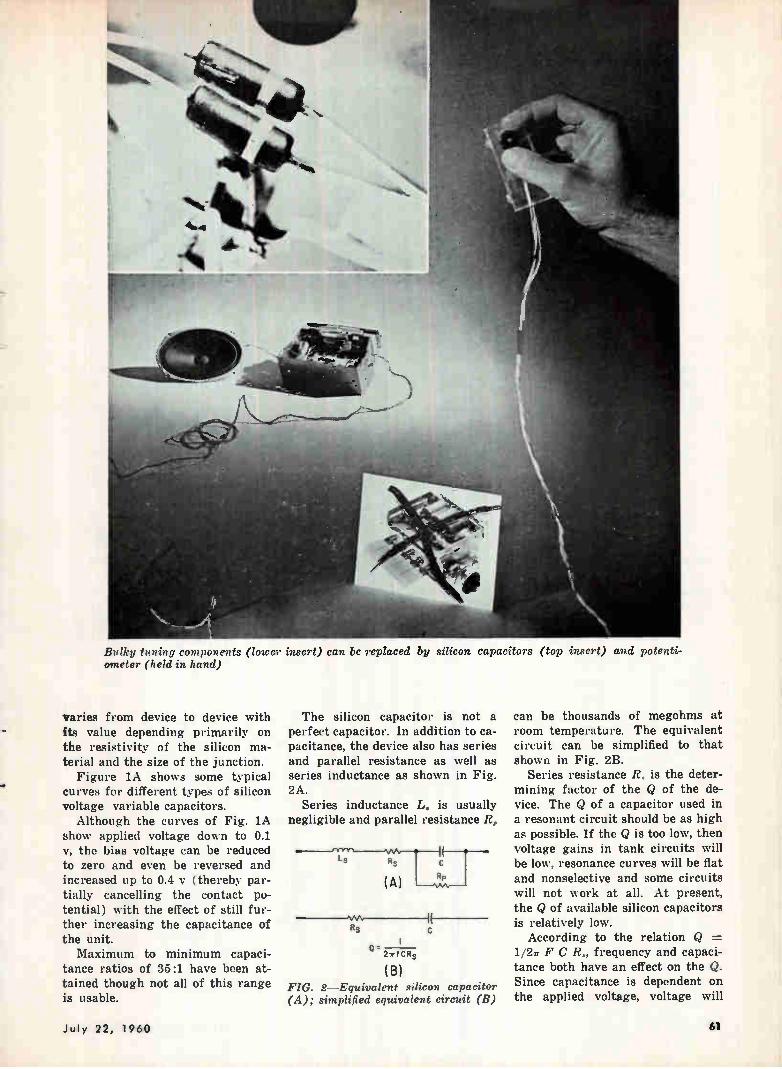
Bulky tuning components (lower insert) can be replaced by silicon capacitors (top insert) and potenti-ometer (held in hand)
varies from device to device with its value depending primarily on the resistivity of the silicon ma-terial and the size of the junction.
Figure lA shows some typical curves for different types of silicon voltage variable capacitors.
Although the curves of Fig. 1A show applied voltage down to 0.1 v, the bias voltage can be reduced to zero and even be reversed and increased up to 0.4 y (thereby par-tially cancelling the contact po-tential) with the effect of still fur-ther increasing the capacitance of the unit. Maximum to minimum capaci-
tance ratios of 35:1 have been at-tained though not all of this range is usable.
The silicon capacitor is not a perfect capacitor. In addition to ca-pacitance, the device also has series and parallel resistance as well as series inductance as shown in Fig. 2A.
Series inductance L. is usually negligible and parallel resistance R,
Ls
Rs
Rs
(A RP ) —Nna,—
Cr. 2rf CR s
(B)
It
FIG. 2—Equivalent silicon capacitor (A); simplified equivalent circuit (B)
can be thousands of megohms at room temperature. The equivalent circuit can be simplified to that shown in Fig. 2B.
Series resistance R. is the deter-mining factor of the Q of the de-vice. The Q of a capacitor used in a resonant circuit should be as high as possible. If the Q is too low, then voltage gains in tank circuits will be low, resonance curves will be flat and nonselective and some circuits will not work at all. At present, the Q of available silicon capacitors is relatively low.
According to the relation Q = 1/21r F C R„ frequency and capaci-tance both have an effect on the Q. Since capacitance is dependent on the applied voltage, voltage will
July 22, 1960 êl
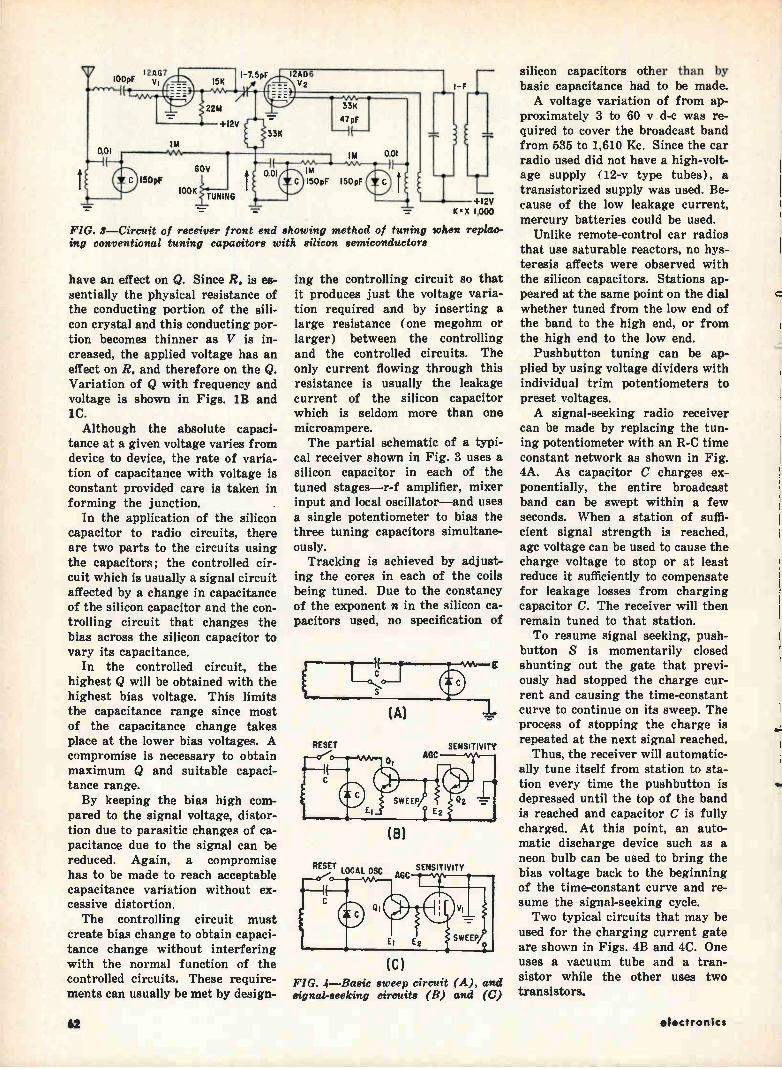
I2AG7 10OpF
100K TUNING
150pF 150pF
FIG. 3—Circuit of receiver front end showing method of tuning when replac-ing conventional tuning capacitors with silicon semiconductors
have an effect on Q. Since R. is es-sentially the physical resistance of the conducting portion of the sili-con crystal and this conducting por-tion becomes thinner as V is in-creased, the applied voltage has an effect on R. and therefore on the Q. Variation of Q with frequency and voltage is shown in Figs. 1B and 1C. Although the absolute capaci-
tance at a given voltage varies from device to device, the rate of varia-tion of capacitance with voltage is constant provided care is taken in forming the junction.
In the application of the silicon capacitor to radio circuits, there are two parts to the circuits using the capacitors; the controlled cir-cuit which is usually a signal circuit affected by a change in capacitance of the silicon capacitor and the con-trolling circuit that changes the bias across the silicon capacitor to vary its capacitance.
In the controlled circuit, the highest Q will be obtained with the highest bias voltage. This limits the capacitance range since most of the capacitance change takes place at the lower bias voltages. A compromise is necessary to obtain maximum Q and suitable capaci-tance range. By keeping the bias high com-
pared to the signal voltage, distor-tion due to parasitic changes of ca-pacitance due to the signal can be reduced. Again, a compromise has to be made to reach acceptable capacitance variation without ex-cessive distortion. The controlling circuit must
create bias change to obtain capaci-tance change without interfering with the normal function of the controlled circuits. These require-ments can usually be met by design-
SENSITIVITY
SENSITIVITY
ing the controlling circuit so that it produces just the voltage varia-tion required and by inserting a large resistance (one megohm or larger) between the controlling and the controlled circuits. The only current flowing through this resistance is usually the leakage current of the silicon capacitor which is seldom more than one microampere. The partial schematic of a typi-
cal receiver shown in Fig. 3 uses a silicon capacitor in each of the tuned stages—r-f amplifier, mixer input and local oscillator—and uses a single potentiometer to bias the three tuning capacitors simultane-ously.
Tracking is achieved by adjust-ing the cores in each of the coils being tuned. Due to the constancy of the exponent n in the silicon ca-pacitors used, no specification of
RESET
(B)
RESET LOCAL OSC AGC
E
(A)
(C) FIG. 4—Basic sweep circuit (A), and signal-seeking circuits (B) and (C)
silicon capacitors other than by basic capacitance had to be made. A voltage variation of from ap-
proximately 3 to 60 y d-c was re-quired to cover the broadcast band from 535 to 1,610 Kc. Since the car radio used did not have a high-volt-age supply (12-v type tubes), a transistorized supply was used. Be-
-cause of the low leakage current, mercury batteries could be used.
Unlike remote-control ear radios that use saturable reactors, no hys-teresis affects were observed with the silicon capacitors. Stations ap-peared at the same point on the dial whether tuned from the low end of the band to the high end, or from the high end to the low end.
Pushbutton tuning can be ap-plied by using voltage dividers with individual trim potentiometers to preset voltages. A signal-seeking radio receiver
can be made by replacing the tun-ing potentiometer with an R-C time constant network as shown in Fig. 4A. As capacitor C charges ex-ponentially, the entire broadcast band can be swept within a few seconds. When a station of suffi-cient signal strength is reached, age voltage can be used to cause the charge voltage to stop or at least reduce it sufficiently to compensate for leakage losses from charging capacitor C. The receiver will then remain tuned to that station. To resume signal seeking, push-
button S is momentarily closed shunting out the gate that previ-ously had stopped the charge cur-rent and causing the time-constant curve to continue on its sweep. The process of stopping the charge is repeated at the next signal reached.
Thus, the receiver will automatic-ally tune itself from station to sta-tion every time the pushbutton is depressed until the top of the band is reached and capacitor C is fully charged. At this point, an auto-matic discharge device such as a neon bulb can be used to bring the bias voltage back to the beginning of the time-constant curve and re-sume the signal-seeking cycle. Two typical circuits that may be
used for the charging current gate are shown in Figs. 4B and 4C. One uses a vacuum tube and a tran-sistor while the other uses two transistors.
62 electronics
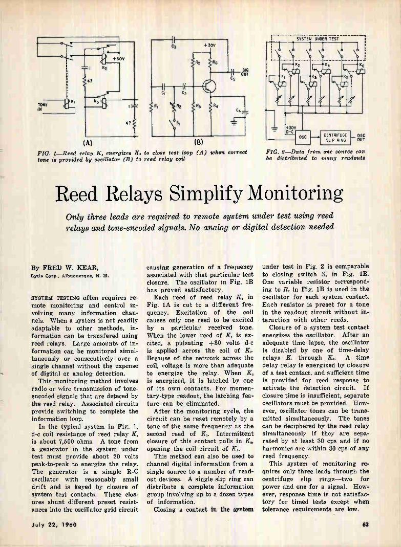
TONE IN
47
63
K2
+ 30V
47
(A) (B) FIG. 1—Reed relay K, energizes K, to close test loop (A) when correct tone is provided by oscillator (B) to reed relay coil
SYSTEM UNDER TEST
{Ji
64
CENTRIFUGE SLIP RING
OSC OUT
+30V D-C
OSC
FIG. 2—Data from one source can be distributed to many readouts
Reed Relays Simplify Monitoring Only three leads are required to remote system under test using reed
relays and tone-encoded signals. No analog or digital detection needed
By FRED W. KEAR, Lytle Corp., Albuquerque, N. M.
SYSTEM TESTING often requires re-mote monitoring and control in-volving many information chan-nels. When a system is not readily adaptable to other methods, in-formation can be transfered using reed relays. Large amounts of in-formation can be monitored simul-taneously or consecutively over a single channel without the expense of digital or analog detection.
This monitoring method involves radio or wire transmission of tone-encoded signals that are deteced by the reed relay. Associated circuits provide switching to complete the information loop.
In the typical system in Fig. 1, d-c coil resistance of reed relay K, is about 7,500 ohms. A tone from a generator in the system under test must provide about 20 volts peak-to-peak to energize the relay. The generator is a simple R-C oscillator with reasonably small drift and is keyed by closure of system test contacts. These clos-ures shunt different preset resist-ances into the oscillator grid circuit
causing generation of a frequency associated with that particular test closure. The oscillator in Fig. 1B has proved satisfactory. Each reed of reed relay K, in
Fig. lA is cut to a different fre-quency. Excitation of the coil causes only one reed to be excited by a particular received tone. When the lower reed of K, is ex-cited, a pulsating +30 volts d-c is applied across the coil of K.. Because of the network across the coil, voltage is more than adequate to energize the relay. When K2 is energized, it is latched by one of its own contacts. For momen-tary-type readout, the latching fea-ture can be eliminated.
After the monitoring cycle, the circuit can be reset remotely by a tone of the same frequency as the second reed of Ki. Intermittent closure of this contact pulls in opening the coil circuit of K2.
This method can also be used to channel digital information from a single source to a number of read-out devices. A single slip ring can distribute a complete information group involving up to a dozen types of information.
Closing a contact in the system-
under test in Fig. 2 is comparable to closing switch Si in Fig. 1B. One variable resistor correspond-ing to R. in Fig. 1B is used in the oscillator for each system contact. Each resistor is preset for a tone in the readout circuit without in-, teraction with other reeds.
Closure of a system test contact energizes the oscillator. After an adequate time lapse, the oscillator is disabled by one of time-delay relays K, through K.. A time delay relay is energized by closure of a test contact, and sufficient time is provided for reed response to activate the detection circuit. If closure time is insufficient, separate oscillators must be provided. How-ever, oscillator tones can be trans-mitted simultaneously. The tones can be deciphered by the reed relay simultaneously if they are sepa-rated by at least 30 cps and if no harmonics are within 30 cps of any reed frequency.
This system of monitoring re-quires only three leads through the centrifuge slip rings—two for power and one for a signal. How-ever, response time is not satisfac-tory for timed tests except when tolerance requirements are low.
July 22, 1960 63
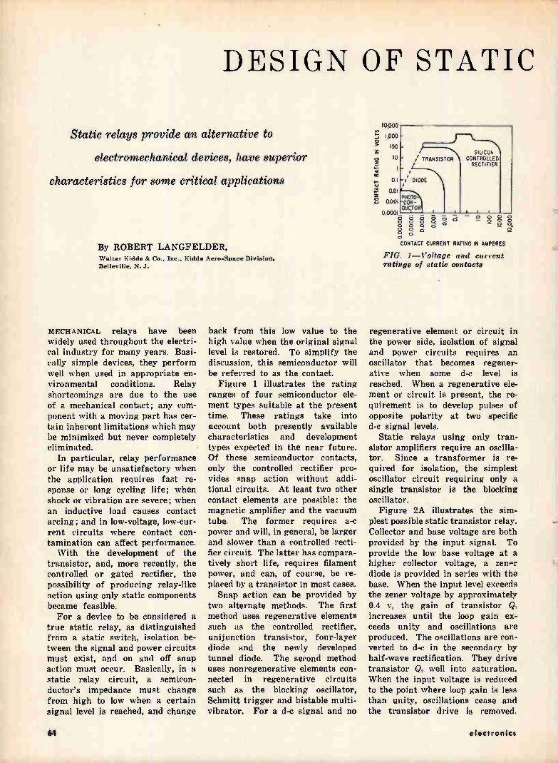
DESIGN OF STATIC
Static relays provide an alternative to
electromechanical devices, have superior
characteristics for some critical applications
By ROBERT LANGFELDER, Walter Kidde & Co., Inc.. Kidde Aero-Space Division. Belleville. N. .1.
MECHANICAL relays have been widely used throughout the electri-cal industry for many years. Basi-cally simple devices, they perform well when used in appropriate en-vironmental conditions. Relay shortcomings are due to the use of a mechanical contact; any com-ponent with a moving part has cer-tain inherent limitations which may be minimized but never completely eliminated.
In particular, relay performance or life may be unsatisfactory when the application requires fast re-sponse or long cycling life; when shock or vibration are severe; when an inductive load causes contact arcing; and in low-voltage, low-cur-rent circuits where contact con-tamination can affect performance. With the development of the
transistor, and, more recently, the controlled or gated rectifier, the possibility of producing relay-like action using only static components became feasible. For a device to be considered a
true static relay, as distinguished from a static switch, isolation be-tween the signal and power circuits must exist, and on and off snap action must occur. Basically, in a static relay circuit, a semicon-ductor's impedance must change from high to low when a certain signal level is reached, and change
back from this low value to the high value when the original signal level is restored. To simplify the discussion, this semiconductor will be referred to as the contact.
Figure 1 illustrates the rating ranges of four semiconductor ele-ment types suitable at the present time. These ratings take into account both presently available characteristics and development types expected in the near future. Of these semiconductor contacts, only the controlled rectifier pro-vides snap action without addi-tional circuits. At least two other contact elements are possible: the magnetic amplifier and the vacuum tube. The former requires a-c power and will, in general, be larger and slower than a controlled recti-fier circuit. The latter has compara-tively short life, requires filament power, and can, of course, be re-placed by a transistor in most cases.
Snap action can be provided by two alternate methods. The first method uses regenerative elements such as the controlled rectifier, uni junction transistor, four-layer diode and the newly developed tunnel diode. The second method uses nonregenerative elements con-nected in regenerative circuits such as the blocking oscillator, Schmitt trigger and bistable multi-vibrator. For a d-c signal and no
10,000
1,000
100
10
0.1
0.01
0.001
0.0001
TRANSISTOR
DIODE
PROT CON-DURTOR
SILICON CONTROLLED RECTIFIER
n
o 0 o o 8 ci ce ooez; o g o o o o CONTACT CURRENT RATING IN »PERES
FIG. 1—Voltage and current ratings of static contacts
§ §
regenerative element or circuit in the power side, isolation of signal and power circuits requires an oscillator that becomes regener-ative when some d-c level is reached. When a regenerative ele-ment or circuit is present, the re-quirement is to develop pulses of opposite polarity at two specific d-c signal levels.
Static relays using only tran-sistor amplifiers require an oscilla-tor. Since a transformer is re-quired for isolation, the simplest oscillator circuit requiring only a single transistor is the blocking oscillator.
Figure 2A illustrates the sim-plest possible static transistor relay. Collector and base voltage are both provided by the input signal. To provide the low base voltage at a higher collector voltage, a zener diode is provided in series with the base. When the input level exceeds the zener voltage by approximately 0.4 v, the gain of transistor CI increases until the loop gain ex-ceeds unity and oscillations are produced. The oscillations are con-verted to d-c in the secondary by half-wave rectification. They drive transistor Q. well into saturation. When the input voltage is reduced to the point where loop gain is less than unity, oscillations cease and the transistor drive is removed.
64 electronics
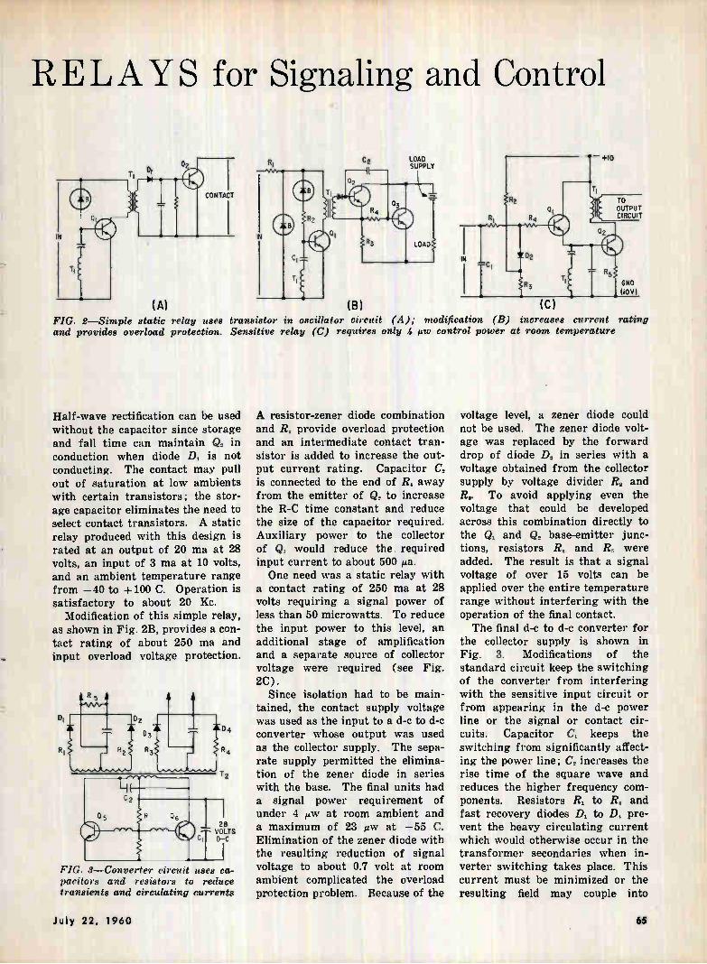
RELAYS for Signaling and Control
LOAD SUPPLY
TO OUTPUT CIRCUIT
(A) (B) (C)
FIG. 2—Simple static relay uses transistor in oscillator circuit (A); modification (B) increaees current rating and provides overload protection. Sensitive relay (C) requires only 4 uw control power at room temperature
Half-wave rectification can be used without the capacitor since storage and fall time can maintain Q, in conduction when diode D, is not conducting. The contact may pull out of saturation at low ambients with certain transistors; the stor-age capacitor eliminates the need to select contact transistors. A static relay produced with this design is rated at an output of 20 ma at 28 volts, an input of 3 ma at 10 volts, and an ambient temperature range from —40 to +100 C. Operation is satisfactory to about 20 Kc.
Modification of this simple relay, as shown in Fig. 2B, provides a con-tact rating of about 250 ma and input overload voltage protection.
FIG. 3—Converter circuit uses ca-pacitors and resistors to reduce transients and circulating currents
A resistor-zener diode combination and R, provide overload protection and an intermediate contact tran-sistor is added to increase the out-put current rating. Capacitor C2 is connected to the end of R, away from the emitter of Q, to increase the R-C time constant and reduce the size of the capacitor required. Auxiliary power to the collector of Q. would reduce the required input current to about 500 ¡La. One need was a static relay with
a contact rating of 250 ma at 28 volts requiring a signal power of less than 50 microwatts. To reduce the input power to this level, an additional stage of amplification and a separate source of collector voltage were required (see Fig. 2C).
Since isolation had to be main-tained, the contact supply voltage was used as the input to a d-c to d-c converter whose output was used as the collector supply. The sepa-rate supply permitted the elimina-tion of the zener diode in series with the base. The final units had a signal power requirement of under 4 w at room ambient and a maximum of 23 liw at —55 C. Elimination of the zener diode with the resulting reduction of signal voltage to about 0.7 volt at room ambient complicated the overload protection problem. Because of the
voltage level, a zener diode could not be used. The zener diode volt-age was replaced by the forward drop of diode D, in series with a voltage obtained from the collector supply by voltage divider R, and R.. To avoid applying even the voltage that could be developed across this combination directly to the Q. and Q, base-emitter junc-tions, resistors R. and 1?,, were added. The result is that a signal voltage of over 15 volts can be applied over the entire temperature range without interfering with the operation of the final contact. The final d-c to d-c converter for
the collector supply is shown in Fig. 3. Modifications of the standard circuit keep the switching of the converter from interfering with the sensitive input circuit or from appearing in the d-c power line or the signal or contact cir-cuits. Capacitor C, keeps the switching from significantly affect-ing the power line; C, increases the rise time of the square wave and reduces the higher frequency com-ponents. Resistors R, to R. and fast recovery diodes D. to D. pre-vent the heavy circulating current which would otherwise occur in the transformer secondaries when in-verter switching takes place. This current must be minimized or the resulting field may couple into
July 22, 1960 65
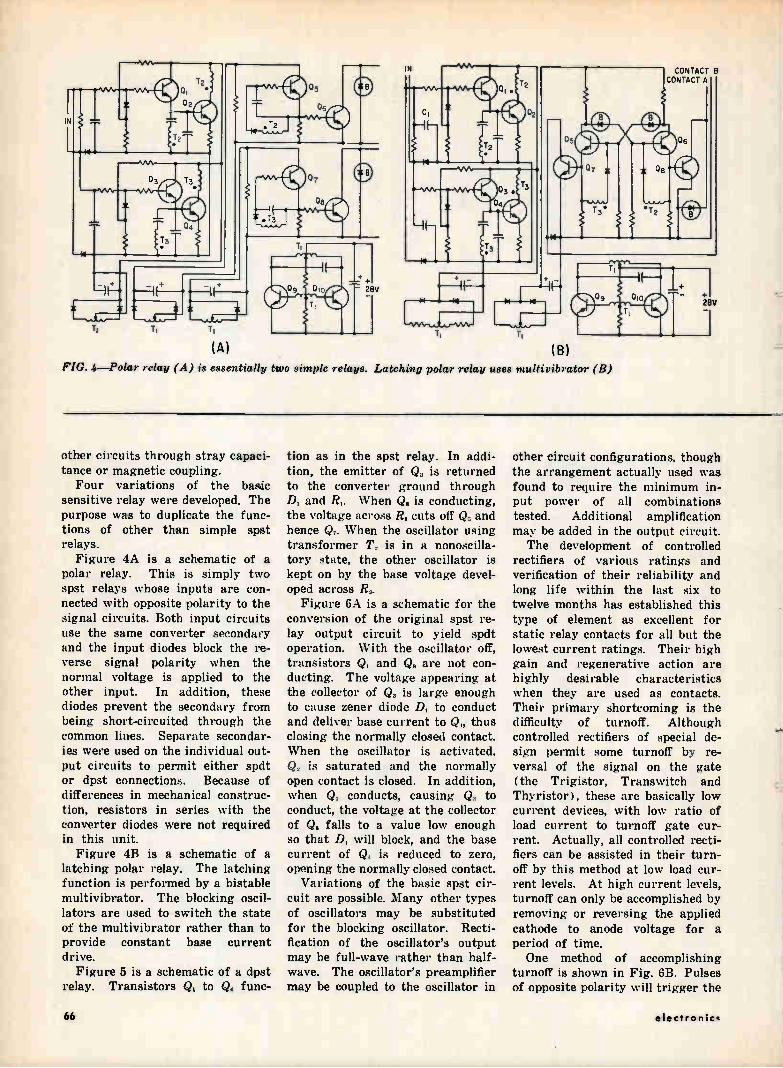
IN
(A) FIG. 4—Polar relay (A) is essentially two simple relays. Latching polar relay uses multivibrator (B)
CONTACT 8 CONTACT A
other circuits through stray capaci-tance or magnetic coupling. Four variations of the basic
sensitive relay were developed. The purpose was to duplicate the func-tions of other than simple spat relays.
Figure 4A is a schematic of a polar relay. This is simply two spst relays whose inputs are con-nected with opposite polarity to the signal circuits. Both input circuits use the same converter secondary and the input diodes block the re-verse signal polarity when the normal voltage is applied to the other input. In addition, these diodes prevent the secondary from being short-circuited through the common lines. Separate secondar-ies were used on the individual out-put circuits to permit either spdt or dpst connections. Because of differences in mechanical construc-tion, resistors in series with the converter diodes were not required in this unit. Figure 4B is a schematic of a
latching polar relay. The latching function is performed by a bistable multivibrator. The blocking oscil-lators are used to switch the state of the multivibrator rather than to provide constant base current drive.
Figure 5 is a schematic of a dpst relay. Transistors Q, to Q, func-
tion as in the spst relay. In addi-tion, the emitter of Q. is returned to the converter ground through D, and R,. When Q. is conducting, the voltage across R, cuts off Q„ and hence Q. When the oscillator using transformer T. is in a nonoscilla-tory state, the other oscillator is kept on by the base voltage devel-oped across R..
Figure 6A is a schematic for the conversion of the original spst re-lay output circuit to yield spdt operation. With the oscillator off, transistors Q, and Q. are not con-ducting. The voltage appearing at the collector of Q,, is large enough to cause zener diode D, to conduct and deliver base current to Q,, thus closing the normally closed contact. When the oscillator is activated, Q. is saturated and the normally open contact is closed. In addition, when Q, conducts, causing Q. to conduct, the voltage at the collector of Q. falls to a value low enough so that D, will block, and the base current of Q, is reduced to zero, opening the normally closed contact.
Variations of the basic spst cir-cuit are possible. Many other types of oscillators may be substituted for the blocking oscillator. Recti-fication of the oscillator's output may be full-wave rather than half-wave. The oscillator's preamplifier may be coupled to the oscillator in
other circuit configurations, though the arrangement actually used was found to require the minimum in-put power of all combinations tested. Additional amplification may be added in the output circuit. The development of controlled
rectifiers of various ratings and verification of their reliability and long life within the last six to twelve months has established this type of element as excellent for static relay contacts for all but the lowest current ratings. Their high gain and regenerative action are highly desirable characteristics when they are used as contacts. Their primary shortcoming is the difficulty of turnoff. Although controlled rectifiers of special de-sign permit some turnoff by re-versal of the signal on the gate (the Trigistor, Transwitch and Thyristor), these are basically low current devices, with low ratio of load current to turnoff gate cur-rent. Actually, all controlled recti-fiers can be assisted in their turn-off by this method at low load cur-rent levels. At high current levels, turnoff can only be accomplished by removing or reversing the applied cathode to anode voltage for a period of time. One method of accomplishing
turnoff is shown in Fig. 6B. Pulses of opposite polarity will trigger the
66 electron ict
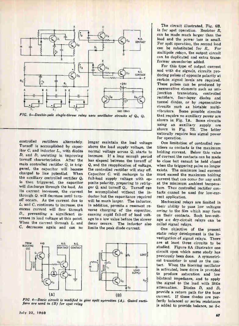
Ti T T GND (28V)
FIG. 5—Double-pole single-throw relay uses oscillator circuits of Q., Q.
N.O. CONTACT
controlled rectifiers alternately. Turnoff is accomplished by capac-itor C, and inductor Li, with diodes D, and D, assisting in improving turnoff characteristics. After the main controlled rectifier Q, is trig-gered, the capacitor will become charged to line potential. When the auxiliary controlled rectifier Q, is then triggered, the capacitor will discharge through the load. As its current increases, the current through Q, will decrease until turn-off occurs. As the current due to L, and C, continues to increase, the excess current will flow through D„ preventing a significant in-crease in load voltage at this point. When the current through L, and C, decreases again and can no
FROM BLOCKING
OSC
+10
longer maintain the load voltage above the load supply voltage, the normal voltage across Q, starts to increase. If a long enough period has elapsed between the turnoff of Qi and the reapplication of voltage, the controlled rectifier will stay off. Capacitor C, will recharge to the full-load supply voltage with op-posite polarity, preparing to retrig-ger Q, and turnoff Q2. Turnoff can be accomplished without the in-ductor but the capacitance required will be much larger. The inductor, in addition, permits a resonant re-verse charging of the capacitor, causing rapid fall-off of load volt-age to a low value before the slower decay occurs. The inductor also limits the peak diode current.
(A) (B)
FIG. 6—Basic circuit is modified to give spdt operation (A). Gated recti-fiers are used in (B) for ape relay
The circuit illustrated, Fig. 6B, is for spst operation. Resistor R, can be made much larger than the load and the power loss is small. For spdt operation, the second load can be substituted for R2. For multipole relays, the output circuit can be duplicated and extra trans-. former secondaries added. For this type of output current
and with d-e signals, circuits pro-ducing pulses of opposite polarity at certain signal levels are required. These pulses can be produced by regenerative elements such as uni-junction transistors, controlled rectifiers, four-layer diodes and tunnel diodes, or by regenerative circuits such as bistable multi-vibrators. Some possible circuits that require no auxiliary power are shown in Fig. 7A. Some circuits using an auxiliary supply are shown in Fig. 7B. The latter naturally require less signal power for operation.
One limitation of controlled rec-tifiers as contacts is the maximum holding current. Below this value of current the contacts can be made to close but cannot be held closed when the triggering pulse no longer exists. The minimum load current must exceed the maximum holding current that can occur for any unit at the minimum ambient tempera-ture. Thus controlled rectifier con-tacts cannot be used for low-cur-rent application.
Mechanical relays are limited in their ability to pass low voltages owing to the film which may form on their contacts. Such low-volt-age a-c dry-circuit relays can be called signal relays. One objective of the present
static relay development is the in-vestigation of signal relays. There are at least three circuits to be studied. Figure 8A illustrates one circuit upon which some study has previously been done. A symmetri-cal transistor is used as the con-tact. When the blocking oscillator is activated, base drive is provided to produce saturation and low bilateral impedance, and to apply the signal to the load with little attenuation. Diodes Di and Dt
provide a return path for the base current. If these diodes are per-fectly balanced or series resistance is added to provide balance, no d-c
July 22, 1960 61
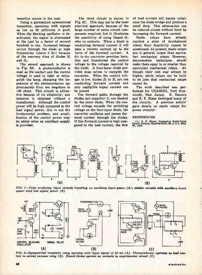
insertion occurs in the load. Using a germanium symmetrical
transistor, operation with signals as low as 50 millivolts is good. When the blocking oscillator is de-activated, the signal is attenuated at the load by a factor of several hundred to one. Increased leakage occurs through the diode at high frequencies (above 5 Kc ) because of the recovery time of diodes Di and D,. The second approach is shown
in Fig. 8B. A photoconductor is used as the contact and the control voltage is used to light or extin-guish the lamp, changing the im-pedance of the photoconductor ap-proximately from ten megohms to 100 ohms. This circuit is attrac-tive because of its simplicity; and isolation is obtained without a transformer. Although the control' power will be high compared to the load signal power, this is not the fundamental problem, and ampli-fication of the control power may be added when an auxiliary supply is provided.
(A)
The third circuit is shown in Fig. 8C. This may not be the most practical approach, because of the large number of extra circuit com-ponents required, but it illustrates the possibility of using biased di-odes as contacts. When a diode is conducting forward current it will pass a reverse current up to the value of the forward current. A d-c to d-e converter provides isola-tion and transforms the control voltage to the voltage required by the diode. A four-layer diode pro-vides snap action to energize the converter. When the control volt-age is low, diodes D, to D, are not conducting forward current and only negligible signal current can be passed. The forward paths through the
diodes and capacitor C, are blocked by the zener diode. When the con-trol voltage exceeds the switching voltage on the four-layer diode, the converter oscillates and passes for-ward current through the diodes. If this forward current is high com-pared to the load current, the flow
SCR'
4
rIEÉ1
of load current will barely unbal-ance the diode bridge and produce a small drop. This attenuation can be reduced almost without limit by increasing the forward current.
Static relays have already reached a state of development where their feasibility cannot be questioned. At present, static relays are in general, larger than equiva-lent mechanical relays. However, micromodule techniques should make them equal to or smaller than equivalent mechanical relays. Al-though their cost may always be higher, static relays can be built to do jobs that mechanical relays cannot do. The work described was per-
formed for USASRDL, Fort Mon-mouth, New Jersey. E. Demers and R. F. Blake developed many of the circuits. A previous article' gave details on static relays for power circuits'.
REFERENCES (1) R. F. Blake, Designing Solid-State
Power Relays, ELscraoxics, 33, p 114, May 27, 1960.
2
(B)
FOUR LAYER DIODE
FIG. 7—Pulse producing input circuits requiring no auxiliary input power (A); similar circuits with auxiliary input power need less signal power (B)
+10
ACTUA-TION INPUT
CONTROL BLOCKING SIGNAL RELAY OSCILLATOR
(A)
PHOTOCONDUCTOR
SIGNAL VOLTAGE LOAD
CONTROL VOLTAGE
(B) (C) FIG. 8—Symmetrical transistor relay operates with input signal of 50 Inv (A). Photoconductor operates tact in special purpose relay (B). Biased diodes operate as contacts in experimental circuit (C)
68
as load con-
electronics
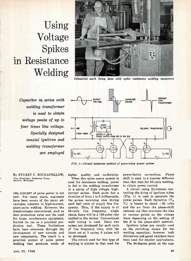
Using Voltage Spikes
in Resistance Welding
Capacitor in series with
welding transformer
is used to obtain
voltage peaks of up to
four times line voltage.
Specially designed
coaxial ignitron and
welding transformer
are employed
By STUART C. ROCKAFELLOW, Vice President. Robotron Corp.. Detroit, Michigan
THE CONCEPT of pulse power is not new. For many years, engineers have been aware of the many ad-vantages inherent in high-current, short-pulse welding. However, the disadvantages encountered, such as slow production rates and the need for large, cumbersome equipment, limited its use as a practical pro-duction tool. These limitations have been overcome through the development of new circuits and new components. The result is a practical system of pulse power welding that produces welds of
Industrial work being done with spike resistance welding equipment
SUPPLY VOLTAGE
CAPACITOR CHARGE
CURRENT THRU TRANSFORMER
A-C LINE
FROM TIMER SER ES R LIMITS PHASE SHIFTS FROM 90 TO 180 DEG
V
T2-SEC
-II+
WELDING TRANSFORMER
V3
FIG. 1—Circuit indicates method of generating power pulses
higher quality and uniformity. When this spike power system is
used for resistance welding, power is fed to the welding transformer in a series of high voltage, high-current pulses. Each pulse has a duration of from 1 to 3 milliseconds, the pulses occurring once during each half cycle of supply line fre-quency. Thus, if the supply is at 60-cycle line frequency, single phase, there will be a 120-pulse rate applied to the welder. Conventional weld timing is used. Since two pulses are developed for each cycle of line frequency time, with the timer set at 3 cycles, 6 pulses will be developed. The circuit used for this type of
welding is similar to that used for
T,_sEc ji f
power-factor corrections. Phase shift is used, in a manner different than that used for 60-cycle welding, to obtain power control. A circuit using thyratrons con-
trolling the firing of ignitron tubes (Fig. 1) is used to generate the power pulses. Each thyratron (V. 174) is biased to about —50 volts and the a-c from the phase-shift network can then overcome the bias at various points on the voltage wave depending on the setting of the R in the phase-shift network.
Ignitron tubes are usually used as the switching means for the welding operation; however, both thyratrons and gated rectifiers have been used for smaller applications. The 90-degree point on the sup-
July 22, 1960 69
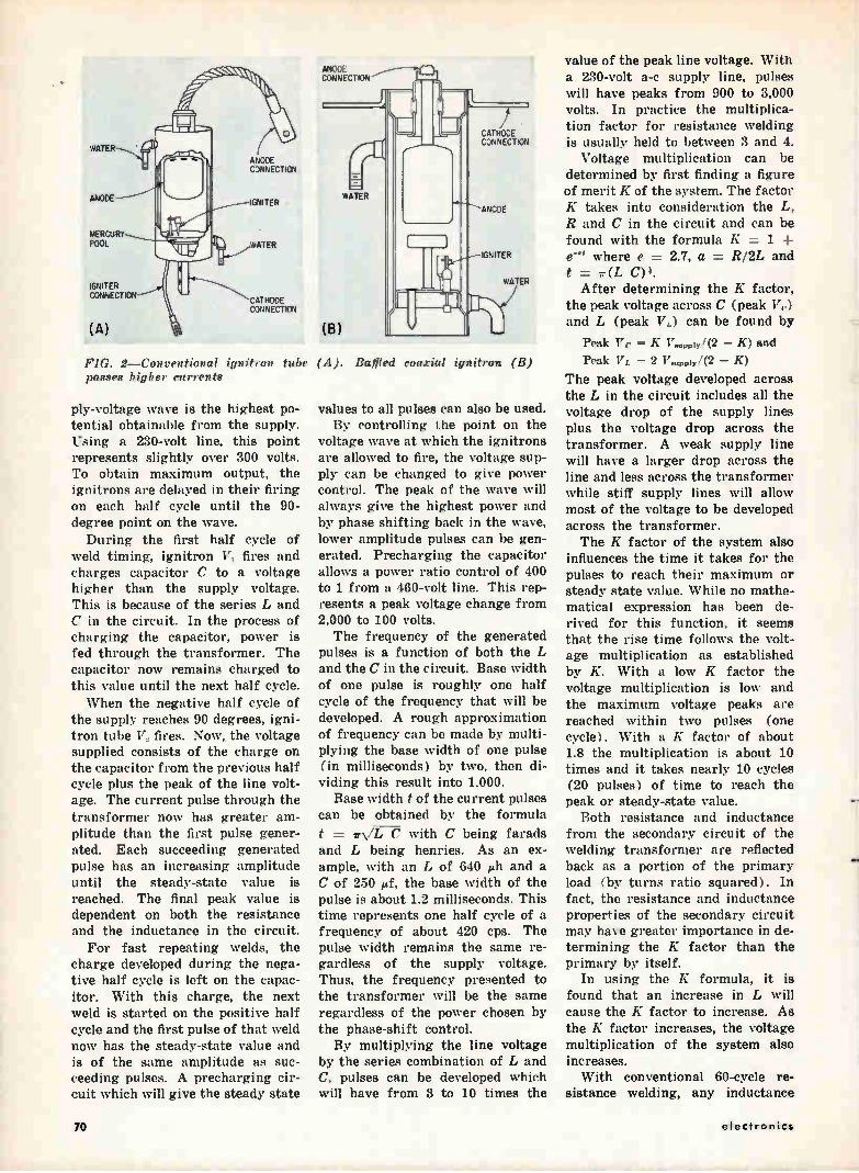
WATER
ANODE
MERCURY POOL
IGNITER CONNECTION
(A)
ANODE CONNECTION
IGNITER
WATER
CATHODE CONNECTION
ANODE CONNECTION
(B)
WATER
CATHODE CONNECTION
ANODE
IGNITER
WATER
FIG. 2—Conventional ignitron tube (A). Baffled coaxial ignitron (B) passes higher currents
ply-voltage wave is the highest po-tential obtainable from the supply. Using a 230-volt line, this point represents slightly over 300 volts. To obtain maximum output, the ignitrons are delayed in their firing on each half cycle until the 90-degree point on the wave. During the first half cycle of
weld timing, ignitron V, fires and charges capacitor C to a voltage higher than the supply voltage. This is because of the series L and C in the circuit. In the process of charging the capacitor, power is fed through the transformer. The capacitor now remains charged to this value until the next half cycle. When the negative half cycle of
the supply reaches 90 degrees, igni-tron tube 172 fires. Now, the voltage supplied consists of the charge on the capacitor from the previous half cycle plus the peak of the line volt-age. The current pulse through the transformer now has greater am-plitude than the first pulse gener-ated. Each succeeding generated pulse has an increasing amplitude until the steady-state value is reached. The final peak value is dependent on both the resistance and the inductance in the circuit.
For fast repeating welds, the charge developed during the nega-tive half cycle is left on the capac-itor. With this charge, the next weld is started on the positive half cycle and the first pulse of that weld now has the steady-state value and is of the same amplitude as suc-ceeding pulses. A precharging cir-cuit which will give the steady state
values to all pulses can also be used. By controlling the point on the
voltage wave at which the ignitrons are allowed to fire, the voltage sup-ply can be changed to give power control. The peak of the wave will always give the highest power and by phase shifting back in the wave, lower amplitude pulses can be gen-erated. Precharging the capacitor allows a power ratio control of 400 to 1 from a 460-volt line. This rep-resents a peak voltage change from 2,000 to 100 volts. The frequency of the generated
pulses is a function of both the L and the C in the circuit. Base width of one pulse is roughly one half cycle of the frequency that will be developed. A rough approximation of frequency can be made by multi-plying the base width of one pulse (in milliseconds) by two, then di-viding this result into 1,000.
Base width t of the current pulses can be obtained by the formula
t = irN/L C with C being farads and L being henries. As an ex-ample, with an L of 640 eh and a C of 250 ¡if, the base width of the pulse is about 1.2 milliseconds. This time represents one half cycle of a frequency of about 420 cps. The pulse width remains the same re-gardless of the supply voltage. Thus, the frequency presented to the transformer will be the same regardless of the power chosen by the phase-shift control. By multiplying the line voltage
by the series combination of L and C, pulses can be developed which will have from 3 to 10 times the
value of the peak line voltage. With a 230-volt a-c supply line, pulses will have peaks from 900 to 3,000 volts. In practice the multiplica-tion factor for resistance welding is usually held to between 3 and 4.
Voltage multiplication can be determined by first finding a figure of merit K of the system. The factor K takes into consideration the L, R and C in the circuit and can be found with the formula K = 1 ±
where e = 2.7, a = R/2L and t = ir(L C).
After determining the K factor, the peak voltage across C (peak V r) and L (peak VL) can be found by
Peak Ve = K V 111(2 — K) and
Peak VL = 2 V•upply/(2 K)
The peak voltage developed across the L in the circuit includes all the voltage drop of the supply lines plus the voltage drop across the transformer. A weak supply line will have a larger drop across the line and less across the transformer while stiff supply lines will allow most of the voltage to be developed across the transformer. The K factor of the system also
influences the time it takes for the pulses to reach their maximum or steady state value. While no mathe-matical expression has been de-rived for this function, it seems that the rise time follows the volt-age multiplication as established by K. With a low K factor the voltage multiplication is low and the maximum voltage peaks are reached within two pulses (one cycle). With a K factor of about 1.8 the multiplication is about 10 times and it takes nearly 10 cycles (20 pulses) of time to reach the peak or steady-state value.
Both resistance and inductance from the secondary circuit of the welding transformer are reflected back as a portion of the primary load (by turns ratio squared). In fact, the resistance and inductance properties of the secondary circuit may have greater importance in de-termining the K factor than the primary by itself.
In using the K formula, it is found that an increase in L will cause the K factor to increase. As the K factor increases, the voltage multiplication of the system also increases. With conventional 60-cycle re-
sistance welding, any inductance
711 electronics
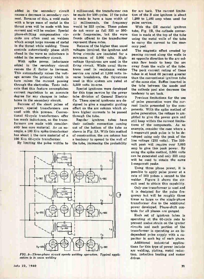
added in the secondary circuit causes a decrease in secondary cur-rent. Because of this, a weld made with a large mass of metal in the throat area will be made with less current and will be weaker. Special phase-shifting compensation cir-cuits are often used on welders which accept large masses of metal in the throat while welding. These controls automatically phase shift ahead in the wave as inductance is added in the secondary circuit. With spike power, inductance
added in the secondary circuit causes the K factor to increase. This automatically raises the volt-age across the primary which in turn raises the current passing through the electrodes. Tests indi-cate that this feature accomplishes current regulation to an accurate degree for any changes in induc-tance in the secondary circuit.
Because of the short pulses of power, special transformers are used with this process. Conven-tional 60-cycle transformers offer too much inductance, so the trans-formers are made with consider-ably less core material. As an ex-ample, a 100 Kva spike transformer has about à the core material of a 100 Kva 60-cycle transformer. By limiting the pulse widths to
FIG. 8—Three-phase circuit speeds uelding operation. Typical appli-cation is in seam welding
1 millisecond, the transformer can be made for 500 cycles. If the pulse is made to have a base width of 1 milliseconds, the frequency would be 333 cycles. These pulses do not occur as full 333 or 500-cycle frequencies, but the wave fronts offered to the transformer represent these rates.
Because of the higher than usual voltages involved, the ignitron and firing circuits are insulated for a minimum of 5,000 volts. High-voltage thyratrons are used in the firing circuit. While usual thyra-trons used in resistance welder service are rated at 1,500 volts in-verse breakdown, the thyratrons used in this system are rated at 3,500 volts inverse.
Special ignitrons were developed for this type service by the power tube division of General Electric Co. These special ignitrons are de-signed to give a magnetic guiding effect on the arc column which al-lows higher currents to be passed through the tube.
Regular ignitron tubes have their cathode connection coming out of the bottom of the tube as shown in Fig. 2A. With this method of construction, the arc column has a tendency to spread to the wall of the tube, increasing the probability
for arc back. The current limita-tion of the B size ignitron is about 1,200 to 1,400 amp when used for pulse service.
With the GE coaxial ignitron tube, Fig. 2B, the cathode connec-tion is made at the top of the tube using the metal walls of the tube to carry the current to the mer-cury pool.
The magnetic effect created by passing current along the walls in an opposite direction to the arc col-umn flow tends to keep the arc away from the walls of the tube. The peak current rating of these tubes is at least 60 percent greater than the conventional ignitron tube of the same size. Baffles inserted in the tube between the anode and the cathode pool also decrease the tendency to arc back.
Previous limitations for the use of pulse generation were the cur-rent limits presented by the com-ponents. With the spike method of pulse generation, the voltage is am-plified to give the power gain and still keep within the current limita-tions of the components. As an example, consider the case where a 1-megawatt peak pulse is to be de-veloped using only the peak of the line voltage (230 volts). The 300-volt peak will require over 3,000 amp to give this peak power. By using the spike method, 3,000 volts can be generated and only 333 amp will be used to obtain the same 1-megawatt peaks. Using three phase power, it is
possible to apply pulse power at a rate of 360 pulses a second to the welder. Figure 3 shows the cir-cuit used to obtain this capability.
Only one transformer is used and it is designed for the pulse fre-quency but will be roughly three times as large as the single-phase transformer due to the additional power developed. Phase-shift con-trols for all phases are ganged. Each set of ignitron tubes is
operating at the 60-cycle rate to prevent undue strain on the ignitor circuits and each portion of the transformer is operating as an in-dependent pulse supply with a ca-pacitor in each leg of each phase.
Additional industrial applica-tions for this type of power include arc welding, plating, metal reduc-tion, induction heating and motor drives.
July 22, 1960 71
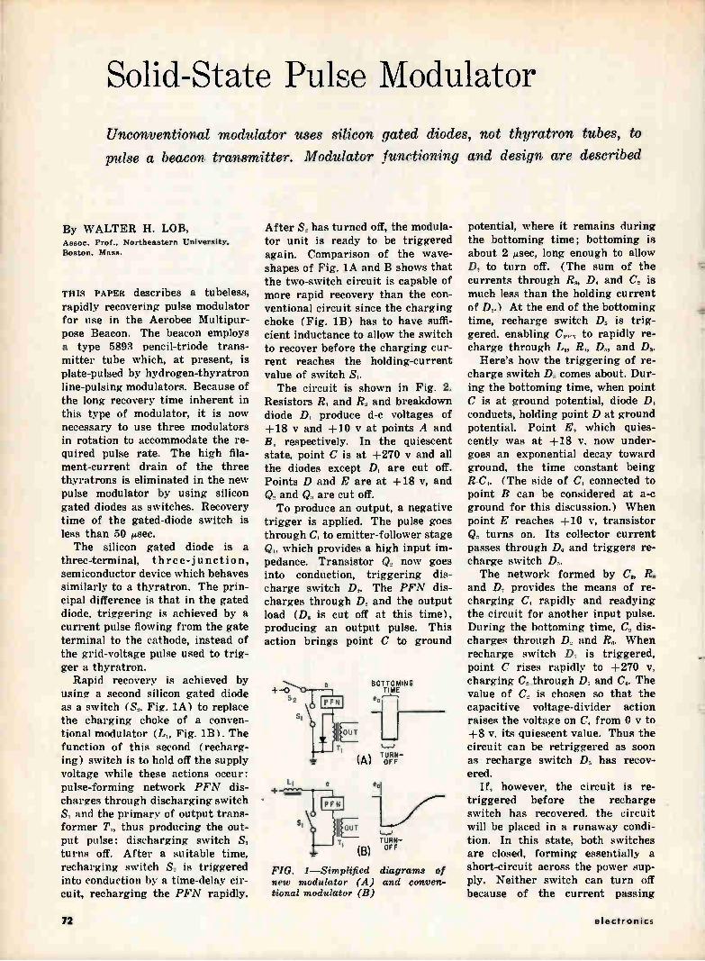
Solid-State Pulse Modulator
Unconventional modulator uses silicon gated diodes, not thyratron tubes, to
pulse a beacon transmitter. Modulator functioning and design are described
By WALTER H. LOB, Assoc. Prof.. Northeastern University. Boston, Mass.
THIS PAPER describes a tubeless, rapidly recovering pulse modulator for use in the Aerobee Multipur-pose Beacon. The beacon employs a type 5892 pencil-triode trans-mitter tube which, at present, is plate-pulsed by hydrogen-thyratron line-pulsing modulators. Because of the long recovery time inherent in this type of modulator, it is now necessary to use three modulators in rotation to accommodate the re-quired pulse rate. The high fila-ment-current drain of the three thyratrons is eliminated in the new pulse modulator by using silicon gated diodes as switches. Recovery time of the gated-diode switch is less than 50 µsec. The silicon gated diode is a
three-terminal, three-junction, semiconductor device which behaves similarly to a thyratron. The prin-cipal difference is that in the gated diode, triggering is achieved by a current pulse flowing from the gate terminal to the cathode, instead of the grid-voltage pulse used to trig-ger a thyratron.
Rapid recovery is achieved by using a second silicon gated diode as a switch (S„ Fig. 1A) to replace the charging choke of a conven-tional modulator (L„ Fig. 1B). The function of this second (recharg-ing) switch is to hold off the supply voltage while these actions occur: pulse-forming network PFN dis-charges through discharging switch • S, and the primary of output trans-former T„ thus producing the out-put pulse; discharging switch SI turns off. After a suitable time, recharging switch S, is triggered into conduction by a time-delay cir-cuit, recharging the PFN rapidly.
After S. has turned off, the modula-tor unit is ready to be triggered again. Comparison of the wave-shapes of Fig. 1A and B shows that the two-switch circuit is capable of more rapid recovery than the con-ventional circuit since the charging choke (Fig. 1B) has to have suffi-cient inductance to allow the switch to recover before the charging cur-rent reaches the holding-current value of switch S,. The circuit is shown in Fig. 2.
Resistors R, and R, and breakdown diode D, produce d-c voltages of +18 y and +10 I/ at points A and B, respectively. In the quiescent state, point C is at +270 y and all the diodes except D, are cut off. Points D and E are at +18 v, and Q. and Q. are cut off. To produce an output, a negative
trigger is applied. The pulse goes through C, to emitter-follower stage Q,. which provides a high input im-pedance. Transistor Q, now goes into conduction, triggering dis-charge switch D,. The PFN dis-charges through D, and the output load (D, is cut off at this time), producing an output pulse. This action brings point C to ground
(A)
BOTTOMING TIME
••••
LJ TURN-OFF
eal
TURN— OFF
FIG. 1—Simplified diagrams of new modulator (A) and conven-tional modulator (B)
potential, where it remains during the bottoming time; bottoming is about 2 µsec, long enough to allow D, to turn off. (The sum of the currents through R„ D, and C. is much less than the holding current of D..) At the end of the bottoming time, recharge switch D. is trig-gered, enabling Cp., to rapidly re-charge through L„ R., D., and D..
Here's how the triggering of re-charge switch D. comes about. Dur-ing the bottoming time, when point C is at ground potential, diode D. conducts, holding point D at ground potential. Point E, which quies-cently was at +18 v. now under-goes an exponential decay toward ground, the time constant being R C,. (The side of C. connected to point B can be considered at a-c ground for this discussion.) When point E reaches +10 v, transistor Q. turns on. Its collector current passes through D. and triggers re-charge switch D.. The network formed by C,, R.
and D, provides the means of re-charging C, rapidly and readying the circuit for another input pulse. During the bottoming time, C, dis-charges through D, and R.. When recharge switch D. is triggered, point C rises rapidly to +270 v, charging C,_through D, and C.. The value of C, is chosen so that the capacitive voltage-divider action raises the voltage on C, from 0 y to +8 v, its quiescent value. Thus the circuit can be retriggered as soon as recharge switch D. has recov-ered.
If, however, the circuit is re-triggered before the recharge switch has recovered, the circuit will be placed in a runaway condi-tion. In this state, both switches are closed, forming essentially a short-circuit across the power sup-ply. Neither switch can turn off because of the current passing
72 electronics
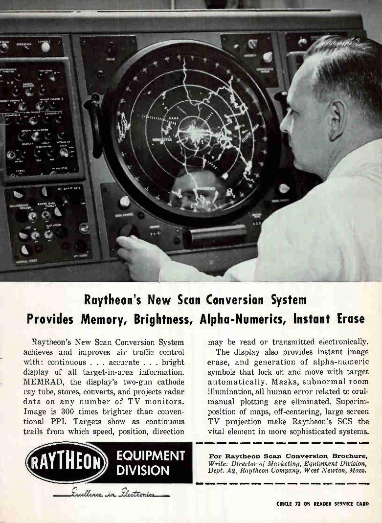
Raytheon's New Scan Conversion System
Provides Memory, Brightness, Alpha-Numerics, Instant Erase
Raytheon's New Scan Conversion System achieves and improves air traffic control with: continuous . . . accurate . . . bright display of all target-in-area information. MEMRAD, the display's two-gun cathode ray tube, stores, converts, and projects radar data on any number of TV monitors. Image is 300 times brighter than conven-tional PPI. Targets show as continuous trails from which speed, position, direction
RAYTHEON EQUIPMENT DIVISION
may be read or transmitted electronically. The display also provides instant image
erase, and generation of alpha-numeric symbols that lock on and move with target automatically. Masks, subnormal room illumination, all human error related to oral-manual plotting are eliminated. Superim-position of maps, off-centering, large screen TV projection make Raytheon's SCS the vital element in more sophisticated systems.
For Raytheon Scan Conversion Brochure,
Write: Director of Marketing, Equipment Division, Dept. A2, Raytheon Company, West Newton, Mass.
OM» MOM WM« IMMIIIM «Niel
.--gxcdiencc. —eecfrwnica—. CIRCLE 13 ON READER SPOKE CARD
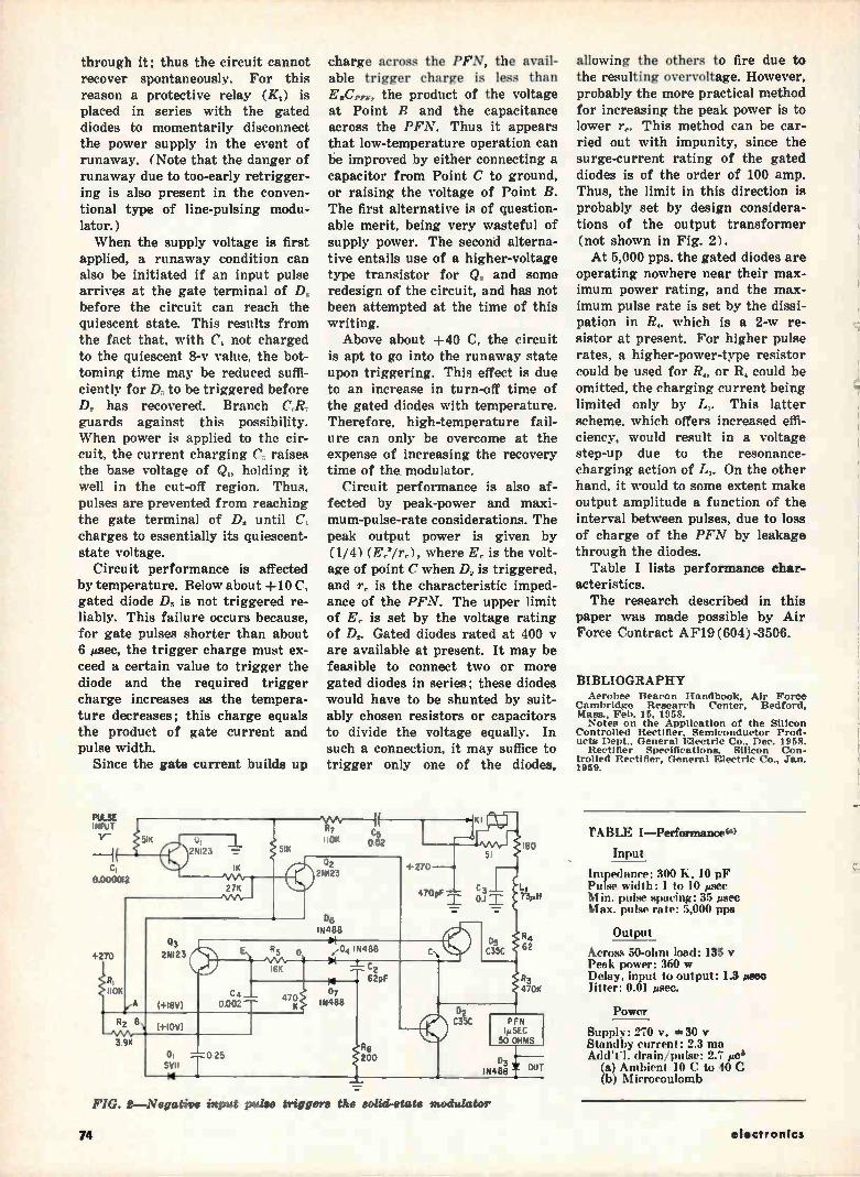
through it; thus the circuit cannot recover spontaneously. For this reason a protective relay (Ki) is placed in series with the gated diodes to momentarily disconnect the power supply in the event of runaway. (Note that the danger of runaway due to too-early retrigger-ing is also present in the conven-tional type of line-pulsing modu-lator.) When the supply voltage is first
applied, a runaway condition can also be initiated if an input pulse arrives at the gate terminal of D, before the circuit can reach the quiescent state. This results from the fact that, with C, not charged to the quiescent 8-v value, the bot-toming time may be reduced suffi-ciently for 1), to be triggered before D„ has recovered. Branch C:Rv guards against this possibility. When power is applied to the cir-cuit, the current charging C, raises the base voltage of Qi, holding it well in the cut-off region. Thus, pulses are prevented from reaching the gate terminal of D„ until C, charges to essentially its quiescent-state voltage.
Circuit performance is affected by temperature. Below about +10 C, gated diode D„ is not triggered re-liably. This failure occurs because, for gate pulses shorter than about 6 ¿sec, the trigger charge must ex-ceed a certain value to trigger the diode and the required trigger charge increases as the tempera-ture decreases; this charge equals the product of gate current and pulse width.
Since the gate current builds up
charge across the PFN, the avail-able trigger charge is less than
the product of the voltage at Point B and the capacitance across the PFN. Thus it appears that low-temperature operation can be improved by either connecting a capacitor from Point C to ground, or raising the voltage of Point B. The first alternative is of question-able merit, being very wasteful of supply power. The second alterna-tive entails use of a higher-voltage type transistor for Q, and some redesign of the circuit, and has not been attempted at the time of this writing. Above about +40 C, the circuit
is apt to go into the runaway state upon triggering. This effect is due to an increase in turn-off time of the gated diodes with temperature. Therefore, high-temperature fail-ure can only be overcome at the expense of increasing the recovery time of the modulator.
Circuit performance is also af-fected by peak-power and maxi-mum-pulse-rate considerations. The peak output power is given by (1/4) (E„'/r,), where E, is the volt-age of point C when D, is triggered, and r, is the characteristic imped-ance of the PFN. The upper limit of Ei. is set by the voltage rating of D,. Gated diodes rated at 400 y are available at present. It may be feasible to connect two or more gated diodes in series; these diodes would have to be shunted by suit-ably chosen resistors or capacitors to divide the voltage equally. In such a connection, it may suffice to trigger only one of the diodes,
PFN iµSEC
50 OHMS
allowing the others to fire due to the resulting overvoltage. However, probably the more practical method for increasing the peak power is to lower r„. This method can be car-ried out with impunity, since the surge-current rating of the gated diodes is of the order of 100 amp. Thus, the limit in this direction is probably set by design considera-tions of the output transformer (not shown in Fig. 2). At 5,000 pps. the gated diodes are
operating nowhere near their max-imum power rating, and the max-imum pulse rate is set by the dissi-pation in R,. which is a 2-w re-sistor at present. For higher pulse rates, a higher-power-type resistor could be used for R„ or R, could be omitted, the charging current being limited only by Li. This latter scheme, which offers increased effi-ciency, would result in a voltage step-up due to the resonance-charging action of Li. On the other hand, it would to some extent make output amplitude a function of the interval between pulses, due to loss of charge of the PFN by leakage through the diodes.
Table I lists performance char-acteristics. The research described in this
paper was made possible by Air Force Contract AF19 (604)-3506.
BIBLIOGRAPHY Aerobee Beacon Handbook, Air Force
Cambridge Research Center, Bedford, Mass., Feb. 15, 1958. Notes on the Application of the Silicon
Controlled Rectifier, Semiconductor Prod-ucts Dept., General Electric Co., Dec. 1958.
Rectifier Specifications, Silicon Con-trolled Rectifier, General Electric Co., Jan. 1969.
CABLE I—Performanceeo
Input
Impedance: 300 K. 10 pF Pulse width: 1 to 10 /Agee Min. pulse spacing: 35 psee Max. pulse rate: 5,000 pps
Output
Across 50-ohm load: 135 y Peak power: 360 w Delay, input to output: 1.3 Faso Titter: 0.01 asec.
Power
Supply: 270 y, 30 y Standby current: 2.3 ma Aden. drain/pulse: 2.7 peb
(a) Ambient 10 C to 40 C (b) Microcoulomb
FIG. 2—Negative input pulse triggers the solid-state modulator
74 electronics
our business is communications and control systems...
For over 75 years North Electric has been designing, engineering
and manufacturing "systems" designed on the dual functions of communications and control.
Today, North Systems speed man's thoughts and words over vast
distances, between continents and over oceans in seconds.
Today, North Systems control the flow of light, heat, power and
water for homes and industry, petroleum products for the wheels of America and chemicals for industry.
Today, North Systems are at work on land, sea and in the air as integral cogs in our vast transportation network.
Today, North Systems make possible high speed data processing
complexes functioning through highly efficient switching centrals.
Today, North Systems automate production tools and production
lines, handle packaging and pricing chores, perform scientific test-ing, measuring, weighing and analysis, and hosts of similar functions.
Today, North Systems help BMEWS guard our frontiers, add to our missile capability in projects THOR and JUPITER and help keep
our nation safe and strong in many other defense programs.
At North Electric, the engineering team represents a cadre of pro-
fessional competence with the solid background that comes from
long experience in the application of system concepts.
To learn what North can do for you, systemwise, today and tomor-
row, write for your copy of "North System Concepts" booklet—now.
ELECTRONETICS DIVISION
NORTH ELECTRIC COMPANY 647 S. Market St. Galion, Ohio
di> ‘&140
r4eg
NORTH
July 22, 1960 CIRCLE 75 ON READER SERVICE CARD 75
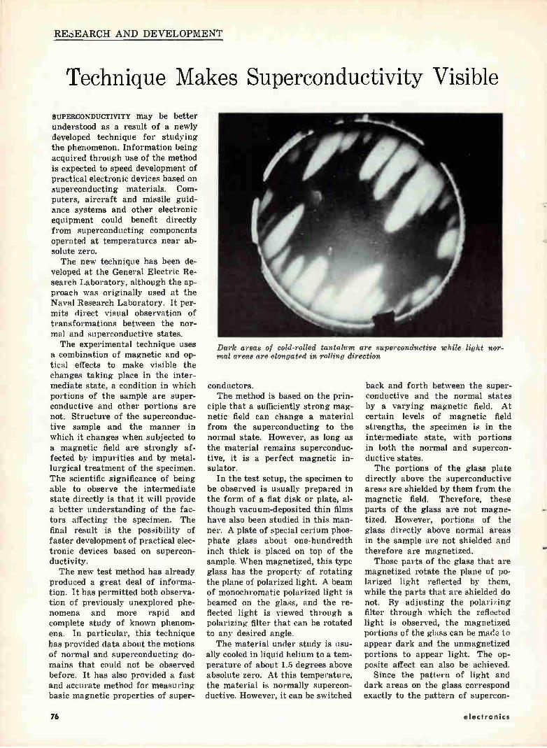
RESEARCH AND DEVELOPMENT
Technique Makes Superconductivity Visible
SUPERCONDUCTIVITY may be better understood as a result of a newly developed technique for studying the phenomenon. Information being acquired through use of the method is expected to speed development of practical electronic devices based on superconducting materials. Com-puters, aircraft and missile guid-ance systems and other electronic equipment could benefit directly from superconducting components operated at temperatures near ab-solute zero. The new technique has been de-
veloped at the General Electric Re-search Laboratory, although the ap-proach was originally used at the Naval Research Laboratory. It per-mits direct visual observation of transformations between the nor-mal and superconductive states. The experimental technique uses
a combination of magnetic and op-tical effects to make visible the changes taking place in the inter-mediate state, a condition in which portions of the sample are super-conductive and other portions are not. Structure of the superconduc-tive sample and the manner in which it changes when subjected to a magnetic field are strongly af-fected by impurities and by metal-lurgical treatment of the specimen. The scientific significance of being able to observe the intermediate state directly is that it will provide a better understanding of the fac-tors affecting the specimen. The final result is the possibility of faster development of practical elec-tronic devices based on supercon-ductivity. The new test method has already
produced a great deal of informa-tion. It has permitted both observa-tion of previously unexplored phe-nomena and more rapid and complete study of known phenom-ena. In particular, this technique has provided data about the motions of normal and superconducting do-mains that could not be observed before. It has also provided a fast and accurate method for measuring basic magnetic properties of super-
Dark areas of cold-rolled tantalum are superconductive while light nor-mal areas are elongated in rolling direction
conductors. The method is based on the prin-
ciple that a sufficiently strong mag-netic field can change a material from the superconducting to the normal state. However, as long as the material remains superconduc-tive, it is a perfect magnetic in-sulator.
In the test setup, the specimen to be observed is usually prepared in the form of a flat disk or plate, al-though vacuum-deposited thin films have also been studied in this man-ner. A plate of special cerium phos-phate glass about one-hundredth inch thick is placed on top of the sample. When magnetized, this type glass has the property of rotating the plane of polarized light. A beam of monochromatic polarized light is beamed on the glass, and the re-flected light is viewed through a polarizing filter that can be rotated to any desired angle. The material under study is usu-
ally cooled in liquid helium to a tem-perature of about 1.5 degrees above absolute zero. At this temperature, the material is normally supercon-ductive. However, it can be switched
back and forth between the super-conductive and the normal states by a varying magnetic field. At certain levels of magnetic field strengths, the specimen is in the intermediate state, with portions in both the normal and supercon-ductive states. The portions of the glass plate
directly above the superconductive areas are shielded by them from the magnetic field. Therefore, these parts of the glass are not magne-tized. However, portions of the glass directly above normal areas in the sample are not shielded and therefore are magnetized.
Those parts of the glass that are magnetized rotate the plane of po-larized light reflected by them, while the parts that are shielded do not. By adjusting the polarizing filter through which the reflected light is observed, the magnetized portions of the glass can be made to appear dark and the unmagnetized portions to appear light. The op-posite affect can also be achieved.
Since the pattern of light and dark areas on the glass correspond exactly to the pattern of supercon-
76 electronics
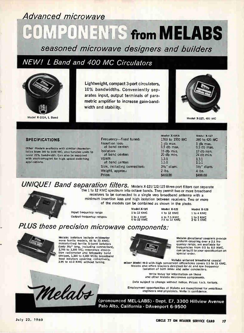
Advanced microwave «rei
from M ELABS4 seasoned microwave designers and builders
NEW! L Band and 400 MC Circulators
Lightweight, compact 3-port circulators,
10% bandwidths. Conveniently sep-
arates input, output terminals of para-
metric amplifier to increase gain-band-
width and stability.
Model X-101A, L Band Model X-I27, 400 MC
SPECIFICATIONS
Other models available with similar character-
istics from 360 to 3000 MC; also tunable units to
cover 25% bandwidth. Can also be supplied with electromagnet for high speed switching applications.
Frequency—fixed tuned: Insertion loss:
at band center: Isolation:
at band center: VSWR:
at band center: Size, including connectors: Weight, approx.: Price:
Model X-101A
1300 to 1500 MC 1 db max. 0.5 db max. 15 db min. 20 db min. 1.3:1 1.1:1 31/2 " diam. 2 lbs. $400-.00
Modal X-127
380 to 420 MC 1 db max. 0.5 db max. 17 db min. 24 db min. 1.3:1 1.1:1 51/2 " diam. 4 lbs. $400.00
UNIQUE! Band separation filters. Models X-121/122/123 three-port filters can separate the 1 to 12 KMC spectrum into octave bands. They permit two or more broadband
receivers to be connected to a single very broadband antenna with a minimum insertion loss and high isolation between receivers. Two or more
of the models can be combined as shown in the photo.
Input frequency range
Output frequency ranges:
Model X-121
1 to 12 KMC
1 to 4 KMC 4 to 12 KMC
Model X-122
4 to 12 KMC
4 to 7.5 KMC 7.5 to 12 KMC
PLUS these precision microwave components:
Melabs isolators include millimeter wave ferrite models, 66 to 73 KMC; miniaturized ferrite S-band isolators (only 312" long, including connectors), 2,700 to 3,100 MC; resonance absorp-tion radiometer and telemetry band devices, 1,330 to 2,360 MCS; broadband load isolators covering, collectively, 3.95 to 40.0 KMC without tuning.
Model X-123
1 to 4 KMC
1 to 2 KMC 2 to 4 KMC
Melabs directional couplers provide uniform coupling over a 2:1 fre-quency range, are available for frequencies from 0.5 to 8.0 KMC, can be built to your specification on special order.
Melabs untuned broadband coaxial mixer Model M-3 with high conversion efficiencies covers 0.5 to 11 KMC.
Melabs also offers blockers designed for dc and low frequency isolation of both inner and outer conductors.
Write today for information on these and other Melabs microwave components.
Data subject to change without notice. Prices f.o.b. factory.
Employment opportunities at Melabs are exceptional for ambitious engineers and physicists. Write in confidence.
(pronounced MEL-LABS) • Dept. E7, 3300 Hillview Avenue Palo Alto, California • DAvenport 6-9500
July 22, 1960 CIRCLE 77 ON READER SERVICE CARD 77
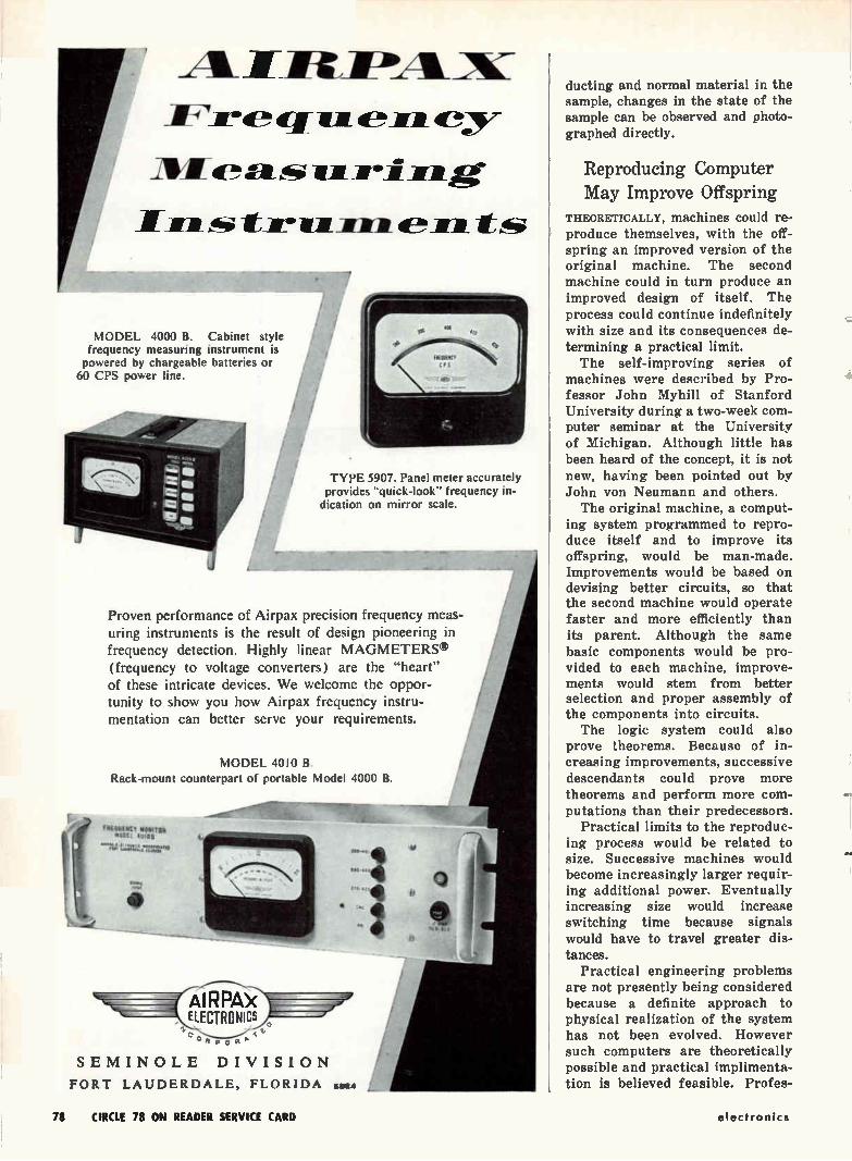
ifireIPALX 1/1/. V"
17_711*1 _Rea 7Mafretritm_Teite_me -tbs
MODEL 4000 B. Cabinet style frequency measuring instrument is powered by chargeable batteries or 60 CPS power line.
TYPE 5907. Panel meter accurately provides "quick-look" frequency in-
dication on mirror scale.
Proven performance of Airpax precision frequency meas-uring instruments is the result of design pioneering in frequency detection. Highly linear MAGMETERS® (frequency to voltage converters) are the "heart" of these intricate devices. We welcome the oppor-tunity to show you how Airpax frequency instru-mentation can better serve your requirements.
MODEL 4010 B. Rack-mount counterpart of portable Model 4000 B.
figitiflter Welt tip mew loll
4/
AIRPAk ELECTRONICS
SEMINOLE DIVISION
FORT LAUDERDALE, FLORIDA 5824
to
Of
ducting and normal material in the sample, changes in the state of the sample can be observed and photo-graphed directly.
Reproducing Computer May Improve Offspring
THEORETICALLY, machines could re-produce themselves, with the off-spring an improved version of the original machine. The second machine could in turn produce an improved design of itself. The process could continue indefinitely with size and its consequences de-termining a practical limit. The self-improving series of
machines were described by Pro-fessor John Myhill of Stanford University during a two-week com-puter seminar at the University of Michigan. Although little has been heard of the concept, it is not new, having been pointed out by John von Neumann and others. The original machine, a comput-
ing system programmed to repro-duce itself and to improve its offspring, would be man-made. Improvements would be based on devising better circuits, so that the second machine would operate faster and more efficiently than its parent. Although the same basic components would be pro-vided to each machine, improve-ments would stem from better selection and proper assembly of the components into circuits. The logic system could also
prove theorems. Because of in-creasing improvements, successive descendants could prove more theorems and perform more com-putations than their predecessors.
Practical limits to the reproduc-ing process would be related to size. Successive machines would become increasingly larger requir-ing additional power. Eventually increasing size would increase switching time because signals would have to travel greater dis-tances.
Practical engineering problems are not presently being considered because a definite approach to physical realization of the system has not been evolved. However such computers are theoretically possible and practical implimenta-tion is believed feasible. Profes-
78 CIRCLE 78 ON READER SERVICE CARD electronics
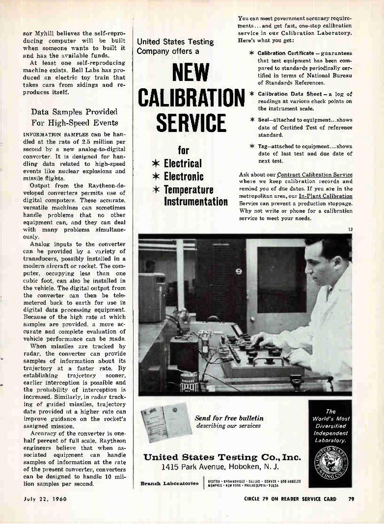
sor Myhill believes the self-repro-ducing computer will be built when someone wants to built it and has the available funds. At least one self-reproducing
machine exists. Bell Labs has pro-duced an electric toy train that takes cars from sidings and re-produces itself.
Data Samples Provided
For High-Speed Events
INFORMATION SAMPLES can be han-dled at the rate of 2.5 million per second by a new analog-to-digital converter. It is designed for han-dling data related to high-speed events like nuclear explosions and missile flights.
Output from the Raytheon-de-veloped converters permits use of digital computers. These accurate, versatile machines can sometimes handle problems that no other equipment can, and they can deal with many problems simultane-ously.
Analog inputs to the converter can be provided by a variety of transducers, possibly installed in a modern aircraft or rocket. The com-puter, occupying less than one cubic foot, can also be installed in the vehicle. The digital output from the converter can then be tele-metered back to earth for use in digital data processing equipment. Because of the high rate at which samples are provided, a more ac-curate and complete evaluation of vehicle performance can be made. When missiles are tracked by
radar, the converter can provide samples of information about its trajectory at a faster rate. By establishing trajectory sooner, earlier interception is possible and the probability of interception is increased. Similarly, in radar track-ing of guided missiles, trajectory data provided at a higher rate can improve guidance on the rocket's assigned mission.
Accuracy of the converter is one-half percent of full scale. Raytheon engineers believe that when as-sociated equipment can handle samples of information at the rate of the present converter, converters can be designed to handle 10 mil-lion samples per second.
United States Testing Company offers a
You can meet government accuracy require-ments ... and get fast, one-stop calibration service in our Calibration Laboratory. Here's what you get:
NEW CALIBRATION SERVICE
for * Electrical * Electronic * Temperature
Instrumentation
* Calibration Certificate — guarantees that test equipment has been com-pared to standards periodically cer-tified in terms of National Bureau of Standards References.
* Calibration Data Sheet — a log of readings at various check points on the instrument scale.
* Seal—attached to equipment.., shows date of Certified Test of reference standard.
* Tag—attached to equipment...shows date of last test and due date of next test.
Ask about our Contract Calibration Service where we keep calibration records and remind you of due dates. If you are in the metropolitan area, our In-Plant Calibration Service can prevent a production stoppage. Why not write or phone for a calibration service to meet your needs.
Send for free bulletin describing our services
United States Testing Co., Inc. 1415 Park Avenue, Hoboken, N. J.
I BOSTON • BROWNSVILLE • DALLAS • DENVER • Los MILES Branch Laboratories liEliPNIS • NEW YORK • PHILADELPHIA • TULSA
12
The World's Most Diversified Independent Laboratory.
July 22, 1960 CIRCLE 79 ON READER SERVICE CARD 79
COMPONENTS AND MATERIALS
Program Sets Up Materials Science Center THE ADVANCED Research Projects Agency, Department of Defense, disclosed that Cornell University, University of Pennsylvania, and Northwestern University have been selected to set up vastly enlarged programs for the expansion of basic research in the science of materials. Under an unprecedented long-
term contract Cornell will receive $6.1 million for the first four years of this program, according to Cor-nell President Deane W. Malott. The contract provides for inter-
disciplinary research and graduate student training in materials, and will combine the efforts of portions of five departments in two colleges at Cornell. Cornell University will organize a Materials Science Center to administer the ARPA contract and to expand basic research and training of Ph. D. research scien-tists in materials.
"Materials science" is the investi-gation of physical and chemical processes in solids such as metals. The design of new materials for nuclear reactors, rocket engines, transistors, and other modern de-vices is based on this knd of re-search.
Cornell will construct a new $4-million building on its campus within the next three years. The building will house graduate re-search of the Laboratory of Atomic and Solid State Physics, the ad-ministrative offices of the Center, and several of the common technical facilities such as electron micro-scopes. ARPA will reimburse Cor-• nell for construction costs of this building over a 10-year period after it is occupied.
Cornell may build a substantially larger building, of which the ARPA construction would be a part, to house in addition a physics and chemistry library and some of the other activities of the Department of Physics. The four-year headway of the
ARPA-Cornell pact will be main-tained—the fifth year's financial support to be discussed next fall, and further support annually.
A substantial part of the $6.1-million contract will go into re-search equipment, including about $700.000 for individual research projects and $1.2 million for com-mon facilities. The facilities will permit Cornell graduate students and staff to work with the most modern physical, chemical, and metallurgical techniques available. The basic research scientists
who comprise the initial staff of the Center also will have use of a new atomic reactor being build by the University, the new $5.7-million research library nearing comple-tion, and other outstanding facili-ties already extant at Cornell. The staff of the ARPA project
will be faculty members and re-search associates already at the University. Additional faculty will be added during the next few years. Teaching and supervision of gradu-ate student research will continue to be the main tasks of these scien-tists.
Initially, the work of the Labora-tory of Atomic and Solid State Physics will comprise the largest part of the Center. This Labora-tory, which was organized a year ago, includes faculty and graduate students from the Department of Physics and the Department of En-gineering Physics. Later, the greater growth of Metallurgical Engineering and Engineering Me-chanics and Materials will make these departments equally import-ant.
Cornell was one of the first uni-versities to enter solid state physics, which generally was not recognized as a distinct science until after World War II. Substan-tial parts of the work at Cornell are concerned with imperfections, transport processes, magnetic res-onances, internal friction, photo-chemical processes, surface phe-nomena, ferroelectrics, magnetic phenomena in dilute alloys, optical processes in the far ultraviolet, X-rays, cooperative phenomena, ferromagnetism, man y-particle theory, and thermal conductivity.
A second area of emphasis in the Center is chemistry, with about a quarter of the current staff. This research is concerned with electron and X-ray diffraction, inorganic polymers, solid-vapor reactions, electronic processes in oxides, dif-fusion in polymers, polymers under high pressure, catalysis, photocon-ductivity, and theoretical physical chemistry. The third participating field of
endeavor is metallurgy, with about a sixth of the staff work on metal-lurgical science in the fields of intermetallic compounds, freez-ing transformations, solid-solution strengthening, nucleation, proper-ties of and phenomena in iron-base alloys, plastic deformation, and fracture. The fourth substantial research
area represented is mechanics and materials, making up a tenth of the staff. Scientists in this field will deal with elastic constants as func-tions of pressure, ferroelectrics un-der impulse loading, and diffusion and creep under hydrostatic pres-sure. The number of professors in the
Center will be increased from about 30 to about 60 in the next ten years. Four more areas of scientific inves-tigation, namely mathematics, in-dustrial engineering, geology, and electrical engineering, probably will be added to the Center's research program in the near future. The Cornell Materials Science
Center will enable interdisciplinary cooperation in the fields mentioned, and the increased staff will permit the University to train about twice as many Ph.D. scientists in these areas of study. The entire research program conducted by the new Cen-ter will be integrated with the pro-gram for training graduate stu-dents on a personal basis in the use of methods and equipment that will be as modern as that in any indus-trial laboratory. The organization of the Materials
Science Center is not a substitute for the conventional organization of colleges, departments, and divi-
•••
80 electronics
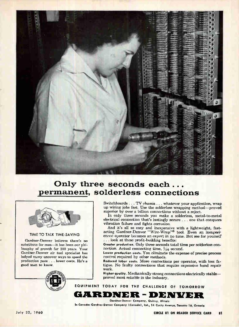
Only three seconds each... permanent,
TIME TO TALK TIME-SAVING
Gardner-Denver believes there's no substitute for men—it has been our phi-losophy of growth for 100 years. Your Gardner-Denver air tool specialist has helped many uncover ways to speed the production pace . . . lower costs. He's a good man to know.
solderless connections
Switchboards . . . TV chassis . . . whatever your application, wrap up wiring jobs fast. Use the solderless wrapping method—proved superior by over a billion connections without a reject.
In only three seconds you make a solderless, metal-to-metal electrical connection that's lastingly secure . . . one that conquers vibration failure and fights corrosion. And it's all so easy and inexpensive with a lightweight, fast-
acting Gardner-Denver "Wire-Wrap"® tool. Even an inexperi-enced operator becomes an expert in no time. But see for yourself . . . look at these profit-building benefits: Greater production. Only three seconds total time per solderless con-nection. Actual connecting time, to second. Lower production costs. You eliminate the expense of precise process control required by other methods. Reduced labor costs. More connections per operator, with less fa-tigue. No faulty connections that require expensive hand repair work. Higher quality. Mechanically strong connections electrically stable— proved most reliable in the industry.
EQUIPMENT TODAY FOR THE CHALLENGE OF TOMORROW
GARDNER - DENVER Gardner-Denver Company, Quincy, Illinois
In Canada: Gardner-Denver Company (Canada), Ltd., 14 Curity Avenue, Toronto 16, Ontario
July 22, 1960 CIRCLE 81 ON READER SERVICE CARD 81
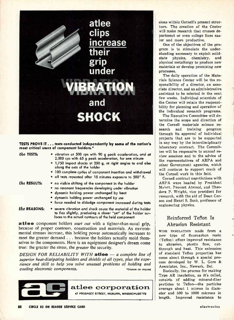
atlee clips increase their grip under
161Menatt and
SHOCK
TESTS PROVE IT ... tests conducted independently by some of the nation's most critical users of component holders.*
the TESTS:
the RESULTS:
the REASONS:
• vibration at 500 cps with 90 g peak acceleration, and at 2,000 cps with 65 g peak acceleration, for one minute
• 1,750 impact shocks at 200 g, at right angles to and also along the axis of the holder
• 100 complete cycles of component insertion and withdrawal
• all tests repeated after 15 minutes exposure to 500' F.
• no visible shifting of the component in the holder • no resonant frequencies developing under vibration
• dynamic holding power unchanged by heat • dynamic holding power unchanged by use
• force needed to dislodge component increased during tests
• severe vibration and shock cause the material of the holder to flex slightly, producing a closer "set" of the holder sur-faces to the actual contours of the held component
atlee component holders start out with a tighter-than-usual grip, because of proper contours, construction and materials. As environ-mental stresses increase, this holding power automatically increases to meet the greater demand . . . because the holders actually mold them-selves to the components. Here is an equipment designer's dream come true: the greater the stress, the greater the security.
DESIGN FOR RELIABILITY WITH atlee — a complete line of superior heat-dissipating holders and shields of all types, plus the expe-rience and skill to help you solve unusual problems of holding and cooling electronic components. *Names on request
a.tlee c Qi-pceration. 47 PROSPECT STREET, WOBURN, MASSACHUSETTS
sions within Cornell's present struc-ture. The creation of the Center will make research that crosses de-partment or even college lines eas-ier and more productive. One of the objectives of the pro-
gram is to stimulate the under-standing necessary to exploit solid-state physics, chemistry, and physical metallurgy to produce new materials or develop promising new processes. The daily operation of the Mate-
rials Science Center will be the re-sponsibility of a director, an asso-ciate director, and an administrative assistant to be selected in the next few weeks. Individual scientists of the Center will retain the responsi-bility for planning and operation of the individual research programs. The Executive Committee will de-
termine the scope and direction of the Cornell materials science re-search and training program through its approval of individual projects that are to be supported in any way by the interdisciplinary laboratory contract. The Commit-tee will be responsive to annual re-view sessions and to the advice of the representatives of ARPA and other Government agencies, which will continue to support much of the Cornell work in this field.
Cornell contract negotiations with ARPA were headed by President
Provost Atwood, and Theo-dore P. Wright, vice president for research, with the aid of Dean Cor-son and Henri S. Sack, professor of engineering physics.
Reinforced Teflon Is Abrasion Resistant
WIRE INSULATION made from a new type of fluorcarbon resin (Teflon) offers improved resistance to abrasion, plastic flow, cut-through and heat. This extension of standard Teflon properties has come about through a special pro-cess developed by W. L. Gore & Associates, Inc., Newark, Del.
Basically, the process for making Type AR insulation, as it's called, consists of adding mineral-fiber particles to Teflon—the particles average about 1 micron in diam-eter and 500 to 1000 microns in length. Improved resistance to
82 CIRCLE 82 ON READER SERVICE CARD electronics
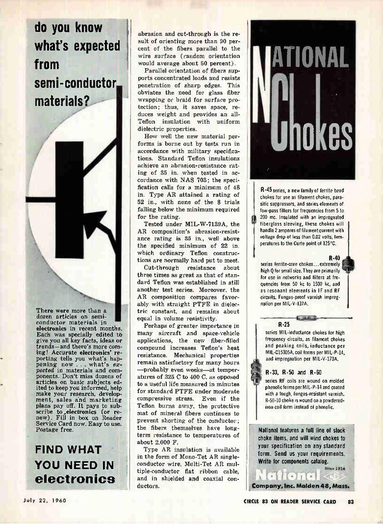
do you know what's expected from semi-conductor materials?
There were more than a dozen articles on semi-conductor materials in electronics in recent months. Each was specially edited to give you all key facts, ideas or trends—and there's more com-ing! Accurate electronics' re-porting tells you what's hap-pening now . . . what's ex-pected in materials and com-ponents. Don't miss dozens of articles on basic subjects ed-ited to keep you informed, help make your research, develop-ment, sales and marketing plans pay off. It pays to sub-scribe to ,electronics (or re-new). Fill in box on Reader Service Card now. Easy to use. Postage free.
FIND WHAT
YOU NEED IN
electronics
abrasion and cut-through is the re-sult of orienting more than 90 per-cent of the fibers parallel to the wire surface (random orientation would average about 50 percent).
Parallel orientation of fibers sup-ports concentrated loads and resists penetration of sharp edges. This obviates the need for glass fiber wrapping or braid for surface pro-tection; thus, it saves space, re-duces weight and provides an all-Teflon insulation with uniform dielectric properties. How well the new material per-
forms is borne out by tests run in accordance with military specifica-tions. Standard Teflon insulations achieve an abrasion-resistance rat-ing of 35 in. when tested in ac-cordance with NAS 703; the speci-fication calls for a minimum of 48 in. Type AR attained a rating of 52 in., with none of the 8 trials falling below the minimum required for the rating.
Tested under MIL-W-7139A, the AR composition's abrasion-resist-ance rating is 35 in., well above the specified minimum of 22 in. which ordinary Teflon construc-tions are normally hard put to meet.
Cut-through resistance about three times as great as that of stan-dard Teflon was established in still another test series. Moreover, the AR composition compares favor-ably with straight PTFE in dielec-tric constant, and remains about equal in volume resistivity.
Perhaps of greater importance in many aircraft and space-vehicle applications, the new fiber-filled compound increases Teflon's heat resistance. Mechanical properties remain satisfactory for many hours —probably even weeks—at temper-atures of 325 C to 400 C, as opposed to a useful life measured in minutes for standard PTFE under moderate compressive stress. Even if the Teflon burns away, the protective mat of mineral fibers continues to prevent shorting of the conductor; the fibers themselves have long-term resistance to temperatures of about 2,000 F. Type AR insulation is available
in the form of Mono-Tet AR single-conductor wire, Multi-Tet AR mul-tiple-conductor fiat ribbon cable, and in shielded and coaxial con-ductors.
IIATIONAL
rielIOLGS
R-45 series, a new family of ferrite bead chokes for use as filament chokes, para-sitic suppressors, and series elements of low-pass filters for frequencies from 5 to 200 mc. Insulated with an impregnated fiberglass sleeving, these chokes will handle 2 amperes of filament current with voltage drop of less than 0.02 volts, tem-peratures to the Curie point of 125°C.
R-40 series ferrite-core chokes.., extremely high Q for small size. They are primarily for use in networks and filters at fre-quencies from 50 kc to 1500 kc, and as resonant elements in IF and RF circuits. Fungus-proof varnish impreg-nation per MIL-V-137A.
R-25 series MIL-inductance chokes for high frequency circuits, as filament chokes and peaking coils, inductance per MIL-C15305A, coil forms per MIL-P-14, and impregnation per MIL-V-173A.
R-33, R - 50 and R - 60
series RF coils are wound on molded phenolic forms per MIL-P-14 and coated with a tough, fungus-resistant varnish. R-50-10 choke is wound on a powdered-iron coil form instead of phenolic.
National features a full line of stock choke items, and will wind chokes to your specification on any standard form. Send us your requirements. Write for components catalog.
Since 1914
fitif ti GI 4 ro ;Y; 1 Company, Inc. Malden 48, Mass.
)uly 22, 1960 CIRCLE 83 ON READER SERVICE CARD 83
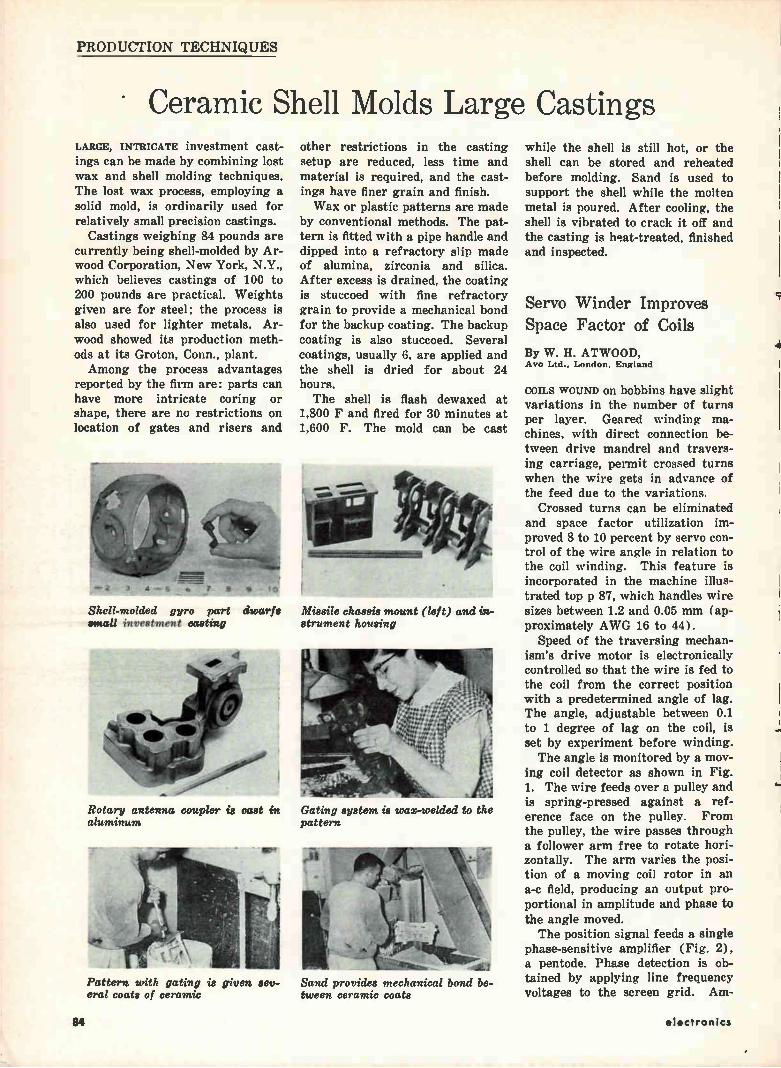
PRODUCTION TECHNIQUES
Ceramic Shell Molds Large Castings LARGE, INTRICATE investment cast-ings can be made by combining lost wax and shell molding techniques. The lost wax process, employing a solid mold, is ordinarily used for relatively small precision castings.
Castings weighing 84 pounds are currently being shell-molded by Ar-wood Corporation, New York, N.Y., which believes castings of 100 to 200 pounds are practical. Weights given are for steel; the process is also used for lighter metals. Ar-wood showed its production meth-ods at its Groton, Conn., plant. Among the process advantages
reported by the firm are: parts can have more intricate coring or shape, there are no restrictions on location of gates and risers and
other restrictions in the casting setup are reduced, less time and material is required, and the cast-ings have finer grain and finish. Wax or plastic patterns are made
by conventional methods. The pat-tern is fitted with a pipe handle and dipped into a refractory slip made of alumina, zirconia and silica. After excess is drained, the coating is stuccoed with fine refractory grain to provide a mechanical bond for the backup coating. The backup coating is also stuccoed. Several coatings, usually 6. are applied and the shell is dried for about 24 hours. The shell is flash dewaxed at
1,800 F and fired for 30 minutes at 1,600 F. The mold can be cast
Shell-molded gyro part dwarfs Missile chassis mount (left) and in-small investment casting atrument housing
Rotary antenna coupler is cast in Gating system is wax-welded to the aluminum pattern
Pattern with gating is given sev-eral coats of ceramic
Sand provides mechanical bond be-tween ceramic coats
while the shell is still hot, or the shell can be stored and reheated before molding. Sand is used to support the shell while the molten metal is poured. After cooling, the shell is vibrated to crack it off and the casting is heat-treated, finished and inspected.
Servo Winder Improves Space Factor of Coils
By W. H. ATWOOD, Ayo Ltd., London. England
COILS WOUND on bobbins have slight variations in the number of turns per layer. Geared winding ma-chines, with direct connection be-tween drive mandrel and travers-ing carriage, permit crossed turns when the wire gets in advance of the feed due to the variations.
Crossed turns can be eliminated and space factor utilization im-proved 8 to 10 percent by servo con-trol of the wire angle in relation to the coil winding. This feature is incorporated in the machine illus-trated top p 87, which handles wire sizes between 1.2 and 0.05 mm (ap-proximately AWG 16 to 44).
Speed of the traversing mechan-ism's drive motor is electronically controlled so that the wire is fed to the coil from the correct position with a predetermined angle of lag. The angle, adjustable between 0.1 to 1 degree of lag on the coil, is set by experiment before winding. The angle is monitored by a mov-
ing coil detector as shown in Fig. 1. The wire feeds over a pulley and is spring-pressed against a ref-erence face on the pulley. From the pulley, the wire passes through a follower arm free to rotate hori-zontally. The arm varies the posi-tion of a moving coil rotor in an a-c field, producing an output pro-portional in amplitude and phase to the angle moved. The position signal feeds a single
phase-sensitive amplifier (Fig. 2), a pentode. Phase detection is ob-tained by applying line frequency voltages to the screen grid. Am-
electronics
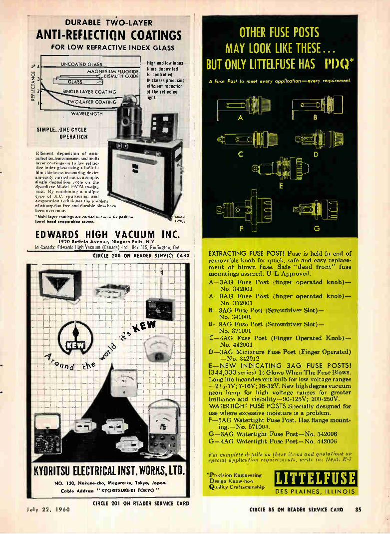
KYORITSU ELECTRICAL INST. WORKS, LTD.
DURABLE TWO-LAYER
ANTI-REFLECTION COATINGS
e 4 o
Z 3
o t±.1 2
FOR LOW REFRACTIVE INDEX GLASS
UNCOATED GLASS
MAGNESIUM FLUORIDE BISMUTH OXIDE
SINGLE-LAYER COATING
WO-LAYER COATING
WAVELENGTH
SIMPLE...ONE-CYCLE
OPERATION
Efficient deposition of antireflection,transmission, and multi
layer coatings on to low refrac-tive index glass using a built in film thickness measuring device are easily carried out in a simple, single deposition cycle on the Speedivac Model 19VErt coating unit. By combining a unique type of A.C. sputtering, and evaporation techniques the problem of absorption free and durable filma have been overcome.
'Multi loyer coatings are carried out on a six position turret head evaporation source.
High and low index films deposited to controlled thickness producing efficient reduction of the reflected fight.
model I 9 VE5
EDWARDS HIGH VACUUM INC. 1920 Buffalo Avenue, Niagara Falls, N.Y.
In Canada: Edwards High Vacuum (Canada) Ltd., Box 515. Burlington, Ont.
CIRCLE 200 ON READER SERVICE CARD
I
NO. 120, Nokone-cho, Meguro-ku, Tokyo, iopon.
Cable Address " KYORITSUKEIKI TOKYO "
OTHER FUSE POSTS MAY LOOK LIKE THESE...
BUT ONLY LITTELFUSE HAS 19(,)* A Fuse Post to meet every application—every requirement.
A
E
corCle.1
G
EXTRACTING FUSE POST! Fuse is held in end of removable knob for quick, safe and easy replace-ment of blown fuse. Safe "dead front" fuse mountings assured. U 'L Approved.
A-3AG Fuse Post (finger operated knob)— No. 342001
A-8AG Fuse Post (finger operated knob)— No. 372001
B-3AG Fuse Post (Screwdriver Slot)— No. 341001
B-8AG Fuse Post (Screwdriver Slot)— No. 371001
C-4AG Fuse Post (Finger Operated Knob)— No. 442001
D-3AG Miniature Fuse Post (Finger Operated) —No. 342012
E— NEW INDICATING 3AG FUSE POSTS! (344,000 series) It Glows When The Fuse Blows. Long life incandescent bulb for low voltage ranges —23 --7V; 7-16V; 16-32V. New high degree vacuum neon lamp for high voltage ranges for greater brilliance and visibility-90-125V; 200-250V. WATERTIGHT FUSE POSTS Specially designed for use where excessive moisture is a problem. F-5AG Watertight Fuse Post. Has flange mount-
ing.—No. 571004. • G —3AG Watertight Fuse Post—No. 342006 G —4AG Watertight Fuse Post—No. 442006
For complete details on Deese items and quotations on special application requirements, write to: Dept. E-7
'Precision Engineering Design Know-how Quality Craftsmanship
LITTELFUSE DES PLAINES, ILLINOIS
CIRCLE 201 ON READER SERVICE CARD July 22, 19/',0 CIRCLE CS ON READER SERVICE CARD 85
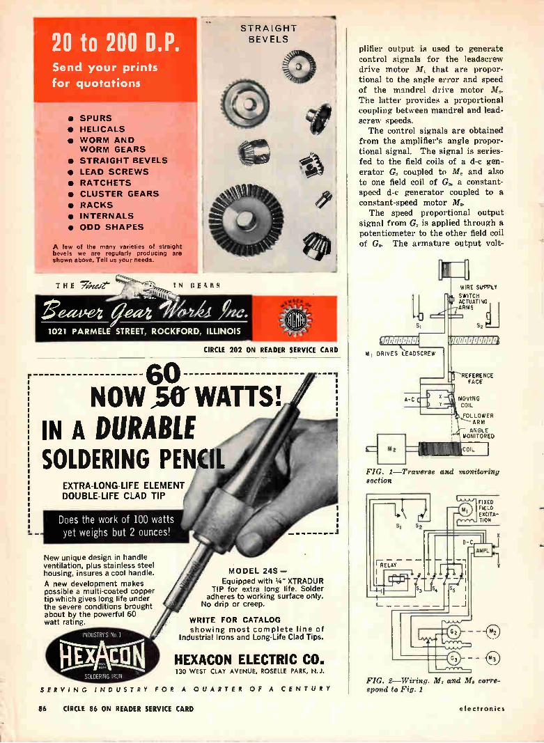
• SPURS
• HELICALS
• WORM AND WORM GEARS
• STRAIGHT BEVELS
• LEAD SCREWS
• RATCHETS
• CLUSTER GEARS
• RACKS
• INTERNALS
• ODD SHAPES
A few of the many varieties of straight bevels we are regularly producing are shown above. Tell us your needs.
T H E 7:,e,:ve-I g
eeeeeen eeZdà
I N E \ ti
1021 PARMELE STREET, ROCKFORD, ILLINOIS
L -
60
STRAIGHT BEVELS
I
CIRCLE 202 ON READER SERVICE CARD
NOW31YWATTS! IN A DURABLE SOLDERING PENCIL
EXTRA-LONG-LIFE ELEMENT DOUBLE-LIFE CLAD TIP
Does the work of 100 watts yet weighs but 2 ounces!
New unique design in handle ventilation, plus stainless steel housing, insures a cool handle.
A new development makes possible a multi-coated copper tip which gives long life under the severe conditions brought about by the powerful 60 watt rating.
INDUSTRYS No I
SOLDERING IRON
SERVING INDUST AY FOR A QUARTER OF A CENTURY
MODEL 24S —
Equipped with 1/4" XTRADUR TIP for extra long life. Solder
adheres to working surface only. No drip or creep.
WRITE FOR CATALOG showing most complete line of
Industrial Irons and Long-Life Clad Tips.
HEXACON ELECTRIC CO. 130 WEST CLAY AVENUE, ROSELLE PARK, N.J.
plifier output is used to generate
control signals for the leadscrew drive motor M, that are propor-tional to the angle error and speed of the mandrel drive motor M,. The latter provides a proportional coupling between mandrel and lead-screw speeds. The control signals are obtained
from the amplifier's angle propor-tional signal. The signal is series-fed to the field coils of a d-c gen-erator G1 coupled to M. and also to one field coil of G., a constant-speed d-c generator coupled to a constant-speed motor M..
The speed proportional output signal from G, is applied through a potentiometer to the other field coil of G. The armature output volt-
uJ SI
Id 1 DRIVES LEADSCREW
A-C
3
FIG. 1—Traverse and monitoring section
W RE SkIPPO
SWITCH ACTUATING ARMS
REFERENCE FACE
MOVING COIL
FOLLOWER ARM
ANGLE MONITORED
FIXED FIELD EXCITA-TION
FIG. 2—Wiring 111, and M. corre-spond to Fig. 1
86 CIRCLE 86 ON READER SERVICE CARD electronics
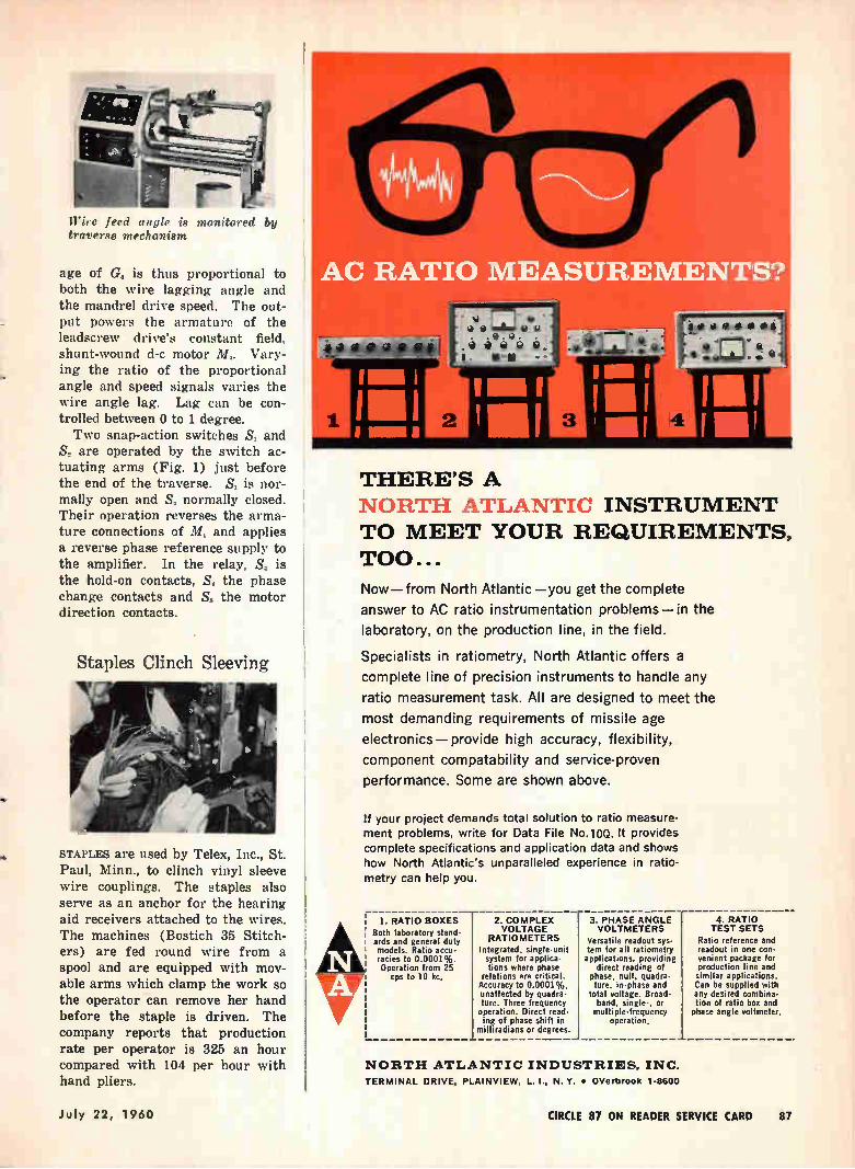
e.
Wire feed angle is monitored by traverse mechanism
age of G, is thus proportional to both the wire lagging angle and the mandrel drive speed. The out-put powers the armature of the leadscrew drive's constant field, shunt-wound d-c motor M,. Vary-ing the ratio of the proportional angle and speed signals varies the wire angle lag. Lag can be con-trolled between 0 to 1 degree. Two snap-action switches S, and
S, are operated by the switch ac-tuating arms (Fig. 1) just before the end of the traverse. S, is nor-mally open and S„ normally closed. Their operation reverses the arma-ture connections of Mi and applies a reverse phase reference supply to the amplifier. In the relay, S, is the hold-on contacts, S. the phase change contacts and S, the motor direction contacts.
Staples Clinch Sleeving
STAPLES are used by Telex, Inc., St. Paul, Minn., to clinch vinyl sleeve wire couplings. The staples also serve as an anchor for the hearing aid receivers attached to the wires. The machines (Bostich 35 Stitch-ers) are fed round wire from a spool and are equipped with mov-able arms which clamp the work so the operator can remove her hand before the staple is driven. The company reports that production rate per operator is 325 an hour compared with 104 per hour with hand pliers.
AC RATIO EASUREMENTS?
domoi
a • d i oi tI Olt
s.
I Ti Ili, 1 3mu far
THERE'S A
NORTH ATLANTTO INSTRUMENT
TO MEET YOUR REQUIREMENTS,
TOO...
Now—from North Atlantic —you get the complete
answer to AC ratio instrumentation problems—in the
laboratory, on the production line, in the field.
Specialists in ratiometry, North Atlantic offers a complete line of precision instruments to handle any
ratio measurement task. All are designed to meet the
most demanding requirements of missile age
electronics— provide high accuracy, flexibility,
component compatability and service-proven
performance. Some are shown above.
If your project demands total solution to ratio measure-ment problems, write for Data File No.10Q. It provides
complete specifications and application data and shows
how North Atlantic's unparalleled experience in ratio-
metry can help you.
I. RATIO BOXES Both laboratory stand-ards and general duty models. Ratio accu-racies to 0.0001 ,/o. Operation from 25
cps to 10 kc.
2. COMPLEX VOLTAGE
RATIOMETERS
Integrated, single-unit system for applica-tions where phase
relations are critical. Accuracy to 0.0001%, unaffected by quadra-ture. Three frequency operation. Direct read-ing of phase shift in
milliradians or degrees.
3. PHASE ANGLE VOLTMETERS
Versatile readout sys-tem for all ratiometry applications, providing
direct reading of phase, null, quadra-ture, in-phase and
total voltage. Broad-band, single-, or multiple-frequency
operation,
4. RATIO TEST SETS
Ratio reference and readout in one con-venient package for production line and similar applications. Can be supplied with any desired combina-tion of ratio box and phase angle voltmeter.
NORTH ATLANTIC INDUSTRIES, INC.
TERMINAL DRIVE, PLAINVIEW, L. t,. N. Y. • OVerbrook 1-8600
July 22, 1960 CIRCLE 87 ON READER SERVICE CARD 87
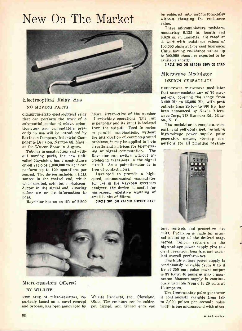
New On The Market
Electrooptical Relay Has NO MOVING PARTS
CIGARETTE-SIZED electrooptical relay that can perform the work of a substantial portion of relays, poten-tiometers and commutators pres-ently in use will be introduced by Raytheon Company, Industrial Com-ponents Division, Newton 58, Mass., at the Wescon Show in August. Tubular in construction and with-
out moving parts, the new unit, called Raysistor, has a conductance on-off ratio of 1,000,000 to 1; it can perform up to 100 operations per second. The device includes a light source in the control end, which when excited, actuates a photocon-ductor in the signal end, allowing either a-c or d-c information to pass.
Raysistor has an on life of 2,500
hours, irrespective of the number of switching operations. The unit is nonpolar and its input is isolated from the output. Used in series or parallel combinations, without the introduction of common-ground problems, it may be applied to logic circuits and matrices for telemeter-ing or signal commutation. The Raysistor can switch without in-troducing transients in the signal circuit. As a potentiometer it is free of contact noise.
Developed to provide a high-speed, nonmechanical commutator for use in the Rayspan spectrum analyzer, the device is useful for high-speed repetitive scanning of small banks of filters.
CIRCLE 301 ON READER SERVICE CARD
erdenut\
1,
Micro-resistors Offered BY WILRITE
NEW LINE of micro-resistors, re-portedly based on a novel concept and process, has been announced by
Wilrite Products, Inc., Cleveland, Ohio. The resistors can be solder-pot dipped, and tinned ends can
be soldered into submicromodules without changing the resistance value. These microminiature resistors,
measuring 0.125 in. length and 0.020 in. in diameter, are rated at
watt with resistance values of 100,000 ohms at 1-percent tolerance. Units having resistance values up to 500,000 ohms are expected to be available shortly.
CIRCLE 302 ON READER SERVICE CARD
Microwave Modulator DESIGN VERSATILITY
IIIGH-POWER microwave modulator that accommodates any of 76 mag-netrons, covering the range from 5,400 Mc to 35,000 Mc, with peak outputs from 20 Kw to 500 Kw, has been announced by Narda Micro-wave Corp., 118 Herricks Rd., Mine-ola, N. Y. The modulator is complete, com-
pact, and self-contained, including high-voltage power supply, pulse generator, meters, viewing con-nections for all principal parame-
ters, controls and protective cir-cuits. Provision is made for inter-nal mounting of the desired mag-netron. Silicon rectifiers in the high-voltage power supply give effi-cient operation, long life, and excel-lent overall performance. The high-voltage power supply is
continuously variable from 0 to 8 Kv at 200 ma; pulse power output is 37 Kv at 40 amperes max.; mag-netron filament supply is continu-ously variable from 0 to 20 volts at 16 amperes. The free-running pulse generator
is continuously variable from 180 to 3,000 pulses per second; pulse width is one microsecond with other
u electronics
FALCON MISSILE
Playing follow-the-leader at 50 millisecond intervals, three Super Falcon missiles rocket ahead of their diamond-shaped supersonic shock waves. Homing in on radar, these deadly air-to-air missiles locate, track, and destroy their prey, with the same killer instinct of the birds they're named after.
Hughes Aircraft, the developer and manufacturer of these missiles and the Arma-ment Control System that triggers them, specified Hitemp magnet and Teflon* wire for their missile, and Teflon wire for its control system.
Hitemp Wires, Inc., the leading specialist in high temperature insulated wires and cables, proudly answers roll call with those developers and manufacturers enlisted in defending our American birthright—Freedom.
HITEIVIP WIRES, INC. 1200 SHAMES DRIVE, WESTBURY, NEW YORK
*Registered trademark for DuPont fluorocarbon resin&
July 22, 1960 CIRCLE 89 ON READER SERVICE CARD 89
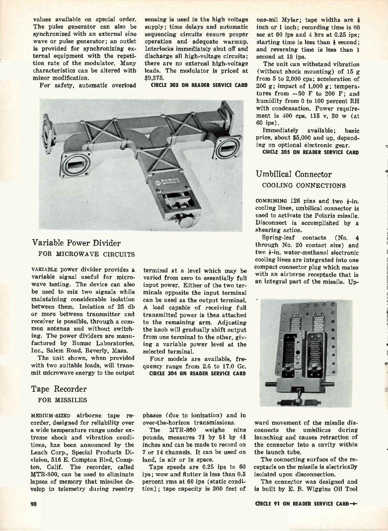
values available on special order. The pulse generator can also be synchronized with an external sine wave or pulse generator; an outlet is provided for synchronizing ex-ternal equipment with the repeti-tion rate of the modulator. Many characteristics can be altered with minor modification. For safety, automatic overload
Variable Power Divider FOR MICROWAVE CIRCUITS
VARIABLE power divider provides a variable signal useful for micro-wave testing. The device can also be used to mix two signals while maintaining considerable isolation between them. Isolation of 25 db or more between transmitter and receiver is possible, through a com-mon antenna and without switch-ing. The power dividers are manu-factured by Bomac Laboratories, Inc., Salem Road, Beverly, Mass. The unit shown, when provided
with two suitable loads, will trans-mit microwave energy to the output
Tape Recorder FOR MISSILES
MEDIUM-SIZED airborne tape re-corder, designed for reliability over a wide temperature range under ex-treme shock and vibration condi-tions, has been announced by the Leach Corp., Special Products Di-vision, 516 E. Compton Blvd, Comp-ton, Calif. The recorder, called MTR-800, can be used to eliminate lapses of memory that missiles de-velop in telemetry during reentry
sensing is used in the high voltage supply; time delays and automatic sequencing circuits ensure proper operation and adequate warmup. Interlocks immediately shut off and discharge all high-voltage circuits; there are no external high-voltage leads. The modulator is priced at $9,375.
CIRCLE 303 ON READER SERVICE CARD
terminal at a level which may be varied from zero to essentially full input power. Either of the two ter-minals opposite the input terminal can be used as the output terminal. A load capable of receiving full transmitted power is then attached to the remaining arm. Adjusting the knob will gradually shift output from one terminal to the other, giv-ing a variable power level at the selected terminal. Four models are available, fre-
quency range from 2.6 to 17.0 Ge. CIRCLE 304 ON READER SERVICE CARD
phases (due to ionization) and in over-the-horizon transmissions. The MTR-800 weighs nine
pounds, measures 78 by 5 î by zit inches and can be made to record on 7 or 14 channels. It can be used on land, in air or in space. Tape speeds are 0.25 ips to 60
ips; wow and flutter is less than 0.5 percent rms at 60 ips (static condi-tion) ; tape capacity is 300 feet of
one-mil Mylar; tape widths are I inch or 1 inch; recording time is 60 sec at 60 ips and 4 hrs at 0.25 ips; starting time is less than 1 second; and reversing time is less than 1 second at 15 ips. The unit can withstand vibration
(without shock mounting) of 15 g from 5 to 2,000 cps; acceleration of 200 g; impact of 1,000 g; tempera-tures from —50 F to 200 F; and humidity from 0 to 100 percent RH with condensation. Power require-ment is 400 cps, 115 v, 30 w (at 60 ips).
Immediately available; basic price, about $5,000 and up, depend-ing on optional electronic gear.
CIRCLE 305 ON READER SERVICE CARD
Umbilical Connector COOLING CONNECTIONS
COMBINING 126 pins and two 1-in. cooling lines, umbilical connector is used to activate the Polaris missile. Disconnect is accomplished by a shearing action.
Spring-leaf contacts (No. 4 through No. 20 contact size) and two 1-in, water-methanol electronic cooling lines are integrated into one compact connector plug which mates with an airborne receptacle that is an integral part of the missile. Up-
ward movement of the missile dis-connects the umbilicus during launching and causes retraction of the connector into a cavity within the launch tube. The connecting surface of the re-
ceptacle on the missile is electrically isolated upon disconnection. The connector was designed and
is built by E. B. Wiggins Oil Tool
90 CIRCLE 91 ON READER SERVICE CARD

amegeil se go y
immui
Specifications I Model 125 Amplifier Pass band 4 - 64 Mc Pulse power output 0 5 kw (nominal) Power gain 20 db (nominal) Input impedance 50 ohms Output impedance 50 ohms Maximum duty factor 02 Maximum pulse width 2000 ¿t sec Prime power 115 y, 10, 60 cps Dimensions : Amplifier rack panel. . 19-w, 2rd
Power supply rack panel 12 2e h, le w, 20" d
Specifications I Model 116 Amplifier
Pass band 4 - 32 Mc
Pulse power output 100 kw (nominal)
Power gain 24 db (nominal)
Input impedance 50 ohms
Output impedance 50 ohms
Maximum duty factor 02
Maximum pulse width 2000 µsec
Prime power 230 y, 30, 60 cps
Dimensions : 2 cabinets, each se h, 49" w, 32' d
Frequency independent high power transmitting systems are now possible for the first time with this new line of
amplifiers. Available in output power levels from 10 watts to 100 kilowatts, G/A's amplifiers offer power gains up
to 24 db over 16:1 frequency bands in the hf range. These performance characteristics are ideal for system appli-
cations in ECM, propagation research and ionospheric radar where fast frequency change over extreme band
widths without retuning is essential. They are already incorporated in a complete G/A-developed ionosphere
sounder system—a good example of the company's capability in high power radio equipment. Related system
"building blocks" from Granger Associates include wide-band antennas, baluns, multicouplers, T/R switches...
special hardware conceived and produced by men who understand its purpose. Thorough knowledge of theory
and application backed by design experience: that's the type of system capability offered by G/A. Send for fur-
ther technical information, or inquire HIGH powER about our engineering staff openings.
PULSE DISTRIBUTED AMPLIFIERS
FROM GRANGER ASSOCIATES „74 Commercial Street l Palo Alto, California I DAyenoort 1-417S
Co., Inc., 342 E. Olympic Blvd., Loa Angeles, Calif.
CIRCLE 306 ON READER SERVICE CARD
Ultraminiature Capacitors BARIUM-TITANATE TYPE
ULTRASMALL capacitors are useful in airborne and space equipment and in solid-state computers. One type, called Ceramin, is being man-
ufactured by Electronics Corp., Cliff at Cedros, Solana Beach, Calif.
Measuring (less leads) only 0.025-inch long, Ceramins are 0.098-inch diameter for capacitances from 47 to 560 pf and 0.125-inch diame-ter for capacitances from 680 to 1,200 pf when fully encapsulated in glass. They are also temporarily available encapsulated in flexible epoxy for use in unitized, user-pot-ted assemblies for critical space-weight conditions. The barium-titanate capacitors
are precision-tuned to 5-percent tolerance to 125 C, or 10-percent tolerance to 150 C, and meet re-quirements of MIL-C-11015A and EIA-SMC-1 specifications.
CIRCLE 307 ON READER SERVICE CARD
Two-Pointer Meter MAXIMUM, CONTINUOUS
TWO POINTS are used to show both the maximum reading and the in-
stantaneous reading of the circuit being monitored. The meter in-cludes sampling circuits to deter-mine the maximum signal; it is available from Assembly Products, Inc., Chesterland, Ohio. Until reset, the adjustable pointer
remains at the maximum signal
reached over any period of time. The other pointer provides continu-ous signal indication. Any variable that can be expressed as an electri-cal signal can be measured.
In operation, the adjustable pointer is set manually anywhere on the dial. The signal pointer then rises to the maximum reading
"X` 01E7 3E-X JIE 13 . .
Another SPECTROL First
PRECISION
SPECIVL.0%. 1%.5(.1 ,̀ ç CYN%StC1111 CD.G.M5.9, cove • ,•••••t, tiom,
(Dia ilyl Iso-Phthalate)
SEE US AT WESCON, BOOTH 1004
92 CIRCLE 92 ON READER SERVICE CARD electronics
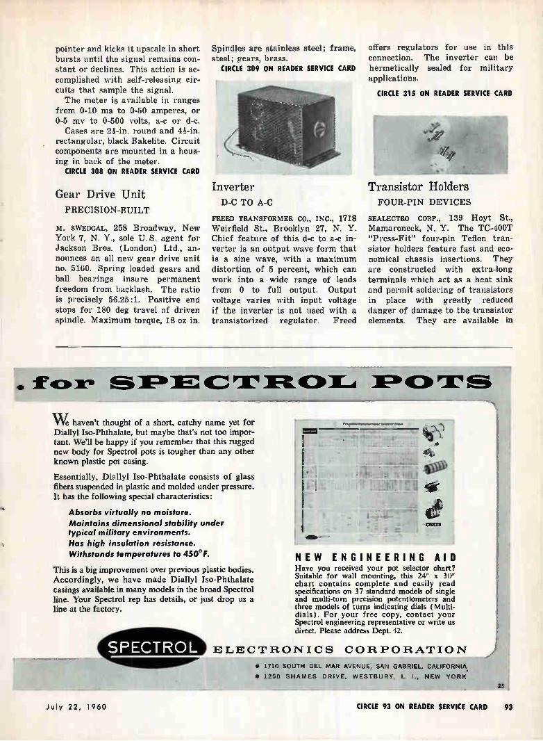
pointer and kicks it upscale in short bursts until the signal remains con-stant or declines. This action is ac-complished with self-releasing cir-cuits that sample the signal. The meter is available in ranges
from 0-10 ma to 0-50 amperes, or 0-5 mv to 0-500 volts, a-c or d-c.
Cases are 2i-in. round and 44-in. rectangular, black Bakelite. Circuit components are mounted in a hous-ing in back of the meter.
CIRCLE 308 ON READER SERVICE CARD
Gear Drive Unit PRECISION-BUILT
M. SWEDGAL, 258 Broadway, New York 7, N. Y., sole U. S. agent for Jackson Bros. (London) Ltd., an-nounces an all new gear drive unit no. 5160. Spring loaded gears and ball bearings insure permanent freedom from backlash. The ratio is precisely 56.25:1. Positive end stops for 180 deg travel of driven spindle. Maximum torque, 18 oz in.
Spindles are stainless steel; frame, steel: gears, brass.
CIRCLE 309 ON READER SERVICE CARD
Inverter D-C TO A-C
FREED TRANSFORMER CO., INC., 1718 Weirfleld St., Brooklyn 27, N. Y. Chief feature of this d-e to a-c in-verter is an output wave form that is a sine wave, with a maximum distortion of 5 percent, which can work into a wide range of leads from 0 to full output. Output voltage varies with input voltage if the inverter is not used with a transistorized regulator. Freed
offers regulators for use in this connection. The inverter can be hermetically sealed for military applications.
CIRCLE 315 ON READER SERVICE CARD
Transistor Holders FOUR-PIN DEVICES
SEALECTRO CORP., 139 Hoyt St., Mamaroneck, N. Y. The TC-400T "Press-Fit" four-pin Teflon tran-sistor holders feature fast and eco-nomical chassis insertions. They are constructed with extra-long terminals which act as a heat sink and permit soldering of transistors in place with greatly reduced danger of damage to the transistor elements. They are available in
ID fox. SX:11 IFE.C,ZA
W haven't thought of a short, catchy name yet for Diallyl Iso-Phthalate, but maybe that's not too impor-tant. We'll be happy if you remember that this rugged new body for Spectrol pots is tougher than any other known plastic pot casing.
Essentially, Diallyl Iso-Phthalate consists of glass fibers suspended in plastic and molded under pressure. It has the following special characteristics:
Absorbs virtually no moisture. Maintains dimensional stability under typical military environments. Has high insulation resistance. Withstands temperatures to 4 5 0°F.
This is a big improvement over previous plastic bodies. Accordingly, we have made Diallyl Iso-Phthalate casings available in many models in the broad Spectrol line. Your Spectrol rep has details, or just drop us a line at the factory.
«RP
Flit:»Tffl
NEW ENGINEERING AID Have you received your pot selector chart? Suitable for wall mounting, this 24" x 30" chart contains complete and easily read specifications on 37 standard models of single and multi-turn precision potentiometers and three models of turns indicating dials ( Multi-dials). For your free copy, contact your Spectrol engineering representative or write us direct. Please address Dept. 42.
ELECTRONICS CORPORATION
• 1710 SOUTH DEL MAR AVENUE, SAN GABRIEL, CALIFORNIA
• 1250 SHAMES DRIVE, WESTBURY, L. I., NEW YORK.
25
July 22, 1960 CIRCLE 93 ON READER SERVICE CARD 93
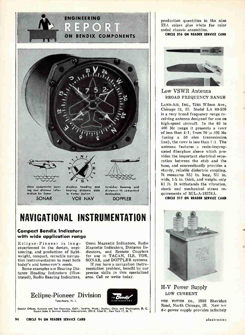
ENGINE RING
ON BENDIX COMPONENTS
show underwater bear-ing and distance infor-mation for Sonar
SONAR
N
E
s
furnishes bearing and distance to computed destination
displays heading and bearing distance data to Vortac Station
VOR NAV DOPPLER
NAVIGATIONAL INSTRUMENTATION Compact Bendix Indicators with wide application range
Eclipse-Pioneer is long-experienced in the design, engi-neering, and production of light-weight, compact, versatile naviga-tion instrumentation to meet both today's and tomorrow's needs. Some examples are Bearing Dis-
tance Heading Indicators (illus-trated), Radio Bearing Indicators,
Omni Magnetic Indicators, Radio Magnetic Indicators, Distance In-dicators, and Remote Couplers for use in TACAN, ILS, VOR, SONAR, and DOPPLER systems.
If you have a navigation instru-mentation problem, benefit by our precise skills in this specialized area. Call or write today.
Eclipse-Pioneer Division Teterboro, N. J.
TIC
ee u
District Offices: Burbank and Son Francisco, Colif. ; Seattle, Wash. ; Dayton, Ohio ; and Washington, D. C. Export Sales & Service: Bendix International, 205 E. 42nd St., New York 17, N. Y.
production quantities in the nine EIA colors plus white for color coded chassis assemblies.
CIRCLE 316 ON READER SERVICE CARD
Low VSWR Antenna BROAD FREQUENCY RANGE
LAND-A1R, INC., 7444 Wilson Ave., Chicago 31, Ill. Model LA 80-320 is a very broad frequency range re-ceiving antenna designed for use on high-speed aircraft. In the 80 to 400 Mc range it presents a vswr of less than 4:1; from 70 to .120 Me (using a 50 ohm transmission line), the vswr is less than 7:1. The antenna features a resin-impreg-nated fiberglass sleeve which pro-vides the important electrical sepa-ration between the stub and the base, and concomitantly provides a sturdy, reliable dielectric coupling. It measures 35).- in. long, 51à in. wide, 1 ?« in. thick, and weighs only 81 lb. It withstands the vibration, shock and mechanical stress re-quirements of MIL-A-1'7(l\.
CIRCLE 317 ON READER SERVICE CARD
H-V Power Supply LOW CURRENT
THE POTTER CO., 1950 Sheridan Road, North Chicago, Ill. New h-v d-c power supply provides infinitely
94 CIRCLE 94 ON READER SERVICE CARD electronics
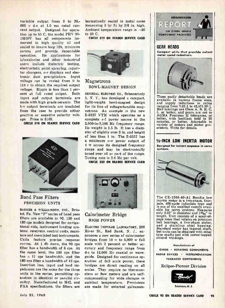
variable output from 0 to 30,-000 y d-c at 1.0 ma rated cur-rent output. Designed for opera-tion up to 85 C, the model PHV 30-1M6OV has all components im-mersed in high quality oil and sealed to insure long life, minimize corona and provide dependable operation. Its applications for laboratories and other industrial users include dielectric testing, electrostatic paint spraying, capaci-tor chargers, c-r displays and elec-tronic dust precipitators. Input voltage can be varied from 0 to 118 y to obtain the required output voltage. Ripple is less than 1 per-cent at full rated output. Both input and output terminals are made with high grade ceramic. The h-v output terminals are insulated from the case to provide either positive or negative polarity volt-age. Price is $169.
CIRCLE 318 ON READER SERVICE CARD
xagî-:"""'-'111111 Band Pass Filters PRECISION UNITS
BARKER & WILLIAMSON, INC., Bris-tol, Pa. New "F" series of band pass filters are available in 90, 150 and 180 cps models designed for naviga-tional aids, instrument landing sys-tems, receivers, control units, moni-tors and associated test instruments. Units feature precise response curves. At 1 db down, the 90 cps filter has a bandwidth of 8 cps. At the same level, the 150 cps filter has a 11 cps bandwidth, and the 180 cps filter a bandwidth of 12 cps. Insertion loss, input and load im-pedances are the same for the three units in the series, permitting op-eration in identical or parallel cir-cuitry. Manufactured to MIL and FAA specifications, the filters are
hermetically sealed in metal cases measuring 3 by 3i by 341 in. high. Ambient temperature range is —20 to 60 C.
CIRCLE 319 ON READER SERVICE CARD
Magnetrons BOWL-MAGNET DESIGN
GENERAL ELECTRIC CO., Schenectady 5, N. Y., has developed a compact, light-weight bowl-magnet design for its line of voltage-tunable mag-netrons. An example is the new Z-5337 VTM which operates as a complete r-f power source in the 2,900-to-3,100 Mc frequency range. Its weight is 1.5 lb. It has a diam-eter of slightly over 3 in. and height of less than 1 in. The Z-5337 has a minimum c-w power output of 4 w across its designed frequency range and may be electronically tuned over all or part of the range. Tuning rate is 2.6 Me per volt.
CIRCLE 320 ON READER SERVICE CARD
Calorimeter Bridge HIGH POWER
ELECTRO IMPULSE LABORATORY, 208 River St., Red Bank, N. J., an-nounces a new series of calorimeter bridges from 10 w to 5,000 w full scale with 2 percent or better ac-curacy and frequency range from d-c to 12,000 Mc coaxial or wave-guide. Designed for continuous op-eration at full scale power, these bridges are direct reading on all scales. They require no thermom-eters or flow meters and are self-compensating for wide changes in. ambient temperature. Provisions are made for external gaivanom-
ENOMEERING .. 1 , ,
ON OTHER BENDIX
COMPONENT PACKAGES
GEAR HEADS Compact units that provide output motor speed reductions.
These easily detachable heads are available in various frame sizes, and supply reductions in ratios ranging from 7.22:1 to 42,471.90:1. Ball bearings are Class A. B. E. C. 5, or better, and gears are cut to AGMA Precision II tolerances, or better, with backlash held to 30 minutes, or better. Adaptable to variety of motors and motor gen-erators. Write for details.
lb-INCH LOW INERTIA MOTOR Designed for instant response in servo systems.
The CK-1066-40-Al Bendix low inertia motor is a two-phase, four-pole, 400-cycle induction type and is one of the smallest motors avail-able for servo systems. Measures only 0.50" in diameter and 11%4" in length. Unit consists of a squirrel-cage rotor that rotates on precision ball bearings, a two-phase stator, and a stainless steel housing. Standard motor has tapered shaft, but units can be obtained with other type shafts and with center-tapped control windings.
Manufacturers of
GYROS • ROTATING COMPONENTS
RADAR DEVICES • INSTRUMENTATION
PACKAGED COMPONENTS
Eclipse-Pioneer Division
imenwee CORPORATIO 11
Teterboro, N. J.
July 22, 1960 CIRCLE 95 ON READER SERVICE CARD 95
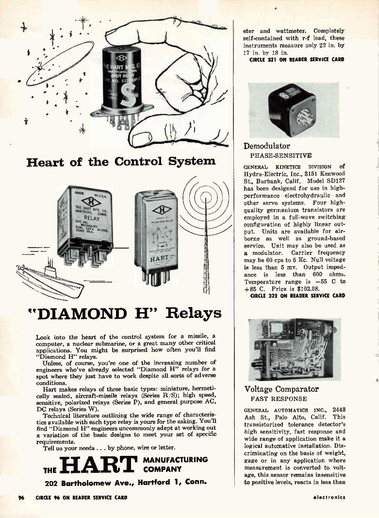
Heart of the Control System
"DIAMOND H" Relays
Look into the heart of the control system for a missile, a computer, a nuclear submarine, or a great many other critical applications. You might be surprised how often you'll find "Diamond H" relays.
Unless, of course, you're one of the increasing number of engineers who've already selected "Diamond H" relays for a spot where they just have to work despite all sorts of adverse conditions. Hart makes relays of three basic types: miniature, hermeti-
cally sealed, aircraft-missile relays (Series R/S); high speed, sensitive, polarized relays (Series P), and general purpose AC, DC relays (Series W).
Technical literature outlining the wide range of characteris-tics available with each type relay is yours for the asking. You'll find "Diamond H" engineers uncommonly adept at working out a variation of the basic designs to meet your set of specific requirements.
Tell us your needs . . . by phone, wire or letter.
THE HART MANUFACTURING COMPANY
202 Bartholomew Ave., Hartford 1, Conn.
eter and wattmeter. Completely self-contained with r-f load, these instruments measure only 22 in. by 17 in. by 18 in.
CIRCLE 321 ON READER SERVICE CARD
Demodulator PHASE-SENSITIVE
GENERAL KINETICS sIvisIoN of Hydra-Electric, Inc., 3151 Kenwood St., Burbank, Calif. Model SD127 has been designed for use in high-performance electrohydraulic and other servo systems. Four high-quality germanium transistors are employed in a full-wave switching configuration of highly linear out-put. Units are available for air-borne as well as ground-based service. Unit may also be used as a modulator. Carrier frequency may be 60 cps to 5 Kc. Null voltage is less than 5 mv. Output imped-ance is less than 600 ohms. Temperature range is —55 C to +85 C. Price is $102.98.
CIRCLE 322 ON READER SERVICE CARD
Voltage Comparator FAST RESPONSE
GENERAL AUTOMATICS INC., 2443 Ash St., Palo Alto, Calif. This transistorized tolerance detector's high sensitivity, fast response and wide range of application make it a logical automative installation. Dis-criminating on the basis of weight, gage or in any application where measurement is converted to volt-age, this sensor remains insensitive to positive levels, reacts in less than
96 CIRCLE 96 ON READER SERVICE CARD electronics
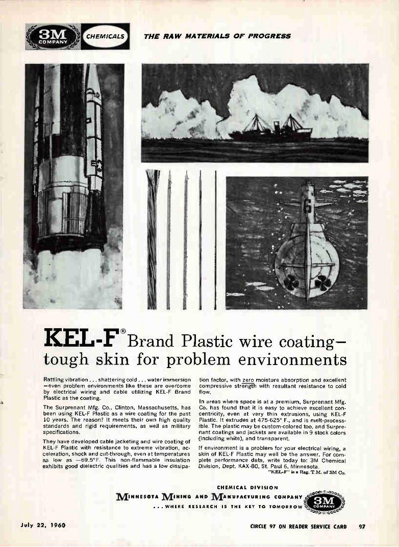
THE RAW MATERIALS OF PROGRESS
KEL-F u Brand Plastic wire coating— tough skin for problem environments Rattling vibration ... shattering cold ... water immersion —even problem environments like these are overcome by electrical wiring and cable utilizing KEL-F Brand Plastic as the coating.
The Surprenant Mfg. Co., Clinton, Massachusetts, has been using KEL-F Plastic as a wire coating for the past 10 years. The reason? It meets their own high quality standards and rigid requirements, as well as military specifications.
They have developed cable jacketing and wire coating of KEL-F Plastic with resistance to extreme vibration, ac-celeration, shock and cut-through, even at temperatures as low as —69.5°F. This non-flammable insulation exhibits good dielectric qualities and has a low dissipa-
tion factor, with zero moisture absorption and excellent compressive strerrt h with resultant resistance to cold flow.
In areas where space is at a premium, Surprenant Mfg. Co. has found that it is easy to achieve excellent con-centricity, even at very thin extrusions, using KEL-F Plastic. It extrudes at 475-625° F., and is melt-process-ible. The plastic may be custom-colored too, and Surpre-nant coatings and jackets are available in 9 stock colors (including white), and transparent.
If environment is a problem for your electrical wiring, a skin of KEL-F Plastic may well be the answer. For com-plete performance data, write today to: 3M Chemical Division, Dept. KAX-80, St. Paul 6, Minnesota.
"KEL-F" a Reg- T.M. of 3M Co.
CHEMICAL DIVISION M INNESOTA M INING AND M ANUFACTURING COMPANY
...WHERE RESEARCH IS THE KEY TO TOMORROW% COMPANY
July 22, 1960 CIRCLE 97 ON READER SERVICE CARD 97
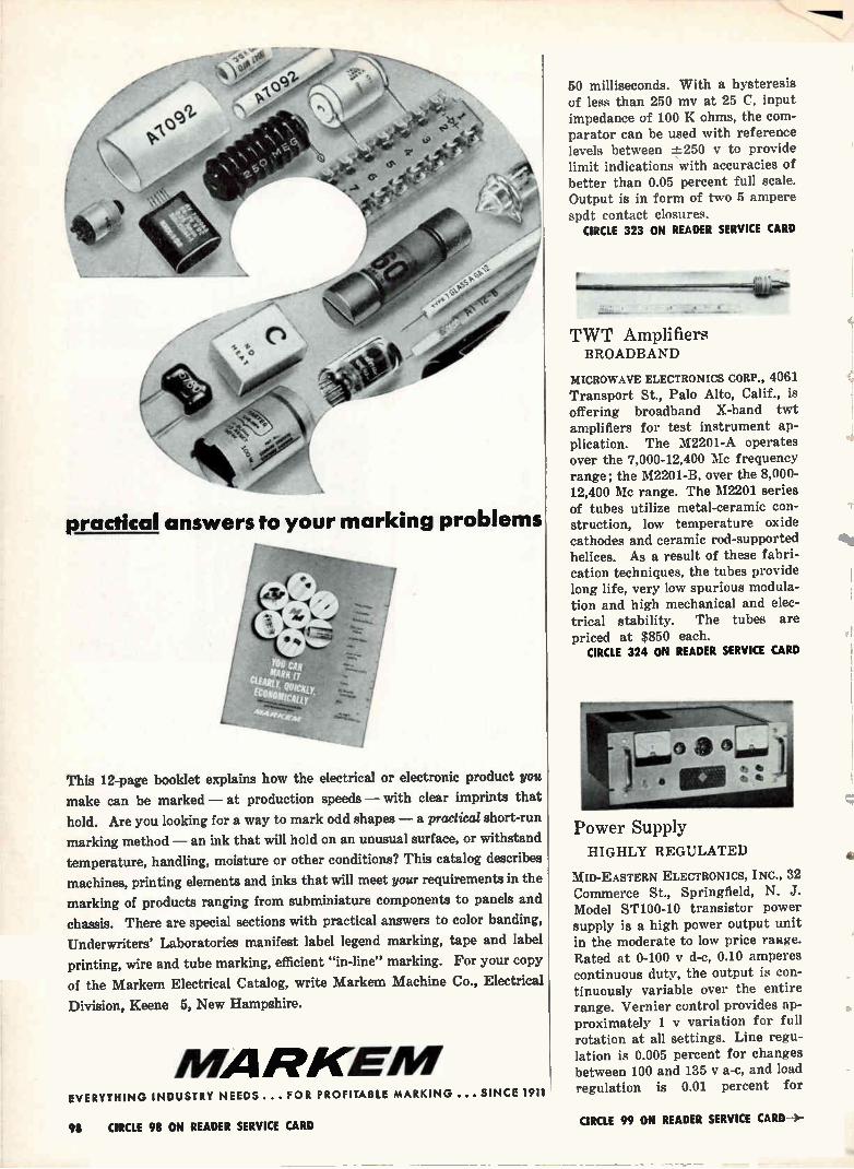
practical answers to your marking problems
7 4 ,
• /4 4.Zir
A Au
,•14,„,- • e.
4 4càtilit4i.7 Pe
This 12-page booklet explains how the electrical or electronic product you
make can be marked — at production speeds — with clear imprints that
hold. Are you looking for a way to mark odd shapes — a practical short-run
marking method — an ink that will hold on an unusual surface, or withstand
temperature, handling, moisture or other conditions? This catalog describes
machinas, printing elements and inks that will meet your requirements in the
marking of products ranging from subminiature components to panels and
chassis. There are special sections with practical answers to color banding,
Underwriters' Laboratories manifest label legend marking, tape and label
printing, wire and tube marking, efficient "in-line" marking. For your copy
of the Markem Electrical Catalog, write Markem Machine Co., Electrical
Division, Keene 5, New Hampshire.
MARKEN/ EVERYTHING INDUSTRY NEEDS ... FOR PROFITABLE MARKING ... SINCE 1911
50 milliseconds. With a hysteresis of less than 250 my at 25 C, input impedance of 100 K ohms, the com-parator can be used with reference levels between -_L-250 v to provide limit indications with accuracies of better than 0.05 percent full scale. Output is in form of two 5 ampere spdt contact closures.
CIRCLE 323 ON READER SERVICE CARD
TWT Amplifiers BROADBAND
MICROWAVE ELECTRONICS CORP., 4061 Transport St., Palo Alto, Calif., is offering broadband X-band twt amplifiers for test instrument ap-plication. The M2201-A operates over the 7,000-12,400 Mc frequency range; the M2201-B, over the 8,000-12,400 Mc range. The M2201 series of tubes utilize metal-ceramic con-struction, low temperature oxide cathodes and ceramic rod-supported helices. As a result of these fabri-cation techniques, the tubes provide long life, very low spurious modula-tion and high mechanical and elec-trical stability. The tubes are priced at $850 each.
CIRCLE 324 ON READER SERVICE CARD
Power Supply HIGHLY REGULATED
MID-EASTERN ELECTRONICS, INC., 32 Commerce St., Springfield, N. J. Model ST100-10 transistor power supply is a high power output unit in the moderate to low price range. Rated at 0-100 y d-c, 0.10 amperes continuous duty, the output is con-tinuously variable over the entire range. Vernier control provides ap-proximately 1 y variation for full rotation at all settings. Line regu-lation is 0.005 percent for changes between 100 and 135 V a-c, and load regulation is 0.01 percent for
98 CIRCLE 98 ON READER SERVICE CARD CIRCLE 99 ON READER SERVICE CARD-4.-
TIME means both money and reputation to
system builders. To help .customers save
both, over 10,200 klystron and traveling
wave tubes have been shipped ON TIME
from Sperry's Gainesville, Florida plant. If
prompt tube delivery is vital to your system,
call Gainesville, FRanklin 2-0411 collect, for
full information about Sperry capabilities.
si[1111Y IL ELECTRONIC
r TUBE
DIVISION
Gainesville, Florida • A Division
SPERRY'S FAMILY OF TRAVELING WAVE TUBES covers P through X Bands with unusu-ally high output and light weight. These charac-teristics, combined with the inherent ruggedness of metal-ceramic construction, conduction cooling and wide-range thermal compensation, make Sperry traveling wave tubes particularly suitable for airborne applications.
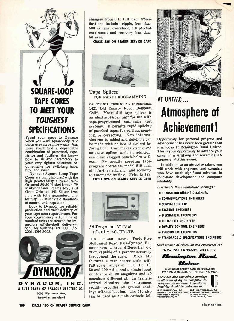
\NM
SQUARE-LOOP TAPE CORES
TO MEET YOUR TOUGHEST
SPECIFICATIONS Speed your specs to Dynacor when you want square-loop tape cores to exact requirements—fast! Here you'll find a dependable combination of personnel, expe-rience and facilities—the know-how to deliver parameters to your very tightest tolerance re-quirements for switching time, flux, and noise. Dynacor Square-Loop Tape
Cores are manufactured with the high permeability alloys—Grain-Oriented 50-50 Nickel Iron, 4-79 Molybdenum Permalloy, and Grain-Oriented 3% Silicon Iron . . . with fully guaranteed uni-formity .... under rigid standards of control and inspection. Look to Dynacor for reliable
production and swift delivery of your tape core requirements. For your convenience a full line of standard units are stocked for im-mediate off-the-shelf delivery— Send for bulletins DN 2000, DN 2001, DN 2002.
IDYNACOR DYNACOR, INC. A SUBSIDIARY OF SPRAGUE ELECTRIC CO.
1006 Westmore Ave
Rockville, Maryland
changes from 0 to full load. Speci-fications include: ripple, less than 500 /Ay rms; overshoot, 1.0 percent maximum; and recovery less than 50 ilsec.
CIRCLE 325 ON READER SERVICE CARD
Tape Splicer FOR FAST PROGRAMMING
CALIFORNIA TECHNICAL INDUSTRIES,
1421 Old County Road, Belmont, Calif. Model 219 tape splicer is an ideal accessory unit for use with tape-programmed automatic test systems. It permits rapid splicing of punched tapes for editing, mend-ing, or correcting. New informa-tion can be added and deletions can be made with no loss of desired in-formation. Unit makes strong and accurate splices and, in addition, can clean clogged punch-holes with ease. By greatly speeding tape-program operation, model 219 adds still further efficiency and economy to automatic testing. Price is $28.
CIRCLE 326 ON READER SERVICE CARD
Differential VTVM HIGHLY ACCURATE
THE DECKER CORP., Forty-Five Monument Road, Bala-Cynwyd, Pa., announces a true differential d-c vtvm capable of 1 percent accuracy throughout the scale. Model 410 features a zero center scale with full scale ranges of -±-0.3, 1.0, 10, 30 and 100 y d-c, and a single input impedance of 20 megohms and 40 megohms differential. In transis-torized circuitry the instrument readily provides off ground read-ings without loading. The 410 also can be used as a unit cathode fol-
AT UNIVAC
Atmosphere of Achievement!
Opportunity for personal progress and advancement has never been greater than it is today at Remington Rand Univac. This is your opportunity to advance your career in a satisfying and rewarding At-mosphere of Achievement.
In addition to an attractive salary, you will work with engineers and scientists who have made significant advances in solid-state development and computer reliability.
Investigate these immediate openings:
• TRANSISTOR CIRCUIT DESIGNERS
um COMMUNICATIONS ENGINEERS
• SERVO-ENGINEERS
• SYSTEMS ENGINEERS
• MECHANICAL ENGINEERS
• RELIABILITY ENGINEERS
• QUALITY CONTROL ENGINEERS
• PRODUCTION ENGINEERS
• STANDARDS & SPECIFICATIONS ENGINEERS
Send resume of education and experience to:
R. K. PATTERSON, Dept. T-7
HPirni:a4rtim
iirmisere_ DIVISION OF SPERRY RAND CORPORATION
2750 West Seventh St., St. Paul 16, Minn.
There are also immediate openings in all areas of digital computer de-velopment at our other laboratories. Inquiries should be addressed to: F. E. NAGLE.Dept. T-7 R. F. MARTIN. Dept. T-7 REMINGTON RAND UNIVAC REMINGTON RAND UNIVAC 1900 West Allegheny Wilson Avenue Philadelphia 29, Pa. South Norwalk, Conn.
100 CIRCLE 100 ON READER SERVICE CARD electronics
NEED PRODUCT INFO? LOOK IN THE NEW
electronics BUYERS' GUIDE You'll find detailed facts about the products of
almost 700 different advertisers — that's 42% more
than you'll find in any other electronics directory.
There's also 64 pages of reference data about mar-
kets, materials and design — vital information for all
working in electronics. Also local sales offices of man-
ufacturers . . . the names, addresses and phone num-
bers of representatives . . . complete lists of manu-
facturers . . . registered trade names . . . and also, of
course, the most complete listing of all electronic and
related products. Tells what you want to know ...
when you're ready to buy.
fi A McGraw-Hill Publication • 330 West 42nd Street. Now York 36. New York
July 22, 19 60 101
Special Sockets and Connectors
àtettlie ®
e FROM DESIGN
TO PRODUCTION Jettron is fully-equipped to design and manufacture your precision electronic components including connectors, sockets and cable assemblies. Call or write Jettron for quotations on "specials" for all commercial and military applications.
CD-7140 — Printboard Application Socket for R.C.A. Micromodule. Measures only .400 maximum square by .094 high. Insulation resistance greater than 50,000 megohms. Employs silver plated beryllium copper con-tacts and WALL FS-5 insulating material.
CAT. 8550—Ultra High Frequency Socket for the G.E. GL-629 9 Triode is sold in kit form containing all the necessary parts for mounting by the customer on a chassis barrier. It provides excellent isolation of the input from the output.
CAT. 8715—Ultra-High Temperature Socket for G.E. 7296 Triode can be soldered to printboard or mounted above or below a chassis. High Alumina insulating material; contacts gold plated Inconel -X. For continu-ous operation at 1000 F (538' C).
J E TT R 0 N PRODUCTS • INC 56 Route 10, Hanover, New Jersey Telephones: TUcker 7-0571-0572
Sales Engineers in Principal Cities
lower, having an open circuit gain of 0.85 which can be varied in defi-nite steps by the input divider maintaining the input impedance with an output impedance of 1,000 ohms.
CIRCLE 327 ON READER SERVICE CARD
Planetary Ball Drive PRECISION-BUILT
M. SWEDGAL, 258 Broadway, New York, N. Y., sole U. S. agent foi Jackson Bros. (London) Ltd., an-nounces a new planetary ball drive No. 4511/DAF. Simple and power-ful epicyclic friction drive. Ball bearings. Ratio 6-1. Dimensions 1.% in. diameter, Ils in. long, plus 1i in. shaft. 15-20 oz in.
CIRCLE 328 ON READER SERVICE CARD
D-C Power Supply FOR GROUND SUPPORT
PERKIN ENGINEERING CORP., 345 Kansas St., El Segundo, Calif., an-nounces model M-1216-1 d-c power supply with an output of 22-33 I/ at 50 amperes for aircraft ground support. The compact (8 by 16 by 10 in.) supply has an efficiency of 70 percent at 28 y and 25 to 50 amperes. All-static and reactor-controlled, it maintains its d-c out-put at from 22 to 33 v, no load to full load, on an input of 220/440 nominal +10 percent, —15 percent, 3-phase, 60 cps -±-5 percent. Ripple is less than 5 percent rms. Well suited for such applications as operating aircraft relays in test
OPENINGS IN Systems Analysis
Design & Development Evaluation
Systems Analysis Weapons Systems analysts with BS or MS in mathematics or physics, or BSEE, to work on weapons system and component lethality, evaluations, optimiza-tion studies, feasibility studies, and concept synthesis. Also a BSEE or MSEE with a minimum of 3 years in electronic systems with emphasis on remote control, data handling, signal processing.
Design and Development A number of openings now exist for experienced design and devel-opment engineers with the fol-lowing qualifications: BSEE or MSEE, minimum 3
years experience in any of these fields: Solid state circuit design, including amplifiers and switch-ing circuitry; RF techniques, in-cluding circuit design; antenna design, propagation studies, modulation techniques. Signal processing and data handling, in-cluding techniques for encoding, decoding,- storage, digital data processing, display, system inte-gration. Also: openings for BSEE with minimum one year in syn-thesis servo analysis or servo application.
Evaluation BSEE. Prefer 1-8 years in test, design, or related areas. Work in-volves testing specific unit sys-tems, parts, or materials. May involve designing and building non-standard testing equipment; field or simulated field testing; tests on production instruments. All above openings are in Minne-apolis area. For complete informa-tion, 'write Allan J. McInnis, Pro-fessional Manpower Staff, Ord-nance Division, Honeywell, 600 Second St. North, Hopkins, Minn.
Honeywell
To explore professional opportunities in other Honeywell operations, coast to coast, send your application in con-fidence to H. D. Eckstrom, Honeywell, Minneapolis 8, Minn.
102 CIRCLE 102 ON READER SERVICE CARD electronics
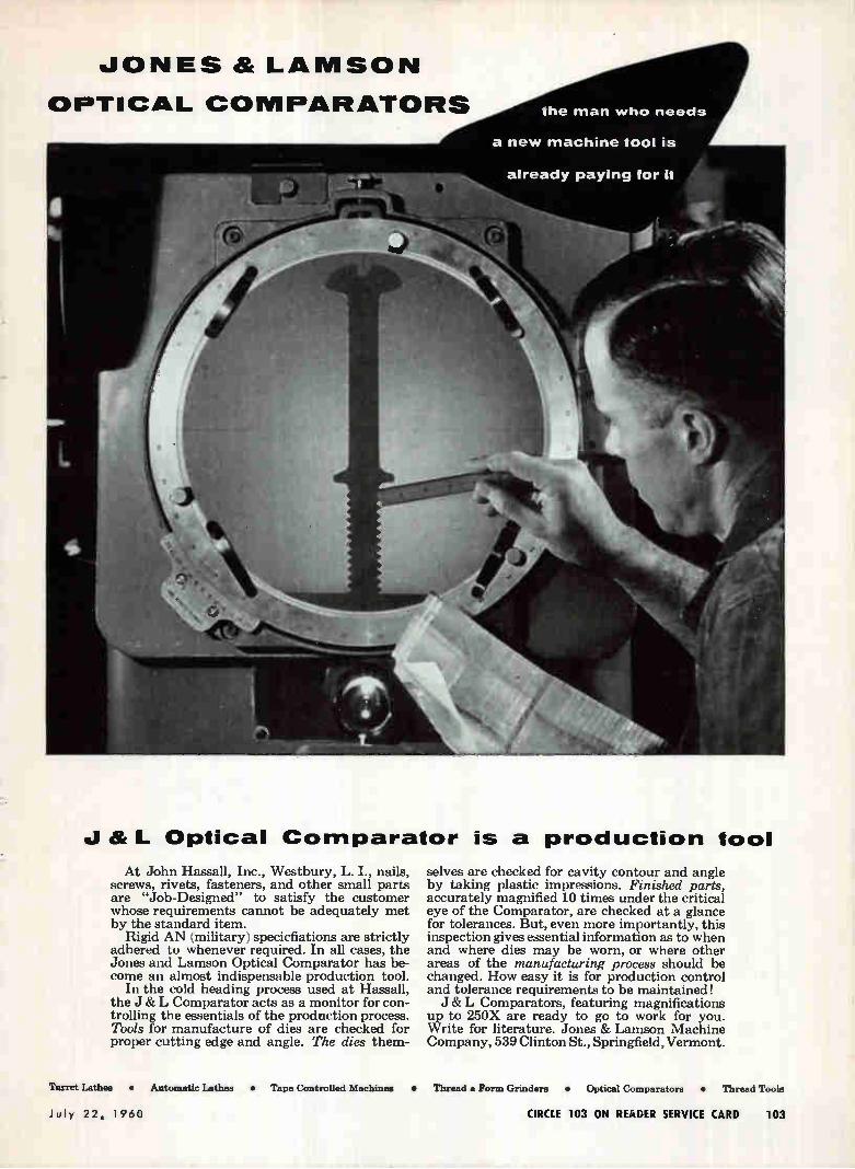
JONES & LAMSON
OPTICAL COMPARATORS
At John Hassall, Inc., Westbury, L. I., nails, screws, rivets, fasteners, and other small parta are "Job-Designed" to satisfy the customer whose requirements cannot be adequately met by the standard item.
Rigid AN (military) specicfiations are strictly adhered to whenever required. In all cases, the Jones and Lamson Optical Comparator has be-come an almost indispensable production tool.
In the cold heading process used at Hassall, the J & L Comparator acts as a monitor for con-trolling the essentials of the production process. Tools for manufacture of dies are checked for proper cutting edge and angle. The dies them-
Turret Lathes •
J & L Optical Comparator is a production tool
selves are checked for cavity contour and angle by taking plastic impressions. Finished parts, accurately magnified 10 times under the critical eye of the Comparator, are checked at a glance for tolerances. But, even more importantly, this inspection gives essential information as to when and where dies may be worn, or where other areas of the manufacturing process should be changed. How easy it is for production control and tolerance requirements to be maintained! J & L Comparators, featuring magnifications
up to 250X are ready to go to work for you. Write for literature. Jones & Lamson Machine Company, 539 Clinton St., Springfield, Vermont.
Automatic Lathes • Tape Controlled Machines • Thread & Form Grinders • Optical Comparators • Thread Toole
July 22. 1960 CIRCLE 103 ON READER SERVICE CARD 103
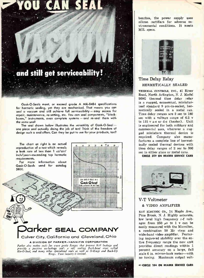
s.
Gask-O-Seals meet, or exceed grade A MIL-8484 specifications for hermetic sealing, yet they are mechanical. That means you can seal a vacuum and still achieve full serviceability — easy access for repair, maintenance, re-setting, etc. You can seal components, "black-boxes," instruments, even complete systems — and re-seal them with the some seal!
The seal shown below illustrates the versatility of Gask-O-Seal — one piece seal actually doing the job of ten! Think of the freedom of design such a seal offers. Can they be put to use for your products, too?
The chart at right is an actual reproduction of a test which reveals a leak rate of less than 1 cc/air/ inch/year—exceeding top hermetic requirements.
For more information about Gask-O-Seals send for catalog 5800.
PCulver City, California and Cleveland, Ohio
I
LEM RAlf OF B3I8.7 IN A
Cask OSeal cenhmeters Ya1.ch Year
11-114-
f , ..
a rker SEAL COM PANY
A DIVISION OF PARKER-HANNIFIN CORPORATION
Parker also makes seals for wave guide flanges that prez en; R/F leakage and provide a positive no-leakage seal; a self sealing flush-head rivet called Riv-O-Seal, and many other specialized seals as well as 0-Rings and Back-UP
Rings. Your inquir) if invited.
benches, the power supply uses silicon rectifiers for adverse en-vironmental conditions. It meets MIL specs.
Time Delay Relay HERMETICALLY SEALED
THERMAL CONTROLS, INC., 41 River Road, North Arlington, N. J. Model 900G thermal time delay relay is a rugged, economical, miniatur-ized standard 9 pin-in-socket, her-metically sealed in a metal can. Time delay ranges are 2 sec to 180 sec with a voltage range of 6.3 to 115 y a-c or d-c (heater). Unit is engineered for both military and commercial uses, wherever a rug-ged miniature thermal device is required. Company also manu-factures a complete line of hermet-ically sealed thermal devices with time delay ranges of 2 sec to 300 sec in either glass or metal cans.
CIRCLE 329 ON READER SERVICE CARD
V-T Voltmeter & VIDEO AMPLIFIER
KAY ELECTRIC CO., 14 Maple Ave., Pine Brook, N. J. Highly accurate, low level high frequency r-f volt-ages from 250 gy to 1 y can be easily measured with the Microlter, a combination 50 Mc ytym and wide-band video amplifier. Featur-ing improved stability over the en-tire frequency range the new unit provides direct readings within 1 percent accuracy on a large, full scale 6 in. mirror-back meter—with no tuning. Maximum output volt-
-‹—CIRCLE 104 ON READER SERVICE CARD
age of video amplifier is 0.5 y at 75 ohms with an amplifier gain of 45 db. Operating range of the Microlter is from 50 cps to 50 Mc with direct readings in volts and decibels.
CIRCLE 330 ON READER SERVICE CARD
Resistors LOW INDUCTANCE
GB COMPONENTS, INC., 14621 Ar-minta St., Van Nuys, Calif., an-nounces a new line of low reactance resistors in the total resistance ranges of its present high precision encapsulated wirewound product lines. Company says this develop-ment is a major breakthrough in making available to the industry an extremely accurate resistance prod-uct without the undesirable char-acteristics of high distributed ca-pacitance and objectionable levels of electrical inductance.
CIRCLE 331 ON READER SERVICE CARD
Variable Delay Line VERY SMALL SIZE
JFD ELECTRONICS CORP., 6101 Six-teenth Ave., Brooklyn, N. Y. Espe-cially suited for p-c board applica-tions, this delay line provides a high ratio of delay to rise time in minimum space. The high imped-ance variable tap provides ex-tremely fine resolution per turn. Provision is made for locking shaft in any position. Other characteris-tics provided are: exceptional rug-gedness, precise pulse fidelity, —55 C to +125 C operating temperature range, high resistance to environ-mental conditions, such as moisture, humidity, shock and vibration. It features 0.1 in. grid spacing for p-c mounting, approximately 1 db per ¿sec attenuation, extremely
ADVANCED ENGINEERING
PRECISION FABRICATION
to convert your antenna concepts
into reliable structures. For information, contact the Blaw-Knox Equipment Division, Pittsburgh 38, Pa.
21.11 WarICIAIIOX ANTENNAS
July 22, 1960 CIRCLE 107 ON READER SERVICE CARD 107
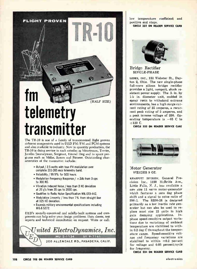
FLIGHT PROVEN
fm telemetry transmitter
IMO
40,
The TR-10 is one of a family of transistorized flight proven airborne components used in UED FM/FM and PCM systems and also available to industry. Now in quantity production, the TR-10 is doing service in such missiles as Minuteman, Terrier, Javelin/Journeyman, Sergeant, Hound Dog and in space pro-grams such as Midas, Samos and Pioneer. Outstanding char-acteristics of the transmitter include:
• Output / 2.5 watts with true FM modulation over complete 215-265 mcs telemetry band. • Reliability / 99.9% for 500 hours.
• Modulation Frequency Response / ±2db from 3 cps to 300 KC. • Vibration Induced Noise / less than 3 KC deviation
at 20 g's from 20 cps to 2000 cps. • Qualifies to Radio Noise Specification MIL-STD-442. • Modulation Linearity / less than 1% from straight line
at 125 KC deviation. • Exceeds military environmental specifications including
MIL-E-5272.
UED's soundly-conceived and solidly-built systems and com-ponents can help solve your design problems. Data sheets, test reports and technical consultation on request. Write or call:
United ElectroDynamics, Inc. ED MU 2- 1 1 34 SY 9-7161
200 ALLEN DALE RD., PASADENA, CALIF.
low temperature coefficient and positive end stops.
CIRCLE 332 ON READER SERVICE CARD
•
Bridge Rectifier SINGLE-PHASE
LEDEX, INC., 123 Webster St., Day-ton 2, Ohio. The new single-phase full-wave silicon bridge rectifier provides a light, compact, shock re-sistant power supply. The es in. by lie in. diameter unit, molded in epoxy resin to withstand extreme environments, has a high surge cur-rent rating of 35 amperes, a recur-rent peak rating of 5 amperes, and a peak inverse voltage of 200. Op-erating temperature is —65 C to +120 C.
CIRCLE 333 ON READER SERVICE CARE
Motor Generator WEIGHS 9 OZ.
KEARFOTT DIVISION, General Pre-cision Inc., 1150 McBride Ave., Little Falls, N. J., has available a new size 11 servo motor-generator which features a zero deg phase shift and a signal to noise ratio of 290:1. The R830-26 is designed primarily as a low inertia rate gen-erator but can also be used to re-place most size 15 units in high gain damping applications. In-phase speed-sensitive output varia-tions due to variations of ambient temperature are stabilized to with-in 0.2 deg C throughout the temper-ature range. Speed-sensitive volt-age and frequency variations are stabilized to within -±-0.2 percent for voltage and 0.03 percent/cycle for frequency.
CIRCLE 334 ON READER SERVICE CARD
108 CIRCLE 108 ON READER SERVICE CARD electronics
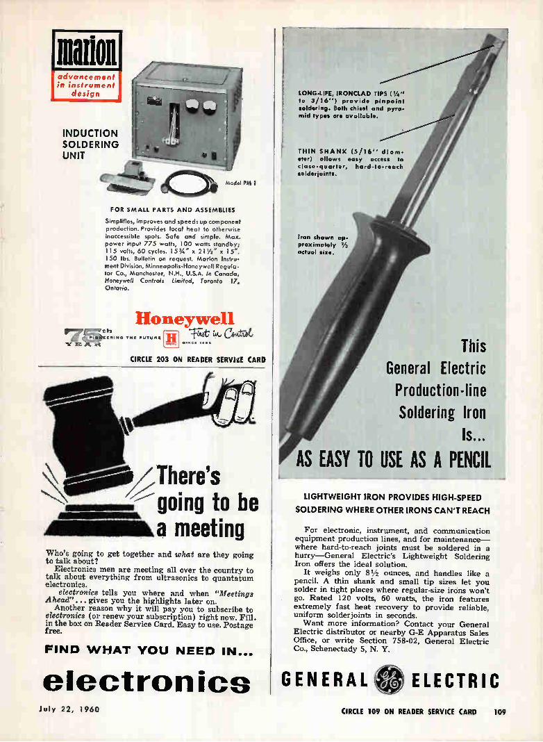
111.","1"7 " 'ela è...4 .10EERIN• Tlit FUTURE
•hr 1E Pk 1-C
1111111.e
111111011 advancement in instrument
design
INDUCTION SOLDERING UNIT
/
Model PM I
FOR SMALL PARTS AND ASSEMBLIES
Simplifies, improves and speeds up component production. Provides local heat to otherwise inaccessible spots. Safe and simple. Max. power input 775 watts, 100 watts standby; 115 volts, 60 cycles. 15 3/4 " x 21 1/2 " x 15". 150 lbs. Bulletin on request. Marion Instru-ment Division, Minneapolis-Honeywell Regula-tor Co., Manchester, N.H., U.S.A. In Canada, Honeywell Controls Limited, Toronto 17, Ontario.
Honeywell ui-c&ed,
•.»Ct •••• H
CIRCLE 203 ON READER SERVILE CARD
There's going to be meeting
Who's going to get together and what are they going to talk about?
Electronics men are meeting all over the country to talk about everything from ultrasonics to quantatum electronics.
electronics tells you where and when "Meetings Ahead"... gives you the highlights later on.
Another reason why it will pay you to subscribe to electronics (or renew your subscription) right now. Fill. in the box on Reader Service Card. Easy to use. Postage free.
FIND WHAT YOU NEED IN...
electronics
LONG-LIFE, IRONCLAD TIPS ( 1/4 " to 3/16') provide pinpoint soldering. Both chisel and pyra-mid types are available.
THIN SHANK (5/16" diam-eter) allows easy access to close-quarter, hard-to-reach solderjoints.
Iron shown ap-proximately 2/3 actual size.
This General Electric Production-line Soldering Iron
Is...
AS EASY TO USE AS A PENCIL
LIGHTWEIGHT IRON PROVIDES HIGH-SPEED
SOLDERING WHERE OTHER IRONS CAN'T REACH
For electronic, instrument, and communication equipment production lines, and for maintenance— where hard-to-reach joints must be soldered in a hurry—General Electric's Lightweight Soldering Iron offers the ideal solution.
It weighs only 81/2 ounces, and handles like a pencil. A thin shank and small tip sizes let you solder in tight places where regular-size irons won't go. Rated 120 volts, 60 watts, the iron features extremely fast heat recovery to provide reliable, uniform solderjoints in seconds. Want more information? Contact your General
Electric distributor or nearby G-E Apparatus Sales Office, or write Section 758-02, General Electric Co., Schenectady 5, N. Y.
GENERAL ELECTRIC July 22, 1960 CIRCLE 109 ON READER SERVICE CARD 109

AEU Le/ LI"' 1E1 le" MARTA el'41
FOUR OPERATIONAL MISSILES
JD® @C)G3PCDGIL211021 ¢Œ)oba Petie, 1.[LQ oz.
Ne5
S-506-DS Socket with
deep brackets
JONES PLUGS 8t SOCKETS
500 SERIES
PLekteee
2«.4iieef
For 5,000 Volts 25 Amperes per Con-tact Alterable by circuit Character-istics.
Socket contacts phosphor bronze knife-switch type, cadmium plated. Plug contacts hard brass cadmium plated 2, 4, 6, 8, 10, and 12 contacts. Plugs and sockets polar-ized. Long leakage path from terminal, and terminal to ground. Caps and brackets, steel parkerized (rust proofed). Plug and socket blocks interchangeable in caps and brackets. Terminal connections most ac-cessible. Cap insulated with canvas bakelite.
Write for Jones BULLETIN 22
for full details on line.
HOWARD B. JONES DIVISION CINCH NANUF•CTURING CONPANY
CHICAGO 24. ILLINOIS DIVISION OF UNITED-CARS FASIENtS
Literature of CHART DRIVES Insco Co., di-vision of Barry Controls, Hollis St., Groton, Mass., has published a cata-log describing multi-speed chart drives for use with a variety of strip chart recorders.
CIRCLE 350 ON READER SERVICE CARD
TRANSISTOR CHARACTER-ISTICS Derivation And Tabula-tion Associates, 95 Harrison Ave., West Orange, N.J. A new brochure illustrates and describes D.A.T.A.'s transistor characteristics tabula-tion, a comprehensive digest of the world's transistors, completely up-dated twice a year with a supple-ment between complete editions.
CIRCLE 351 ON READER SERVICE CARD
FREQUENCY DISCRIMINATOR Magnetic Research Corp., 3160 West El Segundo Blvd., Hawthorne, Calif., has published an engineer-ing data sheet containing complete details on its 115-v 400 cycle, 0-5 y d-c range frequency discrimina-tor model 91-105-0.
CIRCLE 352 ON READER SERVICE CARD
ELECTROLYTIC CAPACITORS Pyramid Electric Co., Darlington, S. C., has available a four-page engineering bulletin on the type ML subminiature aluminum electro-lytic capacitors.
CIRCLE 353 ON READER SERVICE CARD
MICROPHONES The Astatie
Corp., Conneaut, Ohio. Catalog M10 includes information covering specifications, applications and prices along with charts showing typical response-frequency char-acteristics of the company's micro-phone line. Accessories are also listed.
CIRCLE 354 ON READER SERVICE CARD
TIME DELAYS G-V Controls Inc., 101 Okner Parkway, Livingston, N.J. Technical publication No. 80 describes a new concept of versa-tility in transistorized time delays.
CIRCLE 355 ON READER SERVICE CARD
DATA TRANSLATOR Electronic Engineering Co. of California, 1601 East Chestnut Ave., Santa Ana, Calif. A new data sheet describes the ZA-26965 data translator which
CIRCLE 205 ON READER SERVICE CARD 110 CIRCLE 110 ON READER SERVICE CARD electronics
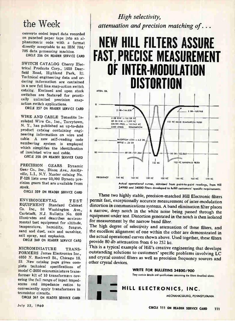
the Week converts coded input data recorded on punched paper tape into an al-phanumeric code with a format directly acceptable to an IBM 704/ 705 data processing machine.
CIRCLE 356 ON READER SERVICE CARD
SWITCH CATALOG Cherry Elec-trical Products Corp., 1650 Deer-field Road, Highland Park, Ill. Technical engineering data and or-dering information are contained in a new full line snap-action switch catalog. Enclosed and open stack switches are featured for practi-cally unlimited precision snap-action switch applications.
CIRCLE 357 ON READER SERVICE CARD
WIRE AND CABLE Tensolite In-sulated Wire Co., Inc., Tarrytown, N. Y., has published an up-to-date product catalog containing engi-neering information on wire and cable. A new self-reading code numbering system is employed which simplifies the identification of insulated wire and cable.
CIRCLE 358 ON READER SERVICE CARD
PRECISION GEARS Dynamic Gear Co., Inc., Dixon Ave., Amity-ville, L.I., N.Y. Master catalog No. F-128 lists over 50,000 Dynaco pre-cision gears that are available from stock.
CIRCLE 359 ON READER SERVICE CARD
ENVIRONMENTAL TEST EQUIPMENT Standard Cabinet Co. Inc., 56 Washington Ave., Carlstadt, N.J. Bulletin No. 60B illustrates and describes environ-mental test equipment for altitude, temperature, humidity, fungus, sand and dust, rain and sunshine, salt spray, and explosion.
CIRCLE 360 ON READER SERVICE CARD
MICROMINIATURE TRANS-FORMERS James Electronics Inc., 4050 N. Rockwell St., Chicago 18, Ill. New catalog page gives com-plete technical specifications of model C-2650 microminiature trans-former kit of 10 transformers cov-
ering the full range of input imped-ances and impedance ratios to conveniently apply transformers in transistor circuits.
CIRCLE 361 ON READER SERVICE CARD
High selectivity,
attenuation and precision matching of . . .
NEW HILL FILTERS ASSURE FAST, PRECISE MEASUREMENT
OF INTER-MODULATION DISTORTION
ATOEN. DB.
20
40
oo
so
2 D8-144.830
2 D8 B.W. = 16.138 KC
80 DB 1.599 KC
CENTER FREQ. 152.063 KC 2400 OHMS TERMINATION
T 1NSERT/ON LOSS = 4.5 D6 RIPPLE = .25 OS
FREQUENCY
SO DS 51.264
140 KC 145 KC 150 KC 155 KC 160 KC 165 KC 170 KC
152 KC 152 KC RANOPASS FRIER
Actual operational curves, obtained from point-to-point readings, from Hill
34900 and 34800 filters developed to fulfill customers specific requirements.
These two highly stable, precision-matched Hill Electronic filters permit fast, exceptionally accurate measurement of inter-modulation distortion in communications systems. A band elimination filter places a narrow, deep notch in the white noise being passed through the equipment under test. Distortion generated in the notch is then isolated for measurement by the narrow band filter. The high degree of selectivity and attenuation of these filters, and the excellent alignment of one within the other are demonstrated in the actual operational curves shown above. Used together, these filters provide 80 db attenuation from 6 to 252 kc. This is a typical example of Hill's creative engineering that develops outstanding solutions to customers' specific problems involving LC and crystal control filters as well as precision frequency sources and other crystal devices.
WRITE FOR BULLETINS 34800/900 They contain details and specifications concerning the filters described above.
HILL ELECTRONICS, INC.
MECHANICSBURG, PENNSYLVANIA
July 22, 1960 CIRCLE 111 ON READER SERVICE CARD 111
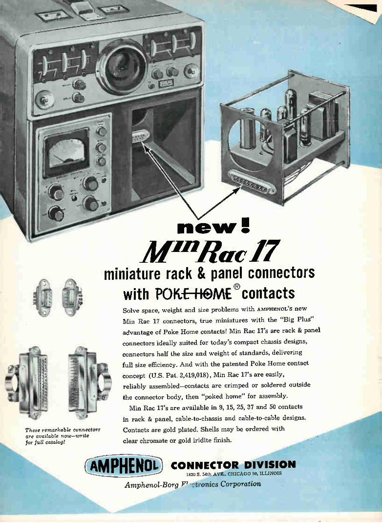
These remarkable connectors are available now—write for full catalog!
MenRue 17 miniature rack & panel connectors
with PO It-E—HOME ® contacts Solve space, weight and size problems with AMPHENOL'S new
Min Rae 17 connectors, true miniatures with the "Big Plus"
advantage of Poke Home contacts! Min Rae 17's are rack & panel
connectors ideally suited for today's compact chassis designs,
connectors half the size and weight of standards, delivering
full size efficiency. And with the patented Poke Home contact
concept (U.S. Pat. 2,419,018) , Min Rae 17's are easily,
reliably assembled—contacts are crimped or soldered outside
the connector body, then "poked home" for assembly.
Min Rae 17's are available in 9, 15, 25, 37 and 50 contacts
in rack & panel, cable-to-chassis and cable-to-cable designs.
Contacts are gold plated. Shells may be ordered with
clear chromate or gold indite finish.
CAMPHENot. CONNECTOR DIVISION 1830 S. 54th AVE., CHICAGO 50, ILLINOIS
Amphenol-Borg tionics Corporation
NEW BOOKS
The Theory of Optimum Noise Immunity By V. A. KOTEL'NIKOV
McGraw-Hill Book Co., Inc., New York, 140 p.
THIS book should prove extremely
worthwhile for any reader with the necessary background who is will-
ing to give it a serious reading.
Although advanced mathematical techniques are not utilized, con-siderable sophistication on the
reader's part has evidently been as-sumed.
Most useful and unusual aspect
of the book is that the author re-mains keenly aware of the practical
implications and limitations of the mathematical relationships devel-
oped. Temptation to lose the reader in a maze of elegant mathematics
has been effectively resisted, a
quality notably absent in most other texts in this field. Although this book can not be considered ideal, it does offer considerable
promise for graduate level work in view of the existing scarcity of suitable books.
The approach used in this text is both clear and direct. Mathe-
matical tools required throughout the book are clearly and concisely stated. Only a minimum of general
introduction and definitions is re-quired since the author does not
give a review of the elements of
probability theory and frequency
analysis which normally take up a substantial part of any text on this topic. Throughout, the author main-
tains a facility for developing the significant relationships in terms that are meaningful. Despite the
conciseness of the text, a number
of practical examples are developed that serve as excellent illustrations.
Perhaps the book's most remark-
able quality is the impressive array of topics that are treated in very little space. It must be read slowly, but is well worth the reading.—
MAURICE C. NEWSTEIN, Technical Research Group, Inc., Syosset, N.Y.
THUMBNAIL REVIEWS Electrical Engineering Fundamentals. By J. P. Neal, McGraw-Hill Book Co., Inc., New York, 1960, 402 p, $8.50. Avowed purpose of this
book to provide a higher-level intro-duction to electrical engineering the-ory than heretofore available is real-ized. Included are sections devoted to measures of electromagnetic characteristics; vector concepts; lo-cal current, electrostatic, magnetic and electromagnetic fields; and elec-tric network structure and analysis. Author assumes student has taken college physics courses in mechanics, electricity and magnetism, and mathematics courses in analytic geometry, algebra and calculus. The rationalized mks system of meas-ures is used throughout.
Cybernetics and Management. By Stafford Beer, John Wiley & Sons, Inc., New York, 211 p, $4.50. Not a textbook nor technical treatise, this book is a general exposition explain-ing the origins, nature and industrial potentiality of the new science of cybernetics. Content is addressed to scientifically educated and imagina-tive managers. Mathematical level never extends beyond algebra. Al-though this is a comprehensive, fundamental and lucid treatment, a supplemental reading of Norbert Wiener's "The Human Use of Human Beings" (not referenced by Beer) could be most profitable.
Vector Analysis. By M. Schwartz, S. Green and W. A. Rutledge, Harper & Brothers, New York, 1960, 556 p, $7.50. Although written primarily to facilitate study by the beginning student, this book also will serve as a reference for advanced students and a self-study text for engineers. Authors consider vector analysis as both a mathematical discipline and a language of physics, thus chapters on applications are interspersed with mathematical theory and de-velopment throughout the text. This is a timely book published as the field takes on increasing importance to electronics engineers.
Two-way Radio. By Allan Lytel, Mc-Graw-Hill Book Co., Inc., New York, 311 p, $9.50. This book con-cerns mobile-to-fixed or mobile-mo-bile communication, bearing mainly on introductory information for technicians handling receive-trans-mit gear. Unfortunately, the au-thor's editors did not put the word mobile into the title; there are hun-dreds of thousands of fixed stations in two-way fixed communication. The text needs more than its sparse discourse on single-sideband radio-telephony. Moreover, the book's price is double that of better books on booksellers' shelves.
Correction. Price and pagination in-formation given in review of "Physics for Students of Science and Engineer-ing—Parts I and II" (p 130, May 13, 1960) applies only to Part I; Part Il is 510 pages and costs $6.
MOLDED RESISTORS
retain their values! S. S. WHITE Molded Resistors retain their original values and never deteriorate due to age!
S. S. WHITE resistors serve dependably in hundreds of commercial... industrial .. and scientific applications. They are characterized by low noise ievel... pre-cision , stability. negative tempera-ture and voltage coefficients. Non-hydro-scope base withstands temperature and humidity They are compact, have ex-cellent stability and mechanical strength.
For full details, write for our Bulletin 5409. We'll be glad to help you apply these high-quality, "all-weather" resistors to your product. Just drop us a line.
FIXED RESISTANCE VALUES RANGE FROM 1000 OHMS TO
10,000,000 M EGOHMS!
65X Molded Resistor I watt 80X Molded Resistor 3 watts
S. S. WHITE INDUSTRIAL DIVISION
Dept. R 10 East 40th St,
New York 16, New York
July 22, 1960 CIRCLE 113 ON READER SERVICE CARD 113
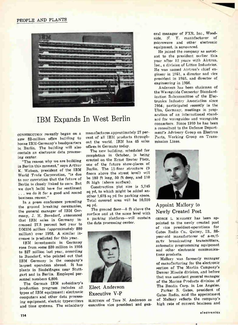
PEOPLE AND PLANTS
IBM Expands In West Berlin
CONSTRUCTION recently began on a new $2-million office building to house IBM-Germany's headquarters in Berlin. The building will also contain an electronic data process-ing center. "The reason why we are building
in Berlin this moment," says Arthur K. Watson, president of the IBM World Trade Corporation, "is due to our conviction that the future of Berlin is closely linked to ours. But we don't build here for sentiment . . . we do it for a good and sound business reason."
In a press conference preceding the ground breaking ceremonies, the general manager of IBM Ger-many, J. H. Borsdorf, announced that IBM sales in Germany in-creased 27.3 percent last year to DM336 million (approximately $80 million) over 1958. A similar in-crease is predicted for this year. IBM investments in Germany
rose from some $20 million in 1958 to $27 million last year, according to Borsdorf, who pointed out that IBM Germany is the company's largest operation abroad. It has plants in Sindelfingen near Stutt-gart and in Berlin. Employed per-sonnel numbers 6,800. The German IBM subsidiary's
production program includes all types of IBM equipment: electronic computers and other data process-ing equipment, electric typewriters and time systems. The subsidiary
manufactures approximately 27 per-cent of all IBM products through-out the world. IBM has 45 sales offices in Germany today. The new building, scheduled for
completion in October, is being erected on the Ernst Reuter Platz, one of the future show-places of Berlin. The 11-floor structure (9 floors above the street level) will be 180 ft long, 50 ft deep, and 110 ft high (above surface).
Construction plot size is 3,745 sq yd, to which might be added an-other 1,675 sq yd for parking space. Total covered area will be 10,510 sq yd. The ground floor-5 ft above the
surface and at the same level with a parking platform—will contain the data processing center.
Elect Anderson Executive V-P ELECTION of Tore N. Anderson as executive vice president and gen-
eral manager of FXR, Inc., Wood-side, N. Y. manufacturer of microwave and other electronic equipment, is announced. He joined the company as assist-
ant to the president earlier this year after 12 years with Airtron, Inc., a division of Litton Industries. He was named Airtron's chief en-gineer in 1951, a director and vice president in 1953, and director of engineering in 1956.
Anderson has been chairman of the Waveguide Connector Standard-ization Subcommittee of the Elec-tronics Industry Association since 1954; participated recently in the Ulm, Germany, meetings in prep-aration of an international stand-ard for waveguides and waveguide connectors. Since 1959 he has been a consultant to the Defense Depart-ment's Advisory Group on Electron Parts, Working Group on Trans-mission Lines.
Appoint Mallory to Newly Created Post GEORGE L. MALLORY has been ap-pointed to the newly created post of vice president-operations for Gates Radio Co., Quincy, Ill., 38-year-old manufacturer of a-m/f-m/tv broadcasting transmitters, automatic programming equipment and other electronic communica-tions products.
Mallory was formerly manager of manufacturing for the electronic section of The Martin Company's Denver Missile division, and before that was assistant general manager of the Marine Products division of The Bendix Corp. in Los Angeles.
Parker S. Gates, president of Gates Radio, said the appointment of Mallory reflects the company's high rate of current business and
114 electronics
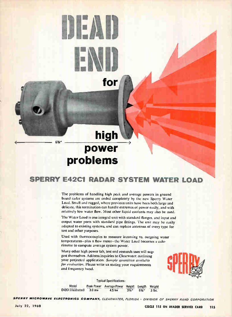
power problems
SPERRY E42C1 RADAR SYSTEM WATER LOAD
The problems of handling high peak and average powers in ground based radar systems are ended completely by the new Sperry Water Load. Small and rugged, where previous units have been both large and delicate, this termination can handle extremes of power easily, and with relatively low water flow. Most other liquid coolants may also be used.
The Water Load is one integral unit with standard flanges, and input and output water ports with standard pipe fittings. The unit may be easily
adapted to existing systems, and can replace antennas of every type for test and other purposes.
Used with thermocouples to measure incoming vs. outgoing water temperatures—plus a flow meter—the Water Load becomes a calo-rimeter to compute average system power.
Many other high power lab, test and research uses will sug-gest themselves. Address inquiries to Clearwater, outlining your projected application. Sample quantities available for evaluation. Please write us stating your requirements and frequency band.
Typical Specifications:
Model Peak Power Average Power Height Length Weight E42CI (illustrated) 3.0 mw 4.5 kw 33/4 " 63/4 " 3 lbs.
SPERRY MICROWAVE ELECTRONICS COMPANY, CLEARWATER, FLORIDA • DIVISION OF SPERRY RAND CORPORATION
July 22, 1960 CIRCLE 115 ON READER SERVICE CARD 115
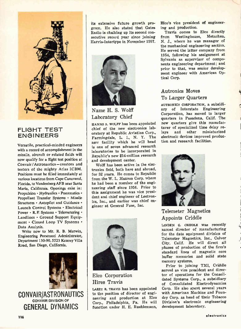
FLIGHT TEST ENGINEERS
Versatile, practical-minded engineers with a record of accomplishment in the missile, aircraft or related fields will now qualify for a flight test position at Convair /Astronautics — creators and testers of the mighty Atlas ICBM. Positions must be filled immediately at various locations from Cape Canaveral, Florida, to Vandenberg AFB near Santa Maria, California. Openings exist in: Propulsion • Hydraulics • Pneumatics • Propellant Transfer Systems • Missile Structures • Autopilot and Guidance • Launch Control Systems • Electrical Power • R. E Systems • Telemetering • Landlines • Ground Support Equip-ment • Closed Loop TV Systems • Data Analysis.
Write now to Mr. R. B. Merwin, Engineering Personnel Administrator, Department 130-90, 5523 Kearny Villa Road, San Diego, California.
CONVAIR/ASTRONAUTICS CONVAIR DIVISION OF
GENERAL DYNAMICS
its extensive future growth pro-gram. He also stated that Gates Radio is chalking up its second con-secutive record year since joining Harris-Intertype in November 1957.
Name H. S. Wolff
Laboratory Chief HANNS S. WOLFF has been appointed chief of the new electronics lab-oratory at Republic Aviation Corp., Farmingdale, L. I., N. Y. The new facility which he will head is one of seven advanced research laboratories to be incorporated in Republic's new $14-million research and development center.
Wolff has been active in the elec-tronics field, both here and abroad, for 32 years. He comes to Republic from the W. L. Maxson Corp. where he had been a member of the engi-neering staff since 1956. Prior to this assignment he was vice presi-dent and chief engineer of Leetron-ics, Inc., and earlier was chief en-gineer at General Fuse, Inc.
reb
Elco Corporation Hires Travis LARRY R. TRAVIS has been appointed to the position of director of engi-neering and production at Elco Corp., Philadelphia, Pa. He will function under H. E. Ruehlemann,
Elco's vice president of engineer-ing and production.
Travis comes to Elco directly from Westinghouse, Metuchen, N. J., where he was manager of the mechanical engineering section. He served the latter company from 1954, following his assignment at Sylvania as supervisor of compo-nents engineering department; and prior to that, was senior develop-ment engineer with American Op-tical Corp.
Autronies Moves To Larger Quarters AUTRONICS CORPORATION, a subsidi-ary of Interstate Engineering Corporation, has moved to larger quarters in Pasadena, Calif. The new quarters give this manufac-turer of specialized time delay re-lays and other miniaturized electronic devices improved produc-tion and research facilities.
Telemeter Magnetics
Appoints Criddle LINDEN G. CRIDDLE was recently named director of manufacturing for the data equipment division of Telemeter Magnetics, Inc., Culver City, Calif. He will direct all phases of production of the firm's standard lines of magnetic core buffer memories and solid state memory systems.
Prior to joining TMI, Criddle served as vice president and direc-tor of operations for the Consoli-dated Systems Corp., a subsidiary of Consolidated Electrodynamics Corp. He also spent several years with American Machine and Foun-dry Corp. as head of their Tobacco Division's electronic engineering development laboratory.
116 electronics
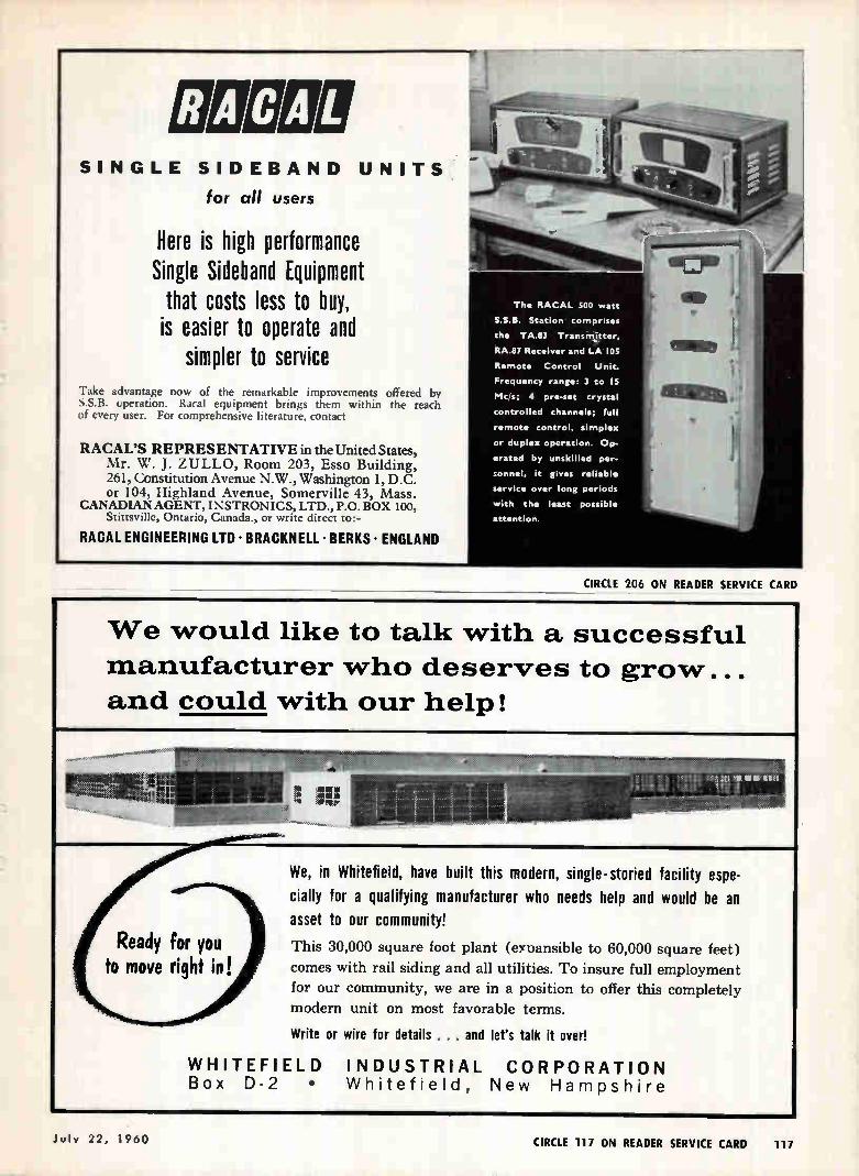
SINGLE SIDEBAND UNITS
for all users
Here is high performance Single Sideband Equipment that costs less to buy,
is easier to operate and simpler to service
Take advantage now of the remarkable improvements offered by S.S.B. operation. Racal equipment brings them within the reach of every user. For comprehensive literature, contact
RACAL'S REPRESENTATIVE in theUnited States, Mr. W. J. ZULLO, Room 203, Esso Building, 261, Constitution Avenue N.W., Washington 1, D.C. or 104, highland Avenue, Somerville 43, Mass.
CANADIAN AGENT, I NSTRONICS, LTD., P.O. BOX 100, Stittsville, Ontario, Canada., or write direct to:-
RACAL ENGINEERING LTD • BRACKNELL • BERKS • ENGLAND
CIRCLE 206 ON READER SERVICE CARD
The RACAL SOO watt
S.S.B. Station comprises
the TAJO Transinitter,
RA.87 Receiver and LA 105
Remote Control Unit.
Frequency range: 3 to IS
Mc/s; 4 pre-set crystal
controlled channels; full
remote control, simplex
or duplex operation. Op-
erated by unskilled per-
sonnel, it gives reliable
service over long periods
with the least possible
attention.
We would like to talk with a successful
manufacturer who deserves to grow...
and could with our help!
We, in Whitefield, have built this modern, single-storied facility espe-
cially for a qualifying manufacturer who needs help and would be an
asset to our community!
This 30,000 square foot plant (expansible to 60,000 square feet)
comes with rail siding and all utilities. To insure full employment
for our community, we are in a position to offer this completely
modern unit on most favorable terms.
Write or wire for details . . . and let's talk it over!
WHITEFIELD INDUSTRIAL CORPORATION Box D-2 • VVhitefield, New Hampshire
July 22, 1960 CIRCLE 117 ON READER SERVICE CARD 117
EMPLOYMENT OPPORTUNITIES
ACF ELECTRONICS DIVISION
ELECTRO-PHYSICS LABORATORIES Responsible assignments in furthering the state-of-the-art of Ionospheric Physics, combining competitive salaries and unusual growth potential, are offered to men who can contribute. Our present needs are for:
eleCeietWeie eltyinieee(4
/(11 Yleii4.041 eîîyéneeità
FOR RESEARCH PROGRAMS IN
IONOSPHERIC PROPAGATION (3,4 HF COMMUNICATIONS
SENIOR DEVELOPMENT ENGINEERS Advanced degree in E.E. or Physics preferred. Must be familiar with present state-of-the-art in the design of advanced HF receivers and transmitters and possess working knowledge of modern HF networks employing ferrites and metallic tape cores. Strong theoretical background in modern linear circuit theory desired. Will carry -out laboratory development and implementation of new HE communication systems.
SENIOR ELECTRONIC ENGINEERS Advanced degree in E.E. preferred. Must be familiar with conventional pulse circuit designs and applications. Technical background should include substantial experience in data process and data recovery systems using both analog and digital techniques. Knowledge of principles and application of modern information theory including correlation techniques helpful. Will be responsible for the design of sub-systems,
JUNIOR ELECTRONIC ENGINEERS To assist Senior Engineers and Scientists in the development of HF communica-tions and data process equipment. Should have formal electronics schooling and 2 years experience in circuit design, checkout or analysis of HF communications, Radar Pulse, Analog/Digital or Data Recovery eguipment. Construction of prow- À types of new and interesting equipment and design of individual components of communications and data processing systems will comprise the major efforts of selected applicants. .
FIELD STATION ENGINEERS B.S.E.E. or equivalent, consisting of combined civilian or military technical school, with work experience. Presently employed as a field engineer or project engineer with valid 1st or 2nd Class FCC license and a good command of some of the following; Radar, preferably high power; HF long-distance communications sys-tems; Tropospheric or Ionospheric scatter systems. Must be willing to accept assignments in areas where dependents are not permitted for periods of up to one year. Differential paid for overseas assignments.
The Electro-Physics Laboratories are located in the suburban Washington, D.C. area, where post-graduate study is available in several nearby universities. Housing is plentiful in attractive, well-established neighborhoods. Our relocation allowance is liberal.
All inquiries will be held in strictest confidence and answered prom puy. Please send resume to:
PROFESSIONAL EMPLOYMENT DEPARTMENT
ACF ELECTRONICS DIVISION
Industries, Incorporated
Riverdale, Maryland
Electronics Engineers
BSEE, electronics experience, U.S. citizenship required.
For test and evaluation work on highly sophisticated elec-tronic equipment. Creative imagination essential.
Jobs on East coast with con-siderable overseas travel— non-continuous about 4 months a year.
Salary $5500 to $8800 depend-ent upon experience and abil-ity.
Write giving age, education, experience, address, telephone
to:
P-4775, Electronics Class Adv. Div.,
P. 0. Box 12, N. Y. 1114 N. Y
ADDRESS BOX NO. REPLIES TO: Box No. Classified Ads'. Dir. of thia publication.
Send to office nearest you. NEW YORK 36: P. 0. Box 12 CHICAGO 11: 520 N. Michigan Ave. SAN FRANCISCO 4: 68 Poet St.
POSITIONS VACANT
Senior Electronics Technician in design shop. Work involves construction and testing of in-strumentation and control circuitry for chem-ical research, supervision of graduate stu-dents, and some maintenance. Two years ex-perience required, college work desirable. salary open. P-4804. Electronics.
Chief Research Consultant Wanted for ap-plied research, development, evaluation and testing. The Laboratory is conducting re-search, development, system studies, and engineering evaluation in the fields of sonar, radio, radar, infrared and related physical sciences. Also provides technical assistance and consultation to the Forces Afloat, naval shore activities, including other naval labs. and government contractors on problems of mutual concern. Salary within the range of $12.500 to $19,000 per year, probable en-trance salary 815,000. Salary and qualifica-tions of applicant selected subject to ap-proval of U. S. Civil Service Commission. In-terested persons are invited to contact: In-dustrial Relations Officer, U. S. Navy Under-water Sound Laboratory, Fort Trumbull, New London, Connecticut.
EMPLOYMENT PROBLEM?
When you ore in need of specialized men
for specialized jobs, contact them through
an employment ad in this publication.
118 electronics
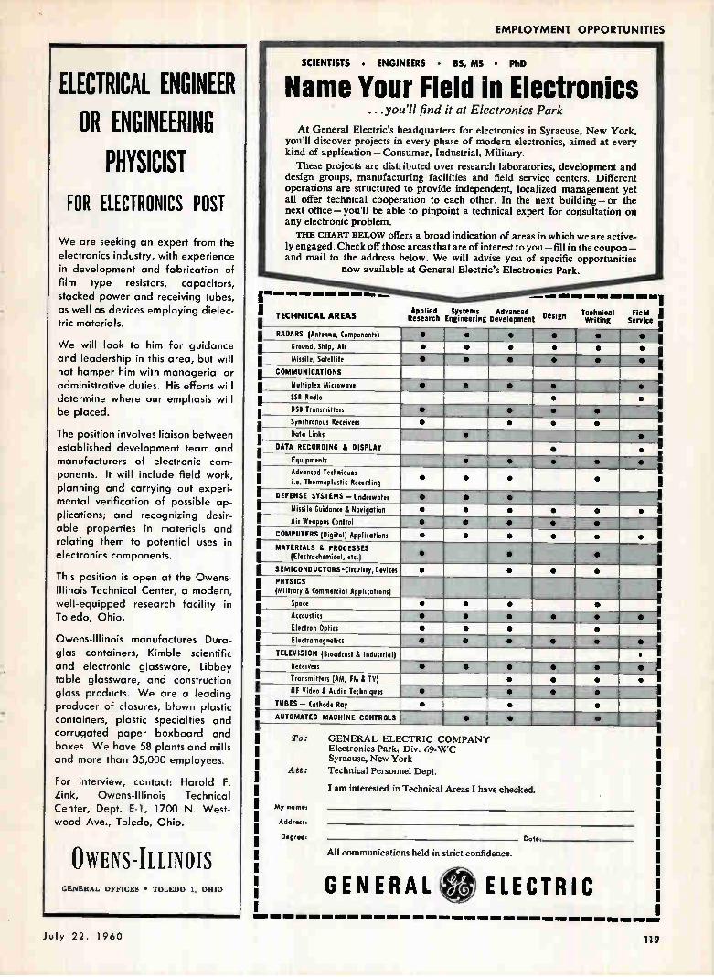
EMPLOYMENT OPPORTUNITIES
ELECTRICAL OR ENGINEERING
PHYSICIST FOR ELECTRONICS POST
ENGINEER
We are seeking an expert from the electronics industry, with experience in development and fabrication of film type resistors, capacitors, stacked power and receiving tubes, as well as devices employing dielec-tric materials.
We will look to him for guidance and leadership in this area, but will not hamper him with managerial or administrative duties. His efforts will determine where our emphasis will be placed.
The position involves liaison between established development team and manufacturers of electronic com-ponents. It will include field work, planning and carrying out experi-mental verification of possible ap-plications; and recognizing desir-able properties in materials and relating them to potential uses in electronics components.
This position is open at the Owens-Illinois Technical Center, a modern, well-equipped research facility in Toledo, Ohio.
Owens-Illinois manufactures Dura-glas containers, Kimble scientific and electronic glassware, Libbey table glassware, and construction glass products. We are a leading producer of closures, blown plastic containers, plastic specialties and corrugated paper boxboard and boxes. We have 58 plants and mills and more than 35,000 employees.
For interview, contact: Harold F. Zink, Owens-Illinois Technical Center, Dept. E-1, 1700 N. West-wood Ave., Toledo, Ohio.
OWENS-ILLINOIS GENERAL OFFICES • TOLEDO I. OHIO
SCIENTISTS • ENGINEERS • 85, MS • PhD
Name Your Field in Electronics ...you'll find it at Electronics Park
At General Electric's headquarters for electronics in Syracuse, New York,
you'll discover projects in every phase of modern electronics, aimed at every kind of application — Consumer, Industrial, Military.
These projects are distributed over research laboratories, development and design groups, manufacturing facilities and field service centers. Different
operations are structured to provide independent, localized management yet
all offer technical cooperation to each other. In the next building — or the
next office — you'll be able to pinpoint a technical expert for consultation on any electronic problem.
THE CHART BELOW offers a broad indication of areas in which we are active-
ly engaged. Check off those areas that are of interest to you — fill in the coupon —
and mail to the address below. We will advise you of specific opportunities
now available at General Electric's Electronics Park.
I TECHNICAL AREAS Applied Systems Advanced Design Research Engineering Development
Technical Field I Writing Service •
RADARS (Antenna, Components) • • • • • • III l
Ground, Ship, Air • • • • • • i
Missile, Satellite e • • • • • I
COMMUNICATIONS i Multiplex Microwave • • • • • I
SS8 Radio • • i DSB Transmitters • • • •
Synchronous Receivers • • • • I
Data Links s • I , DATA RECORDING & DISPLAY • e 1
.
Equipments • et • • • I
Advanced Techniques i.e. Thermoplastic Recording
• • • •
I
I
DEFENSE SYSTEMS — Underwater • • • I
---1 Missile Guidance & Navigation • • a • • •
Air Weapons Control • • • • I
COMPUTERS (Digital) Applications • • • • • • I MATERIALS & PROCESSES
(Electrochemical, etc.) • • • I
I SEMICONDUCTORS-Circuitry,Devices • • • • PHYSICS (Military & Commercial Applications)
Space • • • •
Accoustics • • • • e •
Electron Optics • • • •
Electromagnetics 0 • • • • •
TELEVISION (Broadcast & Industrial) •
• Receivers • • • 5 e
Transmitters (AM, FM & TV) • • • •
HF Video & Audio Techniques • • • •
TUBES — Cathode Roy • • •
AUTOMATED MACHINE CONTROLS • • 1 _ • AO
To: GENERAL ELECTRIC COMPANY Electronics Park, Div. 69-WC Syracuse, New York
Att: Technical Personnel Dept.
I am interested in Technical Areas I have checked.
My nomes
Address:
Degree: Date:
All communications held in strict confidence.
GENERAL 4 ELECTRIC
July 22, 1960 119
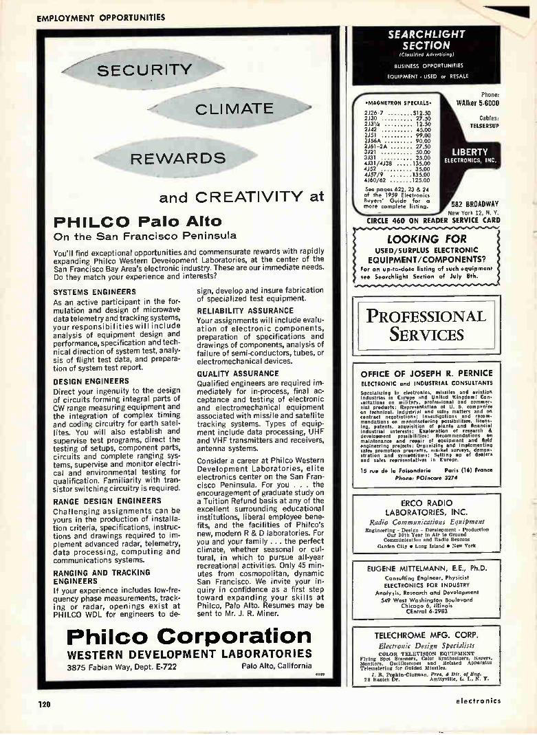
EMPLOYMENT OPPORTUNITIES
SEARCHLIGHT SECTION
SECURITY
CLIMATE
REWARDS
and CREATIVITY at
PHILCO Palo Alto On the San Francisco Peninsula
You'll find exceptional opportunities and commensurate rewards with rapidly expanding Philco Western Development Laboratories, at the center of the San Francisco Bay Area's electronic industry. These are our immediate needs. Do they match your experience and interests?
SYSTEMS ENGINEERS As an active participant in the for-mulation and design of microwave data telemetry and tracking systems, your responsibilities will include analysis of equipment design and performance, specification and tech-nical direction of system test, analy-sis of flight test data, and prepara-tion of system test report.
DESIGN ENGINEERS Direct your ingenuity to the design of circuits forming integral parts of CW range measuring equipment and the integration of complex timing and coding circuitry for earth satel-lites. You will also establish and supervise test programs, direct the testing of setups, component parts, circuits and complete ranging sys-tems, supervise and monitor electri-cal and environmental testing for qualification. Familiarity with tran-sistor switching circuitry is required.
RANGE DESIGN ENGINEERS Challenging assignments can be yours in the production of installa-tion criteria, specifications, instruc-tions and drawings required to im-plement advanced radar, telemetry, data processing, computing and communications systems.
RANGING AND TRACKING ENGINEERS If your experience includes low-fre-quency phase measurements, track-ing or radar, openings exist at PHILCO WDL for engineers to de-
sign, develop and insure fabrication of specialized test equipment.
RELIABILITY ASSURANCE Your assignments will include evalu-ation of electronic components, preparation of specifications and drawings of components, analysis of failure of semi-conductors, tubes, or electromechanical devices.
QUALITY ASSURANCE Qualified engineers are required im-mediately for in-process, final ac-ceptance and testing of electronic and electromechanical equipment associated with missile and satellite tracking systems. Types of equip-ment include data processing, UHF and VHF transmitters and receivers, antenna systems.
Consider a career at Phi lco Western Development Laboratories, elite electronics center on the San Fran-cisco Peninsula. For you . . . the encouragement of graduate study on a Tuition Refund basis at any of the excellent surrounding educational institutions, liberal employee bene-fits, and the facilities of Philco's new, modern R & D laboratories. For you and your family ... the perfect climate, whether seasonal or cul-tural, in which to pursue all-year recreational activities. Only 45 min-utes from cosmopolitan, dynamic San Francisco. We invite your in-quiry in confidence as a first step toward expanding your skills at Philco, Palo Alto. Resumes may be sent to Mr. J. R. Miner.
Philco Corporation WESTERN DEVELOPMENT LABORATORIES 3875 Fabian Way, Dept. E-722 Palo Alto, California
6659
(Classified Advertising)
BUSINESS OPPORTUNITIES
EQUIPMENT - USED or RESALE
e" MAGNETRON SPECIALS-
2.126-7 $12.50 2130 27.50 2J3V4 12.50 2142 45.00 2151 99.00 2J56A 90.00 2J61-2A 27.50 3121 50.00 3J31 35.00 4J31/4138 135.00 4152 35.00 4J57/9 135.00 4.160/62 125.00
See pages 622, 23 8. 24 of the 1959 Electronics Buyers' Guide for a more complete listing.
LIBERTY ELECTRONICS, INC.
Phone:
WAlker 5-6000
Cables:
TELSERSUP
582 BROADWAY NPV7 York 12, N. Y.
CIRCLE 460 ON READER SERVICE CARD
LOOKING FOR USED/SURPLUS ELECTRONIC
EQUIPMENT/COMPONENTS? For an up-to-date listing of such equipment
see Searchlight Section of July 8th.
PROFESSIONAL SERVICES
OFFICE OF JOSEPH R. PERNICE ELECTRONIC and INDUSTRIAL CONSULTANTS
Specializing in electronics, missiles and aviation industries in Europe and United Kingdom: Con-sultations on military, professional and commer-cial products: Representation of U. S. companies on technical. industrial and sales matters and on contract negotiations: Investigations and recom-mendations on manufacturing possibilities, licens-ing, patents, acquisition of plants and financial industrial interests: Exploration of research & development possibilities: Recommendations on maintenance and repair of equipment and field engineering projects: Organizing and implementing sales promotion programs, market surveys, demon• stration and symposiums: Setting up of dealers and sales representatives in Europe.
15 rue de la Faisanderie Paris (16) France
Phone: POIncare 3274
ERCO RADIO LABORATORIES, INC.
Radio Communications Equipment Engineering - Design - Development - Production
Our 30th Year in Air to Ground Communication and Radio Beacons
Garden City • Long Island • New York
EUGENE MITTELMANN, E.E., Ph.D. Consulting Engineer, Physicist
ELECTRONICS FOR INDUSTRY
Analysis, Research and Development
549 West Washington Boulevard Chicago 6, Illinois CEntral 6-2983
TELECHROME MFG. CORP.
Electronic Design Specialists COLOR 'TELEVISION EQUIPMENT
Flying Spot Scanners, Color Synthesizers, Reyers, Monitors, Oscilloscopes and Related Apparatus Telemetering for Guided Missiles.
J. R. Popkin-Clurman, Pres. it Dir. of E*0. 28 Renick Dr. Amityville, I., I., N. Y.
120 electronics
INDEX TO ADVERTISERS
118P Audited Paid Circulation
Airpax Products Co
Amnhenol-Borg Electronics Corn. Connector Div.
Anaconda Wire & Cable Co 32,
Atiee Corp.
Avnet Electronics
Barnateact Still & Sterilizer Co
Beaver Gear Works, Inc 86
Corn. Ec'in-• Pioneer 94, 95
Bla--Enox Company 107
Bruno-New York Industries Corp 122
Brush Instrument, Div. Clevite Corp. 17. 18
112
38
82
28
14
Conv-dr/Astronautics Div. of General Dynamics 116
Convair/Pomona Div. of General Dynamics 35, 86
Dean and Benson Research, Inc 6
Dow Corning Corp 2 8
Driver Co., Wilbur B 41
duT'ont de Nemours. & Co. Pigments 24. 25
Edo Corporation
Edwards High Vacuum Inc
Electro Motive Mfg. Co., Inc
110
85
44
rood Machinery & Chemical Corp.... 42
Gardner-Denver 81
Garrett Corporation, The 122
Gate- Radio Co
General Aniline & Film Corp. fl-alid Div. 27
Gen-rn` Electric Co. eemiconcluctor Pdta. 30. 31
Power Tubes 109
Silicon" Pas. Dept 34
Granger Associates 91
Green Instrument Co 26
Hart Manufacturing Co 96
Hermetic Seal Transformer Co 50
Hewlett Packard Co 2nd Cover
Hexacon Electric Co 86
Hill Electronics Inc 111
Hitemp Wires Inc 89
Honeywell 102
International Business Machines Corp.
International Electronic Industries, Inc.
International Nickel Company, Inc
78 Jettron Products 102
Jones, H. B. Div. of Cinch Mfg. Co 110
Jones & Lamson Machine Co 108
Kintel, A Division of Cohu Electronics Inc. 3rd Cover
Kyoritsu Electrical Instruments Works. Ltd. 85
Littelfuse 85
Mallory and Co., Inc., P. R 16
Marion Electrical Instrument Co 109
Markem Machine Co 98
Martin Co. 110
Melaba 77
Minnesota Mining & Mfg. Co.. Chem Div. 97
National Company 83
Nippon Electric Co 49
North Atlantic Industries, Inc 87
North Electric Co 75
Ohm Ito Mfg. Co 9
Parker Seal Company 104
Philips Gloeilampe Fabrieken, N. V..12, 18
Potter & Brumfield 7
Racal Engineering Ltd 117
Radio Corporation of America...4th cover 48
Raytheon Company 5 73
Remington Rand 100
Sarkes Tarzian Inc 22
Sierra Electronic Corp 10
Space Technology 15
Spectrol Electronics Corp 92, 93
Sperry Electronic Div. Sperry-Rand Corp. 99
Sperry Gyroscope Div. of Sperry" Rand Corp. 115
Sprague Electric Co 46, 47
Sprague Electric Co. Dynacore Div. 100
Texas Instruments, Inc. Semiconductor-Componente Div. .... 52
51 United Aircraft Corp. Nordon Div. 20
21 United Electro Dynamics Inc 108
I 9 United States Testing Co 79
To PROTECT
PIPES or CABLES
from HIGH TEMPERATURE
EXPOSURES...
THERM AZ I P is available in asbestos or fiberglass Zippertubing that offers insulation for pipes and
cables as well as an abrasion-proof
jacket. Jacket and insulation are applied in a single operation, so entire cost of THEsmAzIP applica-tion is less than some insulations alone!
TH ER M AZI P jacketing per-mits inspection and maintenance of cable or pipe by simply zipping
open. After inspection is com-
pleted, THERMAZIP can be zipped closed in a matter of seconds.
Send for name of nearest field rep-resentative and complete literature
on Zippertubing insulating mate-
rials that will withstand extreme
high or low temperatures! Pat. or Pat. Applied For.
THE Zippertubing co. 752 S San Pedro St Los Angeles 14. Calif.
DURING WESCON VISIT US AT BOOTH 2320
July 22, 1960 CIRCLE 121 ON READER SERVICE CARD 121
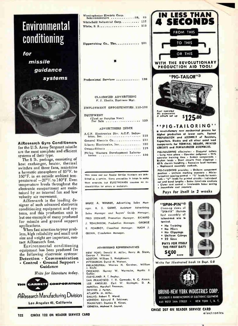
AiResearch Gyro Conditioners for the U.S. Army Sergeant missile are the most complete and efficient systems of their type. The 8 lb. package, consisting of
heat exchanger, heater, thermal switches and three fans, maintains a hermetic atmosphere of 85°F. to 160°F. in an outside ambient tem-perature of —20°F. to 140°F. Even temperature levels throughout the electronic compartment are main-tained by an internal fan and low velocity air movement. AiResearch is the leading de-
signer of such advanced electronic conditioning equipment and sys-tems, and this production unit is but one example of many produced for missile and ground support applications. When fast attention to your prob-
lem, high reliability and small unit size and weight are important, con-tact AiResearch first.
Environmental conditioning equipment has been produced for the following electronic systems: Detection • Communication • Control • Ground Support •
Guidance
THE
Write for literature today.
CORPORATION
niPesearch Manufacturing Division Los Angeles 45, California
Westinghouse Electric Corp. Semiconductors 28, 29
Whitefield Industrial Corp 11
White, S S 113
Zippertubing Co., The
•
121
Professional Services 120
CLASSIFIED ADVERTISING
F. J. Eberle, Business Mgr.
EMPLOYMENT OPPORTUNITIES. 118-120
EQUIPMENT
(Used or Surplus New) For Sale 120
ADVERTISERS INDEX
A.C.F. Electronics Div. A.C.F. Indus-tries, Inc. 118
General Electric Co 119
Liberty Electronics, Inc 120
Owens-Illinois 119
Philco Western Development Labora-tories 120
This index and our Reader Service Numbers are pub-
lished as a service. Every precaution is taken to make
them accurate. but ELECTRONICS assumes no re-
sponsibilities for errors or omissions.
BRUCE A. WINNER, Advertising Sales Man-
ager. R. S. QUINT, Assistant Advertising
Sales Manager and Buyers' Guide Manager.
FRED STEWART, Promotion Manager. RICHARD
J. TOMLINSON, Production Manager. GEORGE
E. POMEROY, Classified Manager. HUGH J.
QUINN, Circulation Manager.
ADVERTISING REPRESENTATIVES
NEW YORK: Donald H. Miller, Henry M. Shaw, George F. Werner. BOSTON: William S. Hodgkinson.
PITTSBURGH: David M. Watson.
PHILADELPHIA: Warren H. Gardner, William J. Boyle. CHICAGO: Harvey W. Wernecke, Martin J. Galley. CLEVELAND: P. T. Fegley. SAN FRANCISCO: T. H. Carmody, R. C. Alcorn.
LOS ANGELES: Carl W. Dysinger, D. A.
McMillan, Marshall Freeman.
DENVER: J. Patten.
ATLANTA: M. Miller.
DALLAS: Robert T. Wood.
LONDON. Edward E. Schirmer. FRANKFURT: Stanley R. Kimes.
GENEVA: Michael R. Zeynel.
e IN LESS THAN \ 4 SECONDS
FROM THIS
WITH THE REVOLUTIONARY PRODUCTION AID TOOL!
"PIG-TAILOR"
Foot operated No accessories .3 minute set up
$125.00
"PIG-TAILORING" o revolutionary new mechanical process for
higher production at lower costs. Fastest
PREPARATION and ASSEMBLY of Resistors,
Capacitors, Diodes and all other axial lead
components for TERMINAL BOARDS, PRINTED
CIRCUITS and MINIATURIZED ASSEMBLIES.
PIG-TAILORING eliminates: • Diagonal cutters • Long nose pliers • Operator judgment • 90% operator training time • Broken components • Broken leads • Short circuits from clippings •
65 3/4 chassis handling • Excessive lead tautness • Haphazard assembly methods.
PIG-TAILORING provides: • Uniform component position • Uniform marking exposure • Minia-turization spacing control • "S" leads for termi-nals . "U" leads for printed circuits • Individual
cut and bend lengths • Better time/rate analysis . Closer cost control • Invaluable labor saving • Immediate cost recovery.
Pays for itself in 2 weeks
"SPIN-PIN"® Close-up views of "SPIN-PIN" illustrate
fast assembly of
tailored-lead wire to
terminal.
• No Training
• No Pliers
• No Clippings
• Uniform Crimps
• 22 Sizes
PAYS FOR ITSELF
THE FIRST DAYI
$500 EACH
Write for illustrated book to Dept. E-8
BRUNO-NEW YORK INDUSTRIES CORP. DESIGNERS & MANUFACTURERS OF ELECTRONIC EQUIPMENT
460 WEST 34th STREET • NEW YORK I, N. Y.
122 CIRCLE 122 ON READER SERVICE CARD
CIRCLE 207 ON READER SERVICE CARD electron CS
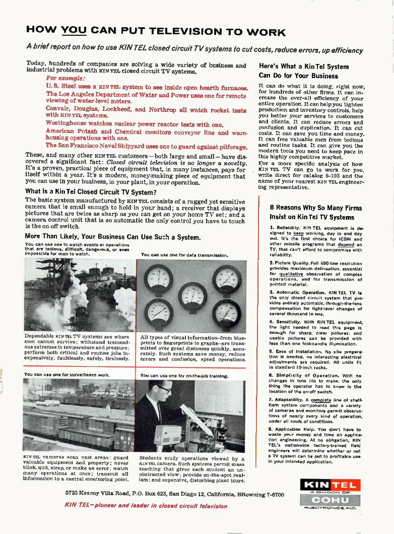
HOW YOU CAN PUT TELEVISION TO WORK
A brief report on how to use KIN TEL closed circuit TV systems to cut costs, reduce errors, up efficiency
Today, hundreds of companies are solving a wide variety of business and industrial problems with lux TEL closed circuit TV systems.
For example:
U. S. Steel uses a KIN TEL system to see inside open hearth furnaces. The Los Angeles Department of Water and Power uses one for remote viewing of water-level meters.
Convair, Douglas, Lockheed, and Northrop all watch rocket tests with KIN TEL systems.
Westinghouse watches nuclear power reactor tests with one.
American Potash and Chemical monitors conveyor line and ware-housing operations with one.
The San Francisco Naval Shipyard uses one to guard against pilferage.
These, and many other KIN TEL customers — both large and small — have dis-covered a significant fact: Closed circuit television is no longer a novelty. It's a proven, practical piece of equipment that, in many instances, pays for itself within a year. It's a modern, money-making piece of equipment that you can use in your business, in your plant, in your operation.
What Is a Kin Tel Closed Circuit TV System?
The basic system manufactured by KIN TEL consists of a rugged yet sensitive camera that is small enough to hold in your hand; a receiver that displays pictures that are twice as sharp as you can get on your home TV set; and a camera control unit that is so automatic the only control you have to touch is the on-off switch.
More Than Likely, Your Business Can Use Buz!) a System. You can use one to watch events or operations that are tedious, difficult, dangerous, or even impossible for men to watch.
Dependable KIN TEL TV systems see where men cannot survive; withstand tremend-ous extremes in temperature and pressure; perform both critical and routine jobs in-expensively, faultlessly, safely, tirelessly.
You can use one for data transmission.
All types of visual information-from blue-prints to fingerprints to graphs-are trans-mitted over great distances quickly, accu-rately. Such systems save money, reduce errors and confusion, speed operations.
You can use one for surveillance work.
KIN TEL cameras scan vast areas; guard valuable equipment and property; never blink, quit, sleep, or make an error; watch many operations at once; transmit all information to a central monitoring point.
You can use one for on-the-job training.
Students study operations viewed by a KIN TEL camera. Such systems permit mass teaching that gives each student an un-obstructed view; provide on-the-spot real-ism; end expensive, disturbing plant tours.
Here's What a Kin Tel System
Can Do for Your Business
It can do what it is doing, right now, for hundreds of other firms. It can in-crease the over-all efficiency of your entire operation. It can help you tighten production and inventory controls, help you better your services to customers and clients. It can reduce errors and confusion and duplication. It can cut costs. It can save you time and money. It can free valuable men from tedious and routine tasks. It can give you the modern tools you need to keep pace in this highly competitive market. For a more specific analysis of how KIN TEL TV can go to work for you, write direct for catalog 6-103 and the name of your nearest KIN TEL engineer-ing representative.
8 Reasons Why So Many Firms
Insist on Kin Tel TV Systems
1. Reliability. KIN TEL equipment is de-signed to keep working, day in and day
out. It's the first choice for ICBM and other missile programs that depend on
TV, that can't afford to compromise with reliability.
2. Picture Quality. Full 650-line resolution
provides maximum delineation, essential for qualitative observation of complex operations, and for transmission of printed material.
3. Automatic Operation. KIN TEL TV is the only closed circuit system that pro-vides entirely automatic, through-the-lens compensation for light-level changes of several thousand to one.
4. Sensitivity. With KIN TEL equipment,
the light needed to read this page is enough for sharp, clear pictures; and usable pictures can be provided with
less than one foot-candle illumination.
5. Ease of Installation. No site prepara-tion is needed, no interacting electrical
adjustments are required. All units fit in standard 19-inch racks.
6. Simplicity of Operation. With no changes in lens iris to make, the only
thing the operator has to know is the location of the on-off switch.
7. Adaptability. A complete line of shelf-item system components and a variety
of cameras and monitors permit observa-tions of nearly every kind of operation. under all kinds of conditions.
8. Application Help. You don't have to waste your money and time on applica-tion engineering. At no obligation, KIN TEL's nationwide factory-trained field engineers will determine whether or not
a TV system can be put to profitable use in your intended application.
5725 Kearny Villa Road, P.O. Box 623, San Diego 12, California, BRowning 7-6700
KIN TEL—pioneer and leader in closed circuit television
KIN TEL 1.1%,1510,4
00HU me_m•-re.t.1=1P,IICIfi.
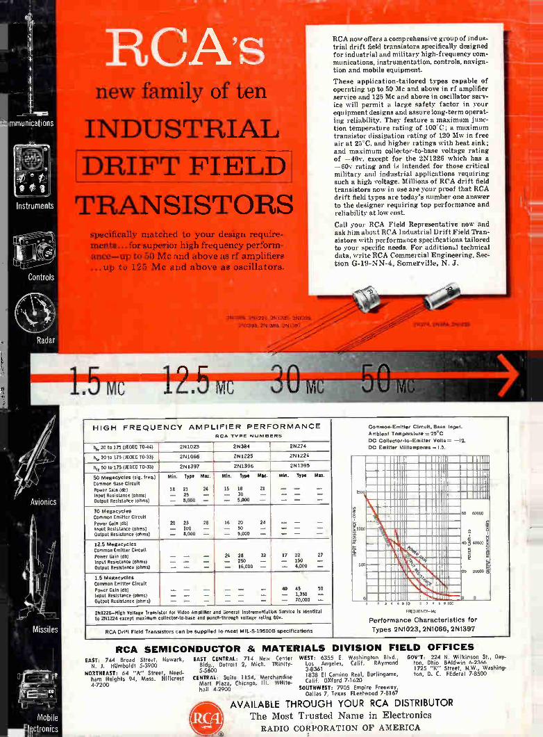
mmunications
Instruments
Controls
Radar
new family of ten
INDUSTRIAL
IDRIFT FIELD]
TRANSISTORS specifically matched to your design require-ments...for superior high frequency perform-ance—up to 50 Mc and above as rf amplifiers ...up to 125 Mc and above as oscillators.
2N1066, 2N1224, 2N1225, 2NI 226,
2N1395, 2N1396. 2N1397
-- 1.5 vc 12.5 mc
Avionics
Missiles
Common-Emitter Circult, Base Input.
Ambient Temperature = 25°C
DC Collector to-Emitter Volts= —12.
DC Emitter Milliamperes =1.5.
HIGH FREQUENCY AMPLIFIER PERFORMANCE
h, 20 to 175 (1EDEC TO-44)
h, 20 to 175 (1EDEC TO-33)
0, 50 to 175 (1EDEC TO-33)
50 Megacycles (sig. freq.) Common Base Circuit
Power Gain (db) Input Resistance (ohms) Output Resistance (ohms)
30 Megacycles Common Emitter Circuit Power Gain (db) Input Resistance (ohms) Output Resistance (ohms)
12.5 Megacycles Common Emitter Circuit Power Gain (db) Input Resistance (ohms) Output Resistance (ohms)
1.5 Megacycles Common Emitter Circuit Power Gain (db) Input Resistance (ohms) Output Resistance (ohms)
2N1023
2N1066
2N1397
MM. Type Max.
18 21 25 8,000
24
29 23 26 — 100 — — 8,000 —
RCA TYPE NUMBERS
2 N384
2N1225
2N1396
Mln. Type Max.
15 18 — 30 — 5,000
16 20 — 50 — 5,000
24 28 — 250 — 18,000 —
21
24
2N274
2N1224
2N1395
Min. Type Mu.
32 17 22 27 — 150 — — 4,000 —
40 45 50 — 1,350 — — 70,000 —
2N1226—High Voltage Transistor for Video Amplifier and General Instrumentation Service Is Identical to 2N1224 except maximum collector-to-base and punch-through voltage rating 60v.
RCA Drift Field Transistors can be supplied to meet MIL-S.19500B specifications
RCA SEMICO EAST: 744 Broad Street, Newark,
N. J. HUmboldt 5-3900
NORTHEAST: 64 "A" Street, Need-ham Heights 94, Mass. HIlIcrest 4-7200
RCA now offers a comprehensive group of indus-trial drift field transistors specifically designed for industrial and military high-frequency com-munications, instrumentation, controls, naviga-tion and mobile equipment.
These application-tailored types capable of operating up to 50 Mc and above in rf amplifier service and 125 Mc and above in oscillator serv-ice will permit a large safety factor in your equipment designs and assure long-term operat-ing reliability. They feature a maximum junc-tion temperature rating of 100°C; a maximum transistor dissipation rating of 120 Mw in free air at 25°C, and higher ratings with heat sink; and maximum collector-to-base voltage rating of —40v, except for the 2N1226 which has a —60v rating and is intended for those critical military and industrial applications requiring such a high voltage. Millions of RCA drift field transistors now in use are your proof that RCA drift field types are today's number one answer to the designer requiring top performance and reliability at low cost.
Call your RCA Field Representative now and ask him about RCA Industrial Drift Field Tran-sistors with performance specifications tailored to your specific needs. For additional technical data, write RCA Commercial Engineering, Sec-tion G-19-NN-4, Somerville, N. J.
500
o
0 .00-40.
2N274, 2N384. 2NI023
60 60:00
• Ki 2 3 4 6 4100
FREQUENCY-Mc
Performance Characteristics for Types 2N1023, 2N1066. 2N13 9 7
NDUCTOR 8( MATERIALS DIVISION FIELD OFFICES EAST CENTRAL: 714 New Center
Bldg., Detroit 2, Mich. TRinity-5-5600
CENTRAL: Suite 1154, Merchandise Mart Plaza, Chicago, Ill. WHIte-hall 4-2900
WEST: 6355 E. Washington Blvd., GOV'T: 224 N. Wilkinson St., Day-Los Angeles, Calif. RAymond ton, Ohio BAldwin 6-2366 3-8361 1725 "K" Street, N.W., Washing-1838 El Camino Real, Burlingame, ton, D. C. FEderal 7-8500 Calif. OXford 7-1620
SOUTHWEST: 7905 Empire Freeway, Dallas 7, Texas Fleetwood 7-8167
AVAILABLE THROUGH YOUR RCA DISTRIBUTOR The Most Trusted Name in Electronics
RADIO CORPORATION OF AMERICA