the pinpointer i - safety | service · pdf filethe pinpointer i an unshielded cable fault...
TRANSCRIPT

Page 1
The
Pinpointer I
AN UNSHIELDED CABLE FAULT LOCATOR
(Available Online at www.hjarnett.com)
Operations Manual
H.J. Arnett Industries, L.L.C. 20460 Avery Court Tualatin, OR 97062 503-692-4600

Page 2
The Pinpointer
An Unshielded Cable Fault Locator
OPERATIONS MANUAL
Table of Contents Page
I. Description 3
A. General 3
B. The Transmitter 3
C. The Detector 4
D. Other Component 4
II. Operation
A. General 8
B. Transmitter Connections 8
C. Calibrating the Fault Impedance Indicator 8
D. Connecting to Faulted Cable & Ground 9
E. Detector Connections 11
F. Locating the Fault 11
G. Locating a Fault at the Riser 13
III. Theory of Operations 14
IV. Optional Rechargeable Battery Kit Instructions 15
V. Troubleshooting 16
VI. Parts List 17
VII. Specifications 18
Illustrations
Fig. 1 Fault Impedance Indicator 3
Fig. 2 Pinpointer Component Identification 5
Fig. 3 Power Cables 6
Fig. 4 Probes 6
Fig. 5 Detector 7
Fig. 6 Typical Pinpointer Connections 9
Fig. 7 Connection with Multiple Meters 10
Fig. 8 Meter Deflection Examples 12
Fig. 9 Confirming Location When Cable Route is Unknown 12
Fig. 10 Locating a Fault at Meter Riser 13
Fig. 11 Lines of Flux 13

Page 3
The Pinpointer Operation Manual
I. Description
A. General
The Pinpointer is an unshielded cable fault locator. It can find faults within inches
on direct-buried cables, and in many cases can be used on primary (shielded)
cables with great accuracy. The Pinpointer is a rugged, quality-built instrument
designed to be easily transported and used by a single operator. It consists of
two main functional parts:
A) the Pinpointer Transmitter, which emits a high-voltage square
wave pulse down the faulted cable, and
B) the Pinpointer Detector, a super-sensitive galvanometer that
directs the operator to the location of the fault.
The instrument is shipped as a complete unit, including the Transmitter, Detector,
detector probes and extenders, ground probe, 120VAC adapter cord, 12VDC
battery cable, operation manual, and sturdy carrying case. An optional
rechargeable battery kit and A-frame is also available.
B. The Transmitter
The Transmitter emits a 2500-volt, square-wave pulse every 3 to 4 seconds. This
pulse will burn through to ground any type of unshielded fault you may encounter.
After the high-voltage pulse assures a burn-down to ground, the pulse amplitude
drops and continues to drop until the cable fault is burned to its least impedance
value. For example, the Transmitter will output only 50 volts at 80 milliamps into
a fault with 625 ohms impedance.
The Transmitter has a built-in 2500-volt Megger that instantly shows the operator
which cable is faulted and the approximate impedance of the fault (see figure 1).
On a long unfaulted cable, the first indicator light (1 Meg) might come on.
Figure 1
Fault Impedance
Indicator
FAULT
IMPEDANCE INDICATOR
SHORT
500
1K
2K
5K
10K
50K
100K
500K
1M

Page 4
H. J. Arnett Industries, LLC.
Power is applied to the Transmitter from a number of sources. It can be plugged
into a standard 120-volt, 60Hz A.C. outlet, or through the provided 120VAC
adapter cord, can be connected at the house meter or the transformer. In the
event that A.C. power is not available, a remote 12-volt D.C. source, such as
a truck battery, can be used to power the Transmitter, using the provided 12VDC
battery cable. The optional rechargeable battery kit fits inside the Pinpointer
case, and includes a cable for local 12VDC operation.
C. The Detector
The 2500-volt pulse emitted by the Transmitter is detected on the surface of the
ground using the Detector and Detector probes. The Detector is a super-
sensitive galvanometer that uses the earth-gradient method for locating ground
faults. The Detector solid-state electronics to operate an amplifier which
drives a special quick-response, zero-centered, 3½” D.C. micro-ammeter. The
large meter is the face of the Detector, while all operating controls are located at
the rear and are recessed for operation in inclement weather.
The controls consist of a “pull-on/push-off power switch” combined with the zero
balance control, a sensitivity adjust control, and a battery test push-button switch.
A common 9-volt battery (Eveready #216 or equivalent) powers the Detector,
which is housed in a brushed aluminum shell. A strap allows the
Detector to be suspended from the operator's neck.
D. Other Components
All components are housed in a sturdy case. The Transmitter module is
bolted securely to the case, as is the optional rechargeable battery when ordered.
All other parts are removable as shown in the following diagrams.
Page 5
The Pinpointer Operation Manual
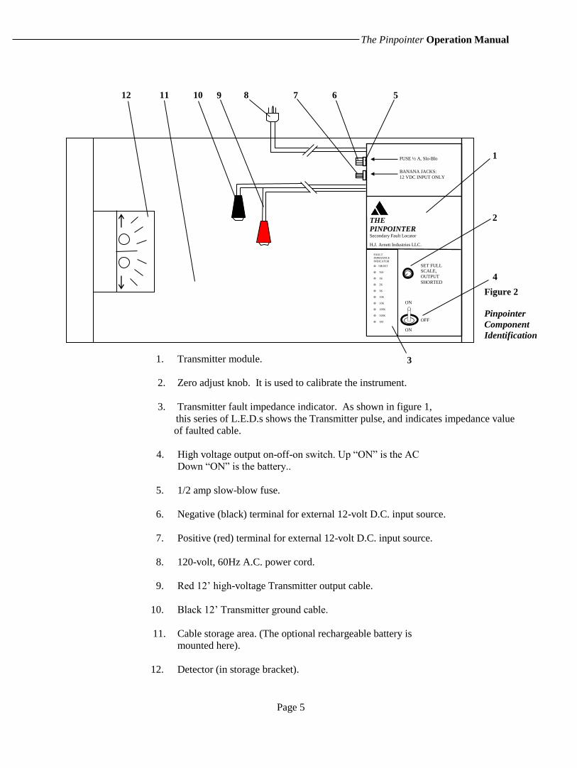
1. Transmitter module.
2. Zero adjust knob. It is used to calibrate the instrument.
3. Transmitter fault impedance indicator. As shown in figure 1,
this series of L.E.D.s shows the Transmitter pulse, and indicates impedance value
of faulted cable.
4. High voltage output on-off-on switch. Up “ON” is the AC
Down “ON” is the battery..
5. 1/2 amp slow-blow fuse.
6. Negative (black) terminal for external 12-volt D.C. input source.
7. Positive (red) terminal for external 12-volt D.C. input source.
8. 120-volt, 60Hz A.C. power cord.
9. Red 12’ high-voltage Transmitter output cable.
10. Black 12’ Transmitter ground cable.
11. Cable storage area. (The optional rechargeable battery is
mounted here).
12. Detector (in storage bracket).
FUSE ½ A, Slo-Blo
BANANA JACKS:
12 VDC INPUT ONLY
THE
PINPOINTER Secondary Fault Locator
H.J. Arnett Industries LLC.
ON
SET FULL
SCALE,
OUTPUT
SHORTED
1
Figure 2
Pinpointer
Component
Identification
3
2
4
12 11 10 9 8 7 6 5
ON OFF
FAULT
INPEDANCE
INDICATOR
O SHORT
O 500
O 1K
O 2K
O 5K
O 10K
O 50K
O 100K
O 500K
O 1M

Page 6
H. J. Arnett Industries, LLC
13. 3-foot A.C. adapter cord. Used to make 120VAC power
connection at meter base or at transformer.
14. 12-foot, 12VDC battery cable. Used ONLY to connect external
12-volt battery source – NOT FOR 120-VOLT USE!
15. Transmitter ground probe. For use with black Transmitter output cable to establish ground
connection.
16. Red & Black Detector probes with cables. These plug into the rear of Detector unit with attached
banana jacks.
17. Red & Black Detector probe extenders / handles.
13
14
Figure 3
Power
Cables
15
16
17
Black
White
Red
Black
Red
Black
Red
Black

Page 7
The Pinpointer Operation Manual
18. Top view of large 3½” zero-centered, quick-response D.C.
micro-ammeter. Fault direction is indicated by watching needle deflections
To the left or right. Also shows battery test.
19. Balance control/pull on-push off switch. Used to power up the
Detector and zero-balance the meter.
20. Sensitivity control. Best results are obtained when sensitivity
Is at lowest setting needed to display Transmitter pulses
satisfactorily.
21. Battery test switch. When pressed, needle on meter will
indicate if battery output is O.K.
22. Red & black Detector probe cable input terminals.
23. Side view of Detector housing. Removal of screws on each
side separates the halves of the housing, allowing access to
the 9-volt battery. Not shown: neck strap, which is secured to
the housing by these screws.
H.J. Arnett Industries, LLC.
BALANCE SENSITIVITY
PINPOINTER
DETECTOR
INCREASE PULL ON PUSH TO TEST
BATTERY
RED PROBE BLACK PROBE
H.J. ARNETT INDUSTRIES, LLC.
18
19
21
22
22
20
23
Figure 5
Pinpointer Detector
(Top, Bottom, and Side Views)
Note: Figures 2 through 5 not drawn to scale
Not shown is the tray, which holds the cables and probes.
BATT.
OK.
RED
PROBE BLACK
PROBE

Page 8
H. J. Arnett Industries, LLC.
II. Operation
A. General
Locating cable faults with the Pinpointer is simple. With the proper setup, and most
importantly, with the proper connection to ground, the Pinpointer will work every
time.
The Pinpointer is specially designed to eliminate or reduce false readings from
“phantom” or “ghost” faults. This design allows the Detector meter to remain “silent”
and not pulse until it is in the near vicinity of the fault. The needle will then show
pulses with increasing strength, directing the user quickly to the fault.
All secondary cable faults that are detectable by the earth gradient method can be
found using the Pinpointer, assuming proper connections are made by the operator.
This is due to the high-voltage (2500VDC) pulse emitted by the Transmitter which
burns to ground any secondary cable fault. The Transmitter then adjusts its output
according to the resistance of the fault, down to approximately 50VDC.
B. Transmitter Connections
IMPORTANT: ALWAYS WEAR RUBBER GLOVES
WHEN OPERATING THE PINPOINTER!
Whenever possible it is best to start at the house meter. With the Transmitter power
Switch OFF, connect the Pinpointer to a 120-volt A.C., 60Hz source, usually at the
meter. When using the 120VAC adapter cord, always connect the wire with white
insulator to system ground or neutral. The black wire is clipped to the hot leg.
If A.C. power is not available, connect the Pinpointer to a 12-volt D.C. external power
source. Every Pinpointer is supplied with a 12VDC battery cable for connection to a
truck battery. When the optional rechargeable battery is ordered, a cable is supplied
for connecting the battery to the 12VDC inputs. Always observe proper polarity!
C. Calibrating the Fault Impedance Indicator
The second step is to calibrate the fault impedance indicator. This step is not
necessary if you are not interested in knowing the approximate impedance of the
fault. Note that if there is voltage on the faulted cable, learning true impedance is not
possible.
To calibrate, short the red and black Transmitter output cables by clipping them
together. Turn on the Transmitter and adjust the potentiometer on the front panel
(labeled “Set full scale - output shorted”) so that the fault resistance indicator pulses
to the “SHORT” LED indicator for each Transmitter pulse.

Page 9
The Pinpointer Operation Manual
The Pinpointer is in effect a 2500-volt Megger, which will indicate the impedance of
the cable fault. This feature will tell you instantly if the cable is good or bad, as the
indicator will not pulse when it is connected to a good cable. It will also tell you
that the Transmitter is working properly.
.
D. Connecting to Faulted Cable and Ground
Isolate and de-energize cable when possible. Now connect the red Transmitter output cable to the faulted cable at the house
meter (see figure 6, below). Note that it is generally not necessary to disconnect
the faulted cable from the transformer except in cases explained below. Voltage
on a faulted secondary cable (90 volts or less) will not harm the Pinpointer.
NEVER CONNECT THE PINPOINTER TO A LIVE SECONDARY CABLE!
The next step is simple but very important -- success depends on the correctness
of this connection. Clip the Transmitter ground cable (black) to ground at the
meter box. In 95% of all cases this is all that is required to establish the proper
ground, but sometimes special techniques are needed. If you are unable to
locate the fault, we recommend to try the following:
1. Establish your own ground. Remove neutral from system
ground at both ends, especially if neutral is bare copper.
Disconnect any temporary service to house. Push the ground
probe provided with the Pinpointer into the ground at a right
angle to and as far away as possible from the faulted cable.
The black Transmitter ground cable is 12’ in length and should
provide enough distance from the faulted cable to be effective.
Connect this cable to the ground probe. If this procedure does
not help locate the fault, try moving the ground probe to
Pinpointer I
Transmitter
Black
Red Transmitter
Output
Fault Figure 6
Typical Pinpointer I
Connections
Power Cord 120 VAC Input
Meter
Socket

Page 10
H. J. Arnett Industries, LLC.
different locations and repeat the locating procedure. Note
that this setup is always necessary when locating a fault on a
primary cable.
2. Disconnect energized cables. Disconnect the faulted cable
from the transformer if the voltage on the cable is 90 volts or
more. Especially in cases where the fault is high impedance
and is buried in very dry soil or under pavement, the
reduced voltage on the cable may be too much for the pulse to
push against. Again, the thought here is to isolate the cable
from as many external influences as possible, so remember to
isolate, isolate, isolate!
3. Transmitter from the other end of the cable. Go to the far end of
the cable, connect the Transmitter, and repeat the entire
process from that end. If your cannot find the fault from one end of the cable,
go to the other.
The emphasis here is that successful fault locating depends on establishing
a good, correct local ground. Most of the time connecting onto the neutral does
the job. But when a high-impedance fault is located in high dielectric soil (dry and
sandy), is under cement or asphalt, or is in an area crowded with bare conductors,
pipes and grounds, all other grounds must be removed from the faulted cable. This
ensures that the local ground you establish with the probe is the shortest, lowest
impedance return path for the Transmitter's pulse. The Pinpointer will always
locate the fault with the proper ground.
When more than one customer is served on the same cable from the transformer,
connect the Pinpointer to the first meter past the fault. Pull all other meters, if any,
past the fault, as shown below in figure 7.
After these connections are made, turn on the high-voltage output on the
Transmitter. The unit will begin to emit a 2500-volt pulse every 3 to 4 seconds.
Primary
Figure 7
Connection With
Multiple Meters
1
3
2
4
Meter
Meter
Meter
Meter
Remove
this meter Fault
Pinpointer I
Page 11
The Pinpointer Operation Manual
E. Detector Connections
Remove the Detector from its bracket in the Pinpointer case. Pull out on the balance
control knob to power up the Detector. With the sensitivity control at its lowest
setting, adjust the balance control until the meter needle is centered on the scale
(see figure 5 for reference). Plug the red and black Detector probe cables into their
respective jacks at the rear of the Detector unit. Note that it is important to keep
these banana jacks clean for maximum Detector sensitivity!
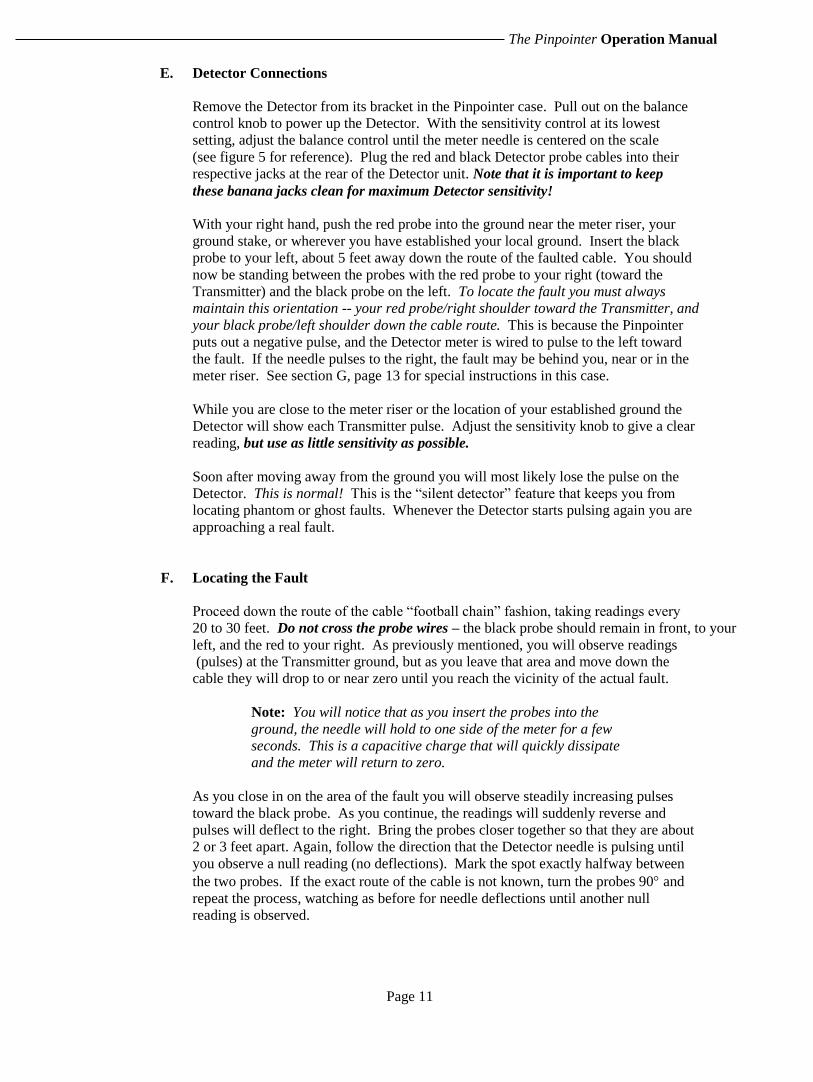
With your right hand, push the red probe into the ground near the meter riser, your
ground stake, or wherever you have established your local ground. Insert the black
probe to your left, about 5 feet away down the route of the faulted cable. You should
now be standing between the probes with the red probe to your right (toward the
Transmitter) and the black probe on the left. To locate the fault you must always
maintain this orientation -- your red probe/right shoulder toward the Transmitter, and
your black probe/left shoulder down the cable route. This is because the Pinpointer
puts out a negative pulse, and the Detector meter is wired to pulse to the left toward
the fault. If the needle pulses to the right, the fault may be behind you, near or in the
meter riser. See section G, page 13 for special instructions in this case.
While you are close to the meter riser or the location of your established ground the
Detector will show each Transmitter pulse. Adjust the sensitivity knob to give a clear
reading, but use as little sensitivity as possible.
Soon after moving away from the ground you will most likely lose the pulse on the
Detector. This is normal! This is the “silent detector” feature that keeps you from
locating phantom or ghost faults. Whenever the Detector starts pulsing again you are
approaching a real fault.
F. Locating the Fault
Proceed down the route of the cable “football chain” fashion, taking readings every
20 to 30 feet. Do not cross the probe wires – the black probe should remain in front, to your
left, and the red to your right. As previously mentioned, you will observe readings
(pulses) at the Transmitter ground, but as you leave that area and move down the
cable they will drop to or near zero until you reach the vicinity of the actual fault.
Note: You will notice that as you insert the probes into the
ground, the needle will hold to one side of the meter for a few
seconds. This is a capacitive charge that will quickly dissipate
and the meter will return to zero.
As you close in on the area of the fault you will observe steadily increasing pulses
toward the black probe. As you continue, the readings will suddenly reverse and
pulses will deflect to the right. Bring the probes closer together so that they are about
2 or 3 feet apart. Again, follow the direction that the Detector needle is pulsing until
you observe a null reading (no deflections). Mark the spot exactly halfway between
the two probes. If the exact route of the cable is not known, turn the probes 90 and
repeat the process, watching as before for needle deflections until another null
reading is observed.

Page 12
H. J. Arnett Industries, LLC.
Where the two null marks intersect is the cable fault! (See figures 8 and 9, below)
Mark
this spot Figure 8
Meter
Deflection
Examples
To Transformer From Meter
Fault
Detector Usage Tips
1. Remove hand from probe after
inserting it into the ground, as it
disturbs the Detector meter.
2. In rocky or frozen ground, on cement
or blacktop, or in any area where it is
too hard to insert the probes, we
suggest the following:
a. Gather 2 rectangular sponges, a
plastic bucket, and a bag of rock
salt. Dissolve approximately 1/2
cup of table salt in 1 gallon
of water. Soak the sponges
thoroughly. Stick the Detector
probes through the sponges so
they can lay flat on the ground
and proceed as usual. Resoak
the sponges often.
b. If wet sponges are not available,
try using copper or aluminum
plates, about 4x8 inches in size
Drill holes in the plates to accept
the tips of the probes. The plate
is not as good as the sponge, but
either method works well when
needed.
Pulses Toward
Red Probe
Black
Probe
Pulses Toward
Black Probe
Red
Probe
Null
Ground
Line
Maximum
pulse at fault
is about the
same size as
that observed
at meter riser
Red Probe
Pulses Toward
Black Probe
Null Point From Meter
Pulses Toward
Red Probe
Black Probe
This Operation
may be bypassed if
exact cable route
is know
Figure 9
Confirming
Location When
Cable Route is
Unknown
To Transformer
Page 13
The Pinpointer Operation Manual
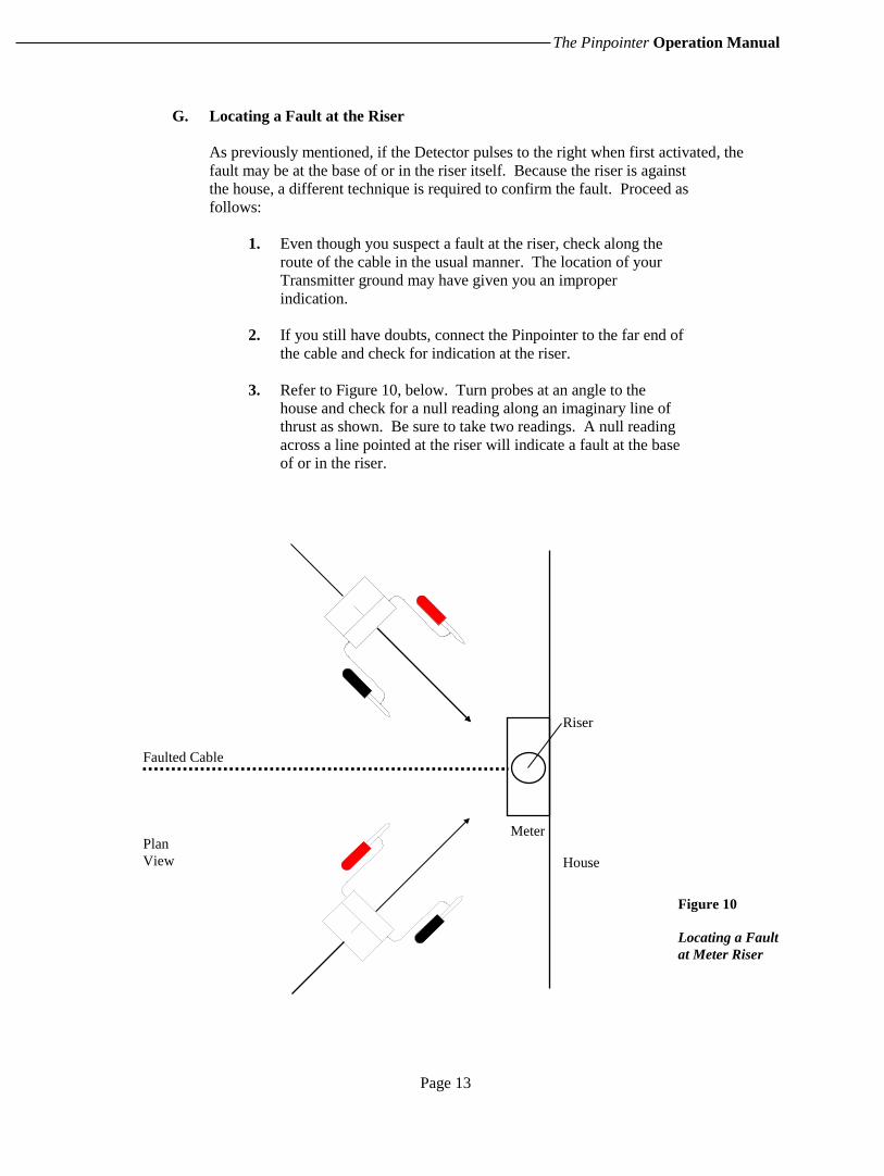
G. Locating a Fault at the Riser
As previously mentioned, if the Detector pulses to the right when first activated, the
fault may be at the base of or in the riser itself. Because the riser is against
the house, a different technique is required to confirm the fault. Proceed as
follows:
1. Even though you suspect a fault at the riser, check along the
route of the cable in the usual manner. The location of your
Transmitter ground may have given you an improper
indication.
2. If you still have doubts, connect the Pinpointer to the far end of
the cable and check for indication at the riser.
3. Refer to Figure 10, below. Turn probes at an angle to the
house and check for a null reading along an imaginary line of
thrust as shown. Be sure to take two readings. A null reading
across a line pointed at the riser will indicate a fault at the base
of or in the riser.
Faulted Cable
Riser
Figure 10
Locating a Fault
at Meter Riser
Plan
View House
Meter
Page 14
H. J. Arnett Industries, LLC.
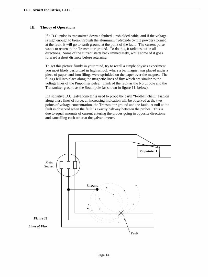
III. Theory of Operations
If a D.C. pulse is transmitted down a faulted, unshielded cable, and if the voltage
is high enough to break through the aluminum hydroxide (white powder) formed
at the fault, it will go to earth ground at the point of the fault. The current pulse
wants to return to the Transmitter ground. To do this, it radiates out in all
directions. Some of the current starts back immediately, while some of it goes
forward a short distance before returning.
To get this picture firmly in your mind, try to recall a simple physics experiment
you most likely performed in high school, where a bar magnet was placed under a
piece of paper, and iron filings were sprinkled on the paper over the magnet. The
filings fell into place along the magnetic lines of flux which are similar to the
voltage lines of the Pinpointer pulse. Think of the fault as the North pole and the
Transmitter ground as the South pole (as shown in figure 11, below).
If a sensitive D.C. galvanometer is used to probe the earth “football chain” fashion
along these lines of force, an increasing indication will be observed at the two
points of voltage concentration, the Transmitter ground and the fault. A null at the
fault is observed when the fault is exactly halfway between the probes. This is
due to equal amounts of current entering the probes going in opposite directions
and cancelling each other at the galvanometer.
Meter
Socket
Pinpointer I
Fault
Figure 11
Lines of Flux
Ground
Page 15
The Pinpointer Operation Manual
IV. Optional Rechargeable 12-Volt Battery Kit Instructions
A. Charging the Rechargeable Battery
It is a good idea to charge the battery before initial use with The Pinpointer.
To charge the battery:
1)Disconnect any cables from the battery.
2) Connect the red and black leads from the battery charger to the
battery. Pay strict attention to the colors: always connect red to
red and black to black.
3) The battery charger is fully automatic. The bi-color LED will let
you know the condition of the battery if the LED is red AC is
connected and battery is fast charging. If the LED is green then
AC is connected and battery is fully charged.
4) The battery will recharge overnight if slightly discharged, or
within 24 hours if very discharged. When the charging cycle is
complete, the green LED will be on.
5) Caution: If the LED remains red for more than 24 hours, unplug
the charger from AC power and check the battery. There may be
a problem with the battery.
B. Notes
Normally the battery will last through one job. When coming in from a job, plug the
battery into the charger for an overnight recharge. This assures a charged battery for
the next job.
The battery can be left on the charger for up to 48 hours. Additional time will not
result in additional charge so the charger should be disconnected after 48 hours. The
charger limits charging current, however, the battery is never overcharged.
The battery is fully charged when its terminal voltage has reached 13.3 to 13.4 volts.
It should be recharged when the terminal voltage drops below 11.5 volts.
A new battery has an Ah rating of 7.0 Amp-hours.
Page 16
H. J. Arnett Industries, LLC.
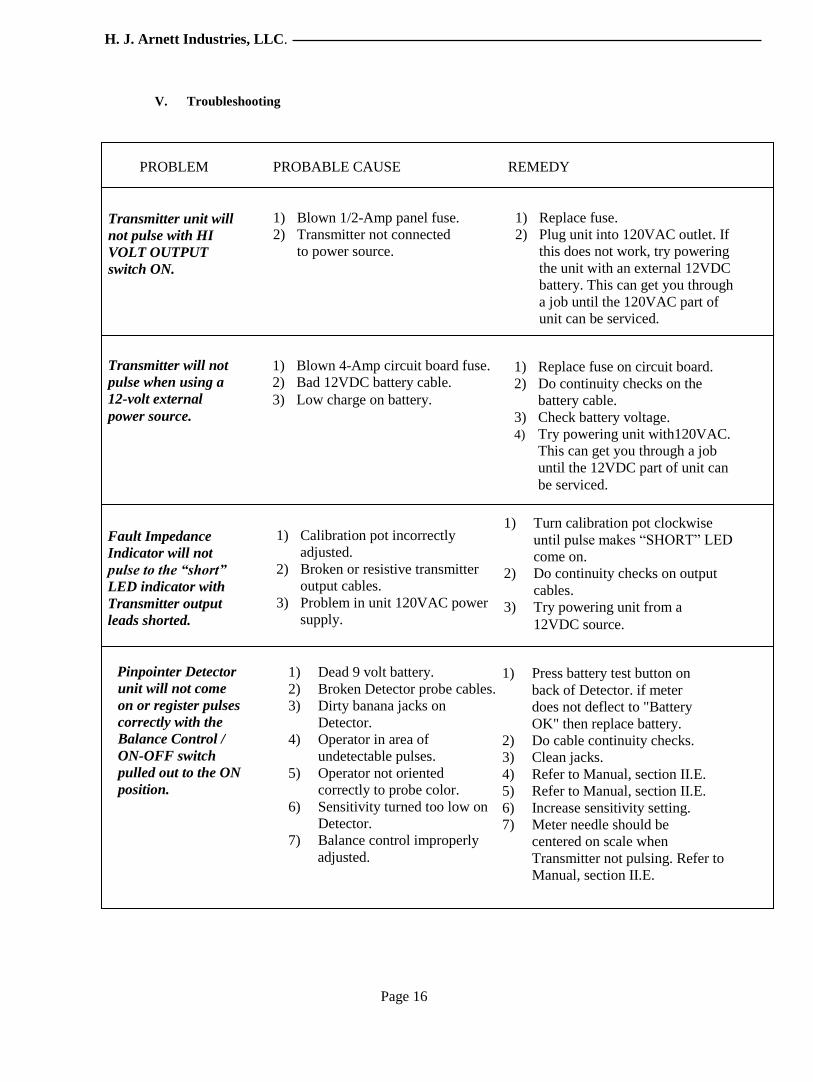
V. Troubleshooting
Transmitter unit will
not pulse with HI
VOLT OUTPUT
switch ON.
1) Blown 1/2-Amp panel fuse.
2) Transmitter not connected
to power source.
1) Replace fuse.
2) Plug unit into 120VAC outlet. If
this does not work, try powering
the unit with an external 12VDC
battery. This can get you through
a job until the 120VAC part of
unit can be serviced.
1) Replace fuse on circuit board.
2) Do continuity checks on the
battery cable.
3) Check battery voltage.
4) Try powering unit with120VAC.
This can get you through a job
until the 12VDC part of unit can
be serviced.
1) Blown 4-Amp circuit board fuse.
2) Bad 12VDC battery cable.
3) Low charge on battery.
Transmitter will not
pulse when using a
12-volt external
power source.
1) Turn calibration pot clockwise
until pulse makes “SHORT” LED
come on.
2) Do continuity checks on output
cables.
3) Try powering unit from a
12VDC source.
1) Calibration pot incorrectly
adjusted.
2) Broken or resistive transmitter
output cables.
3) Problem in unit 120VAC power
supply.
Fault Impedance
Indicator will not
pulse to the “short”
LED indicator with
Transmitter output
leads shorted.
1) Press battery test button on
back of Detector. if meter
does not deflect to "Battery
OK" then replace battery.
2) Do cable continuity checks.
3) Clean jacks.
4) Refer to Manual, section II.E.
5) Refer to Manual, section II.E.
6) Increase sensitivity setting.
7) Meter needle should be
centered on scale when
Transmitter not pulsing. Refer to
Manual, section II.E.
1) Dead 9 volt battery.
2) Broken Detector probe cables.
3) Dirty banana jacks on
Detector.
4) Operator in area of
undetectable pulses.
5) Operator not oriented
correctly to probe color.
6) Sensitivity turned too low on
Detector.
7) Balance control improperly
adjusted.
Pinpointer Detector
unit will not come
on or register pulses
correctly with the
Balance Control /
ON-OFF switch
pulled out to the ON
position.
PROBLEM PROBABLE CAUSE REMEDY

Page 17
The Pinpointer Operation Manual
VI. Parts List
HJA-470 The Pinpointer complete.
HJA-470-109 Optional Rechargeable Battery Kit. Includes 12-volt
D.C., 7.0-AH rechargeable battery, recharger unit,
cables, mounting bracket and hardware.
470-100 Detector unit, complete. Includes 9-volt battery.
470-101-HDPR Detector probe, red.
470-101 -HDPB Detector probe, black.
470-101-HDE Detector probe extender, red.
470-101-HDE Detector probe extender, black.
470-102 Transmitter module. Includes power and high-voltage cables.
470-206 Transmitter ground probe.
470-104 12VDC battery cable.
470-105 120VAC adapter cord.
470-106 Equipment carrying case, with labels and Detector bracket.
470-100-MAN Pinpointer Operations Manual.
470-208-A 12-volt D.C., 7.0-AH rechargeable battery.
470-209-B 12-volt battery Recharger unit, complete.
IMPORTANT NOTE: The Pinpointer Transmitter and Detector have no user-serviceable
parts inside, except as outlined in this manual. Please return the complete Pinpointer to
H.J. Arnett LLC. or qualified personnel when service is required.

Page 18
H. J. Arnett Industries, LLC.
VII. Specifications
Transmitter
Power requirements:
120VAC @ 60 Watts - pulsing A.C. protected with 1/2-Amp, slo-blow, and panel
@ 15 Watts - normal mounted fuse.
12VDC @ 10 Watts-pulsing 12VDC inputs protected with circuit board
@ 0.5 Watts - normal mounted 4-Amp fuse.
Output voltage 2300-2500VDC typical, across 10-megohm load.
50VDC typical, across 625-ohm load.
Output pulse rate One pulse every 3 to 4 seconds.
Output pulse duration Approximately 200 milliseconds, typical.
Fault Impedance Indicator This indicator not intended to give an accurate
representation of fault impedance. It does,
however, give an “idea” of what the fault
impedance is.
Detector (Galvanometer)
9VDC, transistor battery powered Battery test feature shows if battery is good on
Detector meter. Battery is easily user-replaceable.
Taut-band, zero-center 3½” meter Large, quick-response meter guides user to cable
fault quickly.
Meter sensitivity & balance Allows user to fine-tune operation of Detector.
adjustments
Dimensions 20” L x 8” W x 9” H
Weight 18 lbs. net
21 lbs. shipping

Page 19
Warranty And Limitation
Parts and labor are guaranteed for one year from date of purchase. Any return is subject to a
restocking charge and must be accompanied by a Return Authorization.
All statements, technical information and recommendations contained herein are based on tests we believe to
be reliable, but the accuracy or completeness thereof is not guaranteed, and the following is made in lieu of all
warranties, express or implied: Seller’s and manufacturer’s only obligation shall be to replace such quantity of
the product proved to be defective. Neither seller nor manufacturer shall be liable for any injury, loss or
damage, direct or consequential, arising out of the use of or the inability to use the product. Before using, user
assumes all risk and liability whatsoever in connection therewith. No statement or recommendation not
contained herein shall have any force or effect unless in an agreement signed by officers of seller or
manufacturer.
To order parts or for assistance, call or email:
H.J Arnett Industries, L.L.C.
20460 Avery Court
Tualatin, OR 97062
Phone (503) 692-4600 -- Fax (503) 692-4661
Hjarnett.com