the reference about rhino xr robot system ece565 …web.cecs.pdx.edu/~mperkows/class_479/psubot2/1....
TRANSCRIPT

The Reference about Rhino XR Robot SystemECE565 Robotics class
Version 2.0
Written by : SeungJoon Choimailto:[email protected]
March 28, 2002
c�This document is not freely distributable. Please let me know.
Contents1 Rhino Robot System : Overview 2
1.1 XR-3 Robotic Arm . . . . . . . . . . . . . . . . . . . . . . . . . . . . . . . . . . . . . . . 21.2 MARK III Controller . . . . . . . . . . . . . . . . . . . . . . . . . . . . . . . . . . . . . . 21.3 Teach pendant . . . . . . . . . . . . . . . . . . . . . . . . . . . . . . . . . . . . . . . . . . 5
2 Specifications of Rhino XR System 52.1 Basic dimensions . . . . . . . . . . . . . . . . . . . . . . . . . . . . . . . . . . . . . . . . 62.2 Servo . . . . . . . . . . . . . . . . . . . . . . . . . . . . . . . . . . . . . . . . . . . . . . 62.3 Encoder . . . . . . . . . . . . . . . . . . . . . . . . . . . . . . . . . . . . . . . . . . . . . 82.4 Optics . . . . . . . . . . . . . . . . . . . . . . . . . . . . . . . . . . . . . . . . . . . . . . 92.5 Interface . . . . . . . . . . . . . . . . . . . . . . . . . . . . . . . . . . . . . . . . . . . . . 10
3 Teach pendant operation 103.1 Home position . . . . . . . . . . . . . . . . . . . . . . . . . . . . . . . . . . . . . . . . . . 103.2 Motion keys . . . . . . . . . . . . . . . . . . . . . . . . . . . . . . . . . . . . . . . . . . . 12
4 Control and Programming 124.1 <return> Initiate a motor move . . . . . . . . . . . . . . . . 144.2 ? Question command . . . . . . . . . . . . . . . . . . . 144.3 A to H start motor commands . . . . . . . . . . . . . . . . 154.4 I I-Inquiry command . . . . . . . . . . . . . . . . . . . 154.5 J J-Inquiry command . . . . . . . . . . . . . . . . . . . 164.6 K K-INQUIRY command . . . . . . . . . . . . . . . . . 174.7 L Turn Aux. Port#1 ON . . . . . . . . . . . . . . . . . . 184.8 M Turns Aux. Port#1 OFF . . . . . . . . . . . . . . . . . 184.9 N Turns AuX. port#2 ON . . . . . . . . . . . . . . . . . . 184.10 O Turns Aux. Port#2 OFF . . . . . . . . . . . . . . . . . 194.11 P set output Line High . . . . . . . . . . . . . . . . . . 194.12 Q Reset . . . . . . . . . . . . . . . . . . . . . . 19
1

ECE565 Robotics - CONTENTS 2
4.13 R set output Line Low . . . . . . . . . . . . . . . . . . 194.14 X Stop motor command . . . . . . . . . . . . . . . . . . 20
5 Simulator : SIMULATR 20
POSTECH ECE Control Lab., Eng. Bldg. 2-408
ECE565 Robotics - 1 RHINO ROBOT SYSTEM : OVERVIEW 3
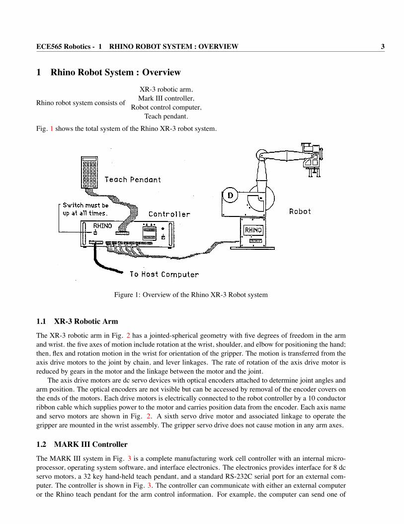
1 Rhino Robot System : Overview
Rhino robot system consists of
XR-3 robotic arm,Mark III controller,
Robot control computer,Teach pendant.
Fig. 1 shows the total system of the Rhino XR-3 robot system.
Figure 1: Overview of the Rhino XR-3 Robot system
1.1 XR-3 Robotic Arm
The XR-3 robotic arm in Fig. 2 has a jointed-spherical geometry with five degrees of freedom in the armand wrist. the five axes of motion include rotation at the wrist, shoulder, and elbow for positioning the hand;then, flex and rotation motion in the wrist for orientation of the gripper. The motion is transferred from theaxis drive motors to the joint by chain, and lever linkages. The rate of rotation of the axis drive motor isreduced by gears in the motor and the linkage between the motor and the joint.
The axis drive motors are dc servo devices with optical encoders attached to determine joint angles andarm position. The optical encoders are not visible but can be accessed by removal of the encoder covers onthe ends of the motors. Each drive motors is electrically connected to the robot controller by a 10 conductorribbon cable which supplies power to the motor and carries position data from the encoder. Each axis nameand servo motors are shown in Fig. 2. A sixth servo drive motor and associated linkage to operate thegripper are mounted in the wrist assembly. The gripper servo drive does not cause motion in any arm axes.
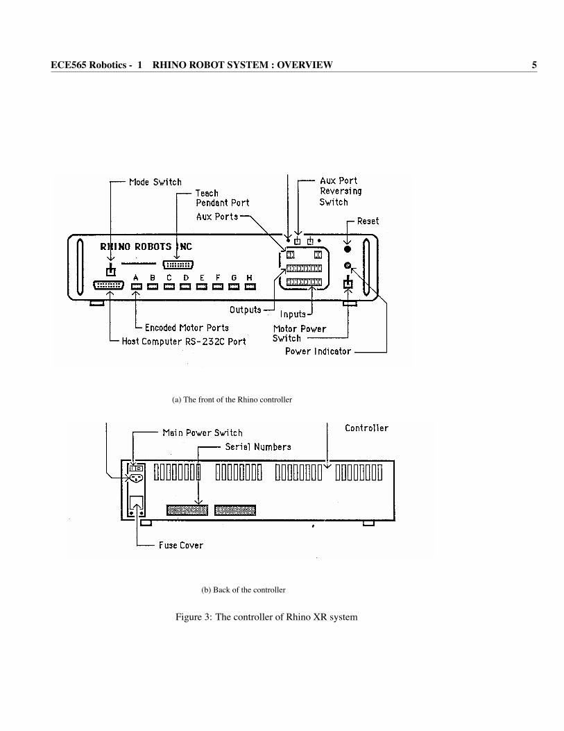
1.2 MARK III Controller
The MARK III system in Fig. 3 is a complete manufacturing work cell controller with an internal micro-processor, operating system software, and interface electronics. The electronics provides interface for 8 dcservo motors, a 32 key hand-held teach pendant, and a standard RS-232C serial port for an external com-puter. The controller is shown in Fig. 3. The controller can communicate with either an external computeror the Rhino teach pendant for the arm control information. For example, the computer can send one of
POSTECH ECE Control Lab., Eng. Bldg. 2-408

ECE565 Robotics - 1 RHINO ROBOT SYSTEM : OVERVIEW 4
Figure 2: Joint and Servo motor name
POSTECH ECE Control Lab., Eng. Bldg. 2-408
ECE565 Robotics - 1 RHINO ROBOT SYSTEM : OVERVIEW 5
(a) The front of the Rhino controller
(b) Back of the controller
Figure 3: The controller of Rhino XR system
POSTECH ECE Control Lab., Eng. Bldg. 2-408

ECE565 Robotics - 2 SPECIFICATIONS OF RHINO XR SYSTEM 6
the 13 work cell and robot commands to the controller over the RS-232C serial port. When the controllerreceives the command from the computer, the microprocessor inside the controller executes the command.The serial port and the commands included in the operating system software in the controller permit robotand work cell control from a remote computer. Using the same technique, the Rhino teach pendant can beused to control robot motion and develop work cell programs.
The controller has a MODE SELECT switch to put controller in either the teach pendant or remotecomputer mode. Two power switch allow separate control of the main power and servo motor power. Apush button, labeled RESET, reestablishes the initial values in the controller memory and operating system.Also, the reset button on both the controller and the teach pendant are your EMERGENCY stopbuttons. A pilot map on the front panel indicates when the main power switch is in the “on” position.
The pendant is a 32 key microprocessor controlled programming unit with a 7 character digital displayand a reset button to restart the controller and act as an emergency stop.
If you do experiment with Rhino robot system. Please do first below in order.
• Check Motor Power switch is off.
• Turn on main controller power - Main power switch is at rear panel of the controller. (Fig. 3(b))
• Check the Motor Switch.
• Turn on the motor power switch.
• Push reset switch.
• Check ‘init’ is displayed in Teach pendant 7-segment LED panel.And the power down sequence is the reverse of the power-up order. Use the following sequence to take theRhino work cell in the teach pendant programming mode out of service.
1. Turn “off” arm motor power.
2. Turn controller power “off”.
3. Turn the computer “off”.
1.3 Teach pendant
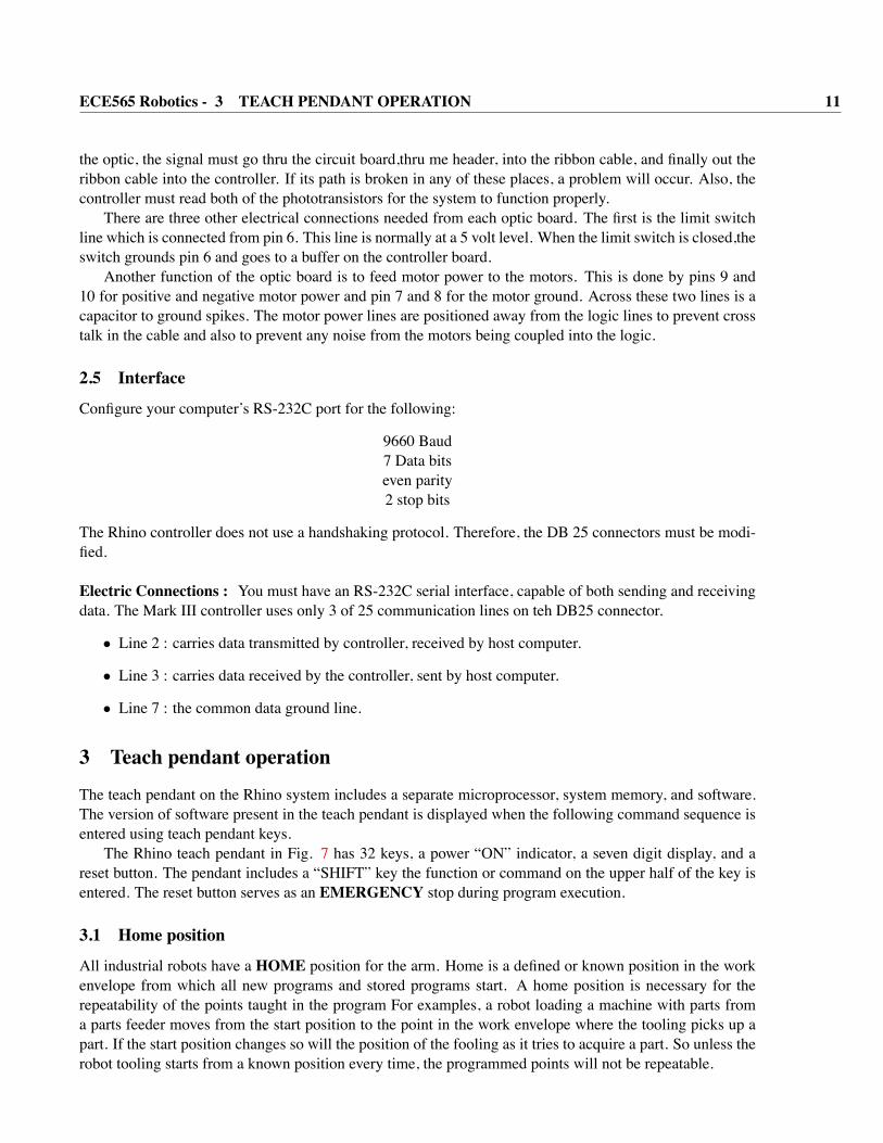
The Rhino robot system has both a teach terminal and a teach pendant to program the robot arm and workcell hardware. The Rhino XR-3 teach pendant, illustrated in Fig. 7, is connected to the MARK III by aribbon cable and connector on the front panel of the controller. The pendant is a 32 key microprocessorcontrolled programming unit with a 7 character digital display and a reset button to restart the controllerand act as an emergency stop. Fifteen of the keys are used for program development and 16 provide motioncontrol for the 5 arm axis servos, gripper servo, and 2 auxiliary servos. The teach pendant supports workcell program development in two ways: 1. complete work cell programs can be generated using only theteach pendant keys, 2. arm positions for programs written on the teach pendant terminal are taught using theteach pendant.
The teach pendant, the microcomputer in a Rhino robot system, is connected to the MARK III controllerthrough the RS-232C serial port.
2 Specifications of Rhino XR SystemIn this section, specification of the Rhino XR system is presented. And, some components of the Rhinorobot system are also explained.
POSTECH ECE Control Lab., Eng. Bldg. 2-408
ECE565 Robotics - 2 SPECIFICATIONS OF RHINO XR SYSTEM 7
2.1 Basic dimensions
This is the Rhino system in a nutshell. The following tables give the specifications for the Rhino system.
• Basic specifications for the Rhino robot arm
– Vertical Reach : 68cm– Radical Reach : 60cm– Lifting Capability ( arm extended ) : 0.45Kg– Weight of Rhino : 7.7Kg– Weight of Controller : 12.3Kg
• Resolution at each axis
Axis Motor ResolutionFingers A not applicable
Wrist Rotation B 0.18 degrees theoreticalWrist Flex C 0.12 degrees theoreticalForearm D 0.12 degrees theoreticalShoulder E 0.12 degrees theoreticalWaist F 0.23 degrees theoretical
• Motor gear ratios and final reductions
Axis Motor Gear Ratio Encoder stepsFingers 96/1 not applicable
Wrist Rotation 165.4/1 5.5lWrist Flex 66.1/1 8.8Elbow 66.1/1 8.8Shoulder 66.1/1 8.8Waist 66.1/1 4.4
• Speed at each axis
Axis Speed(degrees/second)Fingers 1 sec. to open and close fully
Wrist Rotation 32Wrist Flex 45Elbow 30Shoulder 20Waist 60
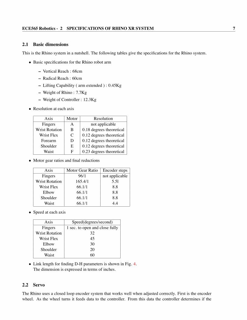
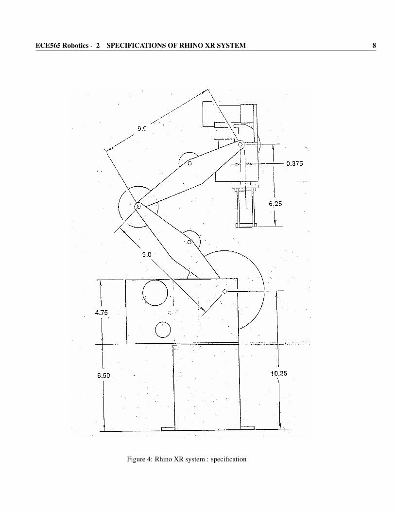
• Link length for finding D-H parameters is shown in Fig. 4.The dimension is expressed in terms of inches.
2.2 Servo
The Rhino uses a closed loop encoder system that works well when adjusted correctly. First is the encoderwheel. As the wheel turns it feeds data to the controller. From this data the controller determines if the
POSTECH ECE Control Lab., Eng. Bldg. 2-408
ECE565 Robotics - 2 SPECIFICATIONS OF RHINO XR SYSTEM 8
Figure 4: Rhino XR system : specification
POSTECH ECE Control Lab., Eng. Bldg. 2-408
ECE565 Robotics - 2 SPECIFICATIONS OF RHINO XR SYSTEM 9
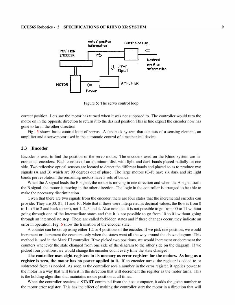
Figure 5: The servo control loop
correct position. Lets say the motor has turned when it was not supposed to. The controller would turn themotor on in the opposite direction to return it to the desired position This is fine expect the encoder now hasgone to far in the other direction.
Fig. 5 shows basic control loop of servos. A feedback system that consists of a sensing element, anamplifier and a servomotor used in the automatic control of a mechanical device.
2.3 Encoder
Encoder is used to find the position of the servo motor. The encoders used on the Rhino system are in-cremental encoders. Each consists of an aluminum disk with light and dark bands placed radially on oneside. Two reflective optical sensors are located to detect the different bands and placed so as to produce twosignals (A and B) which are 90 degrees out of phase. The large motors (C-F) have six dark and six lightbands per revolution; the remaining motors have 3 sets of bands.
When the A signal leads the B signal, the motor is moving in one direction and when the A signal trailsthe B signal, the motor is moving in the other direction. The logic in the controller is arranged to be able tomake the necessary discrimination.
Given that there are two signals from the encoder, there are four states that the incremental encoder canprovide. They are 00, 01, 11 and 10. Note that if these were interpreted as decimal values, the flow is from 0to 1 to 3 to 2 and back to zero, not 1, 2, 3 and 4. Also note that it is not possible to go from 00 to 11 withoutgoing through one of the intermediate states and that it is not possible to go from 10 to 01 without goingthrough an intermediate step. These are called forbidden states and if these changes occur, they indicate anerror in operation. Fig. 6 show the transition of the encoder state.
A counter can be set up using either 1,2 or 4 positions of the encoder. If we pick one position, we wouldincrement or decrement the counters only when the states went all the way around the above diagram. Thismethod is used in the Mark III controller. If we picked two positions, we would increment or decrement thecounters whenever the state changed from one side of the diagram to the other side on the diagram. If wepicked four positions, we would change the encoder count every time the state changed.The controller uses eight registers in its memory as error registers for the motors. As long as a
register is zero, the motor has no power applied to it. If an encoder turns, the register is added to orsubtracted from as needed. As soon as the controller sees a number in the error register, it applies power tothe motor in a way that will turn it in the direction that will decrement the register as the motor turns. Thisis the holding algorithm that maintains motor position at all times.
When the controller receives a START command from the host computer, it adds the given number tothe motor error register. This has the effect of making the controller start the motor in a direction that will
POSTECH ECE Control Lab., Eng. Bldg. 2-408

ECE565 Robotics - 2 SPECIFICATIONS OF RHINO XR SYSTEM 10
Figure 6: Encoder states
make that error register go to zero. Each cycle of the encoder changes the error register by one. When theerror hoes to zero, the motor is turned off. If the motor overshoots, the power to the motor will be reversedautomatically to bring the motor back to the zero position.
With the Rhino XR-3 robot, the large motors have 6 detectable state per motor revolution and the smallmotors have 3 states per revolution.
2.4 Optics
The optics system is the electronic circuitry that feeds;information back to me controller with regard to meposition of the motor. The information needed by the controller is the position of the motor and the status ofthe microswitch. There are a few key assemblies used in the optics system to perform these functions. Theyfollow, and each is very necessary to have the robot function correctly.
1. Optics board assembly
2. Encoder wheel assembly
3. Ribbon cable assembly
Optic Board Assembly
The Optic printed circuit board includes 2 infra-red LEDs, 2 infra-red Phototransistors,biasing resistors,a cable header, and an mounting bracket. There are two types of assemblies used with the XR-3 robot. Theyare exactly the same except they use different mounting1 brackets. The three hole bracket is for the smallmotors in the hand. The body brackets seem to have 2, 4, or 6 hole types. The cable header is a ten pin maleheader used to connect the ribbon cable into the optic board. The biasing resistors are used to determine thecurrent that is allowed to go through the LEDs and the phototransistors. The optics printed circuit board isused to mount all of the components and provide electrical connections needed.
The LEDs are infra red so you cannot see the light. However the light is quite bright and is on any time5 Volts is applied to the circuit board. The light is directed out of the LEDs towards the phototransistors.This will turn the phototransistor on. The phototransistors are turned off when they cannot see the infra redlight. This condition occurs when the encoder wheel is between the LED and the phototransistor and theydo not line up with one of the slots in the wheel. This prevents the infra red light from getting through.
As soon as the phototransistor sees infra red light,the base region of the phototransistor saturates, allow-ing current to flow thru the device. The collector drops from 4.80 volts to .70 volts. This change of state isnoticed by the controller, which is constantly monitoring the optics. In order for the controller to monitor
POSTECH ECE Control Lab., Eng. Bldg. 2-408
ECE565 Robotics - 3 TEACH PENDANT OPERATION 11
the optic, the signal must go thru the circuit board,thru me header, into the ribbon cable, and finally out theribbon cable into the controller. If its path is broken in any of these places, a problem will occur. Also, thecontroller must read both of the phototransistors for the system to function properly.
There are three other electrical connections needed from each optic board. The first is the limit switchline which is connected from pin 6. This line is normally at a 5 volt level. When the limit switch is closed,theswitch grounds pin 6 and goes to a buffer on the controller board.
Another function of the optic board is to feed motor power to the motors. This is done by pins 9 and10 for positive and negative motor power and pin 7 and 8 for the motor ground. Across these two lines is acapacitor to ground spikes. The motor power lines are positioned away from the logic lines to prevent crosstalk in the cable and also to prevent any noise from the motors being coupled into the logic.
2.5 Interface
Configure your computer’s RS-232C port for the following:
9660 Baud7 Data bitseven parity2 stop bits
The Rhino controller does not use a handshaking protocol. Therefore, the DB 25 connectors must be modi-fied.
Electric Connections : You must have an RS-232C serial interface, capable of both sending and receivingdata. The Mark III controller uses only 3 of 25 communication lines on teh DB25 connector.
• Line 2 : carries data transmitted by controller, received by host computer.
• Line 3 : carries data received by the controller, sent by host computer.
• Line 7 : the common data ground line.
3 Teach pendant operationThe teach pendant on the Rhino system includes a separate microprocessor, system memory, and software.The version of software present in the teach pendant is displayed when the following command sequence isentered using teach pendant keys.
The Rhino teach pendant in Fig. 7 has 32 keys, a power “ON” indicator, a seven digit display, and areset button. The pendant includes a “SHIFT” key the function or command on the upper half of the key isentered. The reset button serves as an EMERGENCY stop during program execution.
3.1 Home position
All industrial robots have a HOME position for the arm. Home is a defined or known position in the workenvelope from which all new programs and stored programs start. A home position is necessary for therepeatability of the points taught in the program For examples, a robot loading a machine with parts froma parts feeder moves from the start position to the point in the work envelope where the tooling picks up apart. If the start position changes so will the position of the fooling as it tries to acquire a part. So unless therobot tooling starts from a known position every time, the programmed points will not be repeatable.
POSTECH ECE Control Lab., Eng. Bldg. 2-408
ECE565 Robotics - 3 TEACH PENDANT OPERATION 12
Figure 7: Rhino XR system teach pendant
POSTECH ECE Control Lab., Eng. Bldg. 2-408

ECE565 Robotics - 4 CONTROL AND PROGRAMMING 13
The Cincinnati Milacron family of robots has a single home position which must be taught during thepower-up sequence using the command “Home, Set”. The Rhino system has two types of HOME positions.The HARD HOME is a mechanical home position which is determined by limit switches located on thewaist, shoulder, elbow, wrist flex, and wrist rotate axes. The SOFT HOME is a software home and can beset at any position in the work envelope. Hard home must be performed before a new move sequence istaught and before a stored sequence is loaded and executed. The soft home position is a point in the workenvelope selected by the programmer because it is an efficient starting point for the desired move sequence.The hard home command command is that holding the SHIFT down while the function key is pressedcauses the function described in the upper block of the key to be initiated. The function in the bottom blockis activated without the SHIFT key. At this case you may see ”PGoHArd” in LCD panel.
3.2 Motion keys
The position axes are waist, shoulder, and elbow, while the orientation axes include the two wrist motionsflex and rotation. In addition, the gripper open and close control is part of the motion key group on the Rhinopendant.SYSTEM RESPONSE : When any of the axis motion keys, A through H, are pressed the axis motor
moves 10 increments on the optical encoder which is about 1.2 degrees for the position axes. Each axishas a key for either the positive or negative direction. The teach pendant display indicates the current axismove with the following readout ”Pb- 276”. The first digit will be “P” to indicate the PLAY mode, thesecond lowercase character ’b’ indicates Motor label and third ‘-’ means direction of motor rotation, andlast number means position.
If a motor port is open ( motor disconnected ) then the teach pendant displays “P off” when the motorkey is pressed.
If a motor hits an object and cannot complete the move entered on the teach pendant then the teachpendant displays “PStALL” which indicates stalled motor. The motor on the stalled axis then reversesdirection to move away from the stall point. The gripper “open” (axis heads pointing out) and “close”(arrow heads pointing in) keys cause the Rhino electric servo gripper to simulate the opening and closing ofa pneumatic gripper.
4 Control and ProgrammingThe command set of the Rhino robot controller system has been designed to allow the complete control ofthe Rhino controller. Through the use of only 14 basic commands, the user can control the position of alleight motors, read any of the 16 input bits, set any of the 8 output bits and control the AUX ports. All ofRhino Robot’s software uses there kernel commands to create the higher level languages, such as RoboTalk.
The Rhino controller has th following commands:
• <return> : Carriage return (initiate a move)
• ? : Return distance remaining
• A-H : Set motor movement value
• I : Inquiry command ( read limit switched C-H )
• J : Inquiry command ( read limit switched A-B and inputs )
• K : Inquiry command ( read inputs )
POSTECH ECE Control Lab., Eng. Bldg. 2-408

ECE565 Robotics - 4 CONTROL AND PROGRAMMING 14
Figure 8: Processing of a motor move command
• L : Turn Aux #1 port ON
• M : Turn Aux #1 port OFF
• N : Turn Aux #2 port ON
• O : Turn Aux #2 port OFF
• P : Set output bits high
• Q : Controller reset
• R : Set output bits low
• X : Stop motor command
The Rhino Robot controller accepts commands as ASCll characters; each character is acted upon immedi-ately upon receipt. Unlike most computer peripheral equipment, the controller does not wait for the receiptof a carriage return to signify a command completion; in fact the carriage return is considered a commanditself.
When the motor move command letters A-H are received, the motor specifier is stored in the motorbuffer over writing its previous contents. The receipt of a motor specifier also sets the direction buffer tothe plus direction and clears (sets to zero) the move count buffer. Any sign character (+or-) is stored in thedirection buffer over writing its previous contents. When a number digit is received, the contents of themove count buffer is multiplied by ten and the new digit is added to me product. In this way the move countbuffer correctly accumulates a multi-digit number.
When a carriage return character is received, the controller adds or subtracts the amount in the movecount buffer to the value in the error register pointed to by the motor buffer. If the direction buffer has beenset to a plus the amount is added; if the direction buffer has been set to a minus the amount is subtracted.
The following illustration shows the relationships of the input buffers and the motor error registers. Inthis example, a C command was received followed by a -50. When a carriage return is received, the c motorerror register will be decremented by 50.
POSTECH ECE Control Lab., Eng. Bldg. 2-408

ECE565 Robotics - 4 CONTROL AND PROGRAMMING 15
The receipt of a carriage return can have no effect on the controller if the move count buffer is zero,as it is after a motor specifier(A-H) has been received. You can take advantage of this fact if you want toterminate all commands sent to the Rhino robot controller with a carriage return which would be the case ifyou were using standard PRINT statements in BASIC to control the robot. Preceding all commands with amotor specifer allows you m use the carriage return.
In the following command descriptions, the format and the examples of the commands will illustrate theuse of the leading motor specifier. This will lead to a more intuitive understanding of the command set.
4.1 <return> Initiate a motor move
Whenever a carriage return is received from the host computer, the controller takes the move count in themotor move count buffer and adds it to (or subtracts it from depending on the sign of the direction buffer)the value in the error register of the motor that is addressed by the motor buffer.
Thus,if the command sequence C-40 <return>is sent to me controller, a C will be stored in the motorbuffer, a minus will be stored in the direction buffer and 40 will be stored in the move count buffer. Uponreceipt of the <carriage return>, this data is transferred to the C error register and the controller will startthe C motor in the negative direction with the intention of moving it 40 additional encoder steps in thatdirection. If the controller now receives a carriage return only, it will add another -40 to the error registerfor the C motor. With the above sequence of commands, the motor will eventually make a move of -80 totalencoder counts.
4.2 ? Question command
Requests steps remaining to move on motors A thru H.
When making long moves it is necessary to determine how far a motor has to move before more moveinformation can be sent to me controller. The command used to determine how far a motor has yet to moveis the Question command.
The format of the command is[< motorID >] <? >< return >
Examples of the command as issued from a BASIC program:
PRINT “D?” < return >
PRINT “A?” < return >
PRINT “C?” < return >
where the first letter identifies the motor error register to be interrogated and the question mark indicates thatthe remaining error count for that motor is to returned to the host computer. As always, the controller adds32 to the error value before returning it to the host computer. Adding 32 to the count prevents the controllerfrom sending ASCII command codes to the host computer. The controller always sends the absolute valueof the error signal; it does not send the direction of the error signal. This means that you can determine howfar a motor still has to move but cannot determine whether the move is to be in the positive or the negativedirection.
NOTE : using the “?” command does not re-issue the move in the move buffer because the motor IDletter preceding the “?” always clears the move buffer.
POSTECH ECE Control Lab., Eng. Bldg. 2-408
ECE565 Robotics - 4 CONTROL AND PROGRAMMING 16
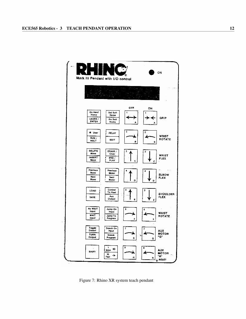
4.3 A to H start motor commands
starts motors A to H and moves them a number of encoder steps
The start command is used m instruct the controller to start a given motor and to move it in a given di-rection by a given number of encoder steps. The value is added to the move in progress.
The format of the command is
< motorlD > [< sign >] < encodercounts >< return >
where < motor ID > is an uppercase letter A-H, <sign> is an optional + or - character ( if no character ispresent a + is assumed ) and <encoder counts> is a number from 0 to 127.
Example : for programming in BASIC: PRINT “C-93”
The above command will move the “C” motor in the negative direction by an additional 93 encoderpositions. The positive sign is not needed for moves in the positive direction and may be omitted. Thecarriage return is used to execute the command. Only one motor can be addressed at one time. Othersamples of the command are:
B-6 <return>A+21 <return>C33 <return>D-125 <return>H <return> (clears the move count buffer, therefore no move is made)
<return> (repeats the previous move)
Sending only a carriage return without a motor move, after a motor move command, repeats the last motormove command. Even carriage returns that are part of another command (discussed later) will re-issue themove command. In order to cancel a move command that would be carried out by the receipt of a carriagereturn, all commands should be preceded by a motor ID character (A thru H). Any motor ID letter sets themove buffer to zero if there are no numbers attached to it. Once the move buffer is cleared other commandswith carriage returns will not activate the move instruction. For example the commands Similar to mefollowing will clear the move buffer.
A <return>CI <return>EJ <return>BL <return>
Once the move buffer is cleared, other commands may be issued without the motor ID characters. The movebuffer is active after each nor-zero motor move command. It should be cleared before using commandswhen necessary.
4.4 I I-Inquiry command
Returns status of microswitches on motor ports C,D,E,F,G,and H
POSTECH ECE Control Lab., Eng. Bldg. 2-408
ECE565 Robotics - 4 CONTROL AND PROGRAMMING 17
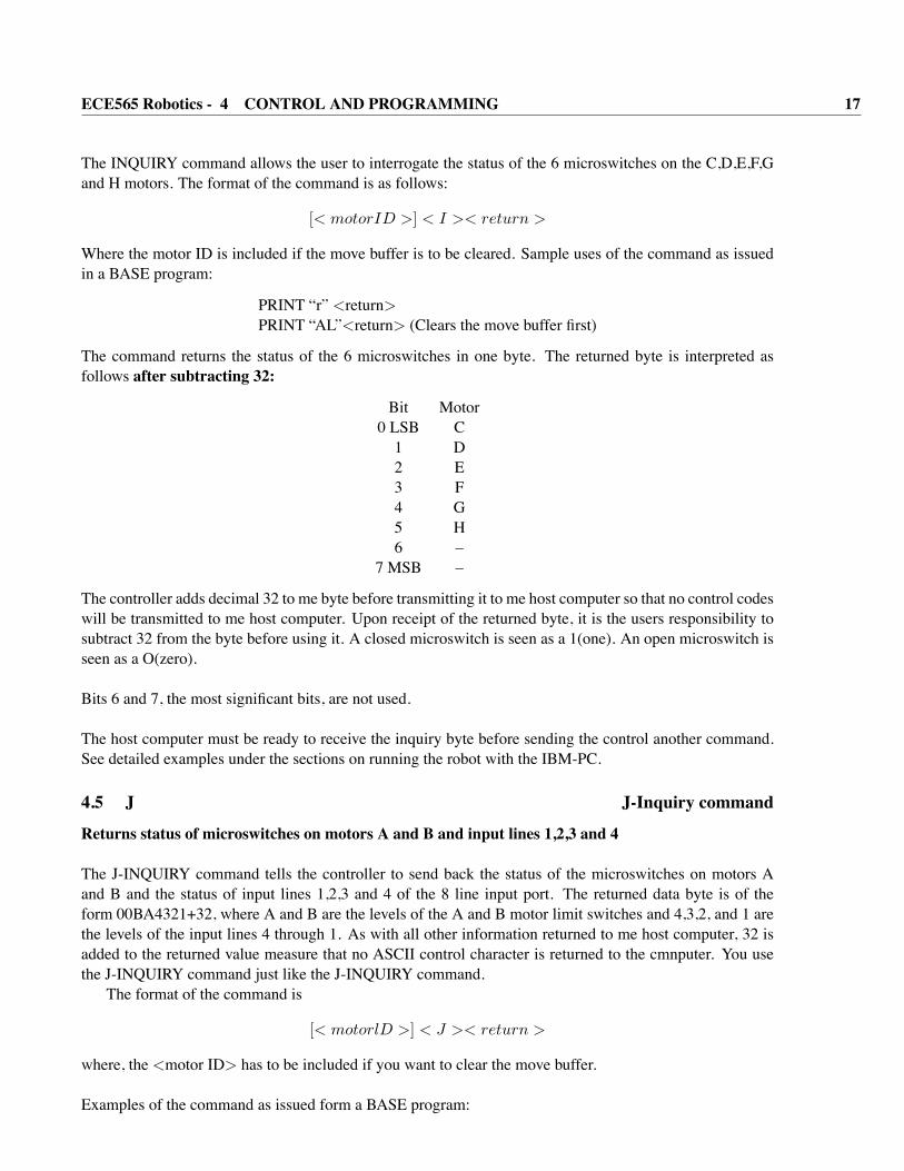
The INQUIRY command allows the user to interrogate the status of the 6 microswitches on the C,D,E,F,Gand H motors. The format of the command is as follows:
[< motorID >] < I >< return >
Where the motor ID is included if the move buffer is to be cleared. Sample uses of the command as issuedin a BASE program:
PRINT “r” <return>PRINT “AL”<return> (Clears the move buffer first)
The command returns the status of the 6 microswitches in one byte. The returned byte is interpreted asfollows after subtracting 32:
Bit Motor0 LSB C1 D2 E3 F4 G5 H6 –
7 MSB –
The controller adds decimal 32 to me byte before transmitting it to me host computer so that no control codeswill be transmitted to me host computer. Upon receipt of the returned byte, it is the users responsibility tosubtract 32 from the byte before using it. A closed microswitch is seen as a 1(one). An open microswitch isseen as a O(zero).
Bits 6 and 7, the most significant bits, are not used.
The host computer must be ready to receive the inquiry byte before sending the control another command.See detailed examples under the sections on running the robot with the IBM-PC.
4.5 J J-Inquiry command
Returns status of microswitches on motors A and B and input lines 1,2,3 and 4
The J-INQUIRY command tells the controller to send back the status of the microswitches on motors Aand B and the status of input lines 1,2,3 and 4 of the 8 line input port. The returned data byte is of theform 00BA4321+32, where A and B are the levels of the A and B motor limit switches and 4,3,2, and 1 arethe levels of the input lines 4 through 1. As with all other information returned to me host computer, 32 isadded to the returned value measure that no ASCII control character is returned to the cmnputer. You usethe J-INQUIRY command just like the J-INQUIRY command.
The format of the command is
[< motorlD >] < J >< return >
where, the <motor ID> has to be included if you want to clear the move buffer.
Examples of the command as issued form a BASE program:
POSTECH ECE Control Lab., Eng. Bldg. 2-408

ECE565 Robotics - 4 CONTROL AND PROGRAMMING 18
PRINT“J” <return>PRINT“CJ” <return> (Clears the move buffer first)
When interpreting the bits returned by the motor controller, a value of 0 means that the input is low ( or thata microswitch is closed). A value of 1 means that the input is high (or that a microswitch is open).
Bit Meaning0 LSB Input 11 Input 22 Input 33 Input 44 Motor “A” Limit Switch5 Motor “B” Limit Switch6 –
7 MSB –
Bits 6 and 7 are not used.
The controller adds decimal 32 to me byte before transmitting it to me host computer so that no ASCIIcontrol codes will be transmitted to me host computer.
The host computer must be ready to receive the inquiry byte before sending the controller another com-mand. See detailed examples under the sections on running the robot with the IBM-PC.
4.6 K K-INQUIRY command
Returns the status of input lines 5,6,7 and 8.
The K-INQUIRY command tells the controller to send back the status of inputs 5 through 8 of the 8 lineinput port. The returned data is of the form 00008765+32, where 8,7,6 and 5 are the levels of input lines 8through 5. The format and usage of the K command is similar to me I and J commands.
The format of the command is
[< motorlD >] < K >< return > .
where, the ¡motor ID¿ has to be included if you want to clear the move buffer. Examples of command asissued form a BASIC program:
PRINT “K” <return>PRINT “EK” <return> (Clears the move buffer first)
The command returns values that may be interpreted as follows after subtracting 32 from the byte received.
Bit Meaning0 LSB Input 51 Input 62 Input 73 Input 84 –5 –6 –
7 MSB –
POSTECH ECE Control Lab., Eng. Bldg. 2-408
ECE565 Robotics - 4 CONTROL AND PROGRAMMING 19
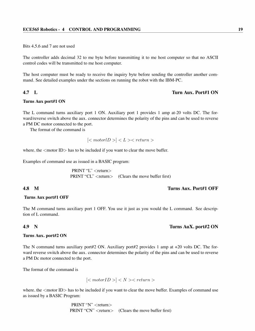
Bits 4,5,6 and 7 are not used
The controller adds decimal 32 to me byte before transmitting it to me host computer so that no ASCIIcontrol codes will be transmitted to me host computer.
The host computer must be ready to receive the inquiry byte before sending the controller another com-mand. See detailed examples under the sections on running the robot with the IBM-PC.
4.7 L Turn Aux. Port#1 ON
Turns Aux port#1 ON
The L command turns auxiliary port 1 ON. Auxiliary port 1 provides 1 amp at-20 volts DC. The for-ward/reverse switch above the aux. connector determines the polarity of the pins and can be used to reversea PM DC motor connected to the port.
The format of the command is
[< motorlD >] < L >< return >
where, the <motor ID> has to be included if you want to clear the move buffer.
Examples of command use as issued in a BASIC program:
PRINT “L” <return>PRINT “CL” <return> (Clears the move buffer first)
4.8 M Turns Aux. Port#1 OFF
Turns Aux port#1 OFF
The M command turns auxiliary port 1 OFF. You use it just as you would the L command. See descrip-tion of L command.
4.9 N Turns AuX. port#2 ON
Turns Aux. port#2 ON
The N command turns auxiliary port#2 ON. Auxiliary port#2 provides 1 amp at +20 volts DC. The for-ward reverse switch above the aux. connector determines the polarity of the pins and can be used to reversea PM Dc motor connected to the port.
The format of the command is
[< motorID >] < N >< return >
where, the <motor ID> has to be included if you want to clear the move buffer. Examples of command useas issued by a BASIC Program:
PRINT “N” <return>PRINT “CN” <return> (Clears the move buffer first)
POSTECH ECE Control Lab., Eng. Bldg. 2-408

ECE565 Robotics - 4 CONTROL AND PROGRAMMING 20
4.10 O Turns Aux. Port#2 OFF
Turns Aux Port#2 OFF
The command turns auxiliary port 2 OFF. You use it just as you would the N command see descriptionof N command.
4.11 P set output Line High
Sets an output line HlGH
The P command tells the controller that the next digit it receives identifies the output line to be set high.The 8 output lines of the output port are numbered from 1 to 8. The output lines are set high during startupand after a reset. The Rhino controller output lines provide TTL level signals.
The format of the command is
[< motorID >] < P >< outputlinenumber >< return >
where the <motor ID> has to be included if you want to clear the move buffer. Examples of command useas issued by a BASIC program:
PRINT “P3” <return>PRINT “AP6” <return> (Clears the move buffer first)
4.12 Q Reset
Resets the entire Controller
The Q command tells the controller to reset itself. The controller will clear all of its internal registers,turn off all motors, turn off all the auxiliary ports, set all output lines high and reset its communication portaccording to the BAUD switch in the controller.
The Q command is a convenient way of resetting the controller (in software) without having to press thereset button.
The format of the command is< Q >< return >
Examples of command use as issued in a BASIC program:
PRINT “Q” <return>
complicated software programs often start with the “Q” command ensure that the controller is at a known(reset) state when the program starts.
4.13 R set output Line Low
sets an output line LOW
The R command is similar to me P command but the next digit received after the R identifies the output
POSTECH ECE Control Lab., Eng. Bldg. 2-408
ECE565 Robotics - 5 SIMULATOR : SIMULATR 21
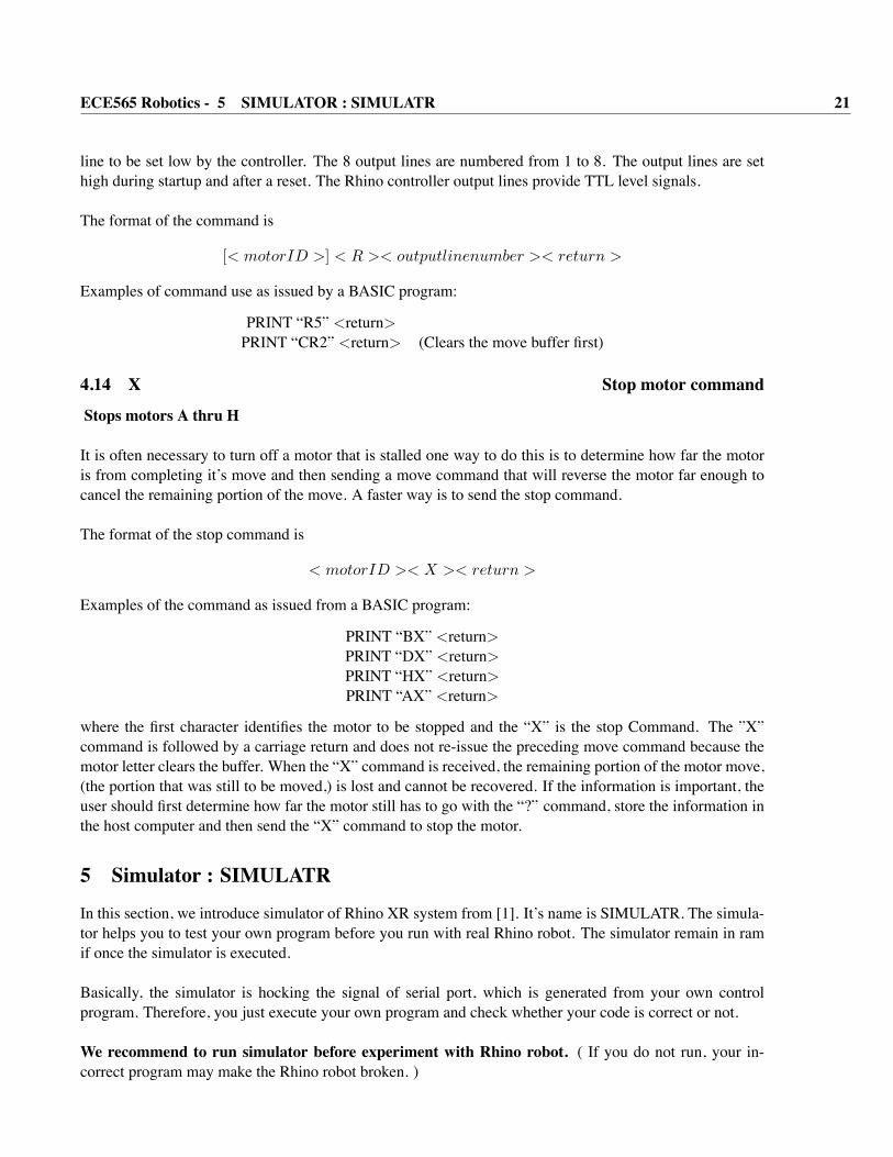
line to be set low by the controller. The 8 output lines are numbered from 1 to 8. The output lines are sethigh during startup and after a reset. The Rhino controller output lines provide TTL level signals.
The format of the command is
[< motorID >] < R >< outputlinenumber >< return >
Examples of command use as issued by a BASIC program:
PRINT “R5” <return>PRINT “CR2” <return> (Clears the move buffer first)
4.14 X Stop motor command
Stops motors A thru H
It is often necessary to turn off a motor that is stalled one way to do this is to determine how far the motoris from completing it’s move and then sending a move command that will reverse the motor far enough tocancel the remaining portion of the move. A faster way is to send the stop command.
The format of the stop command is
< motorID >< X >< return >
Examples of the command as issued from a BASIC program:
PRINT “BX” <return>PRINT “DX” <return>PRINT “HX” <return>PRINT “AX” <return>
where the first character identifies the motor to be stopped and the “X” is the stop Command. The ”X”command is followed by a carriage return and does not re-issue the preceding move command because themotor letter clears the buffer. When the “X” command is received, the remaining portion of the motor move,(the portion that was still to be moved,) is lost and cannot be recovered. If the information is important, theuser should first determine how far the motor still has to go with the “?” command, store the information inthe host computer and then send the “X” command to stop the motor.
5 Simulator : SIMULATRIn this section, we introduce simulator of Rhino XR system from [1]. It’s name is SIMULATR. The simula-tor helps you to test your own program before you run with real Rhino robot. The simulator remain in ramif once the simulator is executed.
Basically, the simulator is hocking the signal of serial port, which is generated from your own controlprogram. Therefore, you just execute your own program and check whether your code is correct or not.
We recommend to run simulator before experiment with Rhino robot. ( If you do not run, your in-correct program may make the Rhino robot broken. )
POSTECH ECE Control Lab., Eng. Bldg. 2-408

ECE565 Robotics - REFERENCES 22
You can get the simulator from Homepage of this class or TA ( You can email to me).
We attach a few pages of usage of the simulator. From these, you can get all information about the simulator,SIMULATR.
Note. 1 Owner’s manual, Service manual and Student’s manual of Rhino XR system are available. Ifyou want those, you can copy it. Come to Control Lab. at laboratory.Note. 2 Please let me know errors in this material for other people.
References[1] Rhino Robots, Inc., Owner’s Manual.
[2] Rhino Robots, Inc., Rhino XR-3 Robot Instructor’s Manual.
[3] Rhino Robots, Inc., Rhino XR-3 Robot Service Manual.
[4] Rhino Robots, Inc., Rhino XR-3 Robot Software Manual.
POSTECH ECE Control Lab., Eng. Bldg. 2-408

ECE565 Robotics - REFERENCES 23
POSTECH ECE Control Lab., Eng. Bldg. 2-408

ECE565 Robotics - REFERENCES 24
POSTECH ECE Control Lab., Eng. Bldg. 2-408
ECE565 Robotics - REFERENCES 25
POSTECH ECE Control Lab., Eng. Bldg. 2-408
ECE565 Robotics - REFERENCES 26
POSTECH ECE Control Lab., Eng. Bldg. 2-408

ECE565 Robotics - REFERENCES 27
POSTECH ECE Control Lab., Eng. Bldg. 2-408

ECE565 Robotics - REFERENCES 28
POSTECH ECE Control Lab., Eng. Bldg. 2-408
ECE565 Robotics - REFERENCES 29
POSTECH ECE Control Lab., Eng. Bldg. 2-408

ECE565 Robotics - REFERENCES 30
POSTECH ECE Control Lab., Eng. Bldg. 2-408