the safety integrity level (sil) selection, allocation and ... · which defines different methods...
TRANSCRIPT
The Safety Integrity Level (SIL) selection, allocation and Verification: The ETCS case study Abstract: This paper aims to demonstrate the application Safety Integrity Level (SIL) for
railway industry application as part of RAMS program implementation based on the standard
EN 50129 concept. Such risk analysis enables to define a semi-quantitative safety requirement
for each safety function as well as to allocate the SIL target for hardware and software
associated functions. Moreover, such SIL target needs to be demonstrated as part of SIL
verification, which is a quantitative assessment based on fault tree analysis and field historical
data. In order to demonstrate the SIL concept application a cases study concerns ETCS on
board will be demonstrated
Key Words: FHA, SIL, Risk Matrix, THL, ETCS
Author: Dr. Eduardo Calixto, ECC, Germany
(This paper is fully described in the book “RAMS and LCC engineering: Analysis, Modelling and Optimization (Chapter 9). Author: Dr. Eduardo Calixto – www.amazon.com)
1 - Safety Integrity Level Analysis (SIL)
The safety integrity level aims to define the level of integrity for a specific safety function,
which depends on the criticality concerning safety related function. Different from IEC 61508,
which defines different methods to SIL assignment methods such as risk matrix, graph methods
and individual risk. However, the EN 50129 defines, for the railways, electric and electronic
safety critical equipment, a simple SIL assignment method, which is based on the tolerable
hazard rate classification defined in the Functional hazard analysis. Therefore, based on the
risk assessment result defined in the Functional Hazard Analysis, the Tolerable Hazard Rate
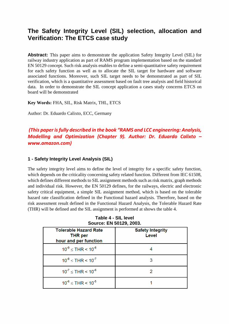
(THR) will be defined and the SIL assignment is performed at shows the table 4.
Table 4 - SIL level Source: EN 50129, 2003.
For each THR there will be a SIL level, which varies from 1 to 4. The highest value of THR,
the highest SIL level assigned to the safety function. Therefore, it´s important to associate the
frequency of hazard occurrence after mitigation with the THR and the SIL level as described
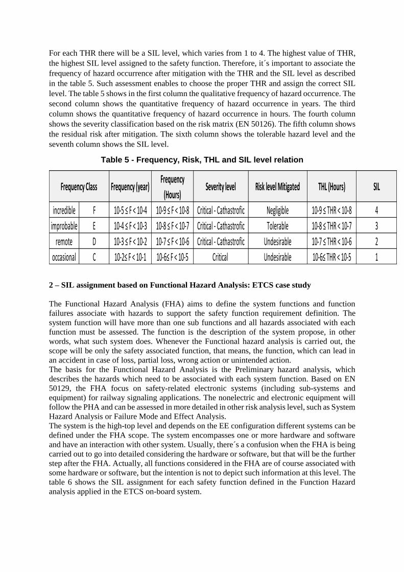
in the table 5. Such assessment enables to choose the proper THR and assign the correct SIL
level. The table 5 shows in the first column the qualitative frequency of hazard occurrence. The
second column shows the quantitative frequency of hazard occurrence in years. The third
column shows the quantitative frequency of hazard occurrence in hours. The fourth column
shows the severity classification based on the risk matrix (EN 50126). The fifth column shows
the residual risk after mitigation. The sixth column shows the tolerable hazard level and the
seventh column shows the SIL level.
Table 5 - Frequency, Risk, THL and SIL level relation
2 – SIL assignment based on Functional Hazard Analysis: ETCS case study
The Functional Hazard Analysis (FHA) aims to define the system functions and function
failures associate with hazards to support the safety function requirement definition. The
system function will have more than one sub functions and all hazards associated with each
function must be assessed. The function is the description of the system propose, in other
words, what such system does. Whenever the Functional hazard analysis is carried out, the
scope will be only the safety associated function, that means, the function, which can lead in
an accident in case of loss, partial loss, wrong action or unintended action.
The basis for the Functional Hazard Analysis is the Preliminary hazard analysis, which
describes the hazards which need to be associated with each system function. Based on EN
50129, the FHA focus on safety-related electronic systems (including sub-systems and
equipment) for railway signaling applications. The nonelectric and electronic equipment will
follow the PHA and can be assessed in more detailed in other risk analysis level, such as System
Hazard Analysis or Failure Mode and Effect Analysis.
The system is the high-top level and depends on the EE configuration different systems can be
defined under the FHA scope. The system encompasses one or more hardware and software
and have an interaction with other system. Usually, there´s a confusion when the FHA is being
carried out to go into detailed considering the hardware or software, but that will be the further
step after the FHA. Actually, all functions considered in the FHA are of course associated with
some hardware or software, but the intention is not to depict such information at this level. The
table 6 shows the SIL assignment for each safety function defined in the Function Hazard
analysis applied in the ETCS on-board system.
Frequency (year)Frequency
(Hours)Severity level Risk level Mitigated THL (Hours) SIL
incredible F 10-5 ≤ F < 10-4 10-9 ≤ F < 10-8 Critical - Cathastrofic Negligible 10-9 ≤ THR < 10-8 4
improbable E 10-4 ≤ F < 10-3 10-8 ≤ F < 10-7 Critical - Cathastrofic Tolerable 10-8 ≤ THR < 10-7 3
remote D 10-3 ≤ F < 10-2 10-7 ≤ F < 10-6 Critical - Cathastrofic Undesirable 10-7 ≤ THR < 10-6 2
occasional C 10-2≤ F < 10-1 10-6≤ F < 10-5 Critical Undesirable 10-6≤ THR < 10-5 1
Frequency Class
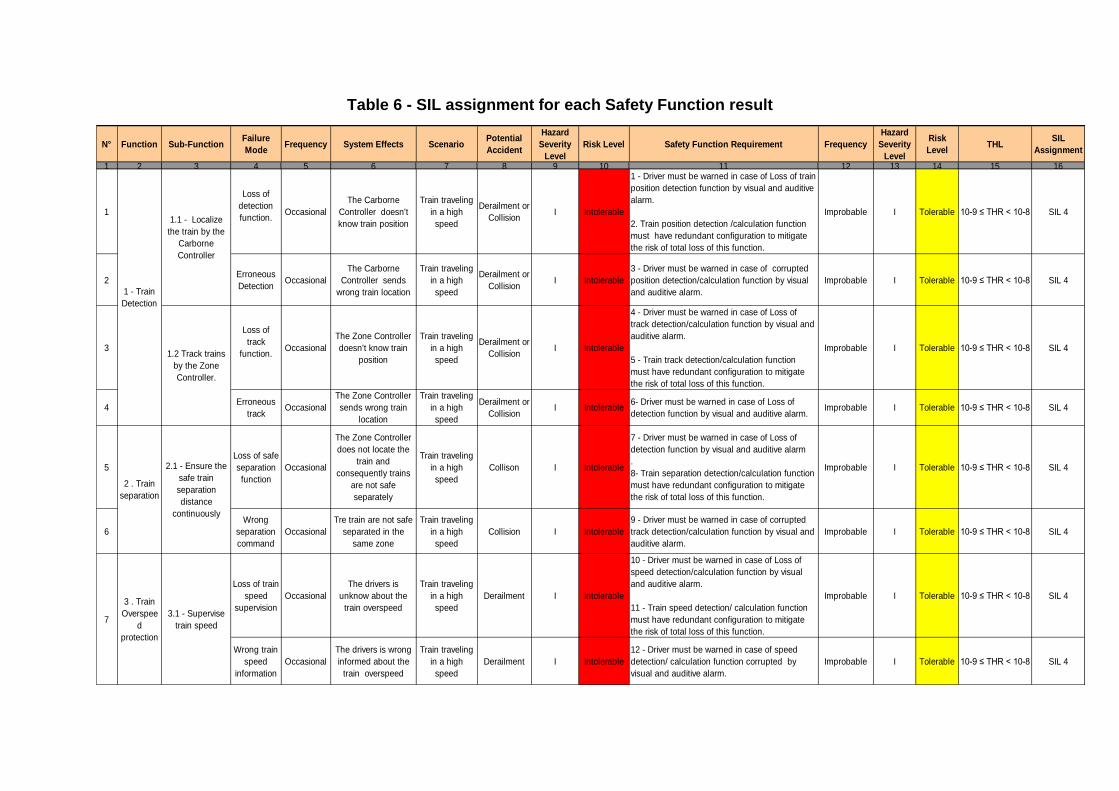
Table 6 - SIL assignment for each Safety Function result
N° Function Sub-FunctionFailure
ModeFrequency System Effects Scenario
Potential
Accident
Hazard
Severity
Level
Risk Level Safety Function Requirement Frequency
Hazard
Severity
Level
Risk
LevelTHL
SIL
Assignment
1 2 3 4 5 6 7 8 9 10 11 12 13 14 15 16
1
Loss of
detection
function.Occasional
The Carborne
Controller doesn't
know train position
Train traveling
in a high
speed
Derailment or
CollisionI Intolerable
1 - Driver must be warned in case of Loss of train
position detection function by visual and auditive
alarm.
2. Train position detection /calculation function
must have redundant configuration to mitigate
the risk of total loss of this function.
Improbable I Tolerable 10-9 ≤ THR < 10-8 SIL 4
2Erroneous
Detection Occasional
The Carborne
Controller sends
wrong train location
Train traveling
in a high
speed
Derailment or
CollisionI Intolerable
3 - Driver must be warned in case of corrupted
position detection/calculation function by visual
and auditive alarm.
Improbable I Tolerable 10-9 ≤ THR < 10-8 SIL 4
3
Loss of
track
function.Occasional
The Zone Controller
doesn't know train
position
Train traveling
in a high
speed
Derailment or
CollisionI Intolerable
4 - Driver must be warned in case of Loss of
track detection/calculation function by visual and
auditive alarm.
5 - Train track detection/calculation function
must have redundant configuration to mitigate
the risk of total loss of this function.
Improbable I Tolerable 10-9 ≤ THR < 10-8 SIL 4
4Erroneous
trackOccasional
The Zone Controller
sends wrong train
location
Train traveling
in a high
speed
Derailment or
CollisionI Intolerable
6- Driver must be warned in case of Loss of
detection function by visual and auditive alarm.Improbable I Tolerable 10-9 ≤ THR < 10-8 SIL 4
5
Loss of safe
separation
function
Occasional
The Zone Controller
does not locate the
train and
consequently trains
are not safe
separately
Train traveling
in a high
speed
Collison I Intolerable
7 - Driver must be warned in case of Loss of
detection function by visual and auditive alarm
.
8- Train separation detection/calculation function
must have redundant configuration to mitigate
the risk of total loss of this function.
Improbable I Tolerable 10-9 ≤ THR < 10-8 SIL 4
6
Wrong
separation
command
Occasional
Tre train are not safe
separated in the
same zone
Train traveling
in a high
speed
Collision I Intolerable
9 - Driver must be warned in case of corrupted
track detection/calculation function by visual and
auditive alarm.
Improbable I Tolerable 10-9 ≤ THR < 10-8 SIL 4
Loss of train
speed
supervision
Occasional
The drivers is
unknow about the
train overspeed
Train traveling
in a high
speed
Derailment I Intolerable
10 - Driver must be warned in case of Loss of
speed detection/calculation function by visual
and auditive alarm.
11 - Train speed detection/ calculation function
must have redundant configuration to mitigate
the risk of total loss of this function.
Improbable I Tolerable 10-9 ≤ THR < 10-8 SIL 4
Wrong train
speed
information
Occasional
The drivers is wrong
informed about the
train overspeed
Train traveling
in a high
speed
Derailment I Intolerable
12 - Driver must be warned in case of speed
detection/ calculation function corrupted by
visual and auditive alarm.
Improbable I Tolerable 10-9 ≤ THR < 10-8 SIL 4
7
3 . Train
Overspee
d
protection
3.1 - Supervise
train speed
1 - Train
Detection
1.1 - Localize
the train by the
Carborne
Controller
1.2 Track trains
by the Zone
Controller.
2 . Train
separation
2.1 - Ensure the
safe train
separation
distance
continuously
2 – SIL allocation based on Technical Safety Architecture
After the SIL assignment for each safety function (and sub-function), it´s necessary to allocate
the SIL assign targets to each equipment related function (hardware and software). Therefore,
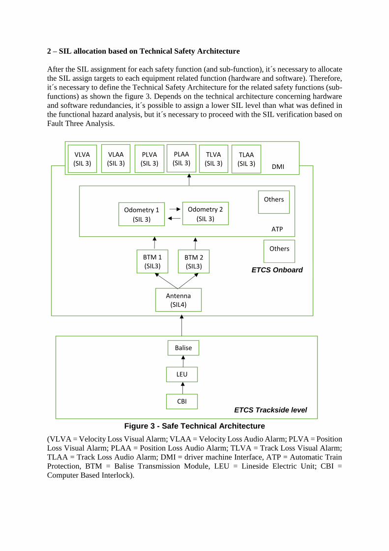
it´s necessary to define the Technical Safety Architecture for the related safety functions (sub-
functions) as shown the figure 3. Depends on the technical architecture concerning hardware
and software redundancies, it´s possible to assign a lower SIL level than what was defined in
the functional hazard analysis, but it´s necessary to proceed with the SIL verification based on
Fault Three Analysis.
Figure 3 - Safe Technical Architecture
(VLVA = Velocity Loss Visual Alarm; VLAA = Velocity Loss Audio Alarm; PLVA = Position
Loss Visual Alarm; PLAA = Position Loss Audio Alarm; TLVA = Track Loss Visual Alarm;
TLAA = Track Loss Audio Alarm; DMI = driver machine Interface, ATP = Automatic Train
Protection, BTM = Balise Transmission Module, LEU = Lineside Electric Unit; CBI =
Computer Based Interlock).
BTM 1 (SIL3)
BTM 2 (SIL3)
Others
Odometry 1
(SIL 3)
Others
ETCS Onboard
ATP
Odometry 2
(SIL 3)
DMI
VLVA (SIL 3)
VLAA (SIL 3)
PLVA (SIL 3)
PLAA (SIL 3)
TLVA (SIL 3)
TLAA (SIL 3)
ETCS Trackside level
1
Balise
LEU
CBI
Antenna (SIL4)
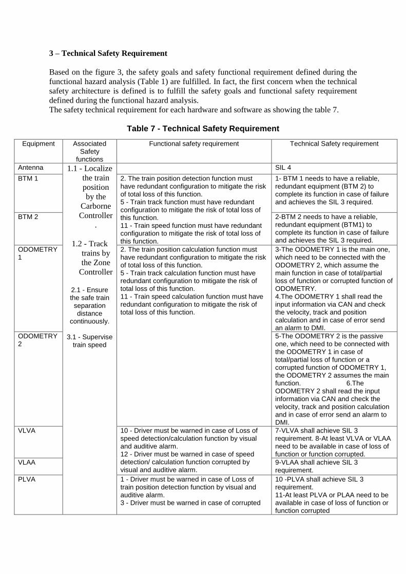
3 – Technical Safety Requirement
Based on the figure 3, the safety goals and safety functional requirement defined during the
functional hazard analysis (Table 1) are fulfilled. In fact, the first concern when the technical
safety architecture is defined is to fulfill the safety goals and functional safety requirement
defined during the functional hazard analysis.
The safety technical requirement for each hardware and software as showing the table 7.
Table 7 - Technical Safety Requirement
Equipment Associated Safety
functions
Functional safety requirement Technical Safety requirement
Antenna 1.1 - Localize
the train
position
by the
Carborne
Controller
.
1.2 - Track
trains by
the Zone
Controller
2.1 - Ensure the safe train
separation distance
continuously.
3.1 - Supervise train speed
SIL 4
BTM 1 2. The train position detection function must have redundant configuration to mitigate the risk of total loss of this function. 5 - Train track function must have redundant configuration to mitigate the risk of total loss of this function. 11 - Train speed function must have redundant configuration to mitigate the risk of total loss of this function.
1- BTM 1 needs to have a reliable, redundant equipment (BTM 2) to complete its function in case of failure and achieves the SIL 3 required.
BTM 2 2-BTM 2 needs to have a reliable, redundant equipment (BTM1) to complete its function in case of failure and achieves the SIL 3 required.
ODOMETRY 1
2. The train position calculation function must have redundant configuration to mitigate the risk of total loss of this function. 5 - Train track calculation function must have redundant configuration to mitigate the risk of total loss of this function. 11 - Train speed calculation function must have redundant configuration to mitigate the risk of total loss of this function.
3-The ODOMETRY 1 is the main one, which need to be connected with the ODOMETRY 2, which assume the main function in case of total/partial loss of function or corrupted function of ODOMETRY. 4.The ODOMETRY 1 shall read the input information via CAN and check the velocity, track and position calculation and in case of error send an alarm to DMI.
ODOMETRY 2
5-The ODOMETRY 2 is the passive one, which need to be connected with the ODOMETRY 1 in case of total/partial loss of function or a corrupted function of ODOMETRY 1, the ODOMETRY 2 assumes the main function. 6.The ODOMETRY 2 shall read the input information via CAN and check the velocity, track and position calculation and in case of error send an alarm to DMI.
VLVA 10 - Driver must be warned in case of Loss of speed detection/calculation function by visual and auditive alarm. 12 - Driver must be warned in case of speed detection/ calculation function corrupted by visual and auditive alarm.
7-VLVA shall achieve SIL 3 requirement. 8-At least VLVA or VLAA need to be available in case of loss of function or function corrupted.
VLAA 9-VLAA shall achieve SIL 3 requirement.
PLVA 1 - Driver must be warned in case of Loss of train position detection function by visual and auditive alarm. 3 - Driver must be warned in case of corrupted
10 -PLVA shall achieve SIL 3 requirement. 11-At least PLVA or PLAA need to be available in case of loss of function or function corrupted
PLAA position detection/calculation function of visual and auditive alarm.
12-PLAA shall achieve SIL 3 requirement.
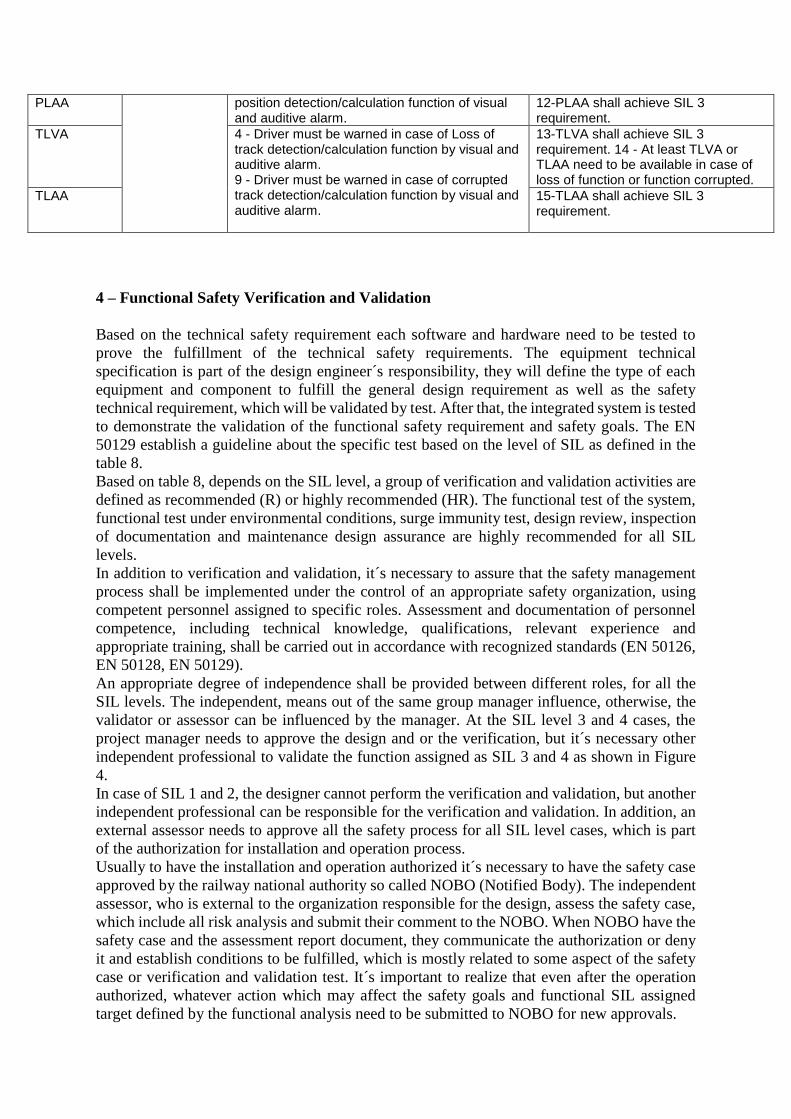
TLVA 4 - Driver must be warned in case of Loss of track detection/calculation function by visual and auditive alarm. 9 - Driver must be warned in case of corrupted track detection/calculation function by visual and auditive alarm.
13-TLVA shall achieve SIL 3 requirement. 14 - At least TLVA or TLAA need to be available in case of loss of function or function corrupted.
TLAA 15-TLAA shall achieve SIL 3 requirement.
4 – Functional Safety Verification and Validation
Based on the technical safety requirement each software and hardware need to be tested to
prove the fulfillment of the technical safety requirements. The equipment technical
specification is part of the design engineer´s responsibility, they will define the type of each
equipment and component to fulfill the general design requirement as well as the safety
technical requirement, which will be validated by test. After that, the integrated system is tested
to demonstrate the validation of the functional safety requirement and safety goals. The EN
50129 establish a guideline about the specific test based on the level of SIL as defined in the
table 8.
Based on table 8, depends on the SIL level, a group of verification and validation activities are
defined as recommended (R) or highly recommended (HR). The functional test of the system,
functional test under environmental conditions, surge immunity test, design review, inspection
of documentation and maintenance design assurance are highly recommended for all SIL
levels.
In addition to verification and validation, it´s necessary to assure that the safety management
process shall be implemented under the control of an appropriate safety organization, using
competent personnel assigned to specific roles. Assessment and documentation of personnel
competence, including technical knowledge, qualifications, relevant experience and
appropriate training, shall be carried out in accordance with recognized standards (EN 50126,
EN 50128, EN 50129).
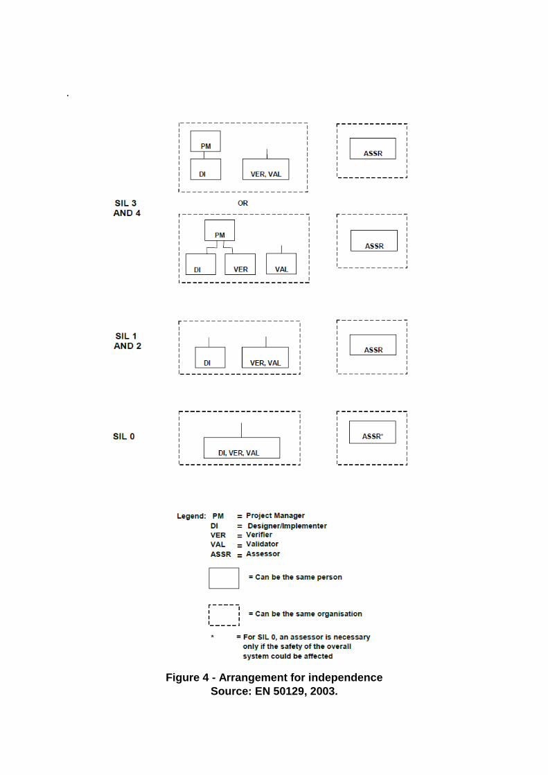
An appropriate degree of independence shall be provided between different roles, for all the
SIL levels. The independent, means out of the same group manager influence, otherwise, the
validator or assessor can be influenced by the manager. At the SIL level 3 and 4 cases, the
project manager needs to approve the design and or the verification, but it´s necessary other
independent professional to validate the function assigned as SIL 3 and 4 as shown in Figure
4.
In case of SIL 1 and 2, the designer cannot perform the verification and validation, but another
independent professional can be responsible for the verification and validation. In addition, an
external assessor needs to approve all the safety process for all SIL level cases, which is part
of the authorization for installation and operation process.
Usually to have the installation and operation authorized it´s necessary to have the safety case
approved by the railway national authority so called NOBO (Notified Body). The independent
assessor, who is external to the organization responsible for the design, assess the safety case,
which include all risk analysis and submit their comment to the NOBO. When NOBO have the
safety case and the assessment report document, they communicate the authorization or deny
it and establish conditions to be fulfilled, which is mostly related to some aspect of the safety
case or verification and validation test. It´s important to realize that even after the operation
authorized, whatever action which may affect the safety goals and functional SIL assigned
target defined by the functional analysis need to be submitted to NOBO for new approvals.
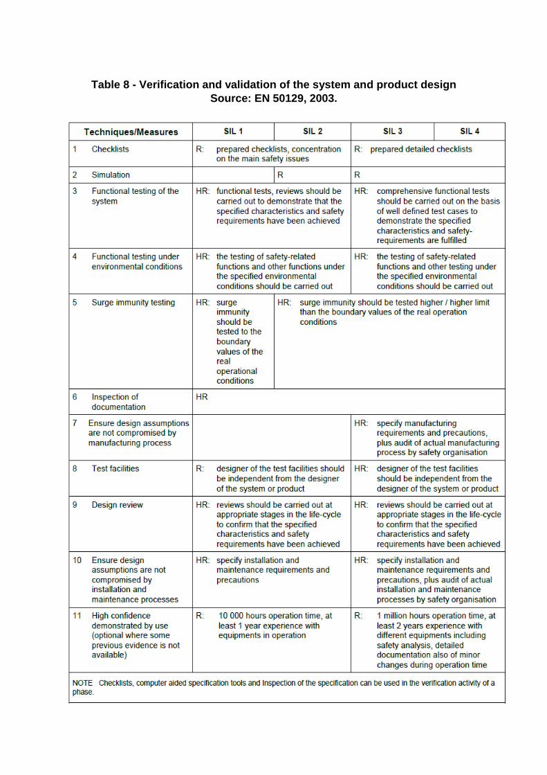
Table 8 - Verification and validation of the system and product design
Source: EN 50129, 2003.
.
Figure 4 - Arrangement for independence
Source: EN 50129, 2003.
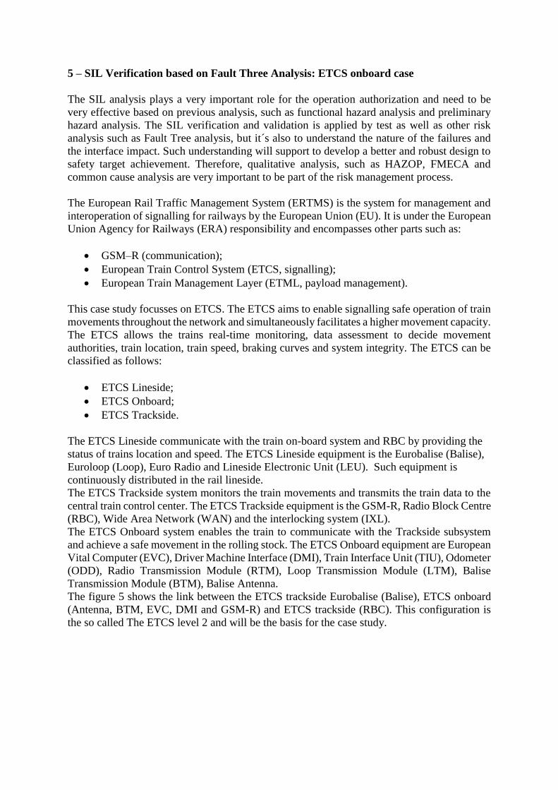
5 – SIL Verification based on Fault Three Analysis: ETCS onboard case
The SIL analysis plays a very important role for the operation authorization and need to be
very effective based on previous analysis, such as functional hazard analysis and preliminary
hazard analysis. The SIL verification and validation is applied by test as well as other risk
analysis such as Fault Tree analysis, but it´s also to understand the nature of the failures and
the interface impact. Such understanding will support to develop a better and robust design to
safety target achievement. Therefore, qualitative analysis, such as HAZOP, FMECA and
common cause analysis are very important to be part of the risk management process.
The European Rail Traffic Management System (ERTMS) is the system for management and
interoperation of signalling for railways by the European Union (EU). It is under the European
Union Agency for Railways (ERA) responsibility and encompasses other parts such as:
• GSM–R (communication);
• European Train Control System (ETCS, signalling);
• European Train Management Layer (ETML, payload management).
This case study focusses on ETCS. The ETCS aims to enable signalling safe operation of train
movements throughout the network and simultaneously facilitates a higher movement capacity.
The ETCS allows the trains real-time monitoring, data assessment to decide movement
authorities, train location, train speed, braking curves and system integrity. The ETCS can be
classified as follows:
• ETCS Lineside;
• ETCS Onboard;
• ETCS Trackside.
The ETCS Lineside communicate with the train on-board system and RBC by providing the
status of trains location and speed. The ETCS Lineside equipment is the Eurobalise (Balise),
Euroloop (Loop), Euro Radio and Lineside Electronic Unit (LEU). Such equipment is
continuously distributed in the rail lineside.
The ETCS Trackside system monitors the train movements and transmits the train data to the
central train control center. The ETCS Trackside equipment is the GSM-R, Radio Block Centre
(RBC), Wide Area Network (WAN) and the interlocking system (IXL).
The ETCS Onboard system enables the train to communicate with the Trackside subsystem
and achieve a safe movement in the rolling stock. The ETCS Onboard equipment are European
Vital Computer (EVC), Driver Machine Interface (DMI), Train Interface Unit (TIU), Odometer
(ODD), Radio Transmission Module (RTM), Loop Transmission Module (LTM), Balise
Transmission Module (BTM), Balise Antenna.
The figure 5 shows the link between the ETCS trackside Eurobalise (Balise), ETCS onboard
(Antenna, BTM, EVC, DMI and GSM-R) and ETCS trackside (RBC). This configuration is
the so called The ETCS level 2 and will be the basis for the case study.
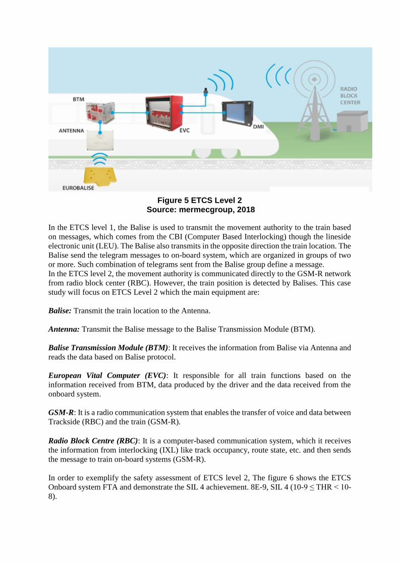
Figure 5 ETCS Level 2 Source: mermecgroup, 2018
In the ETCS level 1, the Balise is used to transmit the movement authority to the train based
on messages, which comes from the CBI (Computer Based Interlocking) though the lineside
electronic unit (LEU). The Balise also transmits in the opposite direction the train location. The
Balise send the telegram messages to on-board system, which are organized in groups of two
or more. Such combination of telegrams sent from the Balise group define a message.
In the ETCS level 2, the movement authority is communicated directly to the GSM-R network
from radio block center (RBC). However, the train position is detected by Balises. This case
study will focus on ETCS Level 2 which the main equipment are:
Balise: Transmit the train location to the Antenna.
Antenna: Transmit the Balise message to the Balise Transmission Module (BTM).
Balise Transmission Module (BTM): It receives the information from Balise via Antenna and
reads the data based on Balise protocol.
European Vital Computer (EVC): It responsible for all train functions based on the
information received from BTM, data produced by the driver and the data received from the
onboard system.
GSM-R: It is a radio communication system that enables the transfer of voice and data between
Trackside (RBC) and the train (GSM-R).
Radio Block Centre (RBC): It is a computer-based communication system, which it receives
the information from interlocking (IXL) like track occupancy, route state, etc. and then sends
the message to train on-board systems (GSM-R).
In order to exemplify the safety assessment of ETCS level 2, The figure 6 shows the ETCS
Onboard system FTA and demonstrate the SIL 4 achievement. 8E-9, SIL 4 (10-9 ≤ THR < 10-
8).
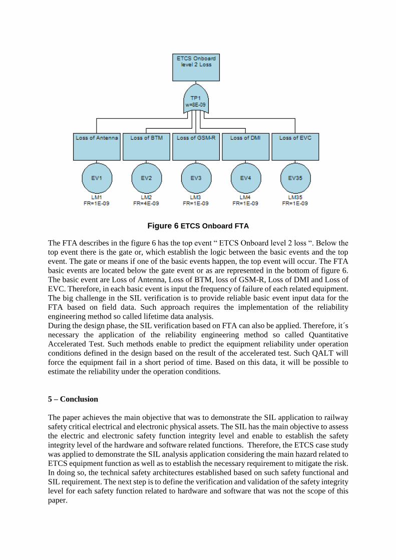
Figure 6 ETCS Onboard FTA
The FTA describes in the figure 6 has the top event “ ETCS Onboard level 2 loss “. Below the
top event there is the gate or, which establish the logic between the basic events and the top
event. The gate or means if one of the basic events happen, the top event will occur. The FTA
basic events are located below the gate event or as are represented in the bottom of figure 6.
The basic event are Loss of Antenna, Loss of BTM, loss of GSM-R, Loss of DMI and Loss of
EVC. Therefore, in each basic event is input the frequency of failure of each related equipment.
The big challenge in the SIL verification is to provide reliable basic event input data for the
FTA based on field data. Such approach requires the implementation of the reliability
engineering method so called lifetime data analysis.
During the design phase, the SIL verification based on FTA can also be applied. Therefore, it´s
necessary the application of the reliability engineering method so called Quantitative
Accelerated Test. Such methods enable to predict the equipment reliability under operation
conditions defined in the design based on the result of the accelerated test. Such QALT will
force the equipment fail in a short period of time. Based on this data, it will be possible to
estimate the reliability under the operation conditions.
5 – Conclusion
The paper achieves the main objective that was to demonstrate the SIL application to railway
safety critical electrical and electronic physical assets. The SIL has the main objective to assess
the electric and electronic safety function integrity level and enable to establish the safety
integrity level of the hardware and software related functions. Therefore, the ETCS case study
was applied to demonstrate the SIL analysis application considering the main hazard related to
ETCS equipment function as well as to establish the necessary requirement to mitigate the risk.
In doing so, the technical safety architectures established based on such safety functional and
SIL requirement. The next step is to define the verification and validation of the safety integrity
level for each safety function related to hardware and software that was not the scope of this
paper.
The SIL Analysis has as main advantages:
• To enable the SIL requirement;
• To define the technical safety architecture based on technical safety requirement;
• To define the hardware and software SIL allocation;
• To define the basis for the functional safety verification and validation test.
The FHA drawbacks are:
• Depends on specialist experience to define all SIL;
• Since being a qualitative analysis can be overestimate that will influence on more effort
than necessary to the SIL and functional safety requirement achievement;
• Since being a qualitative analysis can be underestimated that will influence on less
effort to the SIL and functional safety requirement achievement.
References
Calixto, Eduardo. Safety Science: Methods to Prevent Incident and worker Health Damage at
Workplace. ISBN-13: 978-1608059539 Bentham Science.
EN 50126, Railway applications – The specification and demonstration of reliability,
availability, maintainability and safety (RAMS). Part 1: Basic requirements and generic
process. Part 2: Guide to the application of EN 50126-1 for safety (CLC/TR). Part 3: Guide to
the application of EN 50126-1 for rolling stock RAM (CLC/TR), 1999.
EN 50128, Railway applications – Communication, signalling and processing systems –
Software for railway control and protection systems, 2001.
EN 50129, Railway applications – Communication, signaling and processing systems – Safety
related electronic systems for signaling, 2003.
ETCS level 2, http://www.mermecgroup.com/protect/atpatc-systems/630/ertmsetcs-level-
2.php
ISO 9001 Quality Management. ISO. International Organization for Standardization. Retrieved
2 October 2015.