the smart transformer: impact on the electric grid and
TRANSCRIPT

Chair of Power ElectronicsChristian-Albrechts-Universität zu KielKaiserstraße 224143 Kiel
The Smart Transformer: impact on the electric grid and
technology challengesMarco Liserre

Chair of Power Electronics | Marco Liserre| [email protected] slide 1
Outline
From the Solid-State-Transformer (SST) to the Smart Transformer
The Smart Transformer in the electric grid: identify the LV-grid, control the load/generation, offer services to MV-grid
The technological challenges of the DC/DC converter
The Smart Transformer: a grid-tailored Solid-State-Transformer

Chair of Power Electronics | Marco Liserre| [email protected] slide 2
From the Solid-State-Transformer (SST) to the Smart Transformer

Chair of Power Electronics | Marco Liserre| [email protected] slide 3
Concept and Definition of SST
Definition
• by Mr. McMurray, 1968 : Electronic Transformer is a device based on solid state switches which behaves in the same manner as a conventional power transformer.
• by Mr. Brooker, 1980 : Solid State Transformer is a apparatus for providing the voltage transformation functions of a conventional electrical power transformer with waveform conditioning capability.
• Currently: Power electronic based solution to replace the standard LF transformer, with the features:– galvanic isolation between the input and the output of the converter. – active control of power flow in both directions– compensation to disturbances in the power grid, such as variations of input voltage, short-term sag or
swell. – provide ports or interfaces to connect distributed power generators or energy storage device
• Smart Transformer: Solid State Transformer with control functionalities and communication.
Chair of Power Electronics | Marco Liserre| [email protected] slide 4
What is the „Smart“ Transformer ?
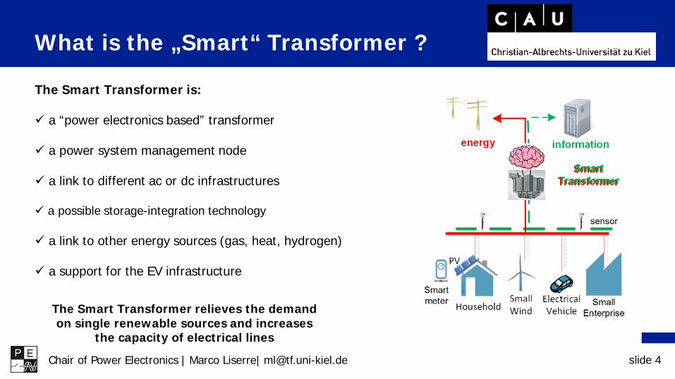
The Smart Transformer is:
a “power electronics based” transformer
a power system management node
a link to different ac or dc infrastructures
a possible storage-integration technology
a link to other energy sources (gas, heat, hydrogen)
a support for the EV infrastructure
The Smart Transformer relieves the demandon single renewable sources and increases
the capacity of electrical lines

Chair of Power Electronics | Marco Liserre| [email protected] slide 5
The Smart Transformer
A system level optimization !

Chair of Power Electronics | Marco Liserre| [email protected] slide 6
Smart Transformer services for the electric grid
• Voltage support (steady state and LVRT)
• Reactive power compensation at HV/MV substation
• Power quality improvements• Islanding control (high DG in LV)
• Integration of EV-charging stations • Integration of storage for dispatching• Reverse Power Flow limitation
Smart Transformer
• Impedance identification• Load identification• Reverse Power Flow limitation• ST overload control• Soft-load reduction• Damping of harmonics and resonances• LV-side power quality

Chair of Power Electronics | Marco Liserre| [email protected] slide 7
Control of the Smart Transformer
M. Liserre, G. Buticchi, M. Andresen, G. De Carne, L. F. Costa and Z. X. Zou, "The SmartTransformer: Impact on the Electric Grid and Technology Challenges," in IEEE IndustrialElectronics Magazine, vol. 10, no. 2, pp. 46-58, Summer 2016.

Chair of Power Electronics | Marco Liserre| [email protected] slide 8
The Smart Transformer in the electric grid: 1. identify the LV-grid, 2. control the load/generation, 3.
offer services to MV-grid
Chair of Power Electronics | Marco Liserre| [email protected] slide 9
The Smart Transformer in the electric grid: 1. identify the LV-grid, 2. control the load/generation, 3.
offer services to MV-grid

Chair of Power Electronics | Marco Liserre| [email protected] slide 10
On Line Load Identification
𝑃𝑃 = 𝑃𝑃0𝑉𝑉𝑉𝑉0
𝐾𝐾𝑝𝑝1 + 𝐾𝐾𝑓𝑓𝑓𝑓
𝑓𝑓 − 𝑓𝑓0𝑓𝑓0
𝑄𝑄 = 𝑄𝑄0𝑉𝑉𝑉𝑉0
𝐾𝐾𝑞𝑞1 + 𝐾𝐾𝑓𝑓𝑓𝑓
𝑓𝑓 − 𝑓𝑓0𝑓𝑓0
The load can be represented with an exponential model for the voltage and with a linear dependency from the frequency
V Independent of initial voltage and does not require initializationV Only one parameter is needed for active and one for reactive power.V The exponent is equal to load sensitivity to voltage
(1𝑎𝑎)
(1𝑏𝑏)
G. De Carne; M. Liserre; C. Vournas, "On-line load sensitivity identification in LV distribution grids," in IEEE Transactions on Power Systems , vol.PP, no.99, pp.1-1

Chair of Power Electronics | Marco Liserre| [email protected] slide 11
On Line Load Identification: Influence of DG on the identification
Integrating eq. (9) in eq. (4) we obtain:
𝐾𝐾𝑓𝑓 =⁄∆𝑃𝑃 𝑃𝑃0⁄∆𝑉𝑉 𝑉𝑉0
= 𝐾𝐾𝑓𝑓,𝐿𝐿𝑃𝑃𝐿𝐿
𝑃𝑃𝐿𝐿 − 𝑃𝑃𝐺𝐺(10)
The net load reacts in different way depending on the presence of DG.
Example:
𝐾𝐾𝑓𝑓 = 11
1 − 0= 1
𝑃𝑃𝐿𝐿 = 1,𝑃𝑃𝐺𝐺 = 0 → 𝑃𝑃0 = 1𝐾𝐾𝑓𝑓,𝐿𝐿 = 1
𝑃𝑃𝐿𝐿 = 1.5,𝑃𝑃𝐺𝐺 = 0.5 → 𝑃𝑃0 = 1𝐾𝐾𝑓𝑓,𝐿𝐿 = 1
𝐾𝐾𝑓𝑓 = 11.5
1.5 − 0.5= 1.5
𝑃𝑃 = 𝑃𝑃0𝑉𝑉𝑉𝑉0
1
𝑃𝑃 = 𝑃𝑃0𝑉𝑉𝑉𝑉0
1.5Linear
responseMore than linear
response

Chair of Power Electronics | Marco Liserre| [email protected] slide 12
Load parameter identification with respect to Voltage and Frequency
Load identification

Chair of Power Electronics | Marco Liserre| [email protected] slide 13
The Smart Transformer in the electric grid: 1. identify the LV-grid, 2. control the load/generation, 3.
offer services to MV-grid

Chair of Power Electronics | Marco Liserre| [email protected] slide 14
Soft Load Reduction
High load consumption can affect the system stability. The generators may not follow the load demand during grid contingencies.
In case of perturbations (e.g., faults) or critical conditions (e.g., devices overload), the load shedding represents an effective, although costly, solution.
The Smart Transformer can instead reduce the load consumption performing a “soft-load reduction”. Controlling the voltage amplitude in LV grid, the load power consumption can be shaped.
G. De Carne, G. Buticchi, M. Liserre, C. Vournas, “Load Control using SensitivityIdentification by means of Smart Transformer” IEEE Transactions on Smart Grid.

Chair of Power Electronics | Marco Liserre| [email protected] slide 15
Soft-load reduction
∆𝑃𝑃𝐴𝐴∗ =𝑃𝑃𝐴𝐴𝑉𝑉𝐴𝐴𝐾𝐾𝑓𝑓𝐴𝐴 𝑉𝑉 − 𝑉𝑉𝐴𝐴
𝑃𝑃𝐴𝐴∗ = 𝑃𝑃𝐴𝐴𝑉𝑉𝑉𝑉𝐴𝐴
𝐾𝐾𝑝𝑝𝑝𝑝
∆𝑃𝑃𝐴𝐴∗ + ∆𝑃𝑃𝐵𝐵∗ + ∆𝑃𝑃𝐶𝐶∗ = ∆𝑃𝑃
𝑉𝑉𝑉𝑉0
= 1 +∆𝑃𝑃+ 𝑃𝑃𝐴𝐴𝐾𝐾𝑓𝑓𝐴𝐴 + 𝑃𝑃𝐵𝐵𝐾𝐾𝑓𝑓𝐵𝐵 + 𝑃𝑃𝐶𝐶𝐾𝐾𝑓𝑓𝐶𝐶
𝑃𝑃𝐴𝐴𝑉𝑉𝐴𝐴𝐾𝐾𝑓𝑓𝐴𝐴 + 𝑃𝑃𝐵𝐵
𝑉𝑉𝐵𝐵𝐾𝐾𝑓𝑓𝐵𝐵 + 𝑃𝑃𝐶𝐶
𝑉𝑉𝐶𝐶𝐾𝐾𝑓𝑓𝐶𝐶
For each phase a,b,c
Differ.
The power variation in each phase gives:
Including (2) in (3) the general equation (4) is obtained
(1)
(2)
(3)
(4)

Chair of Power Electronics | Marco Liserre| [email protected] slide 16
Soft-load reduction
𝑉𝑉𝑉𝑉0
= 1 +∆𝑃𝑃
𝑃𝑃𝐴𝐴𝐾𝐾𝑓𝑓𝐴𝐴 + 𝑃𝑃𝐵𝐵𝐾𝐾𝑓𝑓𝐵𝐵 + 𝑃𝑃𝐶𝐶𝐾𝐾𝑓𝑓𝐶𝐶(5)
Simplifying (4) in (5), the voltage variation to impose in order to get the desired power variation ΔP is obtained:
Example in Figure: the reductionpower request is 5%. The load hasvoltage sensitivity coefficients varyingbetween 0.5 and 0.9 pu (plot above).
The Soft Reduction algorithm decidesto decrease the voltage of 0.08 pu(central plot).
The load shed during the consideredtime window is about 5% (plot below).

Chair of Power Electronics | Marco Liserre| [email protected] slide 17
The Smart Transformer in the electric grid: 1. identify the LV-grid, 2. control the load/generation, 3.
offer services to MV-grid

Chair of Power Electronics | Marco Liserre| [email protected] slide 18
Increasing DG hosting capacity
Typical DG penetration limits in MV feeders Voltage rise during light load Compensation of sudden loss of RES power
If at least some MV feeder loads are supplied through STs ST MV converter can apply voltage control Either locally or with remote measurement
ST can also provide emergency P control Acting on the LV connected load or DG
Gao, X., G. De Carne, M. Liserre, C. Vournas. "Increasing Integration of Wind Power in MediumVoltage Grid by voltage support of Smart Transformer." EWEA 2016.

Chair of Power Electronics | Marco Liserre| [email protected] slide 19
Feeder with Wind Gen
Typical Distribution feeder with Distributed Generation
Case studies for voltage regulation and DG hosting capacity

Chair of Power Electronics | Marco Liserre| [email protected] slide 20
MV feeder Test results
Without ST Consider
allowed overvoltage ΔV up to 2,5%
Max penetration limit 7.5 MW

Chair of Power Electronics | Marco Liserre| [email protected] slide 21
MV feeder Test results
With ST ΔV limit +2,5% Max penetration
limit 12 MW Increase of
4.5MW (60%)
Chair of Power Electronics | Marco Liserre| [email protected] slide 22
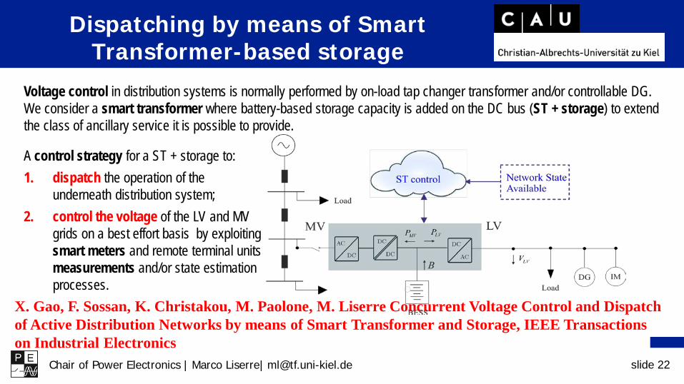
Voltage control in distribution systems is normally performed by on-load tap changer transformer and/or controllable DG. We consider a smart transformer where battery-based storage capacity is added on the DC bus (ST + storage) to extend the class of ancillary service it is possible to provide.
A control strategy for a ST + storage to:1. dispatch the operation of the
underneath distribution system;2. control the voltage of the LV and MV
grids on a best effort basis by exploiting smart meters and remote terminal units measurements and/or state estimation processes.
Dispatching by means of Smart Transformer-based storage
X. Gao, F. Sossan, K. Christakou, M. Paolone, M. Liserre Concurrent Voltage Control and Dispatch of Active Distribution Networks by means of Smart Transformer and Storage, IEEE Transactions on Industrial Electronics

Chair of Power Electronics | Marco Liserre| [email protected] slide 23
Dispatching the operation of the LV network
The power flow at the MV/LV interface follows a dispatch plan (average power flow at 5 minutes resolution) established the day before the operation.
[1] Sossan, E. Namor, R. Cherkaoui and M. Paolone, "Achieving the Dispatchability of Distribution Feeders Through ProsumersData Driven Forecasting and Model Predictive Control of Electrochemical Storage," in IEEE Transactions on Sustainable Energy, 2016.
When the control strategy is actuated (-- line), the power flow at the MV interface is as the dispatch plan (shaded profile), while it would be stochastic otherwise (- line).
Dispatch error from 350 to < 0.1 kWh/day.
A two-stage procedure based on [1]:1. Day-ahead procedure: The dispatch plan is
computed. 2. Real-time operation: The battery charge/discharge is controlled to compensate the mismatch between the dispatch plan and realization.

Chair of Power Electronics | Marco Liserre| [email protected] slide 24
Conclusions regarding integration of storagethrough ST
A control strategy for a smart transformer with integrated storage to stack the following ancillary services: dispatch the operation of the underneath distribution system; voltage control of the MV network; voltage control of the LV network.
Simulations on the 34-bus IEEE test feeder and the CIGRE reference network for LV systems. Dispatched operation is attained with an energy error < 0.1 kWh per day, the average voltage deviation
from the reference is reduced from 4.0% to 2.5% on the MV side, and 16.0% to 8.5% on the LV. Noncomplex architecture and IT infrastructure. All the control is localized at substation level, only
smart meters measurements are required from remote units.

Chair of Power Electronics | Marco Liserre| [email protected] slide 25
The technological challenges of the DC/DC converter

Chair of Power Electronics | Marco Liserre| [email protected] slide 26
Challenges of the DC-DC Stage
• High voltage Isolation• High Input voltage • High output current• Galvanic Isolation in Medium/High frequency• Power flow control – dc link control• Dc breacker feature (short circuit current
proctection)
DC-DC Stage: The most challenge stage
IsolationEfficiencyCost
Deserves more attention

Chair of Power Electronics | Marco Liserre| [email protected] slide 27
DC-DC Stage: Implementation Concept
• Low voltage/current rating semiconductors• Scalability in voltage/power• Fault tolerance capability• Reduced dV/dt and dI/dt
• Fewer number of components• High Voltage WBG devices• Simple control/communication system
Non-Modular Vs Modular

Chair of Power Electronics | Marco Liserre| [email protected] slide 28
Challenges of the DC-DC Stage
• High Voltage Isolation• Bidirectional power flow• Galvanic Isolation in Medium/High frequency• Power flow control – dc link control• Dc breacker feature (short circuit current
proctection)
DC-DC Stage: Building Block Converter
Efficiency

Chair of Power Electronics | Marco Liserre| [email protected] slide 29
Review on high efficiency dc-dc converter
Relevant converters: Phase-shift Full-Bridge Series-Resonant Converter
Dual-Active-Bridge Multiple-Active-Bridge

Chair of Power Electronics | Marco Liserre| [email protected] slide 30
Target: Efficiency
Reliability
Accurate losses modeling
Automatic design - (optimum parameter selection)
Wideband gap devices
Fault tolerant topology
Lifetime devices considerations
Series-Resonant Converter

Chair of Power Electronics | Marco Liserre| [email protected] slide 31
• Wideband-gap devices plays an important role• Design: correct parameters selection
Max Eff = 98.61%Eff (@Pmax) = 98.1%
Overview of basic dc-dc topologiessuitable to be used as a building block ofthe ST dc-dc stage
CAU Kiel dc-dc converter
Influence on efficiency:
Series-Resonant Converter
L. F. Costa, G. Buticchi, M. Liserre, Highly Efficient and Reliable SiC-based DC-DC Converter forSmart Transformer, in IEEE Transactions on Industrial Electronics

Chair of Power Electronics | Marco Liserre| [email protected] slide 32
• Extension of the DAB with 2 additonal ports
• Operation is similar to DAB
• Phase shift modulation for power transfer
• Power transfer between all ports possible:
Quadrupole Active Bridge

Chair of Power Electronics | Marco Liserre| [email protected] slide 33
Zero voltage switching range of the DAB[Alonso, 2010].
Zero voltage switching range of the QAB and reactive currents.
• ZVS range of DAB and QAB are similar under symmetrical loading
• Reactive currents are also similar under symmetrical loading
Quadrupole Active Bridge

Chair of Power Electronics | Marco Liserre| [email protected] slide 34
• Wideband-gap devices plays an important role• Design: correct parameters selection
Max Eff = 97.5%
Overview of basic dc-dc topologiessuitable to be used as a building block ofthe ST dc-dc stage
CAU Kiel dc-dc converter
Influence on efficiency:
Quadruple Active Bridge
(SiC)
Highest efficiency of a MAB converter

Chair of Power Electronics | Marco Liserre| [email protected] slide 35
DC/DC for the Smart Transformer
Dual/Quad Active Bridge Serie Resonant Converter
controlability
Voltage and current sensors
simplicity
LVDC link controlDAB VSI

Chair of Power Electronics | Marco Liserre| [email protected] slide 36
Dual/Quab Active Bridge Serie Resonant Converter
• CHB controlsthe MVDC linkand, consequenltythe LVDC link
• DAB controls the LVDC link
DC/DC for the Smart Transformer
Chair of Power Electronics | Marco Liserre| [email protected] slide 37
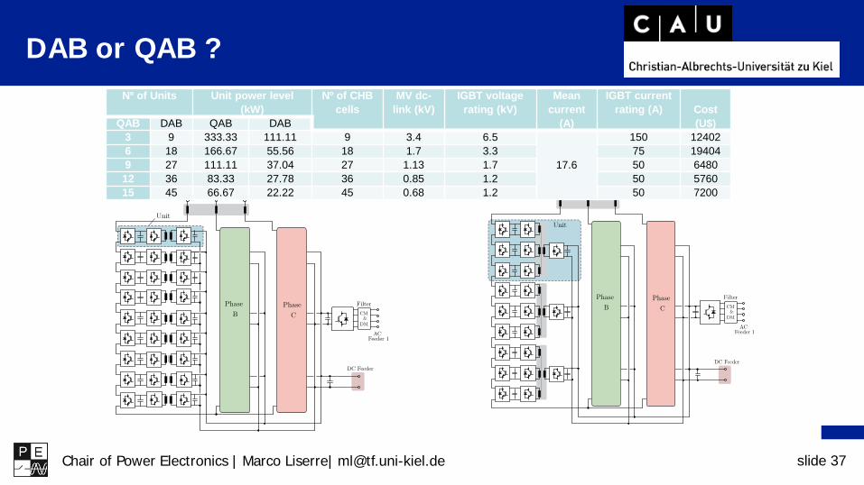
DAB or QAB ?Nº of Units Unit power level
(kW)Nº of CHB
cellsMV dc-
link (kV)IGBT voltage
rating (kV)Mean
current (A)
IGBT current rating (A) Cost
(U$)QAB DAB QAB DAB3 9 333.33 111.11 9 3.4 6.5
17.6
150 124026 18 166.67 55.56 18 1.7 3.3 75 194049 27 111.11 37.04 27 1.13 1.7 50 648012 36 83.33 27.78 36 0.85 1.2 50 576015 45 66.67 22.22 45 0.68 1.2 50 7200


Chair of Power Electronics | Marco Liserre| [email protected] slide 39
Scaled Prototype:Architecture
Three-phase converterEach phase contains:QAB converter3-Cell CHB converter
Peak power: 100kWRated power of a phase unit: 30kW

Chair of Power Electronics | Marco Liserre| [email protected] slide 40
The Smart Transformer: a grid-tailored Solid-State-Transformer
Chair of Power Electronics | Marco Liserre| [email protected] slide 41
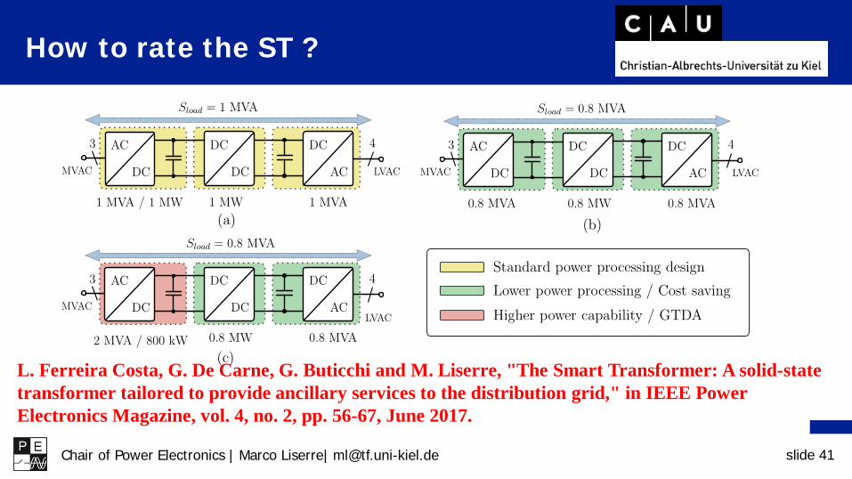
How to rate the ST ?
L. Ferreira Costa, G. De Carne, G. Buticchi and M. Liserre, "The Smart Transformer: A solid-statetransformer tailored to provide ancillary services to the distribution grid," in IEEE Power Electronics Magazine, vol. 4, no. 2, pp. 56-67, June 2017.


Chair of Power Electronics | Marco Liserre| [email protected] slide 43
Summary
• Difference between SST and ST is in functionalities
• The virtuous flow: identify, regulate, use the capacity for services
• SRC is for efficiency but for ST DAB/QAB are needed to decouple MV and LV
• A grid-tailored design means ST is not rated equally in all its stages

Chair of Power Electronics | Marco Liserre| [email protected] slide 44
Join the PhD Course
21-23 Feb 2018
Half time in Lab !