the status of superconducting linac and srf activities at the...
TRANSCRIPT

THE STATUS OF THE SUPERCONDUCTING LINAC AND SRF ACTIVITIES AT THE SNS*
S-H. Kim , # R. Afanador, W. Blokland, M. Champion, A. Coleman, M. Crofford, B. DeGraff, M. Doleans, D. Douglas, T. Gorlov, B. Hannah, M. Howell, Y. Kang, S-W. Lee, C. McMahan,
Vandygriff,ORNL, Oak Ridge, TN 37831, USA
T. Neustadt, S. Ottaway, C. Peters, J. Saunders, A. Shishlo, S. Stewart, W.H. Strong, D.
Abstract There have been substantial gains at the Spallation
Neutron Source (SNS) in the last 7 years in understanding of pulsed superconducting linac (SCL) operation including system and equipment limiting factors, and resolution of system and equipment issues. Significant effort and focus are required to assure on-going success of the operation, maintenance and improvement of the SCL, and to address the requirements of the upgrade project in the future. The SNS is taking a multi-faceted approach to maintaining and improving its linac. A balanced set of facilities which support processing, assembly, repair, and testing of cavities and cryomodules are currently being placed into service. This paper summarizes the status of the SNS SCL operation and related superconducting radio-frequency (SRF) activities such as development of ASME code-stamped spare cryomodules, R&D activities for SRF cavity performance improvements, SRF cavity development for power upgrade project, and SRF facility development/ upgrade to support all required activities.
SNS SCL STATUS Since the initial commissioning of the accelerator
complex in 2006, the SNS has begun neutron production operation and beam power ramp-up has been in progress toward the design goal. Since the design beam power is almost an order of magnitude higher compared to existing neutron facilities, all subsystems of the SNS were designed and developed for substantial improvements compared to existing accelerators and some subsystems are first of a kind. Many performance and reliability aspects were unknown and unpredictable and it takes time to understand the systems as a whole and determine the needs for additional performance improvements. From the series of tests and operational experiences more understanding of systems and their limiting conditions in the pulsed mode are being obtained at high duty operation.
The SNS SCL houses eighty-one SRF cavities in twenty three cryomodules, eleven of which are β=0.61 structures with 3 cavities in each structure, and twelve of which are β=0.81 structures with 4 cavities in each. The SNS SCL is 179-m long in the tunnel including warm quadrupole focusing sections and has 71-m long space reserved for additional 9 cryomodules for the future power upgrade. The SNS SCL is the first high-energy
proton accelerator using elliptical SRF cavities with reduced betas for the pulsed operational machine at a relatively high duty factor, which makes this accelerator a very important milestone for learning operating conditions of this type of cavities.
As reported in [1about operation of pulsed SCL, such as operating temperature, heating by electron field emission, multipacting at a various locations, higher
-4], SNS gained lots of experience
-order-mode coupler, RF control, mechanical tuners, beam loss, interlocks, machine protection systems, reliability aspects, machine availability as a user facility, etc. Through a series of commissioning campaigns, the limiting condition and the limiting gradient of each SRF cavity were identified in various operating conditions. Actual operating parameters for a stable operation required continuous update of operating gradient and settings of other supporting systems, since the stable operating condition depends on not only the operating gradients which were set based on the limiting gradients achieved, but also conditions of other supporting systems and machine conditions. The current set of cavity accelerating gradients along with all other supporting systems is providing a very stable and reliable operation of the system. The linac output energy is presently about 935 MeV and the last cavity is mostly running at zero beam-loading as an energy reserve. All linac structures are running at the full design duty factor.
SCL Operational Statistics Achieving high availability is one of the most
important aspects for user facilities. Fig. 1 shows the downtime breakdown of the sub-systems for the SCL system for three years. Each run has different issues that affect the machine availability. Fiscal Year 2013 (FY13) data is up to the end of May 2013 before the summer maintenance down period. Last three years the overall availability has been staying at about 98 %. Fig. 2 shows the detailed breakdown of the down time from the ‘cavity trip’ in Fig. 1, which represents the availability of the SRF cavities and cryomodules (SRF cavity/CM). The availability of SRF cavity/CM in FY13 is 99.85 % and that in FY12 is 99.64 %. In FY13 the RF in the linac was set for the full design duty factor, which results in more down time in FY13 in the category of ‘cavity conditioning’ than that in FY12. It is noticeable that there’s a large reduction of downtime in FY13 by ‘errant beam’ and ‘beam halo’ and/or their consequences. More
___________________________________________
* This work was supported by SNS through UT-Battelle, LLC, under contract DE-AC05-00OR22725 for the U.S. DOE # [email protected]
Proceedings of SRF2013, Paris, France MOP007
03 Operating experience with SRF accelerators
B. Project under construction
ISBN 978-3-95450-143-4
83 Cop
yrig
htc ○
2013
byth
ere
spec
tive
auth
ors
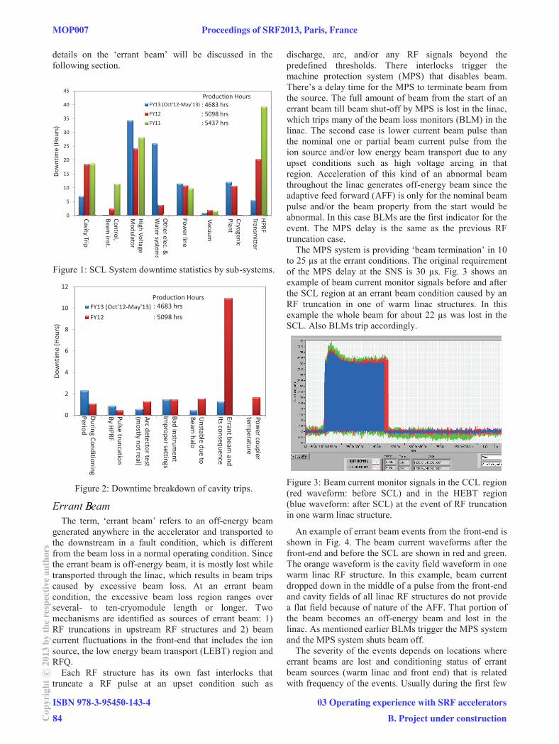
details on the ‘errant beam’ will be discussed in the following section.
Figure 1: SCL System downtime statistics by sub-systems.
Figure 2: Downtime breakdown of cavity trips.
Errant B eamBThe term, ‘errant beam’ refers to an off-energy beam
generated anywhere in the accelerator and transported to the downstream in a fault condition, which is different from the beam loss in a normal operating condition. Since the errant beam is off-energy beam, it is mostly lost while transported through the linac, which results in beam trips caused by excessive beam loss. At an errant beam condition, the excessive beam loss region ranges over several- to ten-cryomodule length or longer. Two mechanisms are identified as sources of errant beam: 1) RF truncations in upstream RF structures and 2) beam current fluctuations in the front-end that includes the ion source, the low energy beam transport (LEBT) region and RFQ.
Each RF structure has its own fast interlocks that truncate a RF pulse at an upset condition such as
discharge, arc, and/or any RF signals beyond the predefined thresholds. There interlocks trigger the machine protection system (MPS) that disables beam. There’s a delay time for the MPS to terminate beam from the source. The full amount of beam from the start of an errant beam till beam shut-off by MPS is lost in the linac, which trips many of the beam loss monitors (BLM) in the linac. The second case is lower current beam pulse than the nominal one or partial beam current pulse from the ion source and/or low energy beam transport due to any upset conditions such as high voltage arcing in that region. Acceleration of this kind of an abnormal beam throughout the linac generates off-energy beam since the adaptive feed forward (AFF) is only for the nominal beam pulse and/or the beam property from the start would be abnormal. In this case BLMs are the first indicator for the event. The MPS delay is the same as the previous RF truncation case.
The MPS system is providing ‘beam termination’ in 10 to 25 μs at the errant conditions. The original requirement of the MPS delay at the SNS is 30 μs. Fig. 3 shows an example of beam current monitor signals before and after the SCL region at an errant beam condition caused by an RF truncation in one of warm linac structures. In this example the whole beam for about 22 μs was lost in the SCL. Also BLMs trip accordingly.
Figure 3: Beam current monitor signals in the CCL region (red waveform: before SCL) and in the HEBT region (blue waveform: after SCL) at the event of RF truncation in one warm linac structure.
An example of errant beam events from the front-end is shown in Fig. 4. The beam current waveforms after the front-end and before the SCL are shown in red and green. The orange waveform is the cavity field waveform in one warm linac RF structure. In this example, beam current dropped down in the middle of a pulse from the front-end and cavity fields of all linac RF structures do not provide a flat field because of nature of the AFF. That portion of the beam becomes an off-energy beam and lost in the linac. As mentioned earlier BLMs trigger the MPS system and the MPS system shuts beam off.
The severity of the events depends on locations where errant beams are lost and conditioning status of errant beam sources (warm linac and front end) that is related with frequency of the events. Usually during the first few
0
5
10
15
20
25
30
35
40
45
FY13 (Oct'12-May'13)
FY12
FY11
Cavity Trip
Control,Beam
inst.
High Voltage
Modulator
Other elec. &
Water system
s
Power line
Vacuum
CryogenicPlant
HPRF
Transmitter
Production Hours: 4683 hrs: 5098 hrs: 5437 hrs
Dow
ntim
e (H
ours
)
0
2
4
6
8
10
12
FY13 (Oct'12-May'13)
FY12
During Conditioning
Period
Production Hours: 4683 hrs: 5098 hrs
Dow
ntim
e (H
ours
)
Pulse truncationBy H
PRF
Arc detector test(m
ostly not real)
Bad instrument
Improper settings
Unstable due to
Beam halo
Errant beam and
Its consequence
Power coupler
temperature
MOP007 Proceedings of SRF2013, Paris, France
ISBN 978-3-95450-143-4
84Cop
yrig
htc ○
2013
byth
ere
spec
tive
auth
ors
03 Operating experience with SRF accelerators
B. Project under construction

weeks after a long maintenance shut-down or during the first week of a new ion source installation, errant beam events are more frequent. The average number of errant beam events in the past had been about 30-40 times a day out of five million pulses a day. Most of errant beam events just end up with BLM trips or sometimes with small vacuum excursions. However, when similar events repeat over time, there’s a chance an errant beam could evaporate gases and a following interaction with RF could create an environment for discharge or arcing. The energy of one mini pulse (about 1 μs beam) corresponds to about 20 J. Since the beam loading in the SNS SRF cavities are high, available RF power is large enough to create a dangerous discharge. The unwanted consequences from errant beam events could be performance degradation from surface damages or newly introduced contamination in a bad place, and component damage such as ceramic windows and feed-throughs.
Figure 4: Beam current monitor signals after the front-end (green), in CCL region (red) and cavity field amplitude of on warm linac RF structure (orange).
The first noticeable degradations of SRF cavity performances were observed during the operation in 2009. After this observation there was an intense investigation on the MPS system and the MPS delay was found to be much longer than the specification as long as 300 μs or longer. In 2010 the MPS delay issue was fixed to satisfy the original specification that is 30 μs.
When cavities show performance degradations during an operation period, cavity fields needs to be lowered down or cavities have to be turned off, which requires retuning of the linac if there is an energy reserve to keep the linac output energy same or retuning the whole accelerator. In average two or three cavities showed performance degradations per one operating period that is 4.5-month long. Most performance degradations have been recovered by careful RF conditioning or thermal cycling of cryomodules during the long maintenance period, which implies that, the performance degradation was mostly caused by gaseous contamination. So far only one cavity has not recovered after thermal cycling. More expensive consequences are having damages of parts. Vacuum leaks were created at two power coupler windows presumably in 2009 and developed over time. There two cryomodules were taken out from the tunnel and power couplers were replaced. Both cases were not catastrophic failure. The leak rates are in the range of 10-6
torr/l/s. Fig. 5 shows an arc trace on the fundamental
power coupler window taken out from the cryomodule. To have better understandings on errant beam events, diagnostic tools have been added to capture all errant beam events along with the source of events. Examples are shown in Fig. 3 and Fig. 4. Errant beam could hit anywhere in the linac because there are multiple sources, all RF structures and the front end. The main focus has been aimed to minimize the frequency of the events and to shorten the MPS delay. Various efforts have been put to minimize number of events such as the front end and warm linac conditioning, routine maintenance of vacuum systems, and continuous adjustment of operating parameter for warm linac structures. Presently the frequency of errant beam events is about 10-15 times per day. To minimize the downtime from the errant beam and to minimize the further performance degradation or damages, operating gradients of SRF cavities that are showing a precursor are slightly lowered down by about 5 % proactively. BLM trip conditions have been also tightened up. Developments of new beam instrumentation to abort beam in 5-6 μs is in progress [5].
Figure 5: arcing trace (shown in the circle) on the fundamental power coupler window.
Other Subjects There has been an extensive effort to understand the
mechanism for beam loss in the SCL. Even though the amount of activation in the SNS SCL is mild, beam loss in the SCL during normal operating conditions was a big question since beam dynamic calculations do not predict any beam loss. The mechanism is nicely explained with the intra-beam stripping theory through both calculations and experiments [6].
Occasionally increments of field emission are observed from several cavities due to gaseous contamination. Most of them were recovered after thermal cycling. Every long maintenance period, two or three cryomodules are thermally cycled to recover the performance. No major unrecoverable performance degradation has been observed in the past seven years of operation, except one cavity due to the errant beam as mentioned above. There is an issue with a thermal cycling because leaks could be created or developed further during the process.
The SNS decided to remove HOM coupler feedthroughs as needed after re-evaluation in 2007 for which actual HOM characteristics of all cavities were measured, and dependencies on beam current, length, and pulse repetition rate were compared. Feedthroughs were
Proceedings of SRF2013, Paris, France MOP007
03 Operating experience with SRF accelerators
B. Project under construction
ISBN 978-3-95450-143-4
85 Cop
yrig
htc ○
2013
byth
ere
spec
tive
auth
ors

taken out and blanked off in five cryomodules that were out of the tunnel for repair. Many of them had vacuum leaks and bad electrical contacts.
Keeping an energy reserve is essential to circumvent problems that cannot be addressed during operation or to minimize a down time. Almost every run a few cavities have problems in sustaining the nominal operating gradients in various reasons such as loss of operational stability, cavity performance degradations, coupler condition changes, issues with HPRF system. Those cavities need to be turned off or those operating gradients need to be lowered down. In SNS, an unstable cavity is defined as a cavity having more than 1 trip/day for several days. At every start of a 4.5-month long operation, the linac is tuned and the last SCL cavity is kept as an energy reserve. Accelerator physics personnel are continuously improving application software for the fast retuning of the SCL [7].
SRF ACTIVITIES To ensure long-term sustainability and improvement of
the SCL system, the SNS is taking a multi-faceted approach.
Cryomodule Development The spare cryomodule for the high beta section has
been designed, fabricated, and tested by SNS personnel [8]. This is the world’s first pressure vessel code stamped cryomodule (Fig.6). The approach to the engineering design for this cryomodule was to maintain critical features of the original design such as bayonet positions, coupler positions, cold mass assembly, and overall footprint. However, this new cryomodule design was required to meet the pressure requirements put forth in 10 CFR 851: Worker Safety and Health Program. The most significant engineering change was applying Section VIII of the ASME Boiler and Pressure Vessel Code to the vacuum vessel of this cryomodule instead of the traditional designs where the helium circuit is the pressure boundary.
This cryomodule has successfully passed a series of tests in the SNS test facility and was installed during the summer outage in 2012 for the machine operation. All functions are working properly with existing systems. The achieved accelerating gradients of all 4 cavities for stable operation are 16 MV/m which exceeds the design specification. The spare cryomodule and in-house capability gained through the development will increase the long-term sustainability of the SNS SCL operation.
Figure 6: The SNS high beta spare cryomodule.
R&D for In-Situ Processing As mentioned above the linac output energy is lower
than the design output energy, 1GeV mainly due to heating effects from the electron activities in the high beta cavities. In order to reach 1-GeV operation, the electron activities in high beta cavities need to be lowered down and operating gradients of the high beta cavities need to be increased by 15 %. Rebuilding a cryomodule for performance improvements is time-consuming and expensive. The cost effective processing with minimal impact on the machine operation is preferable. Possible candidates for in-situ processing were examined for the SNS cryomodule case mainly between helium processing and plasma processing. Plasma cleaning process is chosen based on the preliminary studies conducted at SNS in 2009. R&D on plasma processing started in the middle of FY12 and aims at deploying the new in-situ technique in the linac tunnel by 2016 [9].
Cryomodule Repairs and Reworks Cryomodule repairs are required for various reasons
such as tuner repairs, removal of HOM antennas, repair of helium leak, repair of insulating vacuum leak, fundamental power coupler replacement, replacement of instruments, etc. In average one cryomodule per year is taken out from the tunnel for the repair. Fig. 7 was taken during the replacement of the fundamental power coupler.
Figure 7: Cryomodule repairs in the clean room.
Prototyping for Upgrade Project The existing cavities have some issues with HOM
couplers, materials used, and manufacturing method. New cavity design has been complete based on the lessons learned in operation. Development of the new cavity is in progress. This new cavity will serve as the basis for the power upgrade project (Fig. 8).
Cavities for the power upgrade require a power coupler with higher average power capacity, 70 kW than the original one, 48 kW. RF characteristic of the existing one is pretty satisfactory. Relatively there’s less concern with peak power capacity. The existing one was tested up to 2 MW at full travelling wave condition and tested at over 500-kW peak power with real cavity operation. Mainly thermal/mechanical design was taken into account to reduce the temperature at the inner conductor. The design and prototyping are complete and ready for testing.
MOP007 Proceedings of SRF2013, Paris, France
ISBN 978-3-95450-143-4
86Cop
yrig
htc ○
2013
byth
ere
spec
tive
auth
ors
03 Operating experience with SRF accelerators
B. Project under construction

Figure 8: High beta cavity refurbishment with new end group design.
SRF Facility Development With the required facilities in place, the SNS can
conduct its own repairs, R&D for the machine performance improvement, and the energy upgrade project with increased capability, which is a critical component in supporting a large scale user facility. A balanced set of facilities which support processing, assembly, repair, testing, and R&D of cavities and cryomodules are currently being placed into service [10]. Facilities in operation are coupler processing station, cleanroom, high pressure rinse system, test cave, and control room, which are shown in Fig. 9, 10 and 11. Recently the SRF cavity vertical test system (Fig. 12) and the cryogenic test facility (CTF) system (Fig. 13) were successfully commissioned at 4 K. The horizontal test apparatus (HTA) for the plasma processing R&D and cavity system qualifications with the helium vessel and the power coupler is under development.
Until recently, tests and research and development initiatives were serviced by the main cryogenic plant. This coupled the testing and R&D with the operation of the linac. The CTF was designed to service the vertical test area and the test cave which can house either a cryomodule or the HTA [11]. The CTF has a refrigeration capacity of 650 W at 4.4 K and liquefaction capacity of 240 l/hr. This system was commissioned in July of 2013. Additional capability will soon be added that will allow for 2K operation of these facilities. Also, a portable liquid helium Dewar fill station is being added to mitigate supply chain issues of liquid helium for the neutron instrument and sample environment areas.
Figure 9: Fundamental power coupler RF processing system.
Figure 10: High pressure Rinse in the clean room.
Figure 11: Test cavity with 4-way waveguide system.
Figure 12: Vertical test area.
Figure 13: Cryogenic test facility.
Proceedings of SRF2013, Paris, France MOP007
03 Operating experience with SRF accelerators
B. Project under construction
ISBN 978-3-95450-143-4
87 Cop
yrig
htc ○
2013
byth
ere
spec
tive
auth
ors

ACKNOWLEDGMENT Authors would like to thank all of the people that have
been involved in all of the areas in the paper.
REFERENCES [1] S-H. Kim et al, “SNS Superconducting Linac Power
Ramp-up Status,” PAC’09, Vancouver, Canada, May 2009, p. 1457 (2009).
[2] S-H. Kim, “SNS Superconducting Linac Operational Experience and Upgrade Path,” LINAC’08, Victoria, Canada, September 2008, p. 11 (2008).
[3] I. E. Campisi et al, “Status and Performance of the Spallation Neutron Source Superconducting Linac,” PAC’07, Albuquerque, NM, June 2007, p. 2502 (2007).
[4] S-H. Kim et al, “Status of the SNS Cryomodule Test,” PAC’07, Albuquerque, NM, June 2007, p. 2511 (2007).
[5] W. Blokland and C. Peters, “A New differential and Errant Beam Current Monitor for the SNS Accelerator,” submitted to International Beam Instrumentation Conference 2013 (IBIC’13), Oxford, England, September 2013.
[6] A. Shishlo et al., “First Observation of Intrabeam Stripping of Negative Hydrogen in a Superconducting Linear Accelerator,” Phy. Rev. Lett. 108, 114801 (2012).
[7] T. Gorlov, “Longitudinal Tuning of the SNS Superconducting Linac,” IPAC’12, New Orleans, LA, May 2012, p. 1290 (2012).
[8] M. Howell, “The First ASME Code Stamped Cryomodule at SNS,” IPAC’12, New Orleans, LA, May 2012, p. 2465 (2012).
[9] M. Doleans et al., “Plasma Processing R&D for the SNS Superconducting Linac RF Cavities,” TUP057, these proceedings.
[10] J. Saunders et al, “Status of SRF Facilities at SNS,” IPAC’12, New Orleans, LA, May 2012, p. 2471 (2012).
[11] M. Howell et al, “Status of Spallation Neutron Source Cryogenic Test Facility (CTF),” submitted to PAC’13, Pasadena, CA, September 2013.
MOP007 Proceedings of SRF2013, Paris, France
ISBN 978-3-95450-143-4
88Cop
yrig
htc ○
2013
byth
ere
spec
tive
auth
ors
03 Operating experience with SRF accelerators
B. Project under construction