the technology of batch degassing for hydrogen removal ... · the technology of batch degassing for...
TRANSCRIPT
The technology of batch degassing for hydrogen removal from aluminium melts utilising different rotor designs
CMYKGrey : 0 / 0 / 0 /85Red : 0 / 100 / 96 / 0
IntroductionRotary degassing of liquid aluminium alloys is a widely used commercial process to control levels of hydrogen, alkali metals and inclusions in the melt prior to casting. A comprehensive theoretical understanding of the kinetics of aluminium degassing has been established in the past twenty years. Whilst there have been some published experimental tests of degassing theory in molten aluminium, in many cases key pieces of information are not reported or determined, such that a critical assessment of the underlying theory is compromised. Similarly, practical implementation of such understanding in usable shop-floor process models has met with difficulties owing to lack of knowledge concerning some key parameters. These include the stirring intensity dissipated in the melt, and its relationship to the average gas bubble size, and the mass transfer coefficient at the free surface of the melt.
A selection of different Foseco degassing rotors have been characterised in a comprehensive experimental program. The study resulted in an Internet based simulation software for the degassing processes in foundries; the elements of this simulation are presented in this paper.
Gas porosity and inclusionsThe key attribute for early aluminium applications was primarily aesthetic, as surface porosity was unacceptable for ornamental applications. The development of the electrolytic production route and dramatic cost reductions led to an increasing range of engineering applications. Slowly, an empirical understanding emerged that certain practices applied to molten alloys could harm performances. Slow cooling of large castings could also be detrimental, or different alloys varied in their ability to fill the mould.
In foundries today we recognise two major issues of molten metal quality; gas content and inclusions. The presence of porosity became even more problematic when age hardening alloys were developed, because near surface porosity invariably blistered on the surface. Additionally, a significant loss of mechanical properties, such as tensile strength was found with increasing porosity levels.
100
200
300
6 0.5 1.0 1.5 2.0 2.5 3.0 3.5 4.0
Voids, %
Ulti
mat
e Te
nsile
Str
engt
h (M
Pa)
Figure 3. Tensile strength vs. porosity level [1]
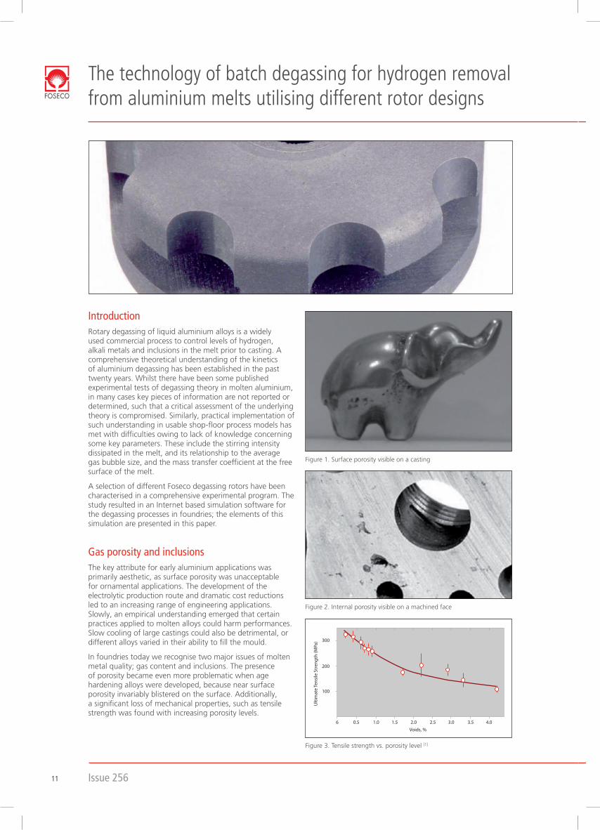
Figure 1. Surface porosity visible on a casting
Figure 2. Internal porosity visible on a machined face
Issue 25611

Figure 5. Effect of increased water vapour pressure on hydrogen solubility [2]
Figure 7. Comparison of inert gas bubble size generated by different systems [3]
Figure 6. Schematic hydrogen removal
The simple solubility equations for hydrogen in liquid aluminium need to be adapted for the alloy composition. Magnesium increases the hydrogen equilibrium solubility in liquid aluminium, whilst copper, silicon and zinc reduce the solubility levels. Modification elements such as sodium, strontium or titanium boride, at conventional addition rates, do not measurably change the hydrogen solubility. Effects that are reported relating to these elements are caused by other mechanisms; i.e. change of oxide layer thickness and surface strength, or changes in fluidity and feeding properties.
As stated before, the water vapour in air is in interaction with the melt. So the equilibrium level of hydrogen dissolved in molten aluminium should vary significantly with both ambient temperature and humidity. However, the use of gas fired burners in furnaces generates a local atmosphere which can have much higher water vapour pressures.
Hydrogen needs to be removed from the melt prior to casting with inert gases, such as argon or nitrogen being used to purge the melt. The understanding of the hydrogen removal mechanism is essential to define and influence factors for the best removal practice.
Atomic hydrogen H is dissolved in liquid aluminium and homogenously distributed. Dry inert gas bubbles are introduced into the melt with a hydrogen partial pressure inside of almost zero. Then a local equilibrium is rapidly established between H concentration in the molten boundary layer and the partial pressure of H
2 in the inert gas bubble. The diffusion of hydrogen from the bulk into the boundary layer is rate limited, whilst the recombination of atomic to
molecular hydrogen is very rapid. The hydrogen concentration in the bubble increases as it rises to the melt surface.
The rate of hydrogen transfer depends on both diffusion and the total area of bubble interface. A given inert gas flow rate will have a greater interface area for smaller bubbles. Additionally, each bubble stays longer in the melt as the bubble gets smaller, since the terminal velocity is reduced and allows longer time for hydrogen transport. A deeper reaction zone in a ladle or crucible allows more time for equilibrium because the bubble stays in the melt longer before reaching the surface.
Therefore, the design for a practical degasser needs to create the smallest bubbles low down in the treatment vessel. This is achieved at a high rotor velocity; also mixing the melt at the same time to get a homogenous hydrogen distribution.
Lance treatment was the beginning of industrial degassing, but lances tend to produce rather coarse bubbles between 10 and 50 mm in diameter with a wide bubble size distribution and offered limited melt homogenising. Porous blocks, either attached to the lance outlet or to the bottom of the furnace, create typically finer bubbles of 10 to 20 mm in diameter; but even with them, the homogenising and bubble distribution is not optimal. Eventually, the development of spinning injection systems with rotors attached solved the problem of insufficient gas distribution and delivered bubble sizes in the range of 3 to 10 mm in diameter.
Characterisation of rotor designs
Hydrogen solubility and influencing parametersThe aluminium melt is always in interaction with the atmosphere, to a point where an equilibrium is formed between gaseous hydrogen in the air and hydrogen dissolved in molten aluminium. But the partial pressure (i.e. amount) of hydrogen in the atmosphere is almost irrelevant. Therefore, the hydrogen comes from the water vapour in the atmosphere, which readily reacts with liquid aluminium to produce two problematic reaction products, i.e. alumina (inclusions) and hydrogen (gas).
2 Al (l) + 3 H2O (gas) = Al2O3 (s) + 3 H2 (gas).
Aluminium has problems with hydrogen, not because it is particularly soluble in liquid aluminium, but because it is particularly insoluble in solid aluminium and so it comes out of solution during solidification. Solubility mainly depends on the temperature of the aluminium:
200 300 400 5000 600 700 800 900
10
1
0,1
0,01
0,001
0,0001
Temperature (oC)
Hyd
roge
n co
nten
t (m
l/100
gAI)
Figure 4. Hydrogen solubility in aluminium [2]
660 680 700 720 740 760 780 800
0.50
0.45
0.40
0.35
0.30
0.25
0.20
0.15
0.10
0.05
0.00
Temperature (C)
Hydr
ogen
(mI/1
00g)
0.0750.0500.0450.0400.0350.0300.0250.0200.0150.0100.005
Theory and principals of hydrogen removal
The technology of batch degassing for hydrogen removal from
aluminium
melts utilising different rotor designs
12

The torque data as measured was converted into power being delivered into the tank.
Power = 2 p r T (T = torque)
The data is well described with a cubic dependency of rotor power on rational speed.
Power = k r³ (k = trial constant)
Utilising the power, all Foseco rotors can be compared directly with each other. The recently developed FDR and XSR rotors generate higher power than the traditional rotors. Therefore, these rotors create finer bubbles. The GBF XHT, predominantly used in the Asian foundry market, performs similarly to the best-in-class European designs.
Mixing capabilities of degasser rotors
A well designed degassing system will have two key attributes. Firstly, the melt will be rapidly mixed to achieve and maintain chemical and thermal homogeneity throughout the process. It is important that the time required to achieve good mixing is substantially less than the metal treatment time. Secondly, the turbulence generated by the rotor will result in small average size of inert gas bubbles, which the well mixed flow patterns will ensure are well distributed throughout the melt.
A further series of experiments have been undertaken to determine the mixing characteristics of each rotor under a range of operating conditions.
The same series of rotors were selected for these trials as shown in figure 8, and tested at different diameters. The trials were conducted with one baffle plate in place, a constant inert gas flow of 10 l/min and 200, 300 and 400rpm for each rotor.
FDU* SPR
MTS FDR
Diamond
FDU XSR
Star
GBF XHT
Top
Baffle Plate
LT
LM
LB
RT
BP
CB
Left Centre Right
RM
RB
Middle
Bottom
Figure 9. Locations of thermocouples in mixing tank
Power analysis of degasser rotors
All trials have been carried out in a perspex tank filled with water. A series of rotor designs were selected for these trials, summarised in figure 8, and tested at different diameters. This paper discusses trials with one baffle plate in place and a constant inert gas flow of 10 l/min.
In order to measure the power dissipated in the liquid, the torque in the rotor shaft was measured; it is not possible simply to measure the power drawn by the motor, owing to losses within the transmission system and bearings. This was achieved by coupling a torque sensor DRFL-II-30 from ETH Messtechnik GmbH in series between the motor drive and the graphite shaft and rotor. A read out unit type Value View 291-1 showed the effective torque; the stable reading at different rotor speeds was noted. It is apparent that torques at very high rotational speeds seemed to deviate from the trend at lower speeds; this is indicative that the significant aeration is starting from the free surface.
Figure 8. Rotors in trial
Issue 25613

Figure 11. Screenshot of batch degassing software
The starting screen provides sub-menus for input of
• alloycomposition
• ambientconditions
• operatingparameters
• geometryofthetreatmentvessels
• hydrogeninitiallevel
The operator can choose alloy compositions and crucible or ladle geometries from a list or input own values. Ambient conditions and operating parameters are foundry specific values, which are known or needed to optimise the degassing process. The initial hydrogen level is often unknown, but 0,3ml/100gAl is a common value and changes in this influence the curves insignificantly.
The rotor menu includes different types of rotors at various diameters. By clicking one or more rotors the degassing curves are drawn in a diagram showing hydrogen level vs. time. The model calculates the degassing performance for each chosen rotor in percentage of hydrogen removed and the average treatment gas consumption.
The input screen offers the option to use a treatment gas containing hydrogen. So there is a way to simulate upgassing processes as well.
A plotting menu enables the user to put in hydrogen levels measured with ALSPEK H electrochemical hydrogen sensor; this data can then be plotted in the diagram to compare predicted degassing curves with real foundry trial results.
Each calculation can be printed and saved for further simulations later.
Eight thermocouples type T were located in the tank at the locations indicated in figure 9. For each experiment approximately 7000g of hot water at around 80°C was added to the tank, once steady mixing conditions were established. The temperatures were logged at 100 ms intervals using an 8 channel USB TC-08 Data Logger from Pico Technology.
All plotted data was normalised and a “mixing time” had been defined. Figure 10 shows the results for different 190mm diameter rotor designs at various speeds.
At lower speeds of around 200 rpm, the FDR rotor needs about 40 seconds for effective mixing whilst other types need up to 3 times more. With increasing speed the differences between the rotor types becomes smaller. These observations are almost inline with experiences from foundry trials; FDR rotors start at a lower speed and have a good degassing performance.
The FDR rotor is seen to perform well across the board at all diameters. It generally had a significantly shorter mixing time than the XSR rotor of equivalent diameter, primarily because the FDR rotor delivers more power into the liquid at a given speed.
100 200 300 400 500
120
100
80
60
40
20
0
Rotor Speed (rpm)
Mix
ing
times
FDRXSRStarDiamond
Figure 10. Mixing time comparison for 190 mm rotors
Batch degassing softwareFoseco’s non-ferrous Marketing and Technology team have worked with Technology Strategy Consultants to develop a web-based batch-degassing model. It has been designed as a tool to quickly analyse foundries’ operations, and make suggestions for their improvement.
The mathematical model behind this software is based on the best available published information, concerning the kinetics of hydrogen degassing (e.g. hydrogen solubility, diffusivity, mass transfer rates and stable bubble sizes). An extensive program, which is discussed in this article earlier, was undertaken to provide specific information about individual rotors.
The technology of batch degassing for hydrogen removal from
aluminium
melts utilising different rotor designs
14

Figure 12. Influence of different rotor designs on degassing efficiency
Simulation variables:
Crucible type: BU 600 with 600 kg of melt
Alloy type: AlSi7Mg
Inert gas flow rate: 20 l/min
Rotor speed: 450 rpm
Rotor design: variable
Rotor diameter: 190 mm
From the parameters defined above the following conclusions can be made:
• initiallytheFDRrotordegassesmorequicklyandreached the desired hydrogen level faster
• theXSRandGBFXHTrotors,althoughquiteefficient, reach the desired hydrogen level slightly later
• thetraditionalSPRrotortakesconsiderablylongerto achieve the specified level on hydrogen
Figure 13. Influence of different rotor diameters on degassing efficiency
Simulation variables:
Crucible type: BU 600 with 600 kg of melt
Alloy type: AlSi7Mg
Inert gas flow rate: 20 l/min
Rotor speed: 450 rpm
Rotor design: XSR
Rotor diameter: variable
From the parameters defined above the following conclusions can be made:
• thelargerthediameter,thegreaterthepowergenerated and the finer the bubbles
• thelargestrotorcreatesconsiderableturbulence,which increases the regassing when hydrogen level becomes low
0 2 4 6 8 10 12
Times (min)
0.30
0.35
0.25
0.20
0.15
0.10
0.05
0.00
Hydr
ogen
con
tent
(ml/1
00gA
l)
SPR 190XSR 190FDR 190GBF XHT
0 2 4 6 8 10 12
Times (min)
0.30
0.25
0.20
0.15
0.10
0.05
0.00
Hydr
ogen
con
tent
(ml/1
00gA
l)
XSR 140XSR 190XSR 220
The following diagrams are created with the batch degasser software version 2.1 and show different influences on degassing efficiency:
Issue 25615
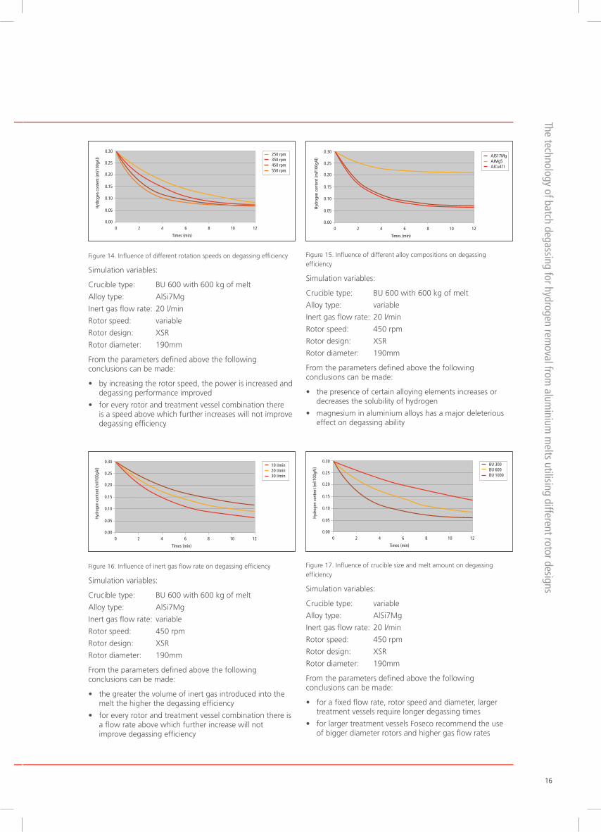
Figure 14. Influence of different rotation speeds on degassing efficiency
Simulation variables:
Crucible type: BU 600 with 600 kg of melt
Alloy type: AlSi7Mg
Inert gas flow rate: 20 l/min
Rotor speed: variable
Rotor design: XSR
Rotor diameter: 190mm
From the parameters defined above the following conclusions can be made:
• byincreasingtherotorspeed,thepowerisincreasedand degassing performance improved
• foreveryrotorandtreatmentvesselcombinationthere is a speed above which further increases will not improve degassing efficiency
Figure 15. Influence of different alloy compositions on degassing efficiency
Simulation variables:
Crucible type: BU 600 with 600 kg of melt
Alloy type: variable
Inert gas flow rate: 20 l/min
Rotor speed: 450 rpm
Rotor design: XSR
Rotor diameter: 190mm
From the parameters defined above the following conclusions can be made:
• thepresenceofcertainalloyingelementsincreasesor decreases the solubility of hydrogen
• magnesiuminaluminiumalloyshasamajordeleterious effect on degassing ability
Figure 16. Influence of inert gas flow rate on degassing efficiency
Simulation variables:
Crucible type: BU 600 with 600 kg of melt
Alloy type: AlSi7Mg
Inert gas flow rate: variable
Rotor speed: 450 rpm
Rotor design: XSR
Rotor diameter: 190mm
From the parameters defined above the following conclusions can be made:
• thegreaterthevolumeofinertgasintroducedintothe melt the higher the degassing efficiency
• foreveryrotorandtreatmentvesselcombinationthereis a flow rate above which further increase will not improve degassing efficiency
Figure 17. Influence of crucible size and melt amount on degassing efficiency
Simulation variables:
Crucible type: variable
Alloy type: AlSi7Mg
Inert gas flow rate: 20 l/min
Rotor speed: 450 rpm
Rotor design: XSR
Rotor diameter: 190mm
From the parameters defined above the following conclusions can be made:
• forafixedflowrate,rotorspeedanddiameter,larger treatment vessels require longer degassing times
• forlargertreatmentvesselsFosecorecommendtheuse of bigger diameter rotors and higher gas flow rates
0 2 4 6 8 10 12
Times (min)
0.30
0.25
0.20
0.15
0.10
0.05
0.00
Hydr
ogen
con
tent
(ml/1
00gA
l)
250 rpm350 rpm450 rpm550 rpm
0 2 4 6 8 10 12
Times (min)
0.30
0.25
0.20
0.15
0.10
0.05
0.00
Hydr
ogen
con
tent
(ml/1
00gA
l) AJS17MgAJMg5AJCu4TI
0 2 4 6 8 10 12
Times (min)
0.30
0.25
0.20
0.15
0.10
0.05
0.00
Hydr
ogen
con
tent
(ml/1
00gA
l)
10 I/min20 I/min30 I/min
0 2 4 6 8 10 12
Times (min)
0.30
0.25
0.20
0.15
0.10
0.05
0.00
Hydr
ogen
con
tent
(ml/1
00gA
l)
BU 300BU 600BU 1000
The technology of batch degassing for hydrogen removal from
aluminium
melts utilising different rotor designs
16

Conclusion and outlookThe research work undertaken is proving to be an important contributor to the understanding of hydrogen control in aluminium melts and this will improve the ability to optimise this important part of metal treatment practice.
Foseco is finding the predictions of the degassing model to reflect the reality in production foundries. The degassing model is proving to be an effective tool for analysing and optimising the degassing process.
Each particular metal treatment station requires a particular set of parameters – rotor design, diameter and rotor speed.
The model enables foundries to better understand the degassing process. They can easily compare different strategies:
• shortestdegassingtime
• increaseconsumableslife
• avoidanceofovergassing
By developing the scientific tests described earlier, Foseco has developed more efficient rotor designs which will achieve improved performance for the FDU and MTS degassing machines.
References[1] Aluminium Alloy Castings; JG Kaufman and EL Rooy (2005)
[2] The effects of Hydrogen in Aluminium and its Alloys; DEJ Talbot, Maney (2004)
[3] The treatment of Liquid Aluminium Silicon Alloys; JE Gruzleski and BM Closset, AFS (1990)
Issue 25617