the terak tester user's guide - computer · pdf filethe terak tester user's guide...
TRANSCRIPT
The Terak Tester User's Guide
Vernon L. Chi
Microelectronic Systems Laboratory
The University of North Carolina at Chapel Hill Department of Computer Science New West Hall 035 A Chapel HiD. N.C. 27514
Technical Report SS-014

V. Chi Terak Tester User's Guide page 1
1 Introduction
This document is an introduction to writing programs for chip testing using the Terak tester at the Microelectronic Systems Laboratory (MSL), at the University of North Carolina, Chapel Hill. It is intended to help you understand the testing environment and, more important, the use of the software tool Gee!.
An appendix is included which introduces the use of the hardware as well. These tools include a VAX host computer running UNIX, a Terak microcomputer running UCSD Pascal, the special tester interface and test head, and communications facilities between the VAX and the Terak.
2 Scope
This document illustrates the basics needed for using the Terak tester and how the tools are used. No attempt is made to illustrate the entire Gee! language; many test programs will only need to use a small part of it. An example is given, however, which illustrates how heavy use of Gcel can accelerate the execution of a test enormously.
For those needing the full power of Gcel, an appendix is included which presents a complete BNF description of the Gcel syntax, along with semantic annotations. A reasonable familiarity with programming and with reading of BNF should be sufficient for a user to make full use of Gee!.
3 How the software Is organised
To test your chip using the Terak tester you must write a test program. This program performs the following basic steps:
1. prepares a set of stimulus vectors (test patterns),
2. presents the stimulus vectors to the DUT (device under test) pins,
3. reads response vectors (test results) from the DUT pins,
4. stores and/or evaluates the response vectors.
These steps are performed cooperatively by a driver program and a special interface subroutine.
The driver program, written in Pascal, performs step 1 and step 4. The special subroutine, written in Gcel, performs steps 2 and 3. This subroutine is declared to be an external procedure in the driver program. These entities are compiled/ assembled independently, then linked together to create a complete test program.
In the following sections we discuss the Gcel language in detail and how the driver program and gcel subroutine communicate with each other. Those needing instruction in Pascal are referred to Jensen and Wirth [1], Wilson and Addyman [2], and in particular for UCSD Pascal, UCSD [3].
4 What Ia Geel and WhyT
4.1 What Is GeeiT
Basically, Gcel is a simple programming language, developed specifically for use with the Terak Tester. A Gee! program implements the body of an external procedure of a Pascal driver program. The Gee! procedure provides an interface between the driver program and the tester hardware as follows:
MSL
1. the driver passes an array of test vectors as a parameter to the gee! procedure;
2. Gcel "assert" statements transfer the test vectors to the outputs of the tester hardware which are connected to the DUT socket.
3. Gee! "read" statements transfer the response vectors from the inputs of the tester, which are also connected to the DUT socket, to an array.
4. Upon returning, Gee! passes the response vector array back to the driver program as a parameter. A Gee! program consists of a sequence of gcel statements. For example, some Gr.el statements, and their associated actions are:
* "assert": present a stimulus vector to the DUT pins.
* "lo", "hi": modify the states of selected DUT pins.
UNC Department of Computer Science 29 May 1985
V. Chi Terak Tester Uaer'• Guide
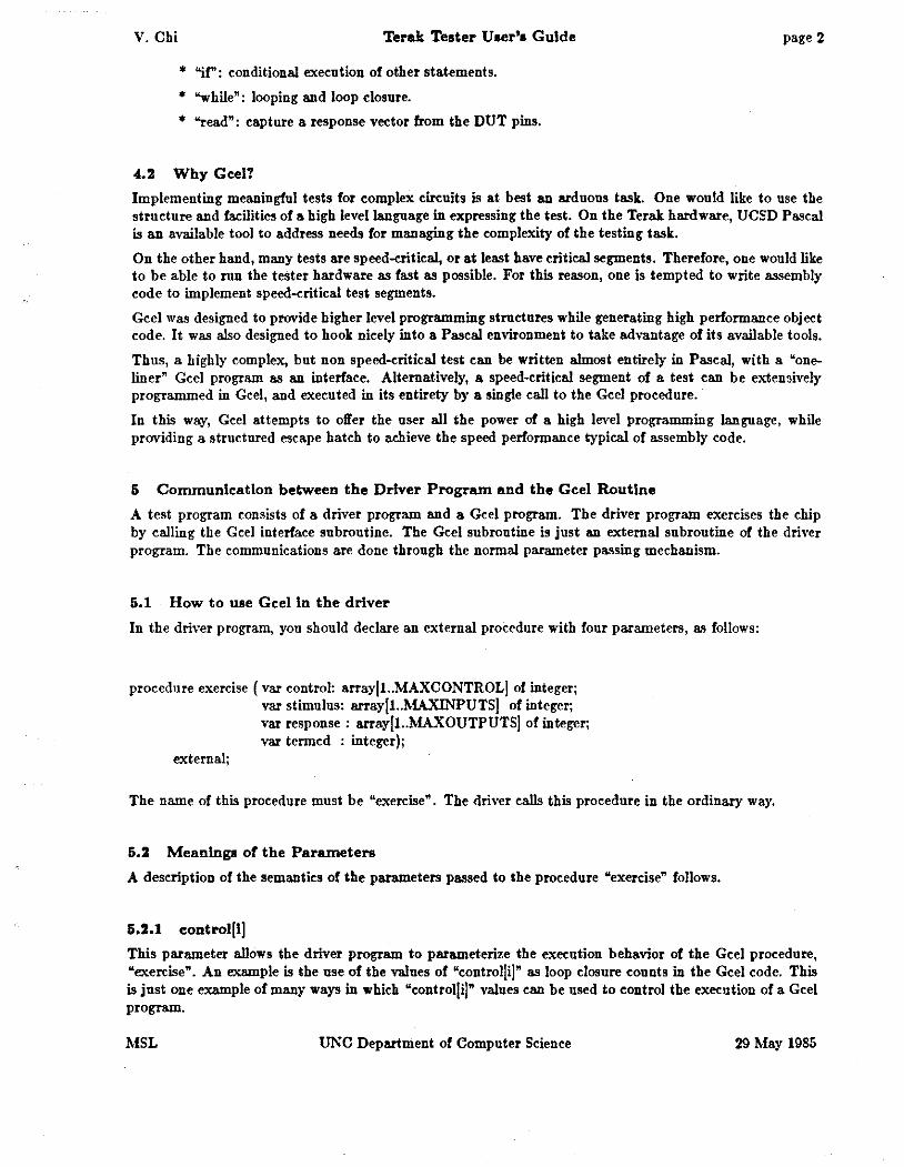
* "if": conditional execution of other statements.
* "while": looping and loop closure.
* "read": capture a response vector from the DUT pins.
4.2 Why GeelT
page 2
Implementing meaningful tests for complex circuits is at best an arduous task. One would like to use the structure and facilities of a high level language in expressing the test. On the Terak hardware, UCSD Pascal is an available tool to address needs for managing the complexity of the testing task.
On the other hand, many tests are speed-critical, or at least have critical segments. Therefore, one would like to be able to run the tester hardware as fast as possible. For this reason, one is tempted to write assembly code to implement speed-critical test segments.
Gee! was designed to provide higher level programming structures while generating high performance object code. It was also designed to hook nicely into a Pascal environment to take advantage of its available tools.
Thus, a highly complex, but non speed-critical test can be written almost entirely in Pascal, with a "oneliner" Gee! program as an interface. Alternatively, a speed-critical segment of a test can be extensively programmed in Gee!, and executed in its entirety by a single call to the Gee! procedure.
In this way, Gee! attempts to offer the user all the power of a high level programming language, while providing a structured escape batch to achieve the speed performance typical of assembly code.
5 Communication between the Driver Program and the Gee! Routine
A test program consists of a driver program and a Gee! program. The driver program exercises the chip by calling the Gee! interface subroutine. The Gee! subroutine is just an external subroutine of the driver program. The communications are done through the normal parameter passing mechanism.
5.1 How to use Gee! In the driver
In the driver program, yon should declare an external procedure with four parameters, as follows:
procedure exercise ( var control: array[l .. MAXCONTROLJ of integer; var stimulus: array[l .. MAXINPUTSJ of integer; var response : array[l..MAXOUTPUTSJ of integer; var termed : integer);
external;
The name of this procedure must be "exercise". The driver calls this procedure in the ordinary way.
5.2 Meanings of the Parameters
A description of the semantics of the parameters passed to the procedure "exercise" follows.
5.2.1 control[!]
This parameter allows the driver program to parameterize the execution behavior of the Gee! procedure, "exercise". An example is the use of the values of "control[i]" as loop closure counts in the Gee! code. This is just one example of many ways in which "control[i]" values can be used to control the execution of a Gee! program.
MSL UNC Department of Computer Science 29 May 1985
V. Chi Terak Tester U ser'• Guide
I • This is a Gee! eo de fragment • I
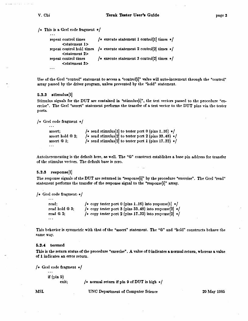
repeat control times <statement 1>
I• execute statement 1 eontrol]lj times •I
repeat control hold times I • execute statement 2 eontrol]2] times • I <statement 2>
repeat control times <statement 3>
I• execute statement 3 eontrol]2] times •I
page 3
Use of the Gcel "control" statement to aecess a "controlfi)" value will auto--increment through the "control" array passed by the driver program, unless prevented by the "hold" statement.
5.2.2 stlrnulua]l]
Stimulus signals for the DUT are contained in "stimulus]i]", the test vectors passed to the procedure "exercise". The Gee! "assert" statement performs the transfer of a test vector to the DUT pins via the tester ports.
I • Gee! code fragment • I
assert; assert hold @ 2; assert @ 1;
I• send stimulus]!] to tester port 0 (pins 1 .. 16) •I I• send stimulus]2] to tester port 2 (pins 33 . .48) •I I• send stimulusi2l to tester port 1 (pins 17 .. 32) •I
Autoincrementing is the default here, as well. The "@" construct establishes a base pin address for transfer of the stimulus vectors. The default base is zero.
5.2.3 response]!]
The response signals of the DUT are returned in "response]i]" by the procedure "exercise". The Gee! "read" statement performs the transfer of the response signal to the "response]i]" array.
I• Gee! code fragment. •I
read; read hold @ 3; read@ 2;
I• copy tester port 0 (pins 1 .. 16) into response] I] •I I• copy tester port 3 (pins 33 .. 48) into response]2j •I I• copy tester port 2 (pins 17 .. 32) into response[2] •I
This behavior is symmetric with that of the "assert" statement. The "@" and "hold" constructs behave the same way.
5.2.4 termed
This is the return status of the procedure "exercise". A value of 0 indicates a normal return, whereas a value of 1 indicates an error return.
I • Gee! code fragment • I
if(pin 9) exit; I• normal return if pin 9 of DUT is high •I
MSL UNC Department of Computer Science 29 May 1985
V. Chi Terak Tester User's Guide page (
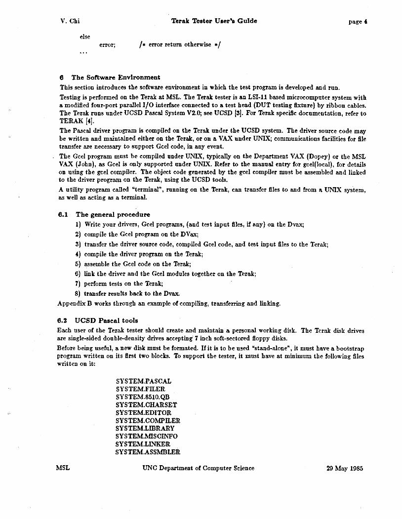
else error; /• error return otherwise •/
6 The Software Environment
This section introduces the software environment in which the test program is developed and run.
Testing is performed on the Terak at MSL. The Terak tester is an LSI-11 based microcomputer system with a modified four-port parallel 1/0 interface connected to a test head (DUT testing fixture) by ribbon cables. The Terak runs under UCSD Pascal System V2.0; see UCSD 13]. For Terak specific documentation, refer to TERAK 14]. The Pascal driver program is compiled on the Terak under the UCSD system. The driver source code may be written and maintained either on the Terak, or on a VAX under UNIX; communications facilities for file transfer are necessary to support Gee! code, in any event.
The Gee! program must be compiled under UNIX, typically on the Department VAX (Dopey) or the MSL VAX (John), as Gee! is only supported under UNIX. Refer to the manual entry for geel(loeal), for details on using the gee! compiler. The object code generated by the gee! compiler must be assembled and linked to the driver program on the Terak, using the UCSD tools.
A utility program called "terminal", running on the Terak, can transfer files to and from a UNIX system, as well as acting as a terminal.
6.1 The general procedure
1) Write your drivers, Gee! programs, (and test input files, if any) on the Dvax;
2) compile the Gee! program on the DVax;
3) transfer the driver source code, compiled Gee! code, and test input files to the Terak;
4) compile the driver program on the Terak;
5) assemble the Gee! code on the Terak;
6) link the driver and the Gee! modules together on the Terak;
7) perform tests on the Terak;
8) transfer results back to the Dvax.
Appendix B works through an example of compiling, transferring and linking.
6.2 UCSD Pascal tools
Each user of the Terak tester should create and maintain a personal working disk. The Terak disk drives are single-sided double-density drives accepting 7 inch soft-sectored floppy disks.
Before being useful, a new disk must be formated. If it is to be used "stand-alone", it must have a bootstrap program written on its first two blocks. To support the tester, it must have at minimum the following files written on it:
MSL
SYSTEM.PASCAL SYSTEM.FILER SYSTEM.8510.QB SYSTEM.CHARSET SYSTEM.EDITOR SYSTEM. COMPILER SYSTEM.LIDRARY SYSTEM.MISCINFO SYSTEM.LINKER SYSTEM.ASSMBLER
UNC Department of Computer Science 29 May 1985

V. Chi Terak Tester User'• Guide
TERMINAL. CODE FORMAT.CODE ll.OPCODES ll.ERRORS
page 5
Appendix B contains a cookbook procedure for configuring a new disk for use with the Terak tester.
6.3 Gee! and UNIX
Gee! is a compiler which is resident on a host computer running UNIX, such as the UNC Computer Science Department VAX (Dopey). A Gee! source code file, "fllename.g" is compiled to an object code file, "filename.!". The object module is actually LSI-11 assembly code which is human-readable.
All of the standard UNIX tools are available, such as the editors, version control, makefiles, etc. are available to write and maintain the Gcel source and, if desired, the Pascal source code.
Refer to Appendix B for a detailed example of the entire process of generating a complete test program.
'I Hardware Environment
This section introduces the hardware environment for chip testing.
'1.1 Description of the Terak Tester hardware
The Terak, test fixture, and the DUT (your chip) are the three basic components of the hardware configuration. The test fixture consists of a test interface card in the Terak and an external test head containing the DUT socket. The test head is connected to the interface with ribbon cables.
There are several interchangeable test heads to accommodate different packages such as 24-, 40., and 64-pin DIPs, and 84-pin PGA packages. Standard test heads for these packages are available, while custom test heads can be built by contract to the MSL. The standard test heads map the logical tester pins sequentially onto the physical pins of the DUT socket, i.e., tester pin 1 to DUT pin 1, tester pin 2 to DUT pin 2, etc. Custom fixturing with different mappings may be used if the ultimate performance is required of the tester.
The Terak is the control station on which the test program is executed. The test interface is a four port bidirectional parallel interface to the Terak Q-bus. It is accessed by the Terak as eight consecutive 16-bit words in memory; thus chips with up to 128 pins can be tested. The test program in the Terak sends signals to the interface ports. These signals then pass through the ribbon cables to the test head and finally to the pins of the DUT socket.
The DUT socket on a standard test head is a zero-insertion-force (ZIF) socket. It is typically green, and has a release lever to allow easy insertion and removal of the DUT. The lever should always be in the up position while inserting or removing a chip. Moving the lever to the down position will firmly lock the chip in place, ready for testing.
The standard test heads can accommodate any chips paekaged in DIP's up to 64 pins, and 84-pin PGAs. The heads available at this time are for 40.pin (can be used for 24-pin packages) and 64-pin DIPs, and for 84-pin PGAs. For DIPs, the standard head pins are numbered sequentially, starting with pin 1 being nearest the release lever of the ZIF soeket, an proceeding counter-clockwise. For PGAs, the pins are numbered sequentially according to the MOSIS bond-out pad specification.
Five volt power and ground are available on the test head on two banana jaeks. The red jack is +5 volt power, and the black is ground. On some test heads, further provision is made for a second ( "V .hot") power supply. Eaeh standard test head has a set of aecess points corresponding to the pins of the ZIF soeket. Power and ground connections must be made by the user by connecting the appropriate access point to these banana jacks and/or to external power source(s).
Note that the actual pin numbers as used in the testing programs are referring to the pins of the test interface. They do not refer to the pins of the ZIF socket. The mapping between these sets of pins is established by the test head wiring. The standard test heads have hidden this distinction by providing an identity mapping.
Some applications will need a custom mapping, for which a custom test head is required. If at all possible, however, the user should use the available standard test heads. ZIF soekets are in the $75 range, and there
MSL UNC Department of Computer Science 29 May 1985
V. Chi Terak Tester User'• Guide page 6
is a cost in building a special test head. While it is up to the user to cover the costs, MSL personnel can build a custom test head to specifications, or help the user to build one.
7.2 Procedure for Setting up the Chip for Testing
1) Connect the cables from the Terak to the test head: the 11 cable to the 11 socket and the 12 cable to the 12 socket, etc., making sure that the pin 1 marks of the cable plugs match those of the sockets.
2) Set the switch on the test head to the "off" position and set the release lever on the ZIF socket to the "open" (up) position.
3) Connect power supply and ground to the appropriate access pins. (Note: the power supplied by the Terak through the J1 and J2 cables is +5 volts). Be sure to make the connections to the eorreet pin• or you ean fatally damage the ehlp.
4) Plug the chip into the test socket, making sure the chip is seated properly, and that pin 1 (marked with a dot on the DIP, or at the notched end of the DIP) is adjacent to the release lever; then lock the chip in place by moving the release lever to the "closed" position. Handle the chip with care to avoid damage; a static discharge from your body to a chip's pin ean kill it.
5) Turn on the power switch.
6) Perform your tests.
'T) Turn off the power switch, open the release lever, and remove the chip from the test socket.
8 Programming Examples
The examples in this section are intended to introduce gee! constructs and driver program techniques. These examples are all rea) in the sense that they actually operate as advertised on the Terak tester. The gee! compiler as implemented under 4.2BSD UNIX will generate code which can be assembled and linked to the driver program by the Terak under the UCSD Pascal system.
The simple driver programs in examples 1 and 2 illustrate how to assemble and analyze stimulus and response vectors, and how these vectors are passed to and from the gee) procedure, "exercise".
Example 3 introduces some gee! control flow facilities which allow one to move speed-critical test segments out of the driver program, which is slow, and into the gee) procedure, which is relatively fast. A listing of the compiled gee! code, i.e. an LSI-llassembly code segment which is linkable as a UCSD Pascal procedure, is provided for the benefit of hackers desiring to analyze the gee! code generator.
Examples 4 and 5 are taken from tests which were performed on real custom VLSI circuits. Example 4 shows only the gee) code, and emphasizes how gee) was used to maximize the speed of the Terak tester. Example 5 represents how a simple gee! program can be used with a very baroque driver to enable very complex and intricate tests to be performed.
MSL UNC Department of Computer Science 29 May 1985

V. Chi Terak Teater Uaer'a Guide page 7
8.1 Example 1
This example consists of a gee! program and its associated PASCAL driver program. It implements a check of the tester drive and sense electronics and associated device llxiuring. The response analysis is intentionally kept minimal; just sufficient to illustrate how to access response vectors. This test will detect stuck-at faults and inter-pin shorts, reporting only that a fault was detected in a given port.
The Gee! Program
/• • • • • • • • • • • • • • • • • • • • • * • • • • • * • • • • • • • • • • • • • • • • • •I I• The gee! program is executed by each call of the procedure "exercise" in the driver •I I• program. In this case, stimulus and response vectors are passed as parameters, as is •I I• (automatically), a termination condition code. The control parameter is not used in this •I I• example. During compilation, the gee! program is passed through the C preprocessor, •I I• so comments such as this one can be included in the gee! text. •I !• • • • • • • • • • * • • • • • • • • • • • * • • * • • • • • • * • • * • • • • • • • • • •I
{ assert @0; assert @1; assert @2; assert @3; read @0; read @1; read @2; read @3; }
Ezplanation:
Each "assert" sends signals to a different word and each "read" reads from a different word. Each word is sixteen bits and is mapped onto sixteen pins of the OUT. The standard test head maps bits 0 .. 15 of word[O] to pins 1 .. 16 of the DUT, bits 0 .. 15 of word[1] to pins 17 .. 32 of the OUT, etc.
The order of the statements must be related to the order of the test vectors stored in the stimulus array. That is, the first vector in the array will be asserted at word[O], the second at word[1], etc. Similar comments apply to the response vector array.
The Driver Program
I• • • • * • • • • • • • • • • • • • • • • • • • • • • • • • • • • • • • • • • * • • • • • •I I• A useful feature of this driver program is the use of a variant record to specify a pin •I I • within a given port, and to cast this into an integer type for communication to the • I I• procedure "exercise" This is a convenient way to circumvent the tendency for UCSD •I I• PASCAL to interpret a most-significant pin (bit) specification as an integer sign-bit. •I I• • • • • • • • • • • • • • • • • • • • • • * • • • • • • • • • • • • • • • • • • • • • • •I
{$5+} I• UCSD compiler directive to enable swapping •I program porttest(input,output);
MSL
type control = array[1 .. 1[ of integer; vector = array[1 .. 4] of integer; pintype = record
case integer of 0: (int: integer); 1: (bit: set of 0 .. 15)
end;
UNC Department of Computer Science 29 May 1985

V. Chi
var ctrl: control; stimulus: vector; response: vector;
Terak Teater User'• Guide
portno, pinno, termeode: integer; pin: pintype;
procedure exercise (var etrl: control; var stimulus: vector; var response: vector; var termed: integer);
external;
procedure initialize; begin I• initialize •I stimulusJ1] := 0; stimulusJ2] := 0; stimulusJ3] := 0; stimulusJ4] := 0; writeln('This is a program to test the test head and pin drive'); writeln('electronics. You may select any (port-number, pin-number)'); writeln('pair to test, within valid range (ports: 1 .. 4; pins: 1 .. 16).'); writeln('To terminate test, select out of range (e.g. port 0).'); writeln; end; I• initialize •I
procedure dotest; var i: integer; begin I• dotest •I stimulusJportno] := pin.int; exercise( ctrl, stimulus, response, termeode ); if termcode <> 0 then
writeln('Gcel execution error.') else for i := 1 to 4 do
if stimulusJi] <> responseJi] then writeln(' Fault detected in port', i, '.');
end; I• dotest •I
begin I• porttest •I initialize; write('Enter port number and pin number to be tested: '); readln(portno, pinno); while (portno >= 1) and (portno <= 16) and (pinno >= 1) and (pinno <= I6) do
begin pin. bit:= Jpinno- I]; dotes!; pin. bit := 1 J; dotes!; writeln; write('Enter next port and pin number: '); readln(portno, pinno); end;
end. I • port test • I
8.2 Example 2
page 8
This is a gee! program used to test a 40-pin test head. li is similar to example I, but shows another feature of the gee! language: declaration of ensembles of pins to be driven or sensed as groups.
The Gee! Program
MSL UNC Department of Computer Science 29 May I985

V. Chi Terak Tester User's Guide
I• • • • • • • • • • • • • • • • • • • • • • • • • • • • • • • • • • • • • • • • • • • • * •I /• If we were to delete the "asseri @3" and "read @3" of the Gee! program in example 1, •/ /• it would become equivalent to this program. •I I• • • • • • • • • • • • • • • • • • • • • • • • • • • • • • • • • • • • • • • • • • • • • •I
stimulus response
{
40 40
assert; read; };
pins; pins;
E%planalion:
page 9
The example here shows the "stimulus" and "response" declarations. These declarations tell the Gee! compiler that when we use an asseri or read statement, we want to operate on all 40 pins together. Without these declarations, we must asseri 3 times and read 3 times to accomplish the same thing.
While we assert signals to all 40 pins by one gee! "asseri" statement, the driver program must assemble a 3-byte array of test vectors in the correct order in the stimulus array. Similarly, the single gee! "read" passes a 3-byte array back to the driver program.
The Driver Program
{$S+}
!• • • • • • • • • • • • • • • • • • • • • • • • • • • • • • • • • • • • • • * • • • • • • •I I• The use of the variant record is extended here to aid in the formatting of signals for •I I• the entire 40-pin group. Note that use of the variant record to east types exhibits •I I• implementation-dependent behavior. On the Terak tester, UCSD Pascal maps the •I I• "set" type onto the "integer array" type in the appropriate order. •I I• • • • • • • • • • • • • • • • • • • • • • • • • • • • • • * • • • • • • • • • • • • • • •I
program tst40pin(input,output);
MSL
const msb = 39; I• bit corresponding to pin 40 •I
type control = array[1 .. 1] of integer; vector = array[l..3] of integer; pintype = record
case integer of 0: (vect: vector); 1: {bits: set of O •• msb)
end; var ctrl: control;
stim, resp: pintype; bitnum, termcode: integer;
procedure exerci•e (var ctrl: control; var stimulus: vector; var response: vector; var termed: integer);
external;
procedure initialize; begin I• initialize •I writeln('This program tests a 40-pin test head and pin drive'); writeln{'electronics. It uses a "marching one/zero" test'); writeln('pattern to detect stuck-at and other faults.');
UNC Department of Computer Science 29 May 1985
V. Chi Terak Tester User's Guide
writeln; end; I• initialize •I
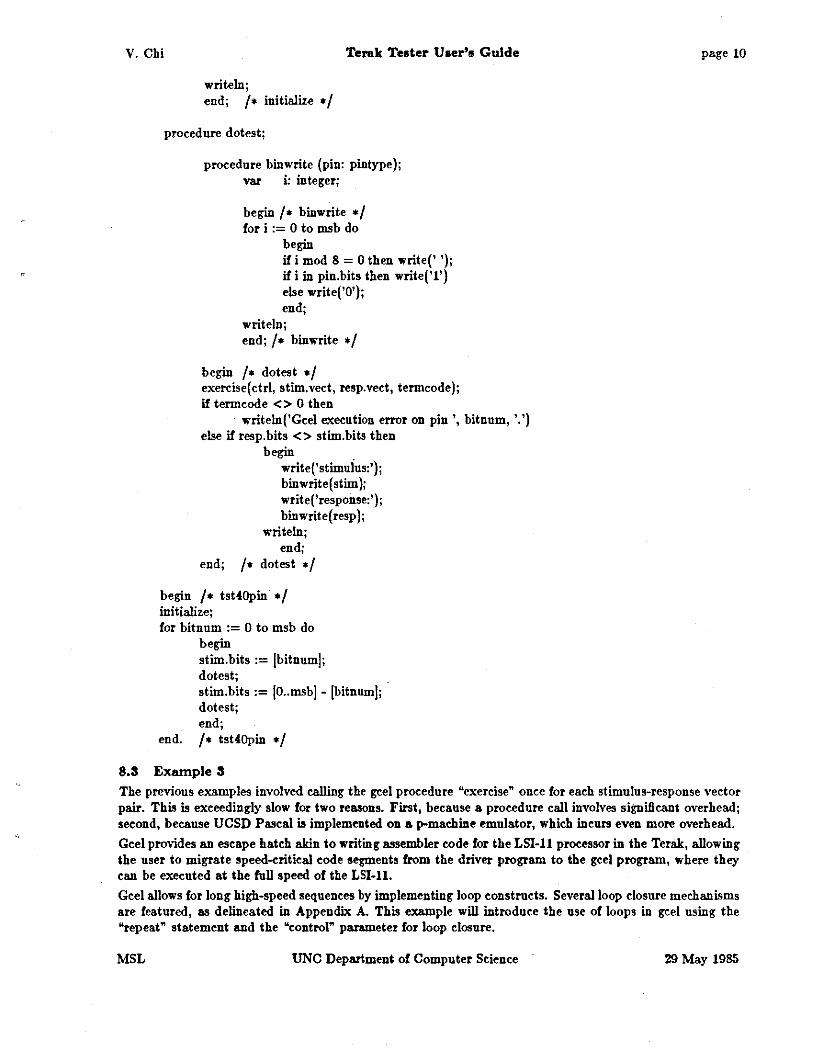
proeednre dotest;
procedure binwrite (pin: pintype); var i: integer;
begin I • binwrite *I for i := 0 to msb do
begin if i mod 8 = 0 then write(' '); if i in pin.bits then write('l') else write('O'); end;
writeln; end; I• binwrite •I
begin I• dotest •I exercise(ctrl, stim.vect, resp.vect, termcode); if termeode <> 0 then
writeln('Geel exeeution error on pin', bitnum, '.') else if resp.bits <> stim.bits then
begin write('stimuius:'); bin write( stim ); write('response:'); binwrite(resp);
writeln; end;
end; I• dotest •I
begin I• tst40pin •I initialize; for bitnum := 0 to msb do
begin stim.bits := lbitnum!; dotest; stim.bits := !O .. msb] - lbitnuml; dot est; end;
end. I • tst40pin • I
8.3 Example 3
page 10
The previous examples involved ealling the gee! procedure "exerdse" onee for eaeh stimulus-response veetor pair. This is exceedingly slow for two reasons. First, beeause a proeedure eall involves signilleant overhead; seeond, beeause UCSD Paseal is implemented on a p-ma<:hine emulator, whi<:h ineurs even more overhead.
Gee! provides an eseape hateh akin to writing assembler eode for the LSI-11 processor in the Terak, allowing the user to migrate speed-eritieal eode segments from the driver program to the gee! program, where they ean be exeeuted at the full speed of the LSI-11.
Gee! allows for long high-speed sequenees by implementing loop eonstruets. Several loop elosure mechanisms are featured, as delineated in Appendix A. This example will introduee the use of loops in gee! using the "repeat" statement and the "eontrol" parameter for loop elosure.
MSL UNC Department of Computer Seienee 29 May 1985
V. Chi Terak Teater U•r'• Gulde page 11
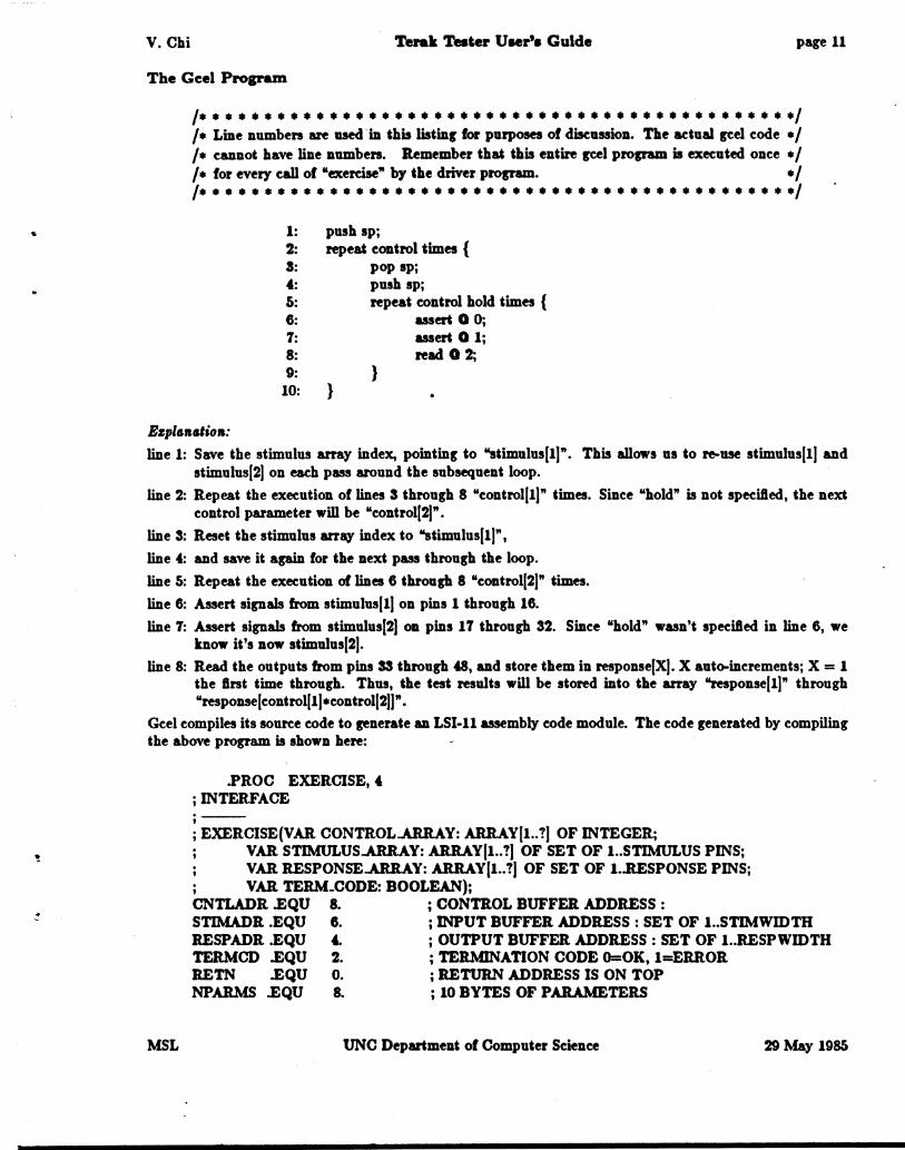
The Geel Program
I• • • • • • • • • • • • • • • • • • • • • • • • • • • • • • • • • • • • • • • • • • • • • •I I• Line numbers are used in this listing for purposes of diseuuion. The adual geel code •I I• cannot have line numbers. Remember that this entire geel program is executed once •I I• for every call of "exercise" by the driver program. •I I• • • • • • • • • • • • • • • • • • • • • • • • • • • • • • • • • • • • • • • • • • • • • •I
1: push sp; 2: repeat control times { 3: pop sp; 4: push sp; 5: repeat control hold times { 6: assert 0 0; 7: assert 0 1; 8: read 0 2; 9: }
10: }
Ezpla•alioa:
line 1: Save the stimulus array index, pointing to "stimulus(!)". This allows us to re-use stimulus(!) and stimulus(2) on each pass around the subsequent loop.
line 2: Repeat the execution of lines 3 through 8 "control(!)" times. Since "hold" is not speciled, the next control parameter will be "control(2]".
line 3: Reset the stimulus array index to "stimulus( I]",
line 4: and save it again for the next pass through the loop.
line 5: Repeat the execution of lines 6 through 8 "control(2)" times.
line 6: Assert signals from stimulus(!) on pins 1 through 16.
line 7: Assert signals from stimulus(2] on pins 17 through 32. Since "hold" wasn't speciled in line 6, we know it's now stimulus(2].
line 8: Read the outputs from pins 33 through 48, and store them in response(X). X auto-increments; X= 1 the flrst time through. Thus, the test results will be stored into the array "response(!)" through "response(control(l)•control(2)]".
Gcel compiles its source code to Kenerate an LSI-11 assembly code module. The code generated by compiling the above program is shown here:
MSL
.PROC EXERCISE, 4 ;INTERFACE ;--; EXERCISE(VAR CONTROL.ARRAY: ARRAY(! .. ?) OF INTEGER;
VAR STIMULUS.ARRAY: ARRAY(! .. ?) OF SET OF !..STIMULUS PINS; VAR RESPONSE.ARRAY: ARRAY(! .. ?) OF SET OF ! . .RESPONSE PINS; VAR TERM-CODE: BOOLEAN);
CNTLADR .EQU 8. ; CONTROL BUFFER ADDRESS : STIMADR .EQU 6. ; INPUT BUFFER ADDRESS : SET OF l .. STIMWIDTH RESPADR .EQU 4. ; OUTPUT BUFFER ADDRESS : SET OF l .. RESPWIDTH TERMCD .EQU 2. ; TERMINATION CODE O=OK, !=ERROR RETN .EQU 0. ; RETURN ADDRESS IS ON TOP NPARMS .EQU 8. ; 10 BYTES OF PARAMETERS
UNC Department of Computer Science 29 May 1985
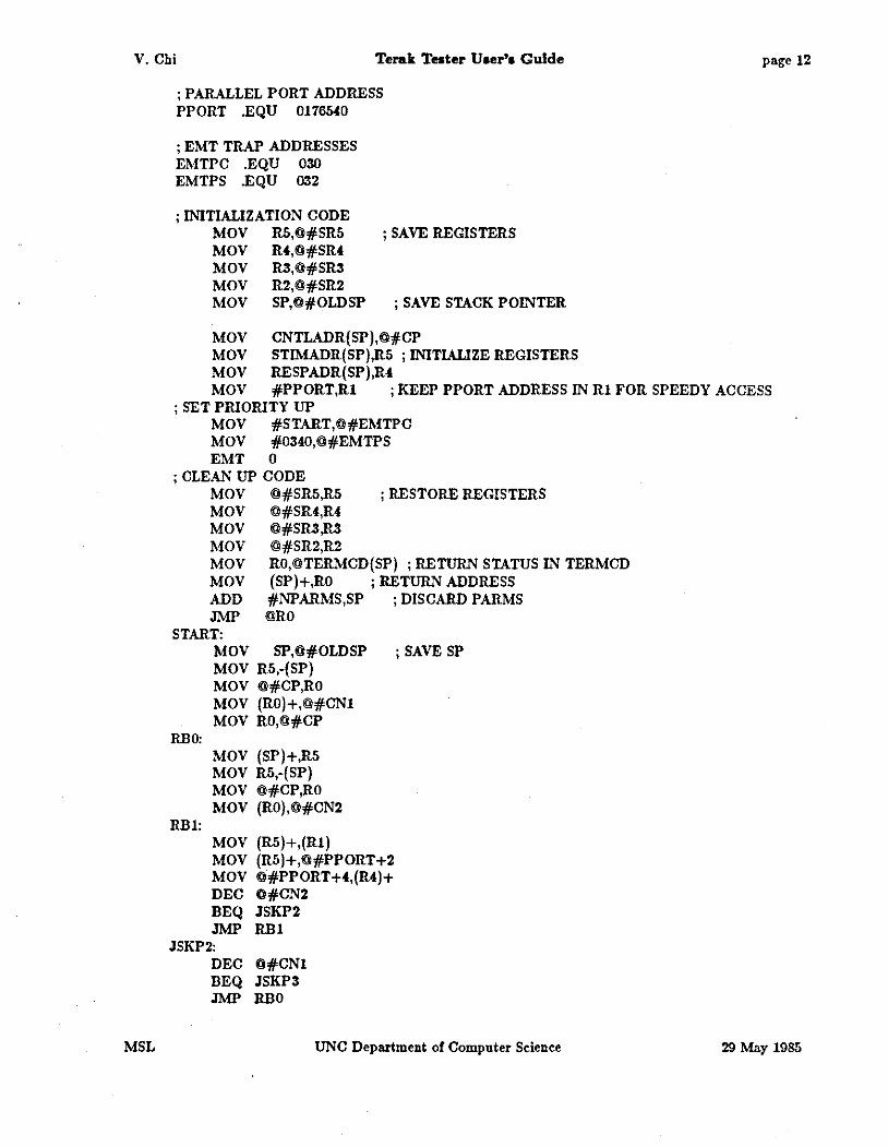
V. Chi Terak Teater Uaer'a Guide
; PARALLEL PORT ADDRESS PPORT .EQU 0176540
; EMT TRAP ADDRESSES EMTPC .EQU 030 EMTPS .EQU 032
; INITIALIZATION CODE MOV R5,@#SR5 ; SAVE REGISTERS MOV R4,@#SR4 MOV R3,@#SR3 MOV R2,@#SR2 MOV SP,@#OLDSP ; SAVE STACK POINTER
MOV CNTLADR(SP),O#CP MOV STIMADR(SP),R5 ; INITIALIZE REGISTERS MOV RESPADR(SP),R4
page 12
MOV #PPORT,Rl ; KEEP PPORT ADDRESS lN R1 FOR SPEEDY ACCESS
MSL
; SET PRIORITY UP MOV #START,@#EMTPC MOV #0340,@#EMTPS EMT 0
; CLEAN UP CODE MOV @#SR5,R5 ; RESTORE REGISTERS MOV @#SR4,R4 MOV @#SR3,R3 MOV @#SR2,R2 MOV RO,@TERMCD(SP) ; RETURN STATUS lN TERMCD MOV (SP)+,RO ; RETURN ADDRESS ADD #NPARMS,SP ; DISCARD PARMS JMP @RO
START:
RBO:
RB1:
MOV SP,O#OLDSP ; SAVE SP MOV R5,-(SP) MOV @#CP,RO MOV (RO)+,@#CNl MOV RO,@#CP
MOV (SP)+,R5 MOV R5,-(SP) MOV @#CP,RO MOV (RO),@#CN2
MOV (R5)+,(R1) MOV (R5)+,@#PPORT+2 MOV @#PPORTH,(R4)+ DEC O#CN2 BEQ JSKP2 JMP RB1
JSKP2: DEC @#CNl BEQ JSKP3 JMP RBO
UNC Department of Computer Sdenee 29 May 1985
V. Chi
JSKP3: MOV
EXIT: MOV RTI
;DATA AREA
#O,RO
O#OLDSP,SP
OLDSP .WORD SRS .WORD SR4 .WORD SR3 .WORD SR2 .WORD CNl .WORD CN2 .WORD CN3 .WORD CN4 .WORD CNS .WORD T .WORD CP .WORD
.END
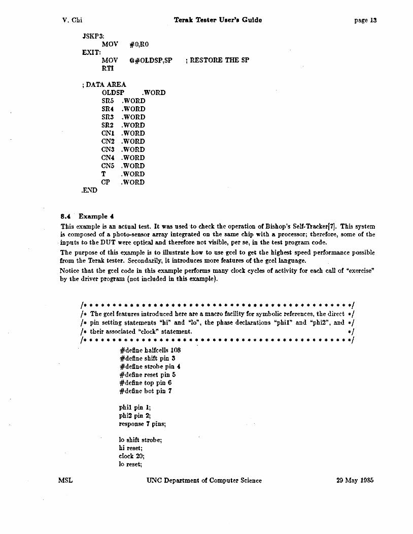
8.4 Example 4
Terak Tester User's Guide page 13
; RESTORE THE SP
This example is an actual test. It was used to check the operation of Bishop's Self. Tracker[7]. This system is composed of a photo-sensor array integrated on the same chip with a processor; therefore, some of the inputs to the DUT were optical and therefore not visible, per se, in the test program code.
The purpose of this example is to illustrate how to use gee! to get the highest speed performance possible from the Terak tester. Secondarily, it introduces more features of the gee! language.
Notice that the gee! code in this example performs many clock cycles of activity for each call of "exercise" by the driver program (not included in this example).
MSL
I• • • • • • • • • • • • • • • • • • • • • • • • • • • • • • • • • • • • • • • • • • • • • •I I• The gee! features introduced here are a macro facility for symbolic references, the direct •I I• pin setting statements "hi" and "lo", the phase declarations "phil" and "phi2", and •I /• their associated "clock" statement. •/
I• • • • * • • • • • • • • • • • • • • • • • • • • • • • • • • • • • • • • • • • • • • • • •I #define halfcells 108 #define shift pin 3 #define strobe pin 4 #define reset pin 5 #define top pin 6 #define bot pin 7
phil pin 1; phi2 pin 2; response 7 pins;
lo shift strobe; hi reset; dock 20; lo reset;
UNC Department of Computer Science 29 May 1985

V. Chi
Ezplt>n11tion:
dock control; hi strobe; dock 10; lo strobe; clock 10;
Terak Tester User's Guide
repeat halfcells times { read; hi shift; clock 10; lo shift; clock 10; }
hi reset;
page 14
Macros: Gee! code is first passed through the C pre-processor. Thus, all of its macro facilities are available. This example shows the use of the "define" facility to provide mnemonic references to pins of the DUT. Other facilities, such as file inclusion, parameterized macros, and conditional definitions are also provided. Refer to the UNIX manual IS! entries for "cc(l)" and "m4(1)" and to Kernighan and Ritchiel6j, for detailed information regarding the pre-processor.
Setting pins: Gee! allows immediate, in-line specifications for setting specific pins high and low. A "hi" ("lo") command foUowed by a pin list (terminated by a ";") will set the listed pins high (low) without affecting any unreferenced pins.
Clocking: Gee! provides automatic dock generation for two phase non-overlapping clocks. The dock phases are bound to pin numbers using the "phil" and "phi2" declarations. The "clock" statement causes phase 1 to be driven high, then low, then phase 2 high, then low. The value foUowing "clock" specifies the number of repetitions of this clock cycle to execute.
MSL UNC Department of Computer Science 29 May 1985

V. Chi Terak Tester User'• Guide page 15
8.5 Example 5
This a complete working example. It was used to test Pixel·Planes chips preparatory to integration of the chips into the (now functioning) experimental system. While much of the driver program may not be of general interest, it is included both for completeness, and to give the reader a flavor of how a very complex and involved test can be supported by the Terak Tester.
In this case, a simple Gee! procedure is used. The test is designed to demonstrate logical correctness, and was not speed-critical. The complexity of the test itself was therefore managed better in the Pascal driver, which is exactly how it was done.
This strategy separates test data generation from the actual testing. The stimulus array is read from external files. The test responses along with the input vectors are written onto an output file. This mechanism allows communication between a simulator and the tester. The simulator generates pre-processed test data, while the driver program performs the running of the test.
8.5.1 The Gee! program
#define phil pin 31 #define phi2 pin 30 #define pxl pin 29 #define px2 pin 28
stimulus response
31 9
repeat control times { assert; hi phil pxl; lo phil pxl; hi phi2 px2; lo phi2 px2; read @2; };
8.5.2 The Driver Program
pins; pins;
I• * * * * * * * * * • * * * * * • • * • * • * • * • * * • * * * • * • • • * * * * *· • * * •I I• Driver Program for chip testing: aceepts data from an input data file, generates control •I I• and stimulus vector arrays with proper values, executes the "exercise" procedure, reads •I I• back response vectors and prints the input data and the test results in a useful format •I I• • • • • • * • • • • • • • • • • • • • • • • • • • • • • • • • • • • • • • • • • • • • • •I
program pxpl30test();
const ArraySize = 2000; HalfSize = 1000; CASize = 800; ComLine = SO;
type Cnt!Array = array[l .. lj of integer;
MSL UNC Department of Computer Science 29 May 1985
V. Chi Terak Tester Uaer'• Guide
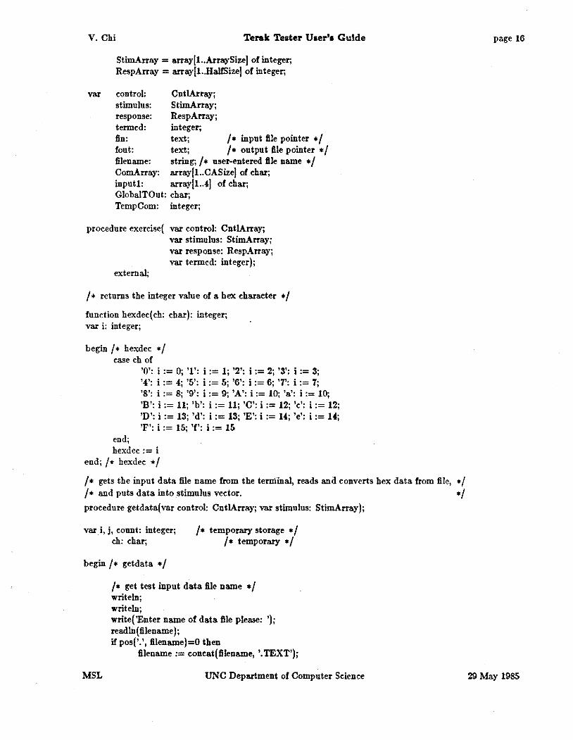
StimArray = array[l..ArraySize[ of integer; RespArray = array[l . .HalfSize[ of integer;
var control: Cnt!Array; stimulus: StimArray; response: RespArray; termed: integer; fin: text; I• input file pointer •I font: text; I• output file pointer •I filename: string; I• user-entered file name •I ComArray: array[l..CASize[ of char; inputl: array[l..4[ of char; GlobalTOut: char; TempCom: integer;
procedure exercise( var control: CntlArray; var stimulus: StimArray; var response: RespArray; var termed: integer);
external;
I• returns the integer value of a hex character •I function hexdec(eh: char): integer; var i: integer;
begin I• hexdee •I ease eh of
end;
'0': i := 0; '1': i := 1; '2': i := 2; '3': i := 3; '4': i := 4.; '5': i := 5; '6': i := 6; '7': i := 7; '8': i := 8; '9': i := 9; 'A': i := 10; 'a': i := 10; 'B': i := 11; 'b': i := 11; 'C': i := 12; 'c': i := 12; 'D': i := 13; 'd': i := 13; 'E': i := 14; 'e': i := 14; 'F': i := 15; 'f': i := 15
hexdee := i end; I• hexdee •I I• gets the input data file name from the terminal, reads and converts hex data from file, •I I• and puts data into stimulus vector. •I procedure getdata(var control: CntlArray; var stimulus: StimArray);
var i, j, count: integer; ch: char;
I• temporary storage •I I • temporary • I
begin I• getdata •I
MSL
I• get test input data file name •I writeln; writeln; write( 'Enter name of data file please: '); readln(filename); if pos('.', filename)=O then
filename:= eoneat{filename, '.TEXT');
UNC Department of Computer Science
page 16
29 May 1985

V. Chi Terak Teater User'• Guide
MSL
reset(fin, filename);
writeln; write ('processing begins .');
j := 1; while not eof(fin) do
begin I• avoid looping •I if (j > ArraySize) then
begin dose( fin); exit(getdata) end;
I• skip comments •I if (j = 1) then read( fin, ch); while (ch = 'I') do
begin readln(fin); read(fln, ch) end;
I• read in the first stimulus vector, put into inputl[[ •I inputllll := ch; i :== 2; while not eoln(fin) do
begin read(fin, ch); inputl[i[ := ch; i := i + 1 end;
I• convert hex input vector in input1[j to integer and put it into stimulus[! •I stimulus!i! := 0; i := 1; while (i < 5) do
begin stimulusU! := stimulusU! • 16 + hexdec(inputl[i!); i := i + 1 end;
I • read in the second stimulus vector, put into input2[j • I i := 1; readln(fin); while not eoln(fln) do
begin read(fln, ch); input2[il := ch; i := i + 1 end;
UNC Department of Computer Science
page 17
29 May 1985

V. Chi Terak Teeter Uaer'a Guide
j := j + 1; stimulus[ij := 0; /• convert hex input veetor in input2jj to integer
and put it into stimulus[! •/ i := 1; while (i < S) do
begin stimulusUI := stimulusUI • 16 + hexdee(input2jij); i := i + 1 end;
I• ignore the response vector- a string of integers •I read in (fin); while not eoln(fin) do read(fln, ch); read in (fin); read(fin, ch);
j := j + 1; end;
write (' processing complete'); dose( fin);
control[lj := j div 2;
end; I• getdata •I function deehex(number : integer): char; var ch: char; begin
case number of
end;
0: ch := '0'; 1: ch := '1'; 2: ch := '2'; 3: ch := '3'; 4: ch := '4'; 5: ch := '5'; 6: ch := '6'; 7: ch := '7'; 8: ch := '8'; 9: ch := '9'; 10: ch := 'A'; 11: ch := 'B'; mch:=U;U:ch:=~~M:ch:=~';1~ch:=T'
dechex := ch end; I• dechex •I
I• print the parameter- number in hex to the output file •I procedure pstring(number: integer); var i, temp: integer;
begin
MSL
NegNum: boolean; TempStr: arrayjl..4j of ehar;
I• convert the number into hexdeeimal •/ i := 1; if (number < 0) then
begin
else
NegNum := true; number := number + 32767 + 1; end
UNC Department of Computer Science
page 18
29 May 1985

V. Chi Terak Tester User'• Guide
end;
NegNum := false;
while (i < 5) do begin
end;
i := 1;
if (NegNum and (i = 4)) then temp := (number + 8) mod 16
else temp := number mod 16;
TempStr[i[ := deehex(temp); number := number div 16; i := i + 1
while (i < 5) do begin
end
write(fout, TempStr[5- i[); i := i + 1
I • print eomment from position Sta.rtPos to the output file • I proeedure pcomment(Sta.rtPos: integer); var i, Temp: integer;
begin
end;
if (StartPos = 1) then write (font, ' [ ')
else write (font, ' [ ');
if (TempCom > Sta.rtPos + 49) then Temp := Sta.rtPos + 49
else Temp := TempCom;
i := StartPos; while (i <= Temp) do
begin write(fout, ComArray[i[); i := i + 1 end
proeedure printout(var response: RespArray; var j: integer); var i, Temp: integer;
begin
MSL
I• print input data- lsi line of output •/ i := 1; while (i < 5) do
begin
UNC Department of Computer Seienee
page 19
29 May 1985
V. Chi Terak Tester User's Guide
MSL
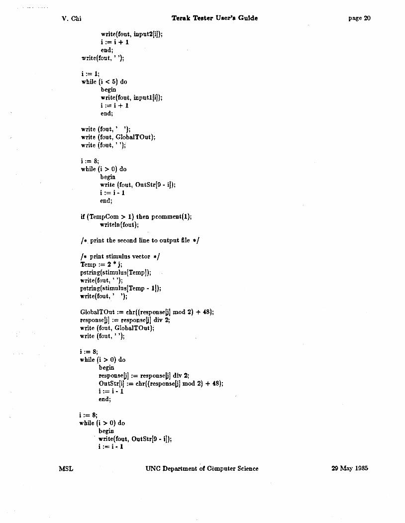
write(fout, input2[i]); i := i + 1 end;
write(fout, ' ');
i := 1; while (i < S} do
begin write(fout, inputl[i]); i := i + 1 end;
write (fout, ' '); write (font, GlobalTOut); write (font, ' ');
i := 8; while (i > 0} do
begin write (fout, OutStr[9- i]); i := i- 1 end;
if (TempCom > 1} then pcomment(1); writeln(fout);
I • print the second line to output file • I
I• print stimulus vector •I Temp:= 2 * j; pstring(stimulus[Tempj); write(fout, ' '); pstring(stimulus[Temp- 1]); write(fout, ' ');
GlobalTOut := chr((responseU! mod 2) + 48); responseU! := responseU! div 2; write (fout, GlobalTOut); write (fout, ' ');
i := 8; while (i > 0} do
begin responseU! := responseU! div 2; ?nt~tr[ij := chr( (responseU! mod 2} + 48); I := I- 1 end;
i := 8; while (i > 0} do
begin · write(fout, OutStr[9 - i!);
i := i- 1
UNC Department of Computer Science
page 20
29 May 1985
V. Chi Terak Tester User's Guide
end;
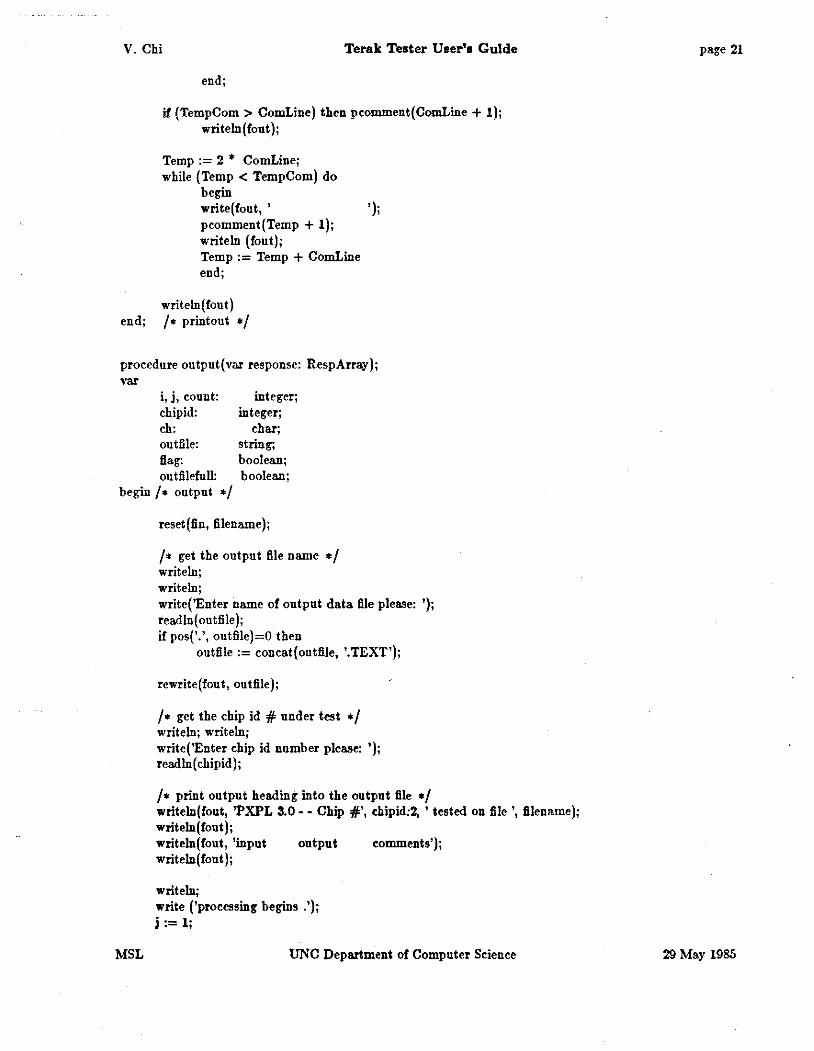
if (TempCom > ComLine) then pcomment(ComLine + 1); writeln(fout);
Temp := 2 * ComLine; while (Temp < TempCom) do
begin write(fout, ' '); pcomment(Temp + 1); writeln (font); Temp := Temp + ComLine end;
writeln(fout) end; I • printout • I
procedure output(var response: RespArray); var
i, j, count: chipid: ch: out file: flag: outfilefull:
integer; integer;
char; string; boolean; boolean;
begin I• output •I
MSL
reset(fin, filename);
I• get the output file name •I writeln; writeln; write('Enter name of output data file please: '); read In( outfile ); if pos('.', outfile)=O then
outfile := concat(outfile, '.TEXT');
rewrite (fou t, ou tfile);
I• get the chip id #under test •/ writeln; writeln; write('Enter chip id number please: '); readln(chipid);
I• print output heading into the output file •I writeln(fout, 'PXPL 3.0-- Chip #', chipid:2, 'tested on file', filename); writeln(fout); writeln(fout, 'input output comments'); writeln(fout);
writeln; write ('processing begins .'); j := 1;
UNC Department of Computer Science
page 21
29 May 1985
V. Chi
MSL
Terak Tester User'• Guide
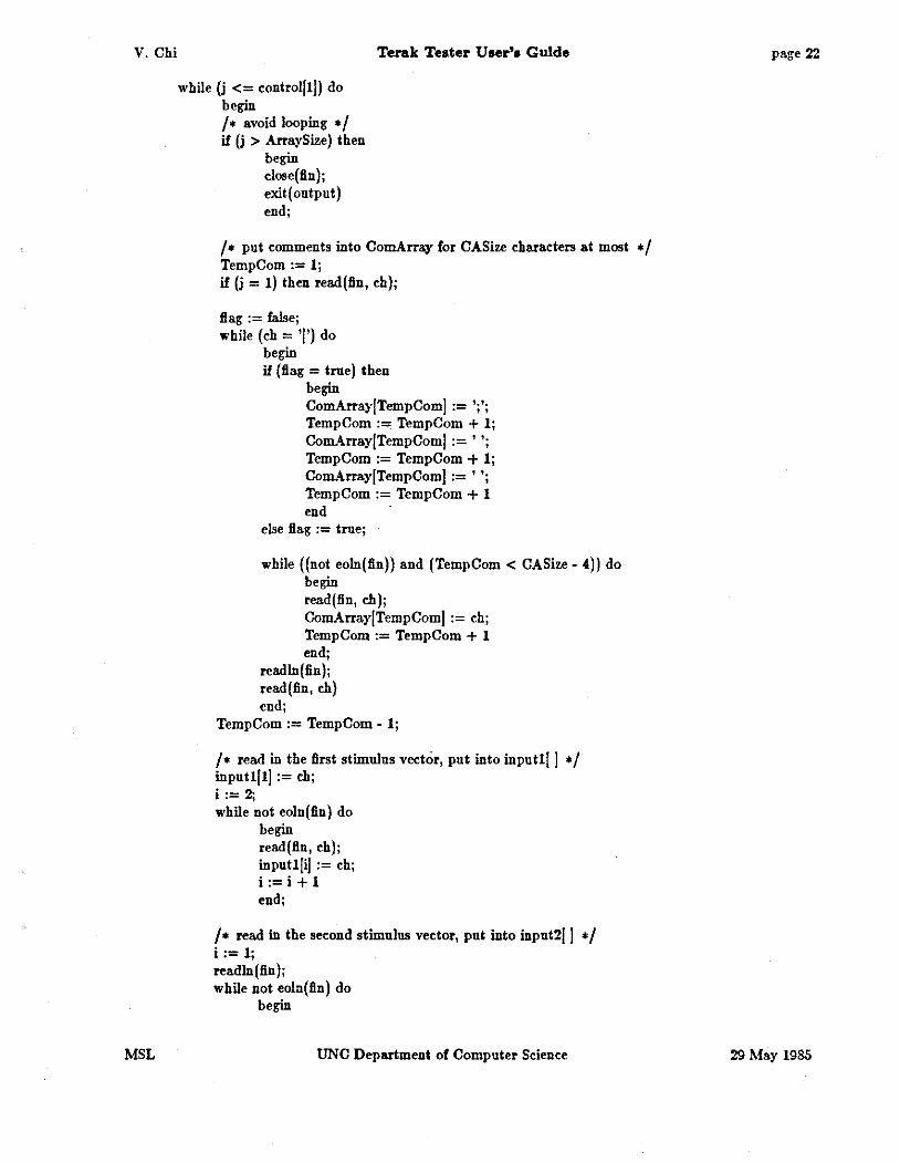
while (j <= control[!]) do begin I• avoid looping •I if (j > ArraySize) then
begin close( fin); exit( output) end;
I • put comments into ComArray for CASize characters at most • I TempCom := 1; if (j = 1) then read(fln, ch);
flag := false; while (ch = 'I'J do
begin if (Bag= true) then
begin ComArray[TempComl := ';'; TempCom := TempCom + 1; ComArray[TempCom[ := ' '; TempCom := TempCom + 1; ComArray[TempCom[ := ' '; TempCom := TempCom + 1 end ·
else Bag := true;
while ((not eoln(fln)) and (TempCom < CASize- 4)) do begin read(Bn, ch); ComArray[TempComl := ch; TempCom := TempCom + 1 end;
readln(fin); read(fin, ch) end;
TempCom := TempCom - 1;
I• read in the first stimulus vector, put into input
V. Chi
read(lln, ch); iuput2Ji] := ch; i := i +! end;
Terak Teater U oer'a G ulde
I• read iu the response vector, put into OutStr]] •I readln (fin); read( fin, ch ); GlobaiTOut:= ch; i := 1; repeat read(lln, ch);
OutStr]i] := ch; i := i + 1
until i > 8;
priutout(response, j);
readln(lln); read(lln, ch);
j:= j + 1; end; I• while •I
write(' processiug complete');
close( fin); close(fout, lock)
end; /• output •I
procedure init(var stimulus: StimArray; var response: RespArray); var i: integer;
begin
end;
for i := I to Arraysize do stimulus]i] := 0;
for i := 1 to HalfSize do response]i] := 0;
begin I• pxpl30test •I iuit( stimulus, response); getdata(control, stimulus);
exercise( control, stimulus, response, termed);
if (termed < > 0) then writeln('error iu Gceltest', control] I])
else output( response)
end. I • pxpl30test • I
MSL UNC Department of Computer Seience
page 23
29 May 1985

V. Chi Tel'llk Teater Uoel"1 Guide page 24
9 Appendix A: Annotated Gee! oyntax Words enclosed in ' ' are key words of the <kellanguage. Words enclosed in < > are nonterminal symbols in the Gee! grammer. Expressions enclosed in ( I are optional.
Grammer rules are written as "<nonterminal> : <alternative> I <alternative>;" just as in YACC. Notes indented under a rule are a description of the semantics of that rule.
<prog>
<stmts>
<stmt>
MSL
<stmts> A program is a series of statements.
<stml> <stmts> <simi>
'lo' <pins> ';' Set the pins in the list to 0. If all of the pins are in the same word, they will be set to 0 simultaneously. No other pius are aft"eeted.
'hi' <pins> ';' Set the pius in the list to 1. If all of the pins are in the same word, they will be set to 1 simultaneously. No other pins are aft"eeted.
'assert' (hold(('@' <number>( ';' Transfer words from the stimulus array position determined by the stimulus pointer to the pins. The number of words transferred is dependent on the number of pins declared in the stimulus declaration. The first word is transferred to a contiguously numbered sixteen pin group, starting with pin number 16• < number > + 1; the next word is transferred to the next sixteen pin group, i.e., starting with pin number 16 • ( < number > + 1) + 1, and so on. The default value for <number> here is zero. H the "hold" option is specified, the stimulus pointer is not incremented, otherwise it is incremented for each word transferred.
'read' (hold(('@' <number>( ';' Transfer words from the pins to the response array position determined by the response pointer. The number of words transferred is dependent on the number of pins declared in the response deelaration. The first word is transferred from a contiguously numbered sixteen pin group, starting with pin number 16• < number > + 1; the next word is transferred from the next sixteen pin group, i.e., starting with pin number 16 • (<number> +1) + 1, and so on. The default value for <number> here is zero. H the "hold" option is specified, the response pointer is not incremented, otherwise it is incremented for each word transferred.
'dock' <value> ';' Run the speeifled number of non-overlapping 2-phase dock cycles. The pins aft"eeted are those speeified in the
UNC Department of Computer Science 29 May 1985
V. Chi
<pins>
MSL
Terak Tester User'• Guide
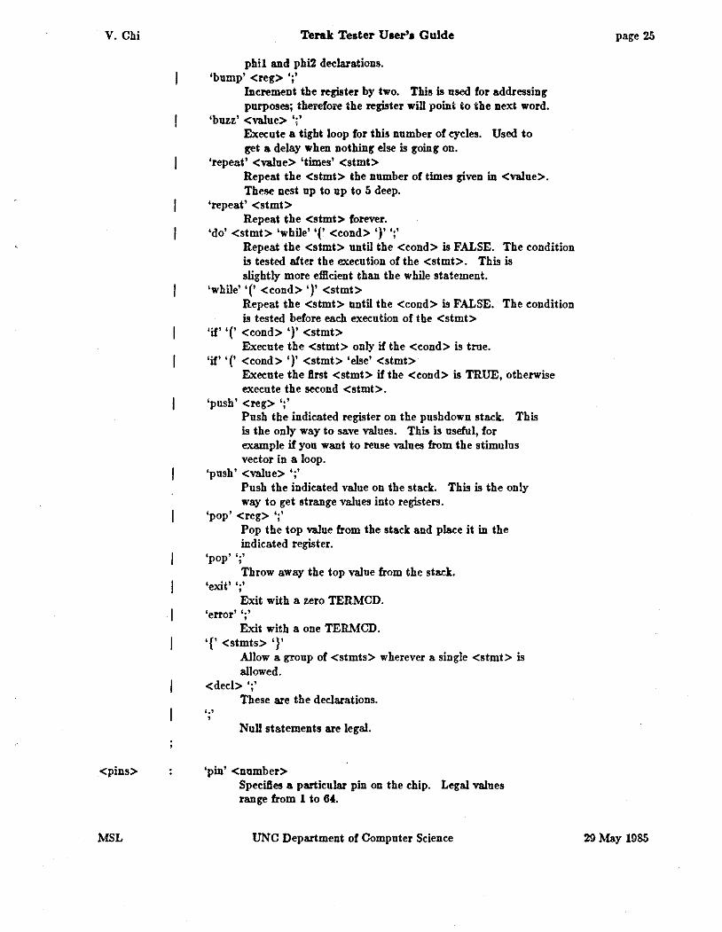
phil and phi2 declarations. 'bump' <reg> ';'
Increment the register by two. This is used for addressing purposes; therefore the register will point to the next word.
'buzz' <value> ';' Execute a tight loop for this number of cycles. Used to get a delay when nothing else is going on.
'repeat' <value> 'times' <stmi> Repeat the <stmt> the number of times given in <value>. These nest up to up to 5 deep.
'repeat' <stmt> Repeat the <simi> forever.
'do' <stmt> 'while''(' <cond> ')' ';' Repeat the <stmi> until the <cond> is FALSE. The condition is tested after the execution of the <simi>. This is slightly more efficient than the while statement.
'while' '(' <cond> ')' <stmt> Repeat the <stmt> until the <cond> is FALSE. The condition is tested before each execution of the <stmt>
'if''(' <cond> ')' <stmt> Execute the <stmi> only if the <cond> is true.
'if''(' <cond> ')' <stmt> 'else' <stmt> Execute the first <stmt> if the <cond> is TRUE, otherwise execute the second <stmt>.
'push' <reg> ';' Push the indicated register on the pushdown stack. This is the only way to save values. This is useful, for example if you want to reuse values from the stimulus vector in a loop.
'push' <value> ';' Push the indicated value on the stack. This is the only way to get strange values into registers.
'pop' <reg> ';' Pop the top value from the stack and place it in the indicated register.
'pop'';' Throw away the top value from the stack.
'exit' ';' Exit with a zero TERMCD.
'error' ';' Exit with a one TERMCD.
'{' <stmts> '}' Allow a group of <stmts> wherever a single <stmt> is allowed.
<ded> ';'
'·' '
These are the declarations.
Null statements are legal.
'pin' <number> Specifies a particular pin on the chip. Legal values range from 1 to 64.
UNC Department of Computer Science
page 25
29 Msy 1985
V. Chi
<cond>
<dec!>
<value>
<reg>
MSL
Terak Tester User'• Guide
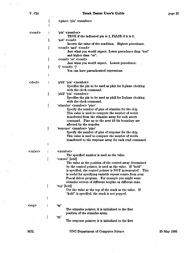
<pins> 'pin' <number>
'pin' <number> TRUE if the indicated pin is 1, FALSE if it is 0.
'not' <eond> Inverts the value of the eondition. Highest precedence.
<cond> 'and' <cond> Just what you would expect. Lower precedence than "not" and higher than "or".
<cond> 'or' <cond> Just what you would expect. Lowest precedence.
'(' <cond> ')' You tan have parenthesized expressions.
'phil' 'pin' <number> Specifies the pin to be used as phil for 2-phase clocking with the clock eommand.
'phi2' 'pin' <number> Speeifies tbe pin to be used as phi2 for 2-phase clocking with the clock eommand.
'stimulus' <number> 'pins' Specify the number of pins of stimulus for the chip. This value is used to compute the number of words transferred from the stimulus array for each assert command. Pins up to the next 16 bit boundary are affected by the transfer.
'response' <number> 'pins' Specify the number of pins of response for the chip. This value is used to compute the number of words transferred to the response array for each read command.
<number> The specified number is used as the value.
'control' JholdJ The value at the position of the control array determined by the control pointer, is used as the value. If "hold" is specified, the control pointer is NOT incremented. This is useful for specifying variable repeat counts from your Pascal driver program. For example you might want stimulus vectors of different lengths on different runs.
'top' JholdJ
'sp'
'rp'
Use the value at the top of the stack as the value. If "hold" is specified, the stack is not popped.
The stimulus pointer; it is initialized to the first position of the stimulus array.
The response pointer; it is initialized to the first
UNC Department of Computer Science
page 26
29 May 1985
V. Chi
<number>
<digit>
MSL
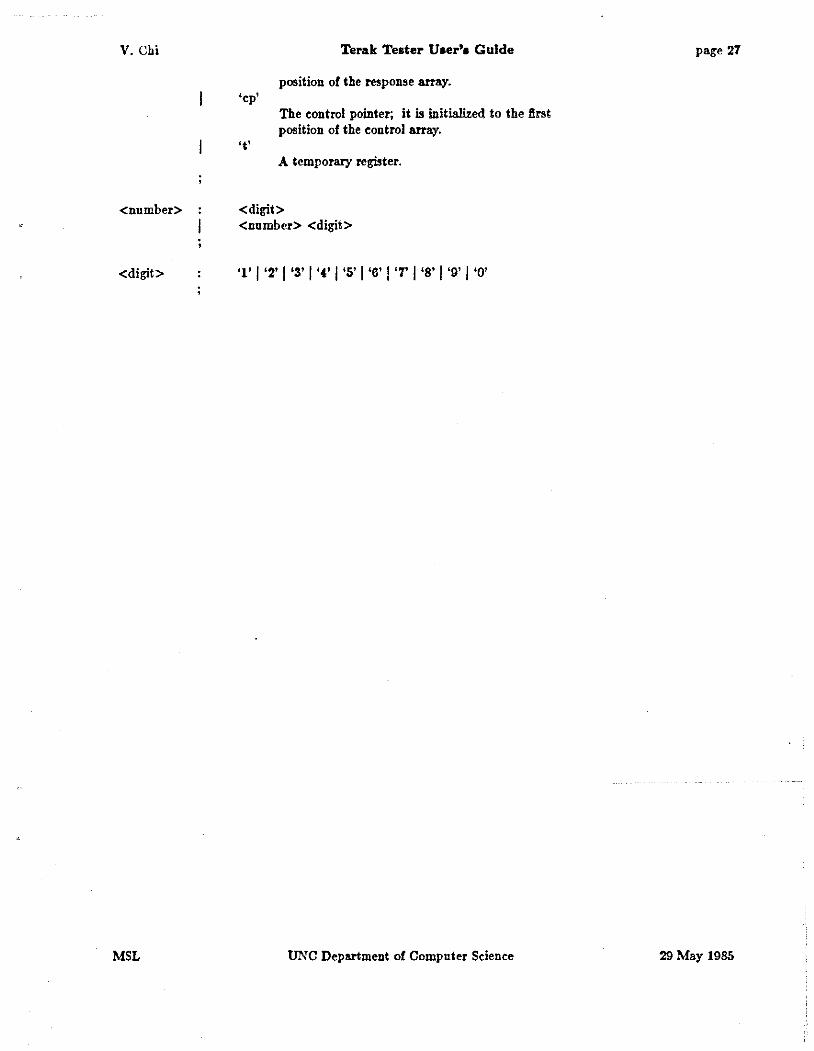
'cp'
't'
Terak Tester Uaer'a Guide
position of the response array.
The control pointer; it is initialized to the first position of the control array.
A temporary register.
<digit> <number> <digit>
UNC Department of Computer Science
page 27
29 May 1985
V. Chi Terak Teater U~er'• Guide page28
10 Appendix 81 NltQ-·crltt7 det.U. ud cookbook proeedurea
There are numerous procedural details to deal with iD order to el'edively use the Terak Tester to test your chips. These iaclude settiDI' up ,our UNIX aad UCSD environments, aad communication between them. This appendix provides cookbook procedures aad step-by-step examples to help overcome the leamiDI' effort for the lrst time user.
Ia examples throupout this appendix, the followiDI' font conventions are used: • UNIX prompts are shown iD a tnnruer font.
• UCSD Paseal prompts are shown iD a Sans Serif font.
• User respoDSeS are shown iDa Sluted Romaa font.
• The symbol~"' indicates a user-entered -return"' character.
• Comments are enclosed iD '''/• • /"' delimiters.
• A character preceded by a "t"' indicates "control"' character.
10.1 The UNIX environment
Documents are commercially available for ,our reference (5, 6). It is presumed JOU are suftleieatly coaversaat with UNIX to be able to use the commaad sheD, au editor, and other basic UNIX utilities. Instruction on UNIX, beiDI' beyond the scope of this document, is best obtained from ,our local UNIX hackers, if you need it.
As a Terak Tester user, ,ou should login to UNIX as "terak"', uDless JOU have ,our own login. A password is available from MSL personnel. When you Irs& login, create a sub-directory with a name of your cboiee; subsequently, always work within this sqb-direetory. There is no mechanism to keep users from walkiag on each other's lies other than common courtesy and sood sense. By workiDI' only within your own directory, you are proteetinl' other users from your mistakes, as weU as providinl' ,ourself a barrier against theirs. Thla wUI onl)o work If evel')' UHr obeervea thla protoeol. Do it. It's for your own protection.
10.2 The UCSD/Terak environment
General documentation regardiDI' the UCSD Pascal system (3) and the Terak implementation (4) are available. These should be referenced, as necessary while usiDI' the Terak. This section is intended to speed you through some of the el'ort common to aU users of the Terak Tester.
Every user should have at least one "working" disk, and should refl'aln ftom ualns anyone elae'•· The following procedure will conlgure a disk wbieh is ready for JOU to use in your testing efforts.
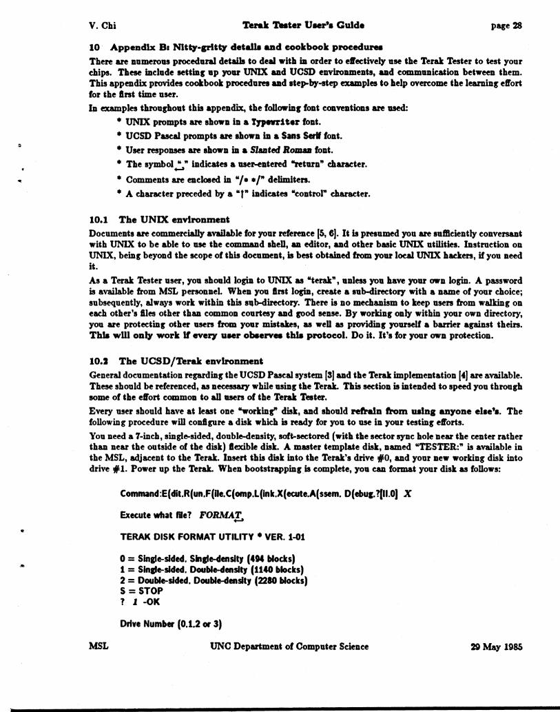
You need a 7-inc:h, single-sided, double-density, soft-sectored (with the sector sync: bole near the center rather than near the outside of the disk) lexible disk. A master template disk, named "TESTER:" is available in the MSL, adjacent to the Terak. lasert this disk into the Terak's drive :fi:O, and your new working disk into drive :fl:l. Power up the Terak. When bootstrappinl' is complete, you eaa format your disk as follows:
MSL
Command:E(dit.R(un.F(Ue.C(omp.L(ink.X(ecute.A(ssem. D(ebuc.?(II.O) X
Execute what file? FORMAL
TERAK DISK FORMAT UTILITY • VER. 1-01
0 = Single-sided. Single-density (4M blocks) 1 = Single-sided. Double-densltJ (1140 blocks) 2 = Double-sided. Double-density (2210 blocks) S =STOP 1 l -OK
Drive Number (0.1.2 or 3)
UNC Department of Computer Science 29 May 1985

V. Chi Terak Tester User's Guide
1 l -OK
PLACE DISK IN DRIVE 1 - TYPE ANY KEY WHEN READ't,
Cylinder (x10): 01234567 FORMAT COMPLETE- NO ERRORS DETECTED
0 = Single-sided. Single-density (404 blocks) 1 = Single-sided. Double-density (1140 blocks) 2 = Double-sided. Double-density (2280 blocks) S =STOP 1 S I• The "S" most be explieitly upper ease here. •I
?REEBOOT ADVISED? I• Do reboot the system. •I
page 29
You will also need a basic set of supporting files on your disk. These are exactly the same as those on the "TESTER:" disk. In order to get them on your disk, do a "volume to volume transfer". Assuming you have just formated your disk and rebooted the system, the procedure is as follows:
Command:E(dit.R(un.F(ile.C(omp.L(ink.X(ecute.A(ssem. D(ebug. ?(11.0) F Filer: G(et. S(ave. W(hat. N(ew. L(dir. R(em. C(hng. T(rans. D(ate. Q(uit (C.4) T Transfer what file ? TESTER~
To where? #~
Transfer 1140 blocks ? (YIN) Y TESTER: -> #5: I• This is actually below the prompt line on the Terak screen. •I Filer: G(et. S(ave. W(hat. N(ew. L(dir. R(em. C(hng. T(rans. D(ate. Q(uit [C.4)
I• Remove the "TESTER:" disk from Drive #0 and re-file it. Move your working disk •I I• from drive #1 to drive #0 and reboot the system. •I Command:E(dit.R(un.F(ile.C(omp.L(ink.X(ecute.A(ssem. D(ebug.?(II.O) F Filer: G(et. S(ave. W(hat. N(ew. L(dir. R(em. C(hng. T(rans. D(ate. Q(uit [C.4) C Change what file ? TESTEJ!:, Change to what ? NAME~ I• Name of your choice; ":" is required. •I TESTER: -> NAME: I• This is actually below the prompt line on the Terak screen. •I Filer: G(et. S(ave. W(hat. N(ew. L(dir. R(em. C(hng. T(rans. D(ate. Q(uit [C.4) Q
If aU goes according to this scenario, your disk is now ready to use. The UCSD system is relatively friendly, and if things don't go exactly as shown, error recovery is generally pretty straightforward. In a pinch, refer to the documents eited above.
10.3 Host to Terak eommunleatlons
Communications between the UNIX Host and the Terak is via a 4800 blsee serial link. Connect the Terak's RS-232 port (a DB-25 connector) to a suitable terminal port which can access the UNIX Host. This port may or may not be routed through the UNCCC PACX (the Gandalf switch).
The "TERMINAL" program on your working disk supports interactive (terminal) communications, as well as file transfers between the UCSD Pascal and UNIX file systems. Assuming you have booted the Terak on your working disk, connected the terminal line, and switched on the connection switch (if any):
Command:E(dit.R(un.F(ile.C(omp.L(ink.X(ecute.A(ssem. D(ebug. ?(11.0) X
MSL UNC Department of Computer Seienee 29 May 1985

V. Chi Terak Tetoter User's Guide
Execute what me? TERMINAf_
TERMINAl V02-01 .. terminal emulator and file transfer utility. type DC2 to alpha ease toggle. f EOM to command. f NUL to break.
I• If Host tonneetion is <lireet, ignore these commented steps. •I I• PACX prompts are in normal Roman font, comments are in "( )". •I I• ....., (repeat until you get the PACX's attention) •I I• enter service ~ (this may not l!"et echoed) •I I• (au optional PACX "message of the day" may appear) •I I• class 021 start (if "busy" or "unavailable", try again later) •I
page 30
UIIC Microelectronic Syateu Laboratory Vax/4.2 BSD (joha) I• Depends on which UNIX Host, of course. •I
logill: tera.!,
Password: <password?:, I• Your password is not echoed. •I
I• UNIX "message of the day" and other environment-dependent stuff will appear. •I
I I• This is the default UNIX shell prompt. •I
The Terak and the UNIX Host are now connected and communicating. Yon can now interactively get into your working UNIX directory:
1 cd <directory?:, I
Once you are in your working UNIX directory, you are ready to transfer Illes between the Tester and the UNIX Host. The steps are as follows:
t EOM I• i.e., simultaneously press "ctrl" and "EO!\{" keys •I Terminal: S(end file. R(eceive me. T(erminal mode. Q(uit S
I• Send a file from your local Tester disk to your UNIX directory •I Send file: Text only so .TEXT automatically appended to TERAK filenames File name on this TERAK (ending .TEXT assumed): <teraktlle?:, Enter Unix filename: < unix/1/e;::_, Transmitting ... I• This may only briefly flash on the screen for short Illes. •I Terminal: S(end file. R(eceive file. T(ermlnal mode. Q(uit R
I• Transfer a file from your UNIX directory to your local Terak disk. •/ Enter Unix filename: <unixflle?:,
File name on this TERAK (ending .TEXT assumed): <teraktlle?:, Receiving ...
<unlx.file> transferred to <terak.file>.TEXT Terminal: S(end file. R(eceive file. T(ermlnal mode. Q(ult /• Do whatever comes next. •/
10.4 Complllng your Gee) program
MSL UNC Department of Computer Science 29 May 1985

V. Chi Terak Teater User'• Guide page 31
Assuming yon have written your Geel program and it is stored in "exercise.g" in your current working directory on the UNIX Host, the procedure for compiling it is straightforward.
I• Yon must be logged into UNIX and in your working directory •I 1 fusrfcat/bin/geel exercise;~. 1
U there are no syntax errors in your Gcel source code, Geel should exit normally and leave the object file, "exercise.t" in your current working directory.
This object file must be transferred to the Terak for subsequent assembly and inclusion in the ftnal test program. The Terak system will expect a ".TEXT" sufllx to whatever ftle name you use for this file on your UCSD Pascal working disk. This suffix is automatically appended by the "TERMINAL" utility, as described above.
10.5 Assembling your Gee! program
Assuming you have a compiled Geel ftle, "EXERCISE. TEXT" on your working disk. You can assemble this to LSI-11 machine code, as follows:
I• The Terak must be booted with your working disk mounted. •I Command:E(dit.R(un.F(ile.C(omp.L(ink.X(ecute.A(ssem. D(ebug. ?(11.0) A Assembling ... Assemble what text? EXERCI% To what codefile? EXERCI% I• Ml!f be another name. •I 11 Assembler II.O(d.4) Output file for assembled &sting: (<CR> for noneL
I• A bit map of the core image is displayed during assembly. •I
I• Source code dependent messages here. •I
Assembly complete: X lines I• X depends on your source code. •I 0 Errors flagged on this Assembly I•. Hopefully, at least. •I
Command:E(dit,R(un.F(ile.C(omp.L(ink.X(ecute.A(ssem. D(ebug,?(II.OJ I• At top of screen. •I
If assembly is successful, the file "EXERCISE. CODE" will be left on your working disk. If there are errors Bagged, or the assembler otherwise balks, the UCSD Pascal Reference Manual [3] should be consulted (see the last section of this guide).
10.6 CompUing your Driver program
Your Pascal driver program may be entered directly on the Terak, or may be edited and syntax checked by using the UNIX compiler on the UNIX Host. In the latter case, the Pascal source file must be transferred to the Terak for compilation to UCSD p-code. Assuming the driver source code is on your Terak working disk in the file "DRIVER. TEXT", the procedure for compiling it is:
MSL
I• The Terak must be booted with your working disk mounted. •I Command:E( dit.R(un.F(IIe.C(omp.L(Ink.X( ecute,A( ssem, D(ebug. ?(11.0) C
UNC Department of Computer Science 29 May 1985
V. Chi Terak Teater User'• Guide page 32
Compiling ... Compile what text? DRIVE!!., To what codefile? DRIVE!!., I• May be another name. •I
I• A bit map of the core image is displayed during compilation. •I
PASCAL Compiler (II.O.A.l)
/• Sour<:e code dependent messages •/
Command:E(dit.R(un.F(Re.C(omp.L(ink.X(ecute.A(ssem. D(ebug.?[II.O]/• At top ofscreen. •/
If compilation is successful, the ftle "DRIVER.CODE" will be left on your working disk. If your code won't compile, the UCSD Pascal Reference Manual (3[ should be consulted (see the last section of this guide).
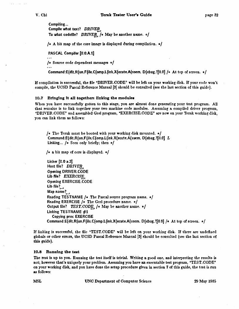
10.7 Bringing It all together: linking the module•
When you have successfully gotten to this stage, you a.re almost done generating your test program. All that remains is to link together your two machine eode modules. Assuming a compiled driver program, "DRIVER. CODE" and assembled Geel program, "EXERCISE. CODE" are now on your Terak working disk, yon ean link them as follows:
I• The Terak must be booted with your working disk mounted. •I Command :E( dit.R(un.F (ile. C(omp.L(ink.X(ecu!e.A( ssem. D(ebug. ?[11.0) L Linking ... /• Seen only briefly; then •/
I• a bit map of core is displayed. •/
Linker (11.0 a.2J Host file? DRIVE!!., Opening DRIVER. CODE Lib file? EXERCIS§, Opening EXERCISE. CODE Lib file?._, Map name?._,
Reading TESTNAME /• The Pa.seal sonr<:e program name. •I Reading EXERCISE I• The Gcel procedure name. •I Output file? TEST.COD!f./• May be another name. •/ Linking TESTNAME #1
Copying proc EXERCISE Command:E(dit.R(un.F(ile.C(omp.L(ink.X(ecute.A(ssem. D(ebug. ?(11.0) I• At top of screen. •/
If linking is successful, the file "TEST.CODE" will be left on your working disk. If there are undefined globals or other errors, the UCSD Pascal Reference Manual (3] should be consulted (see the last section of this guide).
10.8 Running the teat
The rest is up to you. Running the test itself is trivial. Writing a good one, and interpreting the results is not; however that's uniquely your problem. Assuming you have an executable test program, "TEST. CODE" on your working disk, and you have done the setup procedure given in section 7 of this guide, the test is run as follows:
MSL UNC Department of Computer Science 29 May 1985

V. Chi Terak T .... ter User'• Guide page 33
f• The Terak must be booted with your working disk mounted. •/ Command :E( dit.R(un.F(ile.C(omp.L(ink.X(ecute.A(ssem. D(ehug. ?(II. OJ X Execute what file? TES!,
I• Whatever happens now is what yon programmed. •I
I• Upon exit, (normal or abnormal) you will get baek the UCSD prompt: •I Command:E(dit.R(un.F(ile.C(omp.L(ink.X(ecute.A(ssem. D(ebug.?(II.O) /• At top of screen. •I
Thai's all, folks. If you've gotten this far, you are suftloiently well versed in the mechanics of using Gee! and the Terak Tester to do your tests. Don't be discouraged if your tests need a lot of debugging, not to mention your chip design. Such is a normal state of affairs, even for the experienced. Good ludd
11 Referenees
MSL
jiJ Kathleen Jensen and Nildaus Wirth, "PASCAL User Manual and Report", Second Edition, Springer-Verlag, New York, 1975.
121 Wilson, I. R., and Addyman, A.M., "A Practical Introduction to Pascal", Springer-Verlag, New York, 1978.
ISJ "UCSD Pascal Users Manual", Ed. by Shillington, K. A., Ackland, G. M., and Clark, R., Softeeh Microsystems, San Diego, 1980.
I4J "TERAK/UCSD p-SYSTEM VERSION II.O OPERATING SYSTEM", document number 60-0111-00IA, Terak Corporation, Scottsdale, AZ, 1982.
I5J "UNIX Programmer's Manual", Seventh Edition, Virtual VAX-11 Version, UCB, Berkeley, CA, 1981.
J6J Brian W. Kernighan and Dennis M. Ritchie, "The C Programming
I7J Gary Bishop, "Self Tracker: A Smart Optical Sensor on Silicon", PhD Thesis, Chapel Hill, NC, 1984.
UNC Department of Computer Science 29 May 1985