the time is right - garland group
TRANSCRIPT

InstallationInstructions
TM
Roast Beef CookingController UpgradeModel IR081C1H760X & IR081C1H765X
THE UNAUTHORIZED USE OR DUPLICATION OF THE SOFTWARE DE-SCRIBED HEREIN, OR THIS MATERIAL, IS STRICTLY PROHIBITED.
All Products CE Approved
The
Tim
e Is
Rig
ht
229-51014 Rev. E© 1996-2001 Food Automation - Service Techniques, Inc.
Toll-Free Technical Support24 Hours A Day, 365 Days A Year(from the U.S., Canada and the Caribbean)
1-800-243-9271
2 THE UNAUTHORIZED USE OR DUPLICATION OF THE SOFTWARE DESCRIBED HEREIN,OR THIS MATERIAL, IS STRICTLY PROHIBITED.
INDEX
INTRODUCTIONThank you for your purchase. In choosing FAST you have chosen a product with over 25 years ofinnovation and quality manufacturing behind it. The (FASTRON.)® Silver EditionTM CookingController is designed to simplify your cooking process and allow your foodservice operators tospend more time with the customers and other important responsibilities. Quality control of yourfood product is assured through the various features, notification displays and alarms designed intothe Controller.
There are three modes of operation on the (FASTRON.)® Silver EditionTM Cooking Controller:
Operating Mode: used to cook various menu itemsProduct Programming Mode: used to add or modify menu items/parameterSystem Programming Mode: used to configure the controller to various applications
This instruction booklet covers the installation of the cooking controller system. For operating andprogramming instructions, please refer to the FAST manual part number 229-51012.
BEFORE YOU START ............................................. 3
CONTROLLER OPERATING ENVIRONMENT ............ 4
CUSTOMER SERVICE AND TECHNICALASSISTANCE ................................................ 17
INSTALLATION: CONTROLLER, MANIFOLDAND HEAT RELAY ......................................7-16
INTRODUCTION ................................................... 2
MOUNTING FIGURES..................................... 11, 13
OPERATION ................................................... 14
PARTS KIT, REQUIRED TOOLS AND CONTROLLEROPERATING ENVIRONMENT ........................... 4
PART NUMBER LISTING ........................................ 5
PARTS REQUIRED ON ALL INSTALLATIONS ........... 6
PATENTS ........................................................... 17
TOOLS REQUIRED ................................................ 4
WARRANTY STATEMENT.................................... 17
WIRING DIAGRAM ........................................... 15
FAST is not liable for any use of product not in accordance with FAST’sinstallation and operating instructions.
Before using this equipment, or for any questions on the operation of theappliance, consult and follow all instructions and safety warnings found inthe appliance operator’s manual supplied from the manufacturer of theappliance.
THE UNAUTHORIZED USE OR DUPLICATION OF THE SOFTWARE DESCRIBED HEREIN,OR THIS MATERIAL, IS STRICTLY PROHIBITED.
Literature Part #229-51014 Rev. D
3
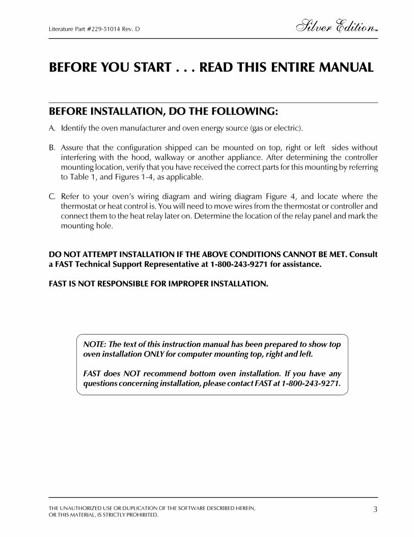
NOTE: The text of this instruction manual has been prepared to show topoven installation ONLY for computer mounting top, right and left.
FAST does NOT recommend bottom oven installation. If you have anyquestions concerning installation, please contact FAST at 1-800-243-9271.
BEFORE YOU START . . . READ THIS ENTIRE MANUAL
BEFORE INSTALLATION, DO THE FOLLOWING:A. Identify the oven manufacturer and oven energy source (gas or electric).
B. Assure that the configuration shipped can be mounted on top, right or left sides withoutinterfering with the hood, walkway or another appliance. After determining the controllermounting location, verify that you have received the correct parts for this mounting by referringto Table 1, and Figures 1-4, as applicable.
C. Refer to your oven�s wiring diagram and wiring diagram Figure 4, and locate where thethermostat or heat control is. You will need to move wires from the thermostat or controller andconnect them to the heat relay later on. Determine the location of the relay panel and mark themounting hole.
DO NOT ATTEMPT INSTALLATION IF THE ABOVE CONDITIONS CANNOT BE MET. Consulta FAST Technical Support Representative at 1-800-243-9271 for assistance.
FAST IS NOT RESPONSIBLE FOR IMPROPER INSTALLATION.

4 THE UNAUTHORIZED USE OR DUPLICATION OF THE SOFTWARE DESCRIBED HEREIN,OR THIS MATERIAL, IS STRICTLY PROHIBITED.
BEFORE YOU START . . .
Parts KitPlease inspect the package carefully, ensuring that there is no damage to the carton. Once opened,carefully unpack the material, making sure that all of the parts described on the following pages arepresent. Note there are several small parts included with the computer, manifold, relay assemblyand cables. If any of the parts listed are missing, please call the FAST Technical Service Departmentat 1-800-243-9271, 8-5 PM EST.
Also included should be: Operating Manual 229-51012
Tools Required
� Power drill, with drill bits (1/16� through 1/2�) and a #29 drill (.131 dia.)� Screwdrivers, Phillips and Slotted� High Temperature Sealant (GE RTV 106, or equivalent)� Wire Fish Device� Crimping Tool� Adjustable Wrench� Safety Glasses� 7/8� diameter Knockout Punch or Stepper Drill
Controller Operating EnvironmentPLEASE NOTE: The solid state components in this controller are designed to operate reliably in atemperature range up to 158°F / 70°C. Before installing this controller, it should be verified that theambient temperature at the mounting location does not exceed 158°F / 70°C.

THE UNAUTHORIZED USE OR DUPLICATION OF THE SOFTWARE DESCRIBED HEREIN,OR THIS MATERIAL, IS STRICTLY PROHIBITED.
Literature Part #229-51014 Rev. D
5
PART NUMBER LISTING
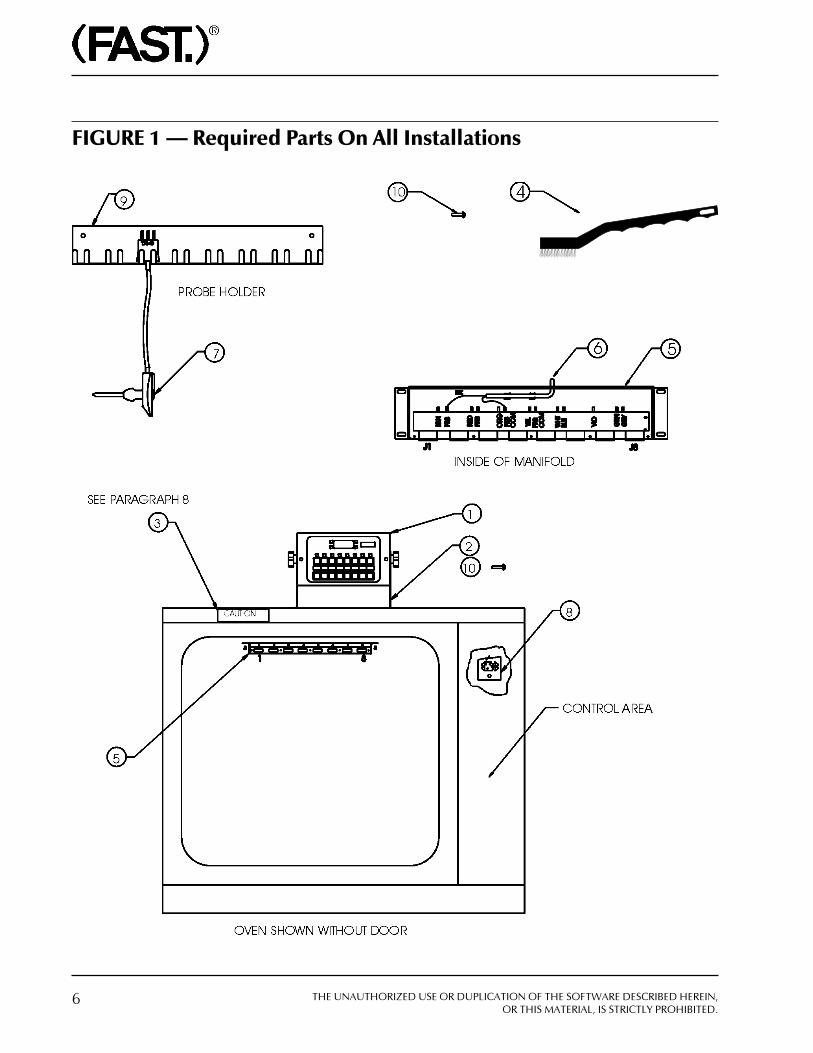
Table IDefines parts that are required on all installations (see figure 1).
X = assembly provided with #8 x 1/2 self-tap mounting screws.
METI METI METI METI METI .ONTRAP .ONTRAP .ONTRAP .ONTRAP .ONTRAP .YTQ .YTQ .YTQ .YTQ .YTQ NOITPIRCSED NOITPIRCSED NOITPIRCSED NOITPIRCSED NOITPIRCSED STNEMMOC STNEMMOC STNEMMOC STNEMMOC STNEMMOC
1roX067H1C180RI
X567H1C180RI1 RELLORTNOCTSAF
2 34525–412 2RELLORTNOCTEKCARB
GNITNUOM
3 58501–461 1 LEBALNOITUAC
4 82005–091 1 HSURB
5 10–73605–312 1 YSSADLOFINAM X
6 40–70106–041 1 EBORPNEVO
7 50–21106–041 8 EBORPTAEM
8 20–91605–312 1 YSSAYALER X
9 26825–412 1 REDLOHEBORPTAEMTEKCARB
01 41001–051 9 .S.SPATFLESDHNAP"2/1X8#
11 31-01205-222 1OTRELLORTNOCSSENRAH
GNITNUOMPOTDLOFINAMX
21 30-81205-222 1YALEROTRELLORTNOCSSENRAH
GNITNUOMPOTYSSA
31 00925-412 1 TROPPUSRELLORTNOCTEKCARB
41 10-60705-312 1 GULPTSET
51 05327-081 4,DAEHNAP"2/1x23-8#RCS
LEETSSSELNIATS
6 THE UNAUTHORIZED USE OR DUPLICATION OF THE SOFTWARE DESCRIBED HEREIN,OR THIS MATERIAL, IS STRICTLY PROHIBITED.
FIGURE 1 � Required Parts On All Installations

THE UNAUTHORIZED USE OR DUPLICATION OF THE SOFTWARE DESCRIBED HEREIN,OR THIS MATERIAL, IS STRICTLY PROHIBITED.
Literature Part #229-51014 Rev. D
7
INSTALLATION
Controller / Manifold InstallationSURVEY:1. Make sure that the oven is empty and cool enough to work in. Note that the oven figures shown
are typical of ovens you will be working with, but they may not match every detail of every ovencurrently in use. As the installer, you must pay careful attention to these minor differences. Toassure that the system you have received will fit the oven you are retrofitting (cable lengths,access and overall requirements) do the following:
Remove panel to control area and determine heat control wiring so that a location for the relayassembly can be selected. Mark the relay assembly location. Tentatively position controller,take the heat control relay cable (P/N 222-50218-03) from computer to control area anddetermine the location of the 7\8� dia. hole �B� which will mount the cable clamp to oven skinand allow you to make connections to the relay assembly. Mark cable clamp hole location andtentatively position the relay assembly. Take the heat relay cable and assure that it will reachthe relay assembly location previously selected and connections can be made to the computer.Having done this and there are no problems proceed to the detail installation.
OVEN PROBE INSTALLATION:2. Insert probe in hole provided in the rear of the manifold housing, rotate the probe and snap into
clips. If probe is loose in the clips, gently pinch clip ears with pliers to secure. Then makeconnections to probe and probe common as shown in figure A below; probe wires areinterchangeable.
Figure ACABLE MOUNTING:
WARNING: Before starting, ensure that power to the appliance andcontroller are shut OFF. Also, please read this entire manual prior tostarting the installation. Review the drawings at the end of the manualto become familiar with the components.
8 THE UNAUTHORIZED USE OR DUPLICATION OF THE SOFTWARE DESCRIBED HEREIN,OR THIS MATERIAL, IS STRICTLY PROHIBITED.
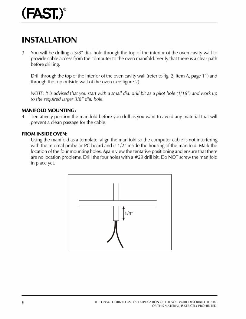
INSTALLATION3. You will be drilling a 3/8� dia. hole through the top of the interior of the oven cavity wall to
provide cable access from the computer to the oven manifold. Verify that there is a clear pathbefore drilling.
Drill through the top of the interior of the oven cavity wall (refer to fig. 2, item A, page 11) andthrough the top outside wall of the oven (see figure 2).
NOTE: It is advised that you start with a small dia. drill bit as a pilot hole (1/16�) and work upto the required larger 3/8� dia. hole.
MANIFOLD MOUNTING:4. Tentatively position the manifold before you drill as you want to avoid any material that will
prevent a clean passage for the cable.
FROM INSIDE OVEN:Using the manifold as a template, align the manifold so the computer cable is not interferingwith the internal probe or PC board and is 1/2� inside the housing of the manifold. Mark thelocation of the four mounting holes. Again view the tentative positioning and ensure that thereare no location problems. Drill the four holes with a #29 drill bit. Do NOT screw the manifoldin place yet.

THE UNAUTHORIZED USE OR DUPLICATION OF THE SOFTWARE DESCRIBED HEREIN,OR THIS MATERIAL, IS STRICTLY PROHIBITED.
Literature Part #229-51014 Rev. D
9
SECURE PROBE CABLE:5a. Top mount two external cable (see figure 2). Feed the controller cable through the 3/8� dia.
hole. Using the cable mounting flange as a template, drill two holes using a #29 drill bit. Securethe cable with supplied screws. 1/4� of conduit should clear the hole on the inside of the oven.If this is not the case, loosen the screw on the cable bulkhead fitting and adjust its length.
CONNECTING WIRES TO THE MANIFOLD:5b. Strip each of the wires 3/4� from the end, double wires over then crimp one uninsulated female
Faston to each of the wires. Connect wires to manifold board matching colors marked on theboard. Connect one black wire to �PRB� and the other Black wire to �PRB COM.� (See FigureA on page 7 or Figure 4 on page 15).
SECURING MANIFOLD:5c. After connecting the Fastons, screw the manifold into position, making sure to enclose all of the
wires inside the manifold. Note that the gap between the manifold and the ceiling of the ovenmust not exceed 1/32�. If the gap is larger than 1/32�, you must use GE RTV 106 to seal the gap.
NOTE: Do NOT pinch any of the wires between the manifold and the oven.
10 THE UNAUTHORIZED USE OR DUPLICATION OF THE SOFTWARE DESCRIBED HEREIN,OR THIS MATERIAL, IS STRICTLY PROHIBITED.
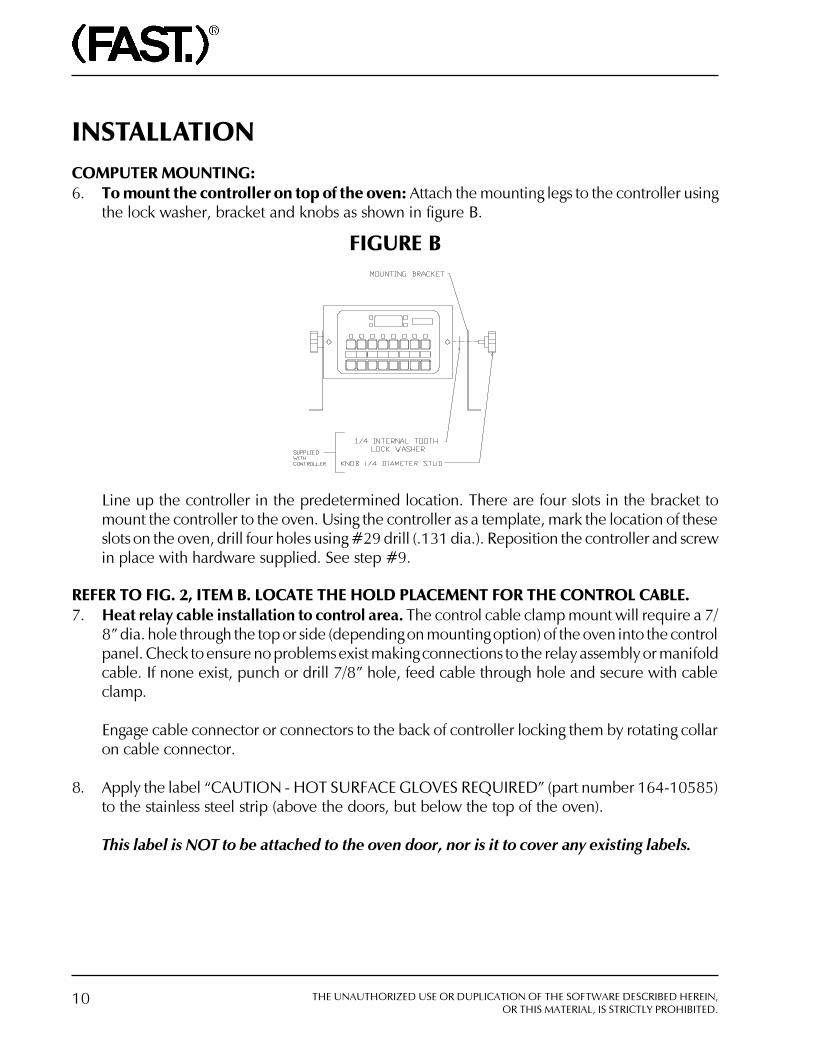
INSTALLATIONCOMPUTER MOUNTING:6. To mount the controller on top of the oven: Attach the mounting legs to the controller using
the lock washer, bracket and knobs as shown in figure B.
FIGURE B
Line up the controller in the predetermined location. There are four slots in the bracket tomount the controller to the oven. Using the controller as a template, mark the location of theseslots on the oven, drill four holes using #29 drill (.131 dia.). Reposition the controller and screwin place with hardware supplied. See step #9.
REFER TO FIG. 2, ITEM B. LOCATE THE HOLD PLACEMENT FOR THE CONTROL CABLE.7. Heat relay cable installation to control area. The control cable clamp mount will require a 7/
8� dia. hole through the top or side (depending on mounting option) of the oven into the controlpanel. Check to ensure no problems exist making connections to the relay assembly or manifoldcable. If none exist, punch or drill 7/8� hole, feed cable through hole and secure with cableclamp.
Engage cable connector or connectors to the back of controller locking them by rotating collaron cable connector.
8. Apply the label �CAUTION - HOT SURFACE GLOVES REQUIRED� (part number 164-10585)to the stainless steel strip (above the doors, but below the top of the oven).
This label is NOT to be attached to the oven door, nor is it to cover any existing labels.

THE UNAUTHORIZED USE OR DUPLICATION OF THE SOFTWARE DESCRIBED HEREIN,OR THIS MATERIAL, IS STRICTLY PROHIBITED.
Literature Part #229-51014 Rev. D
11
FIGURE 2
Top Mounting, Two External Cables
12 THE UNAUTHORIZED USE OR DUPLICATION OF THE SOFTWARE DESCRIBED HEREIN,OR THIS MATERIAL, IS STRICTLY PROHIBITED.
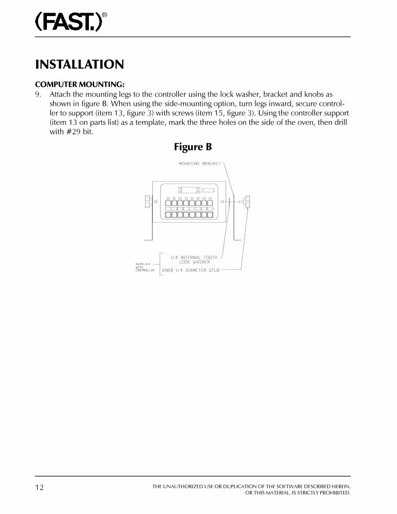
COMPUTER MOUNTING:9. Attach the mounting legs to the controller using the lock washer, bracket and knobs as
shown in figure B. When using the side-mounting option, turn legs inward, secure control-ler to support (item 13, figure 3) with screws (item 15, figure 3). Using the controller support(item 13 on parts list) as a template, mark the three holes on the side of the oven, then drillwith #29 bit.
Figure B
INSTALLATION
THE UNAUTHORIZED USE OR DUPLICATION OF THE SOFTWARE DESCRIBED HEREIN,OR THIS MATERIAL, IS STRICTLY PROHIBITED.
Literature Part #229-51014 Rev. D
13
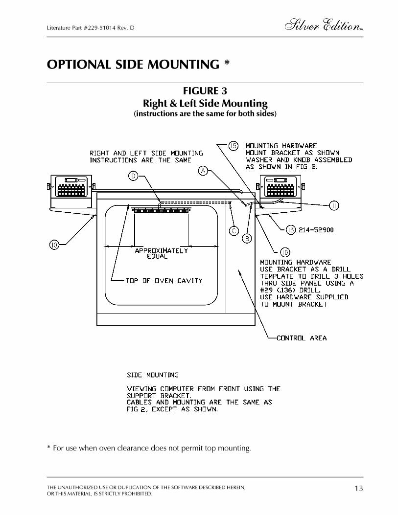
FIGURE 3Right & Left Side Mounting
(instructions are the same for both sides)
OPTIONAL SIDE MOUNTING *
* For use when oven clearance does not permit top mounting.

14 THE UNAUTHORIZED USE OR DUPLICATION OF THE SOFTWARE DESCRIBED HEREIN,OR THIS MATERIAL, IS STRICTLY PROHIBITED.
Heat Relay Installation10. Relay panel location previously selected in the control area. Use the relay panel as a template
to mark the mounting hole. Drill hole using #29 drill bit. Mount panel using screws supplied.
Make connections from the computer cable to the relay panel matching colors WHT/VIO andWHT/RED. See wiring diagram Figure 4. Tape any unused wires separately.
Disconnect the terminals from the manual thermostat and connect them to the relay panelwires YEL and BLU. Note there is no concern with matching colors to the thermostat. If the ovenyou are working on has a control other than a mechanical thermostat, call a FAST technicianbefore proceeding.
Probe Brackets Installation11. The meat probe holder is provided to prevent damage to the probes when not is use. Consult
with store manager for mounting location that best suits his needs. Mounting screws providedas shown in figure 1.
OPERATION1. Turn the power to the oven and controller back ON (controller must be plugged in).
2. Fan should turn on and heat should be on when the heat light on the beef controller is on. Ifnot, turn off and check heat relay connections.
3. Refer to the operating instructions for further information.
INSTALLATION

THE UNAUTHORIZED USE OR DUPLICATION OF THE SOFTWARE DESCRIBED HEREIN,OR THIS MATERIAL, IS STRICTLY PROHIBITED.
Literature Part #229-51014 Rev. D
15
FIGURE 4

16 THE UNAUTHORIZED USE OR DUPLICATION OF THE SOFTWARE DESCRIBED HEREIN,OR THIS MATERIAL, IS STRICTLY PROHIBITED.
NOTES
THE UNAUTHORIZED USE OR DUPLICATION OF THE SOFTWARE DESCRIBED HEREIN,OR THIS MATERIAL, IS STRICTLY PROHIBITED.
Literature Part #229-51014 Rev. D
17
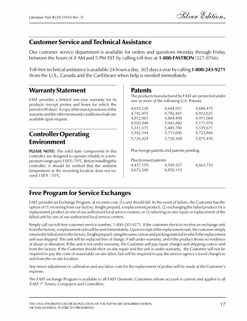
Customer Service and Technical AssistanceOur customer service department is available for orders and questions Monday through Fridaybetween the hours of 8 AM and 5 PM EST by calling toll-free at 1-800-FASTRON (327-8766).
Toll-free technical assistance is available 24 hours a day, 365 days a year by calling 1-800-243-9271(from the U.S., Canada and the Caribbean) when help is needed immediately.
Free Program for Service ExchangesFAST provides an Exchange Program, at no extra cost, if a unit should fail. In the event of failure, the Customer has theoption of (1) receiving from our factory, freight prepaid, a replacement product; (2) exchanging the failed product for areplacement product at one of our authorized local service centers; or (3) selecting on-site repair or replacement of thefailed unit by one of our authorized local service centers.
Simply call our toll-free customer service number, 1-800-243-9271. If the customer elects to receive an exchange unitfrom the factory, a replacement unit will be sent immediately. Upon receipt of the replacement unit, the customer simplyreturns the failed unit to the factory, freight prepaid, using the same carton and packing material in which the replacementunit was shipped. The unit will be replaced free of charge, if still under warranty, and if the product shows no evidenceof abuse or alteration. If the unit is not under warranty, the Customer will pay repair charges and shipping costs to andfrom the factory. If the Customer should elect on-site repair and the unit is under warranty, the Customer will not berequired to pay the costs of reasonable on-site labor, but will be required to pay the service agency�s travel charges toand from the on-site location.
Any minor adjustment or calibration and any labor costs for the replacement of probes will be made at the Customer�sexpense.
The FAST exchange Program is available to all FAST Domestic Customers whose account is current and applies to all(FAST.)® Timers, Computers and Controllers.
Warranty StatementFAST provides a limited one-year warranty for itsproducts (except probes and hoses for which theperiod is 90 days). A copy of the exact provisions of thiswarranty and the other terms and conditions of sale areavailable upon request.
Controller OperatingEnvironmentPLEASE NOTE: The solid state components in thiscontroller are designed to operate reliably in a tem-perature range up to 158°F / 70°C. Before installing thiscontroller, it should be verified that the ambienttemperature at the mounting location does not ex-ceed 158°F / 70°C.
PatentsThe products manufactured by FAST are protected underone or more of the following U.S. Patents:
4,610,238 4,644,931 4,688,4754,742,455 4,782,445 4,812,6254,812,963 4,864,498 4,911,0684,920,948 5,043,860 5,171,9745,331,575 5,485,780 5,539,6715,542,344 5,711,606 5,723,8465,726,424 5,730,308 5,875,430
Plus foreign patents and patents pending.
Plus licensed patents:4,437,159 4,549,527 4,663,7104,672,540 4,858,119

Food Automation - Service Techniques, Inc.905 Honeyspot RoadStratford, Connecticut 06615-7147 USA
Phone: 203-377-4414Toll-Free Sales: 800-FASTRON (1-800-327-8766)Fax: 203-377-8187International Callers: +01-203-378-6860Web site: www.fastinc.com
Toll-Free Technical Assistance 24 Hours a Day,365 Days a Year from the U.S., Canada and the Caribbean:1-800-243-9271
INTERNATIONAL OFFICES
United Kingdom31 Saffron CourtSouthfields Business ParkBasildon Essex SS15 6SSPhone: +44-0 1268-544000Fax: +44-0 1268-544500
JapanFutaba 4-8-1ShinagawakuTokyo 142-0043JapanPhone: +81-03-5702-8221Fax: +81-03-5702-5496
Republic of South AfricaFairland House193 Smit StreetFairlandJohannesburg 2195Republic of South AfricaPhone: +27-011-476-5568Fax: +27-011-476-5419
Specifications subject to change without notice.
229-51014 Rev. E | 21JUN01
Printed in the U.S.A.© 1996-2001 Food Automation - Service Techniques, Inc.
The
Tim
e Is
Rig
ht
THE UNAUTHORIZED USE OR DUPLICATION OF THE SOFTWAREDESCRIBED HEREIN, OR THIS MATERIAL, IS STRICTLY PROHIBITED.