theoldcatvequipmentmuseum.orgtheoldcatvequipmentmuseum.org/220/221/catj/17_sept-19… · translate...
TRANSCRIPT
(n*,j+qs# t
- - - - - - - - l _
SEPT.1 9 7 5 Yv
Co-Channel
PhasingATTENUATION
COMMUNITY ANTENNA TELEVISION JOURNAL

A0ct3Dilt'�'',Ut'� tN t ts',t3t ftryKN sl'.$t'Dils
Sforline 20l300 dishibulion syslems combine superiorperformonce wiih limely engineering innovotions.
ADAPTIVE POWER CONTROI provides conlinuouspower to CATV distri-bu ' t ion ompl i f iers forinleruplion-free servicelo subscribers by oulo-molicolly odopting lo,ond compensoling for.overvolloges ond lronsienls i o lso protectspower suppl ies ondomplifiers from domoge
ond subslont io l ly reduces cosl ly moin ' lenoncePolent pending.
THE OUAD, o convenieni lC, combinesthe reliobiliV ond performonce bene-fits of lCs with unprecedenled versolil-ily. For new syslems, lypicol noise figureis I db wifh nominol 30-chonneloulDutof 48 dBmV per chonnel. For ditficulldrop-in rebuilds, lhe quod will provide-on o cuslomjoilored bosis-uo to28 db minimum tull goin.
RFI SHIEIDING: All modules, ociive ondpossive, hove been designed 1o insuremore thon odequole shielding. WithJenold's Inlro-ShieldrM conneclors, sig-nol ingress/egress is suppressed ol ollhousing poris ond coble inlerfoces.
REDUCED OPERATING & MAINIENAT{CTEXPENSES: Thermol compensolion ofmonuol slotions reduces number ofslope-ond-goin slofions requked. whileinsuring complele sysfem slobiliv Video-controlled regulotion of sysfem ollowsinlermixing single-ended ond push-pullequipmenl, eliminoting need for pilolconiers in exiensions ond rebuilds. Two-woy connecfor chossis provides simple
upgrodeobility vio plug-in fillers ond refurn modules.Wiih new high-performonce SLR-series line extenders,system performonce ond efficiency ore unmofched;ond lhe number of oclive eleclronic componenlsrequired per mile ore reduced substontiolly.
lI Atl ADDS UP IO SUPEPIOR PERFORMANCI,..'r Fornew CATV systems: Confocf your mon from JerolQ lodiscuss Sforline 20l300's superior specificotionsi o furn-key inslollotioni even finoncing. Plonning on exlen-sion? Conlocl your mon from Jenold tor lhe eosiesi,mosf economicol solulions fo your system-exponsionrequiremenls. Foced with o ditficult syslem-rebuildchollenge? Your mon from Jerold will help you explorethe cuslom-loilored solulions inherenlin our Storline 201300 design.
JERROTDo GENERAL INSTRUMENT cornporry
JaercO EtrCTrcMG COrcilION/CAN Svrlems Division2@wilmer lood/Ho.rhom, PA 1t@ {215) 67!.4ts
NOmH*SIERN OFFrC 65& hovid€nce Hq U S R l/bdhom, Mo$ 02026/61n 429.47m
ESEnN OFFICI:200Wilmer Pood/Ho6hom Po 1904X2151 67i 46@
suTHlRN Otrrct: I Pedmerer Proce suil€ rcqailonio Georgio 30339/{40!) 432 3102
MTDWSIaPN OFfIC: 1334 Arrontic Avenu€/N Xons6 Cily Mo &116/(816) 474 @50
wSltPN oFflqr 1255V€leronsBlvd/te&ood cit, colil 94063/(415) 365-5200
JEnrcD INIEPNAIION{: Chous6€ de Choderor 70 Ble 10. 160 &u$ert. Eelqilmt02l536S-94
CANADA: Jercld/Qndo lor soles ond seMce

I
CATV OIVISIONtNc.
II
III
9I-.*or&-, *l 9|u6?*n /n*"r"ztat,e l/mnlfuatnt)ed.
50 Ant in Place, Bronx, N.Y. 10462 . Ca | | Col lect (2 1 2) 892-1000 . Canadia n Representat ives: Deskin Sa les Corp.
RMS CA.25()(l, IN A CTASS BY ITSEI.F!That's right, an almost zero rejection rate puts the RMS CA-2500 Matching Transformer in a class by itself.
The fact is, less than two hundred CA-2500matching transformers out of more than twomi l l ion un i ts p roduced and so ld to the CATV indus t rywere ever returned because of poor quality controlp rocedures . We th ink th is i s a record ye t to beach ieved by any o ther equ ipment manufac turer .
The fact is, rejections begin and end at our factorynot in your sys tem. RMS qua l i t y con t ro l p rocedureshave yet to be equaled by any other transformermaker w i thout except ion .
3. In less than three years the CA-2500 MatchingTransformer has outperformed its competitorshands down, putting it most definitely in a classbv itself.
MELECTRONICS,
{
q i -\-.3
ff ir ,:2. . : :. . . :
At\
,'1.1
SEPT 1975

AITIXTEN.PNUZAI| HASEUENTTHIIIG A I.II|EilIAIIIUEEDS.ALt0ST.
Body Bel ts . Cl imbers. Boots. Gloves. Hard hats. Safety s t raps. Pl iers.You name i t . Anixter-Pruzan carr ies the equipment , tools and suppl ies al ineman needs. And you get them al l wi th one phone cal l , one del ivery andone involce.
So when you order l ineman's equipment , ca l l Anixter-Pruzan. We'vegot everyth ing. From the most sophist icated insta l la t ion tool . To the barenecessi t ies.
Cal l any of our of f ices for a f ree copy of our new tool cata log.
Allxfll.PR'ZiNEverything youneed for CATV
Anchorage (9O7) 274-8525 / A t lan ta (404) 449-6533 / Da l las (214) 241-8307Los Angeles (7 14) 556-627 0 / New York-New Jersey (201 ) 227-9580San Franc isco (41 5) 352-3100 / S t Lou is (31 4) 423-9555 / Seat t le (206) 624-6505
CATJ for
;
OFFICI . ]RS/DIRECTORS
Kylc D. Moore, Presi(icnt
Ben Campbc l l , V .P .
C. I I . ( l l unk) Dodson, Sec / ' I ' s rW a r r c n l i r i l r l c y , l ) i r c c t o r
J i rn K in r rcy , D i rec to r
W i l l i a r r r R i s r l c n , l ) i r c e t o r
Car l Schmauder , I ) i rcc to r
I l cn V . Wi l l ie , I ) i rec to r
I lobcr t B . Ooopcr , J r . , I . )xec . D i r .
R ic l ra r t l L . Brown, Gcn. Counse l
s l A l j l r
lL . l l . (bopcr , J r . , I . )d i to r in ( lh ic f(Jc lcs tc l lu lc , Manag ing l , i r l i to r
Janc t ( l r rpentc r , l , id i to r ia l Ass t .I l .W.Montg( )n tc ry , n r t I ) i r cc to rS. K . R ichcy , ( ion t r ibu t ing I , ) t l i to r
( ) t j t i t ( ; l . l s
+ 2 O 9 N \ V 2 . l r ( 1 , S u r r c I O a )( ) l i l r r l t o r l r r ( l i t t , , ( ) l < l a l r o n t t 7 3 | 0 7' l
c l c l r l r o n c ( 1 ( ) 5 \ 9 1 7 + 7 ' 1 7
\ L r l , s , r L l , r r , , r r r . r r ( \ \ l 0 l ) o l , L . r \ ( . . | l , ) r I r ) n( \ l \ r r ) { | r l } . r \ \ S r r o l , U \ c r j r t L ) r ( \ 1 . \r r i . r ) r l r { f \ . \ ; o ( r l ) c r \ ( i l l ( ) r \ \ \ r . r j r } J ( r \ r , I| e l r c , l u e s r L r r l l i l t j , ) r i l ( , l r t r \ ( r \ t n ( L n. r L l r . { l l ( ) o
l , ( r \ ( . L r t , i r L , n ( . \ t . \ | r r J r ), ! r \ L r r , l \ E 0 ( ) l J ( r \ ( . i l i i , r \ \ \ 1 . I r l ) . ) \ ( ) r r
r r r l S r r r s l c ! , i l , r ( \ \ l o o c . r \ I r \ . r \ . r r l , r l ) 1 .
I l r ' , 1 ( l . r \ \ 1 , , , \ r . r l t ( r . r r . \ t J . r , l r r ( ) l t . r l r ( , r i l . 1( L r \ . ( ) l . l : r l r , , i l r . r \ c r ( , r i t l ( l . r \ \ i l , ) i l J r r , , l [ ] r \
r . r l ) l , i r , r l r n I r o l , ( l i l r ( l i i l 1 ( / 7 ;
( ( ' ] ) \ r L i t l r r ' . l ( / ; 5 l , \ r h ( ( l i , ' i l r ) r L i l l r \ , \ n
' . i . l l . \ . i , , | \ . . . . . I r ' , , , l r ' . \ l l | ! t r r .r t ' i r r r ' , 1 l \ r r r r i s s r o n r ( ) r c f r i n t r r r r r r , r r c r i . r lo r l ( ' i l r ) i r t l r ( r r ( ) l r r ) U \ r l , r g i r f n l , \ ( , \ t \ .I r . . f r r r r r o r c t r r l r l L r r r r j o r r
SEPT 1975
SEPT.1975
' i .- ' . : VOLUME 2N U M B E R 9
PUELTSHEI) MON'I 'HLy, AS t ' r 'S ( ) r .FtctAL JouRNAl, , rJy THE COMMUNtTyANTENNA TELTIVISION ASSOC|AT|ON, IN(1. , OKLAHOMA CITY, OKLA-HOMA AS A sERVtcE TO ' I t lE
cA.rv/MATv tNt)usrRtEs sERvrNG THEAMERI(JAN TELI. ]VISION VIEWING PUBLIC.
_CONTENTS_
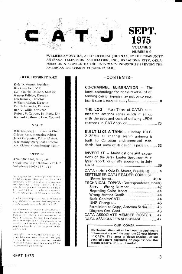
CO-CHANNEL EL IMINATION - Thelatest technology for phase-reversal of of -fending carr ier s ignals may not be so new;bu t i t su re i s easy to app l y ! . . . . . . . . . . . . . . . . . . . . . . . . . . . . 10
THE LOG - Part Three of CATJ's sum-mer- t ime antenna ser ies winds i t a l l upwi th the pros and cons of ut i l iz ing LPDAan tennas i n CATV se rv i ce . . . . . . . . . . . . . . . . . . . . . . . . . . . . . 25
BUILT L l l (E A TANK - L indsay 10LE-213FMU a l l channe l sea rch an tenna i sbu i l t t o Canad ian env i ronmen ta l s tan -da rds ; bu t some o f i t s des ign i s puzz l i ng . . . . . . . 33
INVERT lT - Modi f icat ions and expan-sions of the Jerry Laufer Spectrum Ana-lyzer repor t , or ig inal ly appear ing in JulyCATJ . . . . . . . . . . . . . . . . . . 39CATA-tor ia l (Kyle D. Moore. President) . . . . . . . . 4SEPTEMBER CATJ READER CONTEST
(En t r y f o rm) . . . . . . . . . . . . . . . . . . . . 40 -ATECHNICAL TOPICS (Correspondence, br ie fs)
So r r y - Wrong Number . . . . . . . . . . . . . . . . . . . . . . . . . . . . 42Begarding Color Adder. . . . . . . .44Wrong Au tho r C red i t . . . . . . . . . . . . . . . . . . . . . . . . . . . . . . . . 44Back Cop ies /CATJ . . . . . . . . . . . . . . . . . . . . . . . . . . . . . . . . . . . . 44UHF Chan9es . . . . . . . . . . . . . . . . . . . . . . . . . . . . . . . , . . . . . . . . . . . . 45Permiss ion to Copy, Antenna Ser ies. . . . . . . . . .45D iag ram One Goo f . . . . . . . . , . . . . . . 46
CATA ASSOCIATE MEMBER ROSTER.. . . . .47CATA ASSOCI ATE'S SHOWCASE . . . . . . . , , . . . . .47
OUR COVER
Co-channel e l iminat ion has been through many"phases and crazes" through the 25 year historyof CATV. The latest is 'down-phasing' ,
as ourdetai led report beginning on page 12 here th ismonth reports. (P.S. - l t works!)
3


casional breast or lots of bed-sheet coveredmotion, but i t is not expl ici t) . R f i lms get theirrat ings primari ly because of their language.Blazing Saddles, for example, could have eas-i ly been a G or GP f i lm i f the language hadbeen more careful ly control led. The visualsprobably would f ly alr ight as the f i lm camefrom the movie studio.
So here we are with a strong suit of R filmson pay-catr le. FiIms that get their shock-valueby using language not found on WaIt Disney.Now, how do we as an industry handle pay-ca-ble? Many systems simply set aside channel"R" (or 12, or whatever) for pay-cable, andinstal l a signal-el iminating trap device at thesubscriber's home. The trap, being a creationof man, has parameters of i ts own. I t func-t ions by trapping out ( i .e. el iminating) thevideo on the pay channel. But the audio, well ,i t r ides through almost as i f the trap were notthere. Traps are not very secure "security
dev ices . "
So R f i lms, a staple of pay-cable, lose theirvideo but they retain their audio. Becausethat is the only way we can make the inexpen-sive subscriber traps play.
Now go into a family-oriented home thathas elected not to take pay-cable. Switch tothe pay-cable channel. And I isten. Listen f irstto the language of the R rated f i lm, and thenl isten to the language of the home's parents asthey t ry to exp la in to the i r s ix o r seven yearolds why those words are coming out of theirTV se t speakers .
Cut now to the cable TV system off ice andl isten to the telephone cal ls from people whoare offended by the audio of Blazing Saddles.Listen as they patiently explain that as par-ents they cannot sit on top of the family set 24hours a day to keep their kids from tuning i tin. Listen as they complain that the kids don'tunderstand that they are not supposed to getthat channel, and that when they switch to thechannel and the picture is bad, the kids dowhat any kid wiII do; he f iddles with the f inetuning trying to make the picture material ize.And wh i le he f idd les , someone says F . . . .
We have no beef with pay-cable. Many sys-tems need i t to swim; without i t , they maywell sink. But we think that as long as we asan industry have this technical dif f iculty, andas long as pay-cable audio is going intohomes, we had better be prepared for thatf irst di luge of letters that FCC ChairmanWiley receives complaining about our pay-ca-ble language; language which the family ex-pl ici t ly did not want when they said "no" tothe pay cable offering. This sort of problemcould create a "need" for the FCC to step intothe "censorship arena" of pay-cable movieprogramming. Do we want o r need tha t? Ithink not. Let 's f ind a technical solut ion to thistechnical problem. . . and fast!
S E P T 1 9 7 5
Glen ShaferGeneral Manager,1 3-years ManagerWestern RegionalTechnical Operationsfor Jerrold
Joe E. HalePresident,
1 6-years inCATV engineer-
ing, veteranSystem Operator
Cable Dynamics Incorporated now offersrapid, high quality, low cost Repair Servicesfor :
r HEADEND EOUIPMENTr CATV DISTRIBUTION
EOUIPMENTI CONVERTER RE FURBISHING
r MATV EOUIPMENTr S IGNAL LEVEL METERS
Manufacturers, MSO's, IndependentOperators . . . save time, save money, saveaggravation. Put CDI SERVICES on yourtechnical support team! Write or calltoday for complete information.
A Division ofCAELE DVNAMICSINCORPORATED
501 Forbes Blvd., South San Francisco,California 94080. Phone (41 5) 873-2906
t


1. 3/8-32 rotating coupling nut
2. Outer housing hex crimp ara.
3. Cable strain relief crimp.
4. Inner R.F.l. sleeve.
5. Cable foil under R.F.l. sleeve.
6. Cable braid over R.F.l. sleve.
7. Envircnmental sealing area.
One size 56 fits all RGU 56
One size 59 fits all RGU 59
I(
I
II(
a(l,I
. ,1I
,Ct
. t...;
, }rtr,tr ' f
a',Il,.xrF
'ii
C
CATJ for

If yot{vebeenwaitingfor achancetosellparyry
this isit.
The sa tc l l i t c i s rcady to de l i vc rprogramming And Scienti f ic Atlant:r 'scarth stat ir)r-r is rcady to rcccivc i t . Whichm ( ' : l l t s y ( ) u r c h i l n c c t o 1 1 1 t l a . n l ( ) n e ys c l l i r r g p r r y T V h r r s f i n r r l l y r r r r i v c t l . I t ' sclnitc an imprcssive chancc, too. Evcnc o n s c r v a t i v c p r o j c c t i o r - r s c a l l f o r al , l t r ' n , r t t e r r , r l g r r r w t l r r r t s t r h s c r i I t i o r r sng l r t t r ( )n t thc \ t l l r t .
Ancl how,.kr you get i l ' l to pay TV?Wc'vc madc i t as s i rnp le as poss ib lc w i thol lr carth stat ion. Yor,r just acld i t ontoyolrr cxist ing CATV systcl l tr you wor-r ' tbc rcp lac ing or dup l i ca t ing rny o f thcr t 1 t t i p 1 1 1 1 1 1 1 y r ) u r l r c r l ( i y h , r v . ' . W r ' ' l l l r e l l ry r r t t l i g t t r c { ) u t i n i l r l v i l n c e e x : t c t l y w l l i l tc t r r t f i g t t r : r t i o r r y o r r ' l l n c e t l ; j u s t s ( ' n d u syour coord ina tcs .
Thc carth stat ion consists of ar-r
," a " ii'* iii,ii"',iirp tlii"i,',1 ;l;"i ;;;; :i iiproperly interconncctcd for opti lnrur_ systcm pcrformar-rc-. I t 's cxtraordinari lysir lplc to opcratc and n-raintai i , ar-rd t l"rc constr irct ior-r ancl ir-rstal lat ion costs arcmoderate. Also, i t 's designetl to be crrnrI letcly f lcxible. Ar. lci i t ional fcrrturcs orc i rp r rb i l i t i es c r tn bc r rdded: rs the r r t .e t l r r r i s r .s .
Hirs our carth stat ion aircadv nrovcn i tsclf Jre l iab ly in p laccs l i ke A laska and Sa i rd i Arab iafo r scvcr i t l yc l t rs . Ar rd o f cor r rse t l re sys t t 'n r i sbacked by our CATV technrcr r l i rn t l sc rv iccorganiz:rt ior-r. Wc havc nine salcs and scrviceo f f i ces th roughout the Un i tcd Sta tcs , w i t |cmcrgency assistancc avai lablc 24 l .rours a day.
We 'vc preparcd :r brochurc to int lrcluccyou to the Scicnti f ic Atlanta carth tcrminalThc sooncr you rr ld i t , the sooncr you can bcginplanning your luturc i l pay TV. Writc f or ir copyoi thc brr)churc, r)r for morc information on
Abt_ iifiEbb% rlistributi on and hcad end sys tcr.r.r s
rultenna, i ts associatcd fccd and lnol lnt
Absolutcly. I t 's l .recn pcrforming
cal l fay Lcvcrgood col lcct at
ScientificAtlanta
Complctc systems
S E P T 1 9 7 5
I--
I
S c i c n t i f i c A i l r n i i 1 n c . ] 8 1

II:
T
"\rus&\._
CARD MESSAGE SYSTEMLocol NewsPubl ic Serv iceAdver t is ing
Reol EstoteAuto SoleShopp ing Mo l lWont Ads
* Color or B lock ond Whi teThe MSI DATA MESSAGE un i t i s a compact , low-cos t and h igh lyrel iable device for the display of advert ising materials. Program.mingis s imp le . Cards may be 'ad-ded or de le ted w i thout p rogram. in te r -ruo t ion . The un i t accommodates a smal l co lo r o r monocnromecamera.The DM-50 system can accommodate up to 50 displays. mountedon holders d'esigned lor 41/q x 33/a inch cards. Preparation of aneftect ive advert is- ing display can be completed and inserted intoproper sequence in-a md,ttei of minutes using Polaroid photographs,snapshots, graphics, or typewrit len cards.Reliable long-term continuous operation is assured by the use ofheavy du ty bear ings , cha in d r ive , and te f lon gu ides .
Reproduction stabi l i ty is assured by a magnetic retainer at the baseof
'each display cari l holder which " locks" the picture in a f ixed
posit ion before the camera.In order to al low the system to be used in appl icat ions where i tsou tpu t i s a l te rna ted w i th the d ig i ta l da ta ou tpu t o f MSI equ ipment 'the ' DATA MESSAGE has been equ ipped w i th a dua l con t ro l t imer .This system al lows programming of display t ime devoted to eachcard as we l l as an
' independent ad jus tment o f the per iod o f t ime
in wh ich the d ig i ta l d isp lay i s p resented 'The rack mount des ign e l im ina tes los t f loor o r tab le space.a t yourheadend or s tud io . ine on tR MESSAGE un i t i s mounted in to as tandard 19" rack and is supp l ied w i th s l ide ra i l s . The chass is de-sign provides easy access to al l camera controls.
MSI TELEVTSION . 47aB SOUTH STATE STREET . SALT LAKE CITY, UTAH 841 07 ' PHONE (AO1) 262-447s
lL
i\\
1 0 CATJ for

In Lightning Vulnerable South Florida. . ."We wouldn't be without the Mini-Mizet. . . , ,
So says lVr. Wal ter 0. Welch, of South Flor ida Cable Televis ion, Boni ta Spr ings. "The U.S. Weather Bureau charts says wehave up t0 80 days of thunderstorms per year here. What that doesn'l tell you is that we otten get hit lwo 0r three times in i day,and then again at n ight for good measure!" noles Welch. "We have instal led the Brown Electronics Mini-Mi2er on al l of ourequipment, f rom the Weather Channel to our complete headend and al l of our p lant power suppl ies. N0, the l \4 in i - l \4 izer does notcure al l o l our problems, but we feel i t has cut our d i f f icul t ies wi th l iohtning and power company swi tching surges by no lessthan 50%. 0ne of our Mini -Mizers in our headend has recorded 1 43 surges in just s ix months; th i t is I 43 tuses we did ngt haveto replace, 1 43 t r ips we did not have to make t0 the headend, and possib ly a hal f dozen power supply fa i lures we did not have t0repair . "
Mini-Mizer has a ful l one year guarantee. l t is a patentedapproach to shunting surges off be{ore fuses blow or equi0-ment is damaged. There are several models, to handle virtual-ly any CATV power load; and for indoor 0r outdoor mountinq.Available tor 120 VAC and 240 VAC circuits. You need ioknow more about Mini-Mizer today!
BROWN ELECTRONICSArtemus Road, Barbourvi l le, Kentucxv 40906(606) 546-5231
Our new Security Shieldstops people from stealingyour CATV equipmentand service.
It prevents connection changesof mul t i -dwel l ing insta l la t ions. Andit protects "F" connections.
For just a few cents, stop therip-off that costs you thousands ofdollars. Write or call us today. (607)739-3844.
ncE L E C T R O N I C S , I N C .
901 South Avenue, Horseheads NewYork 14845
1 1SEPT 1975
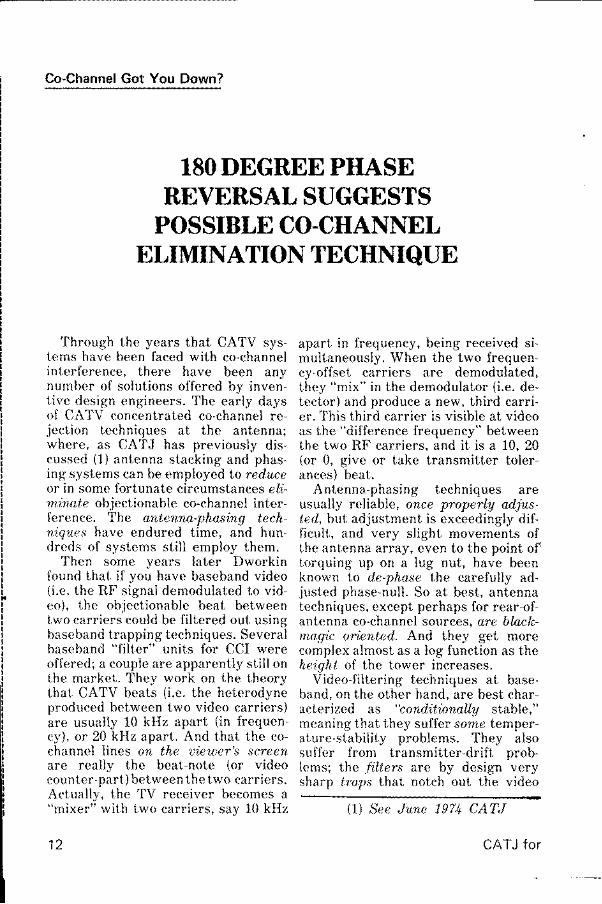
180 DEGREE PHASEREVERSAL SUGGESTS
POSSIBLE CO.CHANNELBLIMINATION TECHNIQUE
Through the years that CATV sys-tems have been faced with co-channelinterference, there have been anynumber of solutions offered by inven-t ive design engineers. The early daysof CATV concentrated co-channel re-ject ion techniques at the antenna;where, as CATJ has previously dis-cussed (1) antenna stacking and phas-ing systems can be employed Lo reduceor in some fortunate circumstances el;i-minate objectionable co-channel inter-ference. The antenna-phas'ing tech-ni,ques have endured time, and hun-dreds of systems still employ them.
Then some years later Dworkinfound that if you have baseband video(i .e. the RF signal demodulated to vid-eo), the objectionable beat betweentwo carriers could be filtered out usingbaseband trapping techniques. Severalbaseband "filter" units for CCI wereoffered; a couple are apparently stil l onthe market. They work on the theorythat CATV beats ( i .e. the heterodyneproduced between two video carriers)are usually 10 kHz apart (in frequen-cy), or 20 kHz apart. And that the co-channel lines on the uieuter's screenare really the beat-note (or videocounter-part) between the two carriers.Actual ly, the TV receiver becomes a"mixer" with two carr iers. sav 10 kHz
1 2
Co-Channel Got You Down?
apart in frequency, being received si-multaneously. When the two frequen-cy-offset carriers are demodulated,they "mix" in the demodulator (i.e. de-tector) and produce a new, third carri-er. This third carrier is visible at videoas the "difference frequency" betweenthe two RF carriers, and it is a 10, 20(or 0, give or take transmitter toler-ances) beat.
Antenna-phasing techniques areusually reliable, once pT"operly adjus-ted, hut adjustment is exceedingly dif-ficult, and very slight movements ofLhe antenna array, even to the point of'Lorquing up on a lug nut, have beenknown t"o de-phase the carefully ad-t'usted phase-null. So at best, antennatechniques, except perhaps for rear-of-antenna co-channel sources, are blnck-magic oriented. And they get morecomplex almost as a log function as thehe igh l o f the tower inc reases .
Video-filtering techniques at base-band, on the other hand, are best char-acterized as "conditionally stable,"meaning that they suffer some temper-ature-stability problems. They alsosuffer from transmitter-drift prob-lems; the filters are by design verysharp lrnps that notch out the video
(1) See June 1971 CATJ
CATJ for

baseband in the frequency region ofthe beat ( i .e. at 0, 10, or 20 kHz). Theymustbe sharp to take out the beat andstill, leaue the required video informa-tion intact. By being very sharp, theycan lose a great deal of their effective-ness by drifting a little bit down or upin frequency, as a function of operatingenvironment temperature, humidity,or both. And, being very sharp, if theoffending transmitter and/or the de-sired transmitter drift (and they all doto some extent), the frequency of thebeat betuteen the two carrierschanges. What may be a nominally 9kHz beat one day could easily be an 11kHz beat the next day. Not enoughmove to cause the FCC to move in, orthe video co-channel interference beaton the unfiltered screen to change itsapparent form to the average eye, butenough to cause the sharp trap/filterpre adiusted for 9 kHz to lose its holdon the beat-produced "carrier."
So the pot at the end of the co-chan-nel interference rainbow has neverreally been found . Peopln stil l haueproltlems ui,th CCI, and so consequent-ly inventive engineers are stil l tryingto soht<: the problem.
In the August 1974 issue of CATJ,the magazine queried readers as towhat their biggest problems were. Avery high percentage (over 15o/o) rated"co-channel interference" as one of thetop problems; it made the top fiveproblems for the year. So while wemay only talk about it in hushed tonesand behind closed doors, clearly theindustry for all of its other problems(technical and political) has stil l notcome to grips with a problem that ori-ginated in 1948. Co-channel is stil l with?/s.
Phase It
Television reception presents uni-que problems for co-channel interfer-ence. The television-reception industryis saddled with AM (ampl i tude modula-
S E P T 1 9 7 5
tion) in the video carrier, and when acarrier is amplitude modulated, wejust "ask for" a beat to develop be-tween two carriers that happen to beclose in frequency. In AM radio broad-casting, you can "hear" the beat, espe-cially on the high end of the AM bandat night (in the 1,200-1,600 kHz range)when "skip" is in. The Mexican sta-tions don't maintain the same trans-mitter-frequency tolerances we do, forenamplp, and when a Mexican on 1548beats with a U.S. station on 1550, wehear an audible 2 kHz beat note be-tween the two carriers (it sounds like a2 kHz shrill pitch interposed in withthe audio from the 1550 or 1548 kHzstat ion[s]) . U.S. and Canadian stat ionsstay close enough to the same nominalAM frequencies (i.e. such as 740 kHz)that the beat, if audible, is a low-fre-quency rumble, such as 50-100 cydesper second.
FM stat ions, being FM (frequency)modulated at a rate approximating themodulation product of the music ortafk presented, don't present Lhe sameproblem. It is the nature of an FM de-tector that the strongest audio/carrierpresent captures the discriminator,and uou are not e'u)(rre that a second(interfering) station is present until itbecomes strong enough (or almoststrong enough) to capture the discrim-inator. Then, as if someone threw aswitch, the audio of carrier B capturesthe discriminator, and the audio of sta-tion A is gone.
Television-broadcasting standardsin some other parLs of the world in-clude FM modulation of the video. Con-sequent ly, in those areas (much ofEurope for example) co-channel inter-ference, as u;e knoul ff, does not exist.Remember that with FM (modulat ion)the modulation product on the strong-er (by signal voltage) carrier is the onethat "captures" the discriminator; theother mod,ulation producl (and the car-rier) is all but totally ignored as lnng asi t is weaker.
l--1 3

IIIIIIIIII
Then we have the offset problcm.Television stations throughout theUnited States, Canada, and along theborder areas of Mexico are assignedon purpose by the FCC Lo operate onfrequency offsets. That is, ratherthan assign oll channel 2 stations to55.250000 MHz, the Commission as-signs Pittsburgh channel2 (KDKA) to55.240(000), Baltimore channel 2(WMAR) to 55.260(000), and New Yorkchannel 2 (WCBS) to 55.250(000). Thestations are then 10 or 20 kHz apart(New York is 10 kHz from Pittsburghand Baltimore, while each of these twois 20 kHz from each other). This is doneon the theortt that if a carrier-beatmustbe produced, the video beat pro-duced between carriers 10 or 20 kHzapart in frequency is less objectionableto the uieuter than the beat producedbetween two carriers nominally no (0)kHz anart .
Al l 'of this has been covered ratherextensively previously in CATJ (2\.
Then there is the leuel problem. Abeat (i.e. something objectionable onthe TV screen) shows up when a non-desired carrier is as much as 40 dBlower in signal level at the processor/receiver terminals than the desiredsignal. Minus 40 dB relnt iue to the de-sired signaf can be a lnng utays doum.Hanging large sensitive receiving-an-tenna arrays 500 feet above ground, oratop a mountain, is one heck of a goodway to pick up tuto or more stat ionsper channel, even if the non-desiredstations are down 20-30-or 40 dB fromthe desired station. In real life, if -20dRmV produces a marginally accepta-ble picture from CATV receiving an-tennas, a -60 dBmV non-desired sig-nal on the same channel produces anrtticeable beat on the screen. Minus 20dRmV is 100 microvolts, nothing towri te home about. Minus 60 dBmV is 1microvolt ; that is hard to see even on a$12,000 spectrum analyzer! In fact, youcirn probably see it quicker when it isbeating against a -20 dBmV desired
1 4
signal than you can searching for bgi,tself in the "noise grass" on a spec-trum analyzer, even if it is the onlysignal on the channel.
In other words, the TV receiver (ev-en the $69.95 discount store 9-inchblack-and-white portable) can be a bet-ter co-channel signal finder than a$12,000 s /A .
There have been, from time to time,serious proposals to the FCC frombroadcasters. These broadcasterswant to ertend their deep-fringe cov-erage, and they know that given mod-ern-home deep-fr inge receiving anten-nas (or cable receiving antenna sys-tems plus low noise pre-amps), i t is not
(21 See June 1971 CATJ
0/10120 kHz CCI
Stations operating on nominally thesame offset (i.e. usually classified asminus [10], zero, and plus [10]) produceone type o f CCI pa t te rn . I t var iesslightly between receiving situationsbecause stations do not maintain pre-cise frequency control, and the beatpattern displayed by the receiver is de-pendent upon the lrequency separotionbetween two (interfering) carriers.Generally, it appears as the first photosnown.
Stations operating on offsets whichare nominally 10 kHz separated pro-duce a different kind of visual beat.Again, this varies somewhat because ofexact station operating carrier fre-quencies, but it generally looks similarto the second photo shown here.
Finally, stations operating with off-sets which are nominaly 20 kHz sepa-rated have yet another beat appear-ance. The exact beat appearance mayvary slightly from that shown.
Knowing the beat-separation be-tween stations is very important, toinsure that the signal you are erectinga sense/test antenna for is the one thatis really causing you the problem. Oneway to be sure is to have a copy of theCATJ WTFDA TV STATION GUIDE;only $6.50 postpaid from CATJ.
CATJ for

signal level, i t is co-channel, that is eat-ing into their beyond-B viewing con-tours. One way, from the broadcasterend, for this problem to be rectified( i .e. co-channel ef fects to be toneddown or el iminated) would be for al lTV stcttions on a given channel to oper-ate exact ly on the same channel f re-quency assignment. By exact, we mean55.250000(000). This is not possible aslong trs each channel (2) t ransmit terenrploys its own local crystal (control-led) oscill;itor to derive its operatingfrequency. Try as the var ious channel(2) transmit ters might, they could nev-er (al l ) stay on 55.250000(000) simul-tuneo'uslq i f each cont inued to indepen-dentfy derive its outn local oscillatorfret luency source.
One solation to this problem is a na-t'inn.aL phase-locked frequency stan-dard, der ived from a Rubium standard,for example. Then i f nl l stat ion crystalosci l la lors stayed phase-locked to amaster s'inqle-so'urce oscillator, therewould be frequency (and phase) coher-ency al l across the nat ion. What thatwould accomplish is thi i t whi le therewould st iLI be co-chunnel interference,it would be more kke the kind experi,enced with I . 'M broadcasters and re-ce ivers; the viewer would not bee,u)a're ol the presence of the secondsignal or stat ion unt i l i t became strong-c r l l t h e r e c e i v e r t h a n t h e o n e h e w a swatching, whereupon the detectorwould simply switch to detect ing theinterfer ing st :r t ion's modulat ion, s imp-ly because i t was now stronger thant h t ' des i red s ta t ion .
But alas, in spite of some efforts bysome broad,casters to even start re-gionalized frequency-locked operationwith their neighbors, the FCC hasshown l i l t le interest in pushing oradopt ing the project
So here we are, with those funnynominaLlg 0, 10 kHz and 20 kHz line!running through our pictures everyt ime the weather changes or the "skip 'comes in. And the phone r ings off the
hook as subscribers ask us to "take
Lhose lines out of the picture."Into this scenario enters a fairly new
comer in the CATV marketplace: Mi-crou)o,ue Filter Company of East Syra-cuse, New York. And for approximate-ly $250, they offer to solve your co-channel problem.
How would they accomplish this/ Byphasing the interfering signal "out ofthe picture" (pardon the pun) with amagic l i t t le grey box.
I'-unn!/ Cigarettes in East SAracuse
We don't know for a fact, but wesuspect that someplace someone hasaccused Glyn Bost ick and his crew atMicrowave Fi l ter Company of puff ingon "[unny cigarettes." Anyone who hasgrown up in the CCl- laden industryknows through tr ials, t r ibulat ions, andtens of hours of antenna pruning thatco-channel interference is not solvedwith lunny cigarel tes (not unless voucirn get euerAone in toum to smokeLhem simultaneously!) .
O , n o a c o - c h a n n e t E t i m i n a t o r
And when CATJ asked usual ly co-operative Mr. Bostick for his assis-tance in looking at how the industrywirs responding to his model 2903 (ser-ies) "co-channel el iminators." we ful lvexpected him to tell us to get losf.Ruther he responded by provlding uswith a file full of letters (some good,some bad) from users and the completel ist of everyone who had ever ordereda 2903 "el iminator"; including thosew h o r e t u r n e d t h e u n i t s a f t e r - a f i e l dtr ial . That kind of openness surpr isedus. I t turned out that Glyn Bost ick hadnothing to fear from our "prying" and
!_:="'n'u1 5

he knew i t .The 2903 series Co-Channel Elimina-
lion units are very cleverly designedphasing devices, not unl:ike the fabled"l ine stretchers" of olden days (remem-ber those Bruno?). Many years ago(more than ten) we got a first-classlersson from Bruno Zirconi at Scakt Ra-d,i,o in San Leandro about line stretch-ers. We had a nasty channel 7 co-chan-nel problem, which we had attemptedto solve by stacking four channel 7Yagi-Uda antennas in a horizontal for-mat ( i .e. s ide by side, four wide). Wehad plaved and played and played fordays moving one antenna, then anoth-er antenna, and on and on. Sometimeswc had i t , then we lost i t . Bruno cameto our rescue with a coaxial l inest,rctcher, which let us leave the anten-nas ulone, and by crtrnking on the l inestretcher we were able to insert vary-ing anrounts of cable (a cent imeter at at inre) into the phasing l ines unt i l wefound the r ighl combinat ion to phaseout lhe non desired signal.
The 2903 series box slorls from the,som.e premise, although creator Bos-slick has a different set of parametersin his end "box." We' l l f ind out whvand how short ly.
Do As I Satt
Our f i rst introduct ion to the 2903was with a fel low down in Texas whohad ordered one shortly trfter theywere announced. "Hout does it utork?"wc rrsked him at the t ime. " I t doesn't ,"he rersponded.
So we took a look at what he wasdoing. The 2903 had been installed inthe down line of the desired stationantenna array. There are two knobs onthe 2903, and naturally any good oper-ator immediately inserts the 2903 inhis downl ine and starts crankins onthe two knobs as soon as the un i l a r -rives. Only, as the Texas operator hadto ld us , " i t doesn ' t work . " A t lBas t no tthat uazt. Oh, the picture content
1 6
changes all right as you crank on theknobs. If you crank on the one marked"Attenuation," the picture drops clearout ("now that eliminated the CCI," myTexas friend remarked). Not just thenon-desired signal, but both signals.Then if you bring the Attenuation con-trol back up to full clockwise and crankon the other knob (marked "Phase"),
the picture changes content-a littlebit. But the CCI and the desired signalchange at the same time."Let's sit down and read the instruc-tions," we suggested to our Texasfriend. "The darned thing doesn't work. . . what is lhere to read?. You just in-sert the downline into the 1n spigotand loop to the processor out of theolher one," he murmured as he walkedaway. "At least I didn't have to climbthe tower to find out it doesn't work,"he was heard to utter as he disap-peared into the outside world.
So ute read the 'insttactions. It turnsout that the 2903 was installed improp-erly. Something we later found wasprobably true with dozens of other2903 units shipped out by Glyn Bos-tick, if our followup to his sales list isindicative of what reallg happened outin the f ie ld.
It turns out that the unit must (re-peat must) be installed according tothe instrucfions. There are no short-course stop-gap approaches. Eitheryou do i t r ight, as shown in Diagram 1,or you don't bother to do it at all. Andif you do it right, we found out fromseveral hundred hours of playing(more about that shortly), there is onlyone way you can fail. That we will alsocover.
In Diagram 1, we have the desiredstation with its outn ttntenno, connec-ted to the headend processing equip-ment through a 6 dB directional coup-ler. The desired station signal feedsthrough the directional coupler via theinput/output ports (i.e. not throughthe 6 dB down port) .
ICATJ for

C H A N N E L P R O C E S S I N GEOU IPIVI E NT
I
DIAGRAM 1Then we have a separate, second an-
tenna, erected primarily to providesignal from the non-desired station.Now this non-desired signal can comefrom a same-channel source (i.e. trueco-channel) , or it can come from an ad-jacent channel signal. This non-desiredsignal, co-channel or adjacent channel,is then fed through a bandpass filter(something to clean up off-frequencysignals) and then through a 2903 (2903-2/6 is tuneable for channels 2-6; 2903-7 /73 is tuneable for channels 7-13.UHF models are also avai lable.) . Then.if required, the non-desired signal goesthrough an amplifier (that's right. . .anampkfier) and into the 6 dB directionalcoupler, through the 6 dB port.
The equipment on the desired sta-tion is just as you nou have installed;plus, the addition of the 6 dB direction-al coupler.
The equipment on the non-desiredstation breaks down this way. The an-tenna is to pick up the non-desired sig-nal. The bandpass f i l ter is to ensurethat you end up going into the subse-quent amplifier and directional couplerwith primarily just the channel youwish to trap or phase out. We foundthat you could eliminate the bandpass
S E P T 1 9 7 5
filter z/you put a good high-selectivitysingle-channel strip amplifier (a B Tunit withozlt mating bandpass filters isNOT adequate) at the ampl i f ier posi-tion. The 2903 is Lhe magic box.
The 2903 deliberately seeks out asampkz of the non-desired signal. On itsown antenna yet. Then through the2903 the non-desired signal is insertedinto the l ine with the desired signal,af ter reversing Lhe phase of Lhe' nondesired signal. That is pretty simple,and that is the way i t works. You musthave a level of non -desired signalthrough the "sense" antenna that is atleast compatible in level with the samenon-desired signal coming down thedownline uti,th the desired signal. Ifyour desired stat ion antenna is pickingup 50 microvolts ry' non-desired signal,you real ly need to be in the same gen-eral bal lpark with the non-desired sig-nal through the "sense" antenna ar-rangement, i f you want the phase can-cel lat ion to work.
With the installation rigged up asshown (again, follow the directions,and the only valid substit'ution we sug-gest is elimination of the external BPFz/you have a first-class highly selective
1 7

iIIIIIIIIIIIIII
on-channel lnot heterodyne] proces-sor), you adiust as follows:
(1) Place ATTENUATOR knob ful-ly clockwise (minimum attenua-t ion);
(2) Rotate PHASE knob for great-est erasure of the co-channelinterference (the point of era-sure will l:e fairlg broad usual-ly, meaning that you don't haveto sit there and breathe on theknob a l i t t le at a t ime):
(3) Rotate ATTENUATOR knobcounter-clockwise for the pointof best (usually total) erasure ofthe CCI or adjacent signal;
Not,e: I f i t turns out that your Lreslnoint of CCI erasure with theATTENUATOR knob is ful lyCLOCKWISE ( i .e. againstthe knob stop), then you im-mediately know that yoursense antenna signal is notstron.cl enough. Correct thathe fore cont inu ing .
'lhen you go back and refine thephasing by touching up the ATTENUATOR and PHASE knobs. That iso,ltout all t.here i,s to it.
Net.uro,l Terxl,en.cy
If the operator gets by the quickie-dt:s ire to insert the 2903 into the down-l ine of his desired signal ( f i rst impulsefresh out of the hox; u;rongl) and de-cides that he has to go to some (smal l)effort to .firul out if it 'utorks, the next"quickie-stop" is to rotate the searchantcnna toward the non-desired signaland usin,g ft as a "sense" antenna, in-sert the 2903 without ampl i f ier orbandpass f i l ter into the lash-up "more
or less" as shown in l ) iagram 1. This isreal ly not recommended; you probablyunn.'t haue suffi,ci,ent signal on thesearch antenna to do the job, and whi leyou may get some erasure, you prob-ably wi l l f ind that the ATTENUATORknob is showing besl erasure with theknob fully cLocku;ise. Remember what
1 8
the note previously quoted said: "If theATTENUATOR knob shows best era-sure when it is fully clockwise, youdon't have enough sense signal." Be-Lieue it.
At some point a little trust has to
l n s i d e t h e 2 9 0 3
CATJ for

creep in, and in addition to being sobenevolent as agreeing to "try" the2903 from Microwave Filter to "see if itworks," you are also going to have tocommit to getting together some sem-blance of equipment to follow the in-struct ions in Diagram 1 and here.
Everyone has a right to be skeptical.So let's deal with those situationswhich CATJ research revealed docome up where the 2903 plus the rec-ommended installation will not cut themustard. There are a couple of situa-tions like this.
(1) Too-cLose heading-When thenon-desired signal gets tooclose in receiving-angle to thedesired signal, you end up"down-phasing" the desired sig-nal right along with the non-de-sired signal. Microwave Filteradvises that a ten-degree angu-lnr separation between signalsis about as close as you can getand stil l keep the desired signalfrom being too "hot" on the"sense antenna." In our experi-ence, ten degrees mag be tooclnse. It all depends upon thetype of antenna array you arewilling to install for your senseantenna. If you horizontallystack a couple of Logs or Yagi-Uda antennas and space themso that they antenno-phase-nulltoward the desired signal (i.e.purposefully go after the non-desired signal), you might getdown to 15 degrees z/ you arecareful. There is one exceptionto this rule which we will coverlater.
(2) If you are going after the adja-cent chonnel (rather than co-channel) with the 2903, thebandpass filter and amplifiersandwiching the 2903 must befor the adjacent channel (thinkabout it; iL uill all make sensein a minute).
S E P T 1 9 7 5
(3) I f the test (sense) antenna andthe desired channel antenna ar-ray are physically close togeth-er, there can be coupltng be-tween the two antennas. Thatis, the big monster array for thedesired channel couples (radi-ates through the air or re-radi-ates) the desired signal into thesense or test antenna. This re-sults in too much desired signal,on the sense or test antenna.We found out that antennasplus or minus 50 feet in heightbut separated by as much as200 feet horizontallg (on adja-cent towers) coupl,e betuteenantennas much more than wehad ever previously suspected.In our CATJ test environment,rotating a tower-top search an-tenna on one tower 200 feetfrom another tower-top-moun-ted search antenna destroyedphase adjustments on the 2903.We got the erasure back by re-adjusting the knobs on the 2903nowever.This tells us that if you golhrough the proper exercise ofhanging a separate sense ortest antenna, that before youbutton everything up, rotateyour own search antenna, evenif i t is nol connected to any-thing in this system, and watchthe erasure level on a monitor.You may have to warn person-nel that rotating the search an-tenna affects the sense-antennalevels and that readjustment ofthe 2903 system is necessary c/-ter playing with the search.
This also tells us that if youdo some tower work and movesome antennas around-evenantennas not part of this sgs-tem or not close to the systemantennas-you had better re-check adjustments of the 2903
t-1 9

before walking away from theheadend.
In words of a few syllables, phase istrickg stuJf!
One of the popular misconceptionsabout the 2903 type of system is thatthe adjustments you make are onlgglood f.or the levels being experiencedby the sense/test and desired signalantennas for that moment. Stop andlhink about what it is you are reallydoing. The input level from the non-de-sired can go uaA up (up to the pointwhere it is stronger on the desired an-Lenna than the desired signal) and waydown (down to the point where you nolonger have sufficient gain in the 2903system to function properly), and theco-channel (or adjacent channel era-sure) is not aff.ected. It is not leuelwhich is bucking out the non-desiredsignal, i t is phase.
Can the 2903 go outside? A betterquestion is uthy u;ould, gou uant to putthe 2903 outs'ide? Re-look at Diagram1 .
There are two knobs on the 2903.How often do you have to readjustthem? We don't honestly knout. We doknow that it is not very often. It willdepend upon your own headend envi-ronment and one other factor overwhich you have no control. If yourheadend is reasonably temperatureconstant, we see no reason (and foundno sign) for instability. Neither doesMicrowave Filter Company; and theysay so in their literature.
There is one thing that uill foul youup, but it may not happen nearly asoften as some might have you believe.Under strong signal conditions (i.e.when the non-desired signal comeslDaA up in level), the phase of the non-desired as it approaches your desiredsignal and sense/test antennas maAchange; change relntiue lo what it wasthe day you set the whole thing up andwalked away. If that happens, thenyou will need to re-tweek the PHASEknob on the 2903. And,, u,hen signals goback dou;n to their normal levels, youwill have to return to the headend andre-tweek it back to where it was whenconditions were more normal. But, aswe noted, in tu.to months of trging, un-der some widely varying signal condi-tions, we only found this to happenonce, and then we wete not totally cer-tain that is what happened.
Users Speak
To put together this report (and weare grateful to several systems whoprovided us with data to add to ourown two months of testing), we wentto Glyn Bostick's user list. Here issome of what we learned:
(1) Houtard Leuis, WinchesterCATV, Winchester/Lex'ington, Va. -"We have four off-air ghosts on a chan-nel 10 signal at Lexington. The ghostsvary in level with the weather and arenot always bad. We installed the 2903and found that we could eliminate one
I
2903 Specs
Models-2903-2/6 . ..2903 7 /r3
. Tuneable channels 2-6Tuneable
channels 7-132903-UL . . .Tuneable channels 14-482903 UH . . .Tuneable channels 49-83
S i z e . . . . . . . . 3 . 1 2 x 3 . 6 2 x 9 . 1 2 "Impedance . . .75 ohms. in/outPhase Range 180 degrees (min)
Attenuation Range . .40 dB (min)
Price-V H F M o d e l s . . . . . . . . $ 2 4 5 . 0 0U H F M o d e l s . . . . . . . $ 2 9 0 . 0 0
Delivery-VHF Mode ls . lweekU H F M o d e l s . . . . . . . 2 w e e k s
Manulacturer-Microwave Filter Company, Inc.6?43 Kinne Street, E. Syracuse, N.Y.130571Er5 / 437 4529\
20 CATJ for

l . S w i t z e r T e s t s - C f 1 O O M l { z , v e r t i c a l s c a l e l Od B p e r d i v i s i o n , h o r i z o n t a l s c a l e 5 M H z p e r d i v i s i o n
l . S w i t z e r - s a m e v e r t i c a l s c a l e , h o r i z o n t a t 1 O Ok H z p e r d i v i s i o n
of the two serious trailing-edge ghostscompl,etelg. It just went away. Thenon-desired ghost signal path elimi-nated was approximately 35 degreesoff of the desired signal path. But wecould not solve the main objectionableghost with our present antennas; it ap-pears to be approximately 10 degreesoff of the desired signal heading. Wewere aboul Lo send the unit back- untilwe experienced a day of severe co-channel from a channel 10 station downin North Carolina. We put the 2903 onthe search antenna, rotated the searchonto the North Carolina offending sig-nal, and adjusted the 2903. The CCIwent compl,e.telg auay on our cable sig-nal. That convinced us; we kept the2903."
S E P T 1 9 7 5
l . S w i t z e r - s a m ep e r d i v i s i o n
l . S w i t z e r - s a m e v e r t i c a l s c a l e , h o r i z o n t a l 2 O k H zp e r d i v i s i o n
Howard also advised that he is work-ing with Lindsay to design an exceed-ingly narrow beamwidth antenna sys-tem to try to chop out the non-desired10-degree off-main-path ghost signal.
\21 I. Suitzer, Staitzer EngineeringSeruices, Mississauga, Ontari.o-"W eran some tests on the 2903, setting itup as a notch reject filter, using ourH-P tracking generator/spectrum ana-lyzer. It appears that 65 dB of attenua-tion is possible over a uerA narrou)bandwidth. Our application is for re-jecting a strong undesired adjacent-channel FM signal. FM deviation runsto */- 75 kHz, and we were con-cerned about the rejection over the 240MHz or so of occupied spectrum. ItIooks like we should be able to get
v e r t i c a l s c a l e . h o r i z o n t a l l M H z
r21

about 40 dB of rejection. Our next con-cern is stability with time and environ-ment . "
"What is really needed is a phase-lock loop of some kind to maintain max-imum cancellation. It requires automa-tic electronic phase-and-attenuationcontrol. Our past experience with'bucking' systems like this (we used touse step attenuators and General Ra-dio l ine stretchers) is that they need tobe adjusted everyday."
(3) Robert E. Johnson, GeorgetoumCable TV, GeorgetouLn, Ky.-"Wemade the usual mistake, and after in-stalling the 2903-U /L (Editor's note-llHF version for channels 14-48), wehtrd no results. After thinking it over,we reread the instructions and did itaga in . "
"The 2903 is now doing a beautifuljob and has completely solved ourproblem in eliminating adjacent-chan-nel interference. We are only 10 milesfrom channel 18, and we needed to re-ceive a very desirable channel 19 about60 miles distant. We were about to en-ter into a very expensive tr ia l-and-er-ror antenna-phasing project recom-mended by another equipment suppl i -er. Best of al l , the 2903 puts the 'con-
trols ' in the headend, in the hands ofthe system personnel, not out on thetower at the mercy of the elements."
For-ms of Interference
During the summer months, manysystems (read majoritg) experience co-channel interference on low-band chan-nels during periods of something affec-tionately known as "Sporadic-E skip"transmission (see CATJ for October7974). Sporadic-E skip is a transmis-sion mode via the E layer of the iono-sphere wherein a di.stant signal (up to1,500 miles away is not uncommon) ar-r ives at your headend via the E layer.The signal l i teral ly "skips" hundreds ofmiles and ends up to do you in for a fewminutes or a few hours at a time. In
22
some sections of the country it is sofrequent in the summertime that sta-tions such as WESH (channel 2) inDaytona Beach, Florida have specialstation-break ID slides they put upwhich tell the local viewers "Sorry
forthe interference-it is not us; it is dueto atmospheric condit'ions."
During this past summer here at theCATJ lab, we experimented with the2903 and some knoun-to-us character-istics concerning Sporadic-E. For ex-ample, very often the wave-front pol-arization of the Sporadic-E propagatedsignal arrives at a distant point nolonger bearing its origi.nal hor[zontalpolnrization The polarization isskewed or twisted during the "skip"
process and ends up being received ina vertical plane stronger than in itsoriginal horizontal plane.
Which gave us an idea. We took anMATV-type low-band log antenna, re-drilled the holes in the boom, and hung
.e1
"/"'4H
V e r t i c a l t e s t / s e n s e ( L o g ) a n t e n n a i n s t a l l e d f o r t e s t s
CATJ for

it.up so that it was uerticatty potnrized,.That means it was norv m"ost respon_sive to the vertically polarized signal.
Then ute used it for a sense antenna,th.rough an ampl i f ier etc. as shown inDragram 1, and when the skip rol led in(this was not abad summer for skip assummers go), we rotated the verticallvmounted low-band log toward the non_desired skip station, and fed it backthrough the 2908 system and into our 6dB._coupler. It worked very well, sowell that station XHGC in Mlxico iity,which is within a few degrees (reidlcss . than the mag ic numbler ten) , asrece ived on the ver t i ca l -sense an tenna.eould be total ly phased out ( i .e. eror"d
as _Gl{n Bostick would say). Thatworked so well we decided to reuersethe antennas; we hooked the uerticallog to the desired antenna-input porio_n our channel S proeessor ( throushthe 6 dB direct ional coupler) and n"utour normal channel b antenna throughas the sen se antenna. Now our chanriel5 is all of 15 miles away (south), and itruns * 25 dBmV off our permanentchannel 5 antenna. yet as the photohere shows, we were able to take that*25 dBmV local channel S signal andJulr i t a lmost_total ly out of thJpicture,br inging the Mexico Cit .y stsl isn ,ro7,fin ouer the local s iqnal. That doeJn'Lhave many practicZt applications ior
T O P - l o c a t c h a n n e t S s i g n a t w i t h 2 9 0 3 a d j u s t e df o r e l i m i n a t i o n o f X H G C c o - c h a n n e lB O T T O M - X H G C s i g n a t r i d i n g . ' t h r o u g h , , t o c a lc h a n n e l 5 , w i t h 2 9 0 3 a d j u s t e d i o r e t i m i i a t i o n o it o c a t s t g n a l
SEPT 1975
T O P . - . t o c a t c h a n n e t 5 s i g n a t w i t h 2 9 O 3 a d j u s t e dT o r e i l m t n a t i o n o f M o b i l e ( A l a b a m a ) c h a n n e l 5B O T T O M - M o b i t e c h a n n e t 5 t h r o u g h t o c a t i h a n -n e l 5
$xr_sxsnnssncuuilil csilRnnff
{* se$nx,m$,*'S&f,? $-e**arn
r23

the CATV system that doesn't have aCAC for Mexico City signals. But itwas an interesting experiment in phas-ing for the hour or so that the E skipcondition lasted!
Just to prove that this was no never-to-be-repeated fluke, we set up againone day in late June and repeated theexperiment using our local channel 5and a skip signal from WKRG, channel5 in Mobile, Alabama. As the two pho-tos show, we could get almost perfectpictures on both, local channel 5 andWKRG, at the same time using twoseparate receivers and a doubled-up2903 setup. Again, not very practical. . .o r i s i t?
Late in the summer of our 2903
tests, we set up to see if a person couldsimultaneously pick off ond use twosame-channel signals. Our test channelwas 7, because we happened to have acouple of channel 7 signals to "play
with." We went through the procedureof setting up as per Diagram I doubl,einstallntions on channel 7. We were af-ter simultaneous use of station KOAMin Pit tsburg, Kansas and KSWO inLawton, Oklahoma. Now where we arelocated, neither signal looks /zrst clossall of the time (we are well beyond Bfor KOAM and far enough out forKSWO that it drops into snow everynow and again). But then we have noCAC for what we are doing anyhow, soour pictures can get a little cruddy now
II
! 2 4
DIAGRAM 2
CATJ for

II
and then. (We should be quick to pointout that we have fetuer than 50 custo-mers at our CATJ test-site system al_so ! )
Everything worked out just fine, weare happy to report, except that weexperienced a fair amount of. antennacoupkng. With four separate channel Zarrays on the towers, no wonder. Withone each sense,/test and stacked logarray on both KOAM and KSWO. wewere probably asking for t rouble tobegin with. Then it occurred to us thati / we were stacking logs for desired_signal recept ion of both-channel Z sis-nals. why .not sample each Lhrough"adirect ional coupler and simply d.o i tnaguith the separute pair of (ertra) sensbantennas. We did this per Diagram 2,
and are able to report that our previ-ous coupling problems disappear-ed. Ifyou decide to use ttao stations on thesame channel, this may be your ans-wer.
Conclusion
.Ngrmally, in an equipment review,which this resembles ,i a small u,tau,we go into the myster ies of the bdxbeing reviewed and talk about its con_struction. We won't do that here. Weare showing you a few pictures of the2903 innards, however, with the warn-ing that you probably cannot duplicateone on your own unless you have infi_nite- patience. There ari a couple oftricky things inside of the contiiner!
Part Three Of Three
ting similarities between the two.A- Yagi Uda-design antenna ean be
made to cover a (relat ively speaking)wide band of frequencies i/ you treiia l l (or most) of the elements as act ive(dipole) elements. Diagram 1 illus_trates. Rather than the traditional re_flector, dipole, and director elements.each so stagger-tuned as to be reso-nant over a fairly narrow band of fre_quencies, a Yagi-Uda-type design sub_st i tut ing act ive (dipole) type e6mentsfor all directors can be 6uilt. In fact.dur ing the 60's a semi-popular homeantenna was the "Traveling
Wave an-
CATVANTENNA
BASICS
The Log-Periodic dipole array(LPDA) is (unlike the YagiUda) an an-tenna with many known, precise math-ematical parameters. In fact, theLPDA was, we are told, derived onpap,er with formulae and developedwell thro-ugh to its final form long be-fore the first real-life (model) ant-ennawas constructed.
In our Part Two of this series (JulvCATJ), we ended our brief visit witirthe Yagi-Uda by noting that the LPDAwas developed as "an offshoot" of theYagi-Uda. In a sense this is true. al-though there are virtually no optera-
S E P T 1 9 7 5

tenna," of similar design.In this approach, dipole one can be
resonant on channel 6 sound, dipoletwo on channel 6 video, dipole three onchannel 5 sound, and so on all the wayback to channel 2. Behind the last di-pole, a parasitic reflector of the normalIength for channel 2 is mounted. In thissituation, the dipole elements in frontof the two channel 2 dipole elementstend to function as directors (beingshorter than is required for resonanceon channel 2). However, only the di-pole immedintely in front of the twochannel 2 resonant dipoles is actuallyclose enough to the required channel 2director length to function as a t?-uedirector; so the antenna in the bestcase becomes a four-element Yagi-Udaequivalent. That is, one reflector, twodipole elements, and a director. In thispart icular approach (Diagram 1), wehave a four-element antenna on chan-nel 2 only by virtue of adding the para-sitic reflector behind the last dipoleelement (on channel 2 video). On theother end of the antenna, there is nodesigned-in director for channel 6 (i.e.no shorter dipole in front of the 6 aurald ipo le ) , so the an tenna is , in our exam-ple, a three-element equivalent for
DIAGRAM IThe Traveling Wave antenna en-
joyed something other than wide-spread acceptance when it was on thehome-antenna scene, but fl uLas an at-tempt to satisfy the need for wide-
26
spectrum directive antennas with gainand front-to-back (front-to-side) ratiossimilar to a Yagi-Uda antenna. And itcame directly out of the original Yagi-Uda design.
The LPDA antenna took over wherethe Traveling Wave antenna left off.Only it began from a plateau of tech-nology that was more than twentyyears advanced from the point wherethe last prior major breakthrough inantenna technology had left off (theYagi-Uda in the late 30's).
The LPDA is commonly an antennaof total active elements; that is, everyelement on the antenna is act ive in thesame sense that a dipole is act ive ( i .e"tied to the transmission line). The mostcommon LPDA antenna designs coverfairly wide excursions in frequency(commonly measured as rat ios such as2 to 7, using the lowest resonant fre-quency of the design as the startingpoint). A 2 to 1 coverage ratio LPDA,with a low-end resonant frequencv of54 MHz, would be equally "usable at2X 54 MHz, or 108 MHz. The wide fre-quency coverage of the Log has beenso widely touted that most people au-topatically think of multiple-channeicoverage (in CATV) when the Log ismentioned. More about that shortly.
In ang multiple-element antenna,the bandwidth of the antenna freouen-cy coverage is determincd by Lhe oper-ating frequencies where the antennamatch (VSWR), gain, or front-to-backratio (or all three) become less thansatisfactory for your intended use. Achannel 2 Yagi-Uda antenna may seekto maintain a VSWR 2:1 or better (at aVSWR of 2:1, approximately 33o/o oflhe induced antenna voltage is lost)with respect to the impedance of thetransmission line. But if the same an-tenna VSWR (i .e. match) r ises to 4:1on channel 3, then fully 600/o of all an-tenna-induced voltage on channel 3 islost in the "match transfer" to thetransmission line. Additionally, thechannel 2 dipole element on channel 3
T R A V E L I N G W A V E , O R , L P D A ?
CATJ for

is no longer resonant, so the amount ofsignal voltage induced into the d'tpoleelement itself is considerably lowerthan it would be with a channel 3 di-pole element (along with channel 3 re-flector and directors).
So in actuality, antennas fall out ofuseful service primarily because theyno longer provide useful amounts ofinduced signal voltage. And most of-ten, this is due to the mis-match cre-ated between the antenna active ele-ment(s) and the transmission line; andwith lower induced antenna voltagesdue to non-resonance of the elementsthemselves.
The LPDA addresses itself primari-lq to these two considerations; that is,it seeks to overcome match problems(i .e. mismatch) and resonance normal lyassociated with off-frequency opera-tion of the Yagi-Uda array.
In Diagram 2 we have the symbolicrepresentation of the LPDA antenna.ln this representation of the LPDA(Log), the individual elements on op-posing sides of the center (dashedl ine) of the array are being fed 180degrees ctut of phase with one another.More about that short ly.
Basical ly, the LPDA ( log) consists ofa number of di f ferent "dipole" ele-ments spaced along a ( fair ly) paral lelplane. ' fhe element lengths, and thespacing between the consecut ive di-pole elements increases from front ofantenna to back of antenna so that aswe move from front (shorter elements)
to rear (longer elements) the respec-tive elements cover a wide span ofspectrum. The function of each ele-ment changes as the frequencychanges.
Or to put it another way, if the mid-dle of the antenna elements (DE4A/Band DESA/B) are "resonant" on chan-nel 4 as "dipoles," then element DE2A/B acts as a director and, elementDESA/B acts as a (parasitic) reflector.So far that seems not dis-similar to aTravel ing Wave-type antenna.
Note if you will that in our graphicportrayal (Diagram 2) the individualhalf-dipoles (i.e. DESA and DESB areindividually half-dipole elements) areconnected to the "transmission line"through 18O-degree phase shift net-works. They are alternately fed on op-posing sides of a "balanced" transmis-sion l ine.
A distributive type of feeder systemis used to inter-connect the individualelements. It just happens that our feedsystem in the LPDA is not a piece ofwire (or pieces of wire), as we find inother balanced antennas (example:Traveling Wave antenna in Diagram1). Rather. the coaxial t ransmissionline lo the antenno from the CATVreceiving equipment is transformed toa balanced transmission sgstemthrough a matching system, and thetwin booms of theLPDA becomeerten-sions of the transmission Line (aftermatching transformation to a balancedcondit ion). Thus the LPDA "booms"
DIAGRAM
I--SEPT 1975 27

(there are always two in CATV-typeIogs) are more Lhan mere element sup-ports; theg also carrg signal uoltagesfrom the elements to the unbalancedCATV down line.
Returning now to our Diagram 2 il-lustration, we have a network of "bal-
anced-feed-dipoles,"; each dipole exhi-biting differing resonant conditions(i.e. Iength) for a particular (i.e. speci-fic) frequency. In our example, ele-ments DE4A/B and DE3A/B comeclosest to being resonant on channel 4.Consequently, signal voltage inter-cepted by these elements finds a large-ly resistive (i.e. matched) load presentat these elements. At the same time,the natural (by design) resonance ofelement DF,ZA/B is more capacitiue(than resistive), and consequentlythese dipol.e elements function as di-rectors (the same thing is true withYagi-Uda directors, being Iargely capa-citive in function on the actual reso-nant operating frequency representedby the dipole element). And elementDESA/B is, by being longer in lengththan the required dipole resonantIength, lnrgely inductiue. This causesthe element(s) to function as reflectors(again, the same is true with YagiUdaantennas; reflectors are largely induc-tive at the resonant frequency becauseof their off-resonant condition that ison the physicallyJonger than reso-nance side of the ledger).
LPDA theorists speak in terms of"irnaginary" and "real" currents flow-ing in the elements, on any given orparticular frequency. Real cumentsflow in the resonant elements (andhence down the balanced-transmission-Iine booms to the downline), while ima-ginary cur"rents "flow" in the reactive(i.e. non-resonant) portions of the an-tenna. The reactive (non-resonant interms of real current) elements aregenerally regarded, as just noted, tobe reactive on the capacitiue side ofthe ledger uthen the elnments areshorter than required for resonance.
28
The reactive elements induce smallvoltages, or virtually none at all. Theycontribute so little, or nothing, to thereal curyent flou from the resonantelements that they can be ignored forall practical purposes-ercept as theyfunction either as refkctor or directorelements.
The LPDA is frequencg independent(by design) because the important de-sign (and operating) parameters uargperiodicallg u-tith the logarithm of thefrequency. The average resistance lev-el (i.e. load impedance of the boom-transmissionline). the characteristicimpedance of the booms and the so-called admittance impedance (at trans-mission connection point) of the anten-na vary as a function of the logarithmof the frequency.
k-o-+l
D E L T A M A T C H I N GS E C T I O N
B A L A N C E DI R A N S N I I S S I O N
D I P O L ET E M E N T
II
v
L I N €
DIAGRAM 3Thus lhe booms themselues play a
very important part in the successfuloperation of the antenna. They are (1)required to hold in position the dipoleelements, (2) serve as "transmission
lines" (balanced) to conduct dipole-in-duced signal voltages to the downline,and (3) by design they have a "taper"(i.e. the boom-to-boom spacing), whichforms a logarithm matching netutork.
An example of the latter function isfound in the long-utilized delta match-ing system employed in matchingYagi-Uda (balanced-dipole) type anten-nas to higher impedance balancedtransmission lines. See Diagram 3. Thedelta match represents a type of im-pedance transformation networkwhich "tapers" the effective imped-ance of the transmission line. In this
CATJ for

case, the impedance is largest at thetransmission line attachment end (bot-tom) but is lower and lower as the linetapers progressively toward the "di-pole element." The two (balanced)sides of the tapered line are attachedto points on the single-element dipolewhich are equidistant from the center
almost exclusively on the intended fre-quency coverage for the LpDA; thewider the frequency range, the greaterthe "fanning" required to maintain aresonant taper over the spectrum.
Front-To-Back Ratio
(boom-attachment point) of the dipole, The LpDA antenna has considerablyand if-properly adjusted the load pre- superior otr-rreaairg rejection charac-sented to the balanced transmissionrine is pureta_res,istiue at the resonanr |fjfii:;rf,:.?TX*:"$"t$"1 Im:frequencg. However, in practical an- to do a better joi rejecting (or nottenna applications, the- impedance is responding to) rear and true-off-sideother than matched either side of theresonant point. :"'_'"' ^"':",,"'" ngffii'-l}lt*J?fl:Ylfi;JH:"il#)
Now refer to Diagram 4. If rather non-resonant - non-active relationshipthan one dipole element the designer which exists with LpDA dipole ele_attached m-ultiple dipole elements to a ments. In a yagi-Uda antenna, off_sidetapered (delta match) transmission of main foU" ,i!nuf, (including rear ofnetwork, and if the point of attachment :for each dipole was at the resonant
antennasignals) typical lyf indauayto
point aronqin" t"["."d-delta r- th;a K?|"Jil ];or,:;]':r?"f #i;]";]kparticular fre.quency of operatio_n, an the directo;"e"r";;;;, ebments. RecallL|DA (logarithm) antenna would re- that every ti '..,e ,"e aad a director (ors u l t . ^ L ^ - - - ^ 1 l - , - , r rchange the reflector configuration) onDE6B ----l
f-- DE6A a Yagi-Uda, we make significant (or at
lea.stmeasurable) changes in the direc-l iv i ty pattern of the bai ic antenna. Di-rectors placed in front of a dipole ele-ment are basically phase-coherency de-vices. That is, they are located alongthe boom of the antenna, ahead of thedipole element(s) in such positions asto phase-reinforce the desired signal atthe dipole element. But phase is a fick-le task master, and what is in-phase forone (forward direction) desired signalmay often be out of phase for another(side or rear) non-desired signal.Which is another way of saying that
SEPT 1975
DIAGRAM 4 with a YagiUda design, when you
lluny (arthough not a') rogs have an iff:3;lTlifJftxl"':flff:""T)il":?:evident (i.e. noticeable to-the eye\ ta- attempting to gei everything'in-phasep.er between,the booms. This is especi- in th; aeitred"dtrection; und, *"11, i1ally true for log antennas that attempt you end up with everything out ifto cover. wide fr_equeney excursions phase (i.e. signal concellntionl for non-(such as low- ond high-band VHF TV). desired direciion signals; so much theThe.amount o-f-taper, o1 lhe degree of better. Unfortunatdry, you seldom if"fan" required for the "delta," depends ever do both simultanebustu. That is
T R A N S M I S S I O N L I N T
I--

why a plot of a Yagi-Uda antenna pat-tern has so many side (or minor) lobesdistributed through the side and rearportion of the pattern, as at variousheadings the phase relationshipschange to either add or cancel (i.e. ac-cept or reject) signals in those direc-t ions.
The LPDA, with all of the elementsactive (on their respective frequen-cies), has only minimal pattern distor-tion from non-resonant elements (i.e.those where irnaginarg current flows).Because every element is connected di-rectly to the transmission feeder (theactive boom), there is very little oppor-tunity for free-space (inter-element)phasing to occur.
Thus the LPDA exhibits superior re-jection characteristics; it has betterfront-to-back ratios and front-to-sideratios (on the average) than compara-ble Yagi-Uda antennas. The front-to-back ratio of the LPDA can also beimproved in some circumstances byshorting the rear of the booms togeth-er. If this is done when the longest(last) dipole elements are mounted atthe end of the booms, the longest ele-ments become typical parasitic-typereflectors (i.e. they are no longer partof the dipole chain). However, manyLPDA designs extend the booms back-wards beyond the last active dipolesby as much as 0.25 wavelength on thelowest frequency; and either short thebooms together at that point or mounta set of parasitic reflectors. Practicalfield experience indicates that thismay result in a 2-4 dB addition al front-to-back ratio. The same thing can beaccomplished by simply designing thefrequency coverage of the LPDA toextend lower in frequency than the ac-tual intended frequency range, where-in the lowest frequency resonant di-pole element is a reflector in disguisein the actual operating frequency area.
30
Not Ahaays Broadband
Most of our discussions thus far con-cerning the LPDA have been with theassumption that the LPDA is basicallya clever way to get broadband, proper-ly impedance-matched (i.e. resonant)operation over a wider spectrum thanis possible with YagiUda designs. Andwhile this is true, and while this hasbeen one of the important features forCATV, this is not mandatory.
As Tony Bickel (formerly Chief En-gineer for CADCO,Inc.; now with U.S.Tower Company) has shown in practi-cal commercial-design CATV logs,many of the desirable features of thelog can be utilized for single-channeloperation as well.
Features such as good match (typically 16-22 dB in CATV anteirnas),good front-to-back ratios (typically 26-32 dB in CATV antennas) and goodfront-to-side ratios (typically 25-30 dBin CATV antennas), (all found in theLPDA) are normally aL a trade forgain. To put it another way, a typicallog of "X" boom length will typicallyexhibit louLer gain (by 1 3 dB) than atypical Yagi-Uda of the same boomIength. The reason for this should beobvious: the log is exhibiting its gainover a much wider span of frequencythan the Yagi-Uda.
However, as Bickel pointed out withhis initial antenna line for CADCO, theLPDA does not haue to be a wide fre-quency coverage antenna. Yes, it wasinitially attractive to people like home-antenna manufacturers because it did,exhibit such a characteristic. Thenwhen CATV antenna manufacturersadapted the log for CATV qse (SCALAwas first to do so), the extent of fre-quency coverage was typically Limitedto either high band or low band. Even-tually, low-band antennas were furtherrefined into channel groupings such as2 4, 4-6, 3-5, and so on. Bickel merelyrefined the refinement when he de-
CATJ for

veloped singl,e-channel logs for low-band channels. But in the process, hepicked up as much as 3 dB additionalgain, for equivalent boomlengths, asother 2-4, 4-6 or 3-5 antennas offered.
So the gain of a log does not have tobe lower, for equivalent boom length,than a Yagi-Uda. This is a tradeofflhedesign engineer selects, frequency cov-erage for gain. The transformation ofthe basic Yagi-Uda antenna, in the b0'sand early 60's, from a singlc-channelantenna (and that was stretching thefacts in that era!) to a multiple-channelantenna (ala early TACO Trappers andWinegard Interceptors) was a similarset of tradeoffs that home-antennamanufacturers also went through. TheLPDA design offered considerablyfeuter desiqn problc,ms in making thetransit ion from narrowband to bioadband (the LPDA probably began evenon paper as a broadband design). Inactuality, the LPDA has transitionedbackunrds from broadband to (rela-t ively speaking) narrowband. I t is in-teresting to note that some narrow fre-quency coverage VHF and UHF com-municat ion-circui t antennas now areI,PDA design.
Not a lJttckuard Project
Thc LPDA design, that is frommathematical scratch on paper, isprobabl.y not a backyard project. Abundle o1' tubing, tools, and an SLMwon't get you very far with an LpDA.There are simply too many concise var-iables. This is because the LPDA, un-l ike the Yagi-Uda, has been reduced toa very precise set of formulae. In theYagi-Uda design, you can change (orvary) element length and elementspacing, and then try to readiust themat ch to make the new variat ion"play." In the LPDA design you haveelement length, element spacing, boomtaper (delta funct ion), and a host ofother inter-related functions. Chang-ing one may have no apparent reaction
S E P T 1 9 7 5
on one singlc frequencg (or channel),but you can be sure that at some otherfrequency within the antenna's designfre-quercy coverage range, somethingunkind has occurred.
Variations of the LPDA
If the LPDA is an antenna with somany desirable features, why arether_e stil l Yagi-Uda antenna d'esignssold?
Primarily because the LPDA is not aperfect antenna, and some of the lessdesirable features are not so obiection-able in the Yagi-Ud.a design.
"
Foremost among these is the for-ward directivity of the LPDA. Ofcourse, different designs have differ-ent numbers, but typically an LPDA isfrom 25-50o/o broader at its 3 dB direc-tivity point than a comparable Yagi-Uda. Which is another way o f say ingthat the Yagi-Uda, when properly de-signed, is better at pinpointinq the de-sired signal than the LPDA. Of coursethis is at a sacrifice of side and rearlobe control on the Yasi-Uda.
l l ' the inc reasec l d i rec t i v i t v o f theYagi-Uda is attributable to iti sreaternumber o f pass ive d i rec to rs l i t i s ) ,then what is to stop the designer fromplacing strictly passive directors aheadof the LPDA dipoles and cal l ing i t acombinat ion antenna ( i .e. Yagi-Log)?Nothing; many have done i t . Unfortu-nately, in the process of placing pas-sive directors in front of the LPDA were-create many of the undesirable fea-tures of the Yagi-Uda. This includessome sacrifice of side and rear lobecontrol. So there is no easy way toimprove directivity; iL is alutays in eix-change for some of feature.
More common is the addition of pas-sive reflector(s) on an LPDA desisn.This has the feature of improved fro"nt-to-back ratio (although not dramatic);side lobe control is modified onlyslightly. In other words, Lhe real culprtt in side-lobe control is the passive
3 1

directors, not passive reflectors.
Mounting LPDA Antennas
Which brings us to the mounting ad-vantages with LPDA antennas. Be-causebf the "hot boom" nature of theLPDA (i.e. the booms are Part of thetransmission line antenna feeder sys-tem), the antenna cannot simPlY begrabbed at the center and bolted to apiece of pipe. To do so would short out(i.e. deaden) all of the antenna from theboom-to-pipe short backutards (al-though the portion foru;ard of theshori would stil l function). The LPDAis fed from the front or nose, primarilybecause this is the most convenientend to attach the transmission line andaccomplish the goals of the design. Thebalanced antenna feeder nature of thetwin booms provides another plus. Byrouting the unbalanced coaxial cablefeedline back to the rear of the antenna(and hence the mounting face of thetower) through (along/inside) theshiel.d side of the feed cabl'e boom, amatching system is derived. The shieldof the unbalanced cable, lging inside oJthe actiue boom (but insulated from itby the poly jacket on the feedline ca-ble) is effectively treated as an "infi-
nite balun. " Thus the shield side boomperforms one more useful function forthe LPDA designer: it serues as amatching deuice for unbalnnced to bal'anced transmis sion l;ines !
Note boom c le l ta - taperl o g c o v e r i n g c h a n n e l s 2o n s e p a r a t e b o o m s ) .
32
i n J e r r o l d J 2 8 3 X a n t e n n a ;1 3 ( p l u s U H F w i t h a t t a c h -
Therefore most LPDA designs aremounted from the rear, where thebooms are "cold" and where whatevermechanical mounting configuration re-quired can (if the designer wishes)short the two booms together withoutdegrading the performance of the an-tenna.
Of course when antennas becomefairly lengthy (i.e. boom length getslarge), the mechanical problems qTqcialed with suspending the LPDA
from the rear increase rapidly. Hand-iing ten feet of twin booms from theback is one problem; handling twentyfeet of boom from the rear is quitesomething eke!
For this reason many of the low-band rear-mounted LPDA antennasare shorter (in boom length) than apurist design engineer would like. Thisis part of the reason that CATV LPDAantennas often cover only channels 2-4or 4-6 or 3-5 for example. The desig4engineer stuck with a rear-mountingantenna requirement almost has to de-cide how much metal he can safely sus-pend from the rear, and then design in-Lo that boom length as much gain andfrequency coverage as he can. Fre-quency coverage ( i .e. 2 4 vs. 2-6) istraded off first, although by designingto maximum length vs. maximum gain,gain suffers also.
The rear-mounting feature of theLPDA is a boon to CATV antenna sys-tems: it makes tower system designmuch cleaner, and it reduces or elimi-nates the need for gate booms. But thetradeoff is gain.
In some CATV Log antenna lines thetradeoff is simply rejected, and LPDAantennas for single low-band channels(i.e. 4 or whatever) are designed withattention onlg to the gain, pattern, andmatch functions. This results in theboom lengths being close to 20 feet forsome channels; and we are back to cen-ter-of-boom mounting once again. AnLPDA canbe mounted from the centerof the boom, provided the designer
ICATJ for

I n s u l a t i n g m e c h a n i s m f o r c e n t e r - m o u n t l o g i s r e -q u i r e d t o k e e p a n t e n n a - f e e d e r ( h o t ) b o o m s f r o ms h o r t i n g o u t a t t h a t p o i n t
makes allowances in the mounting sys-tem to ensure that the booms are insu-hted from the vertical antenna sup-port pipe. Typically, fiberglass or plas-t ic ( i .e. insulat ing) spacers are de-signed so that the booms do not come'into contacf with the vertical supportpipe. However, this does present-onefield-practical problem: the exit of thefeedline from the shield side boom andgetting the feedline back to the tower.Some practitioners advise you to dropthe feedl ine cable out of the shield sideboom (typically the boom closer to theground below) and to slope it down-
ward toward the tower at a small an-gle, keeping it out of the field, of theantennain the process. Others tell youto wrap the feedline down under theshield side boom and to tape i,t alongthe outside of that boom until you ar-rive at the vertical support pipe,yhere a sharp 9O-degree bend gets fhefeedline out of the antenna field in ahurry.
Conclusion
This completes our CATJ summer"Basic Antenna Series." Parts one andtwo, dealing with basic antenna-designparameters and the Yagi-Uda design,appeared in the June and July 1g?5issues of CATJ.
Readers are also referenced to theJune 197L issue for a special report onantenna phasing techniques for co-channel elimination and to the JuIu1974 issue for a special lengthy .eporion constructing your own 20-40-footparabolic dish antennas. Back issuesreferenced are available in very limi-ted supply from CATJ ($1.00 each);Lhe Julg 19Ut parabolic report is avail-able only as a reprint (also 91.00 each).
Equipment Review
The Lindsay Model 10LE213FMUSearch Antenna is bui l t l ike a tank.
Canadian operators have never beenshort on the use of stout, and the Lind-say Search, manufactured in Canadabut distributed in the United States bv
S E P T 1 9 7 5
Toner Cable Equipment, Inc., is no ex-ception.
In our July issue of CATJ we re-viewed the Jerrold J283X Search An-tenna and reported that we were im-pressed by its more-than-expected
LINDSAY 1OLE213FMUIS BUITT LIKE A TANK
33

ruggedness, its performance for itssize, and the value of the product (vs.the cost for same).
The Lindsay Search Antenna entryinto the market is bigger, weighsmore. costs more. and does more.Where one typically strong CATV-type person can hoist the JerroldJ283X over his head with one hand andnever miss a pulse beat, there areprobably few if any CATV types thatcan l i f t the Lindsay Search over theirhead with one hand; and even twohands presents some dist inct groaningi tno moan lng .
'#.elz'., 1'
ted in boom: three per " , " - ! . iT, f i r "* 'nserts moun-
Beyond that, the Lindsay Searchand the J283X cannot be fairly com-pared. One is designed to withstandsevere Canadian winters and stil l workin the spring; the other might notmake it past Christmas in the Cana-d'ian environment. And like any othertrade-off, you get Lindsay kind of rug-gedness for a price factor of nearlythree times the J283X.
The Lindsay Search Antenna, model10LE213FMU, presents the reviewerwith more than a few problems. I tcomes out of the carton pretty muchassembled; it should take you about90 minutes to complete the job i f youdon't hurry. Al l elements are markedas to their location on the respectivebooms (two l ike any log) with corre-.sponding element (marked) numbersand boom (marked) numbers. The datasheet with the Lindsay search doesn'ttel l you very much, but the only place
34
you might get into trouble is whenmounting the elements to the lowerboom (these elements and the boomare marked with the "B" ser ies num-bers; for bottom boom we suspect).The lad who drew the sketch of ele-ment placement misdrew the locat ion( i .e. the hole locat ion) for the exi t ingVHF feedline, and unless you stop andthink about it, you could. by followingthe sketch exactlg end up with the bot-tom boom elements pointing in thewrong direction (i.e. on u)rong side ofboom). I f you did such a thing, the an-Lenna would not look like a log; oneside would look as i f you had shavedthe elements off , and that ought toslop somebody from hanging the an-tenna up incorrect ly assembled.
Wt',,,4*r,,
O u t o f t h e s h i p p i n q c a r t o n , m o s t o f t h e h a r d w o r ki s d o n e f o r V o u ; r e m a i n d e r r e q u i r e s a p p r o x i m a t e l y9 0 m i n u t e s
The construction of the LindsaySearch is typical John Thomos tough'Notice in the accompanying photo-graphs that when mounting an ele-
4':)':'4',.&t
tCATJ for

ment into position, you are securing itbetween a set of "jaw clamps," plusstabbing a stainless-steel
^machine
screw through the element and into aboom-mounted retainer-nut. The ele-ments are er imped for seal ing outm o i s t u r e a n d j u n k o n t h e o u t s i d eends, and sealed with wooden dowelinserts on the mounting (boom) end.The tubing is sleeved at the mountingpoint, which means that where the ele-ment clamps to the boom, you have asleeve, the element tubing, and awooden dowel. It is kind of hard toargue with that k ind of design; a twen-ty-pound crow landing on the end ofone of these elemenLs probabliT wouldnot snap the element off (although weadmit that we did not t rv this test) .
S t a i n l e s s - s t e e l m a c h i n e b o l t c e n t e r s e l e m e n t i nm o u n t i n g c l a m p , i s h e l d i n p l a c e w i t h c a p t i v e n u t
The clamps that hold the elements inposition on the boom are also securedinto the boom with inserts that per-lorm the function of a nut. Again, it iskind of hard to fault this kind of con-
S E P T 1 9 7 5
struction. In the process of installingthe elements in their respective places,we erpected to have some difficultygetting some of the holes to line up.After all, the holes have to be eracthtin l ine for the over-element clamp, th"eelements, the seat under the elements,and then finally the boom-mounted in-serts. That is four holes that have toline up pretty closely; we are happy toreport they all did. Where a couplewere off just a tad we found that byloosening the two larger bolts that se-cure the assembly to the boom that wegot sufficient "play" to make the morecritical stainless machine screw fall in-to line through its four holes and intothe boom-mounted insert nut.
None of this gives the antenna re-viewer any problems. The problemcomes with trying to decipher just ex-actlu uhat it is the antenna-design en-gineers at Lindsay had in mind whenthey put this antenna together.
N o n - l o 9 p o r t i o n s a r e i n s u l a t e d f r o m l 0 9 s e c t i o n s
The antenna covers UHF/VHF andFM. Not unexpectedly, the UHF por-t ion is handled separately. Lindsaycoukl have built on a small UHF logand allowed it to feed signal with theVHF booms ( i .e. feedl ine). But thevchose ins tead to hand le the UHF sect ion as a separate antenna, insulat ingi t f rom the ba lance o f the an tenna insuch a way that i t ends up with i ts owndownl ine output. This makes consider-able sense because the UHF port ionof the search in man.y cases requires itsown UHF pre-amplifier. If both VHF
N o n - l o g p o r t i o n s
I-35

and UHF come out of a single-antenna"spigot," then you have to install a V-Uband separator at the antenna to di-vide the two spectrum sources for pre-amping the UHF alone, or both sepa-rately.
So far so good; that we can under-stand. And even the further insulatedmini-sub-boom that mounts ahead of.the UHF log section is comprehensible.It places some passive directors infront of the active UHF log section ofthe antenna, result ing ( the theorybook says) in improued UHF directiui-tu and perhaps a little more gain in theprocess. Whether John Thomas cal lsthis UHF section a Yagi-Log or a Logiis unimportant.
But the VHF section almost defiesexplanation. Not that ute haue lo un-derstand i t to use i t , or review i t . But i thelps.
The VHF section starts off at theback end with a comprehensible ap-proach to logs. There are two booms,insulated from one another, and ele-ments sticking out of both booms inopposite direct ions. But beyond that,the VHF port ion of the antenna gets al i t t le di f f icul t to fol low. We' l l say this,Lindsay has put some of the old mys-tery and magic of the late 50's and 60'sback into the antenna business! We canremember looking critically at designafter design in that €ro, usually in thehome (fr inge) antenna f ield and pond-er inq "now I wonder what that set ofelements does, or is supposed to do."We often came to the conclusion thatmany of the miscel laneous pieces oftubing hanging hi ther and yon in seem-ingly unrelated locat ions were mainlyin place to (1) confuse competi t ive de-sign engineers and (2) convince thesenri literate customer that this utassome anttettna!
We think too much of Lindsay tosuggest either of these for explanationin the instant case, but that olC feel ingdoes return.
Some ol the miscellaneous tubing
36
does make sozze sense if you have anopen mind. For example, directly infront of the VHF log section (but insul-ated from the log section of the booms)are five purelg passiue elements. Theyundoubtedly are where they are be-cause they are intended to increase thedirectivity of the log portion (Yagi-Logor Logi again). One of these five ele-ments presents something of. a puzzle-ment however. It looks like an unfin-ished "T" match, unfinished in thesense that the "T" portion is presentand accounted for,
-protruding down
below the main element. Only nothingconnects to the base of the T; in thelocation where utere this a true "7"
match a feedline would be attached.Humm?G1.
x**V
A n t e n n a c e n t e r - m o u n t s , i n s u l a t e dp t p e
II
!.,)" , -.i.ytlq l
'
, , 31:l
f r o m s u p p o r t
Then there is the frequent log-ele-ment use of insulated element sect ions.The longer elements are the properlength; only about 600/o of the way be-tween the boom-mounting point andthe end of the element on every secondelement the tubing is broken for con-tinuity with a plastic-like insulationmaterial for a couple of inches; thenthe element cont inues i ts merry pathto the proper crimped end. One explnn-ation lor this is that these insulatedend pieces are intended to function asdirectors for the high-band portion ofthe los. But that is a little loose oninternietation because there seems tobe no active dipole elements for highband at the back of the antenna ( i .e.where the longer elements/lower
CATJ for

';));;;*;:,fu
we could not rationalize a need for. wewent ahead and instal led the antennafor testing as it was designed.
Mounting the Lindsay lOLEZlBFMUSearch is a bit of a chore, unlcss youare rigged and prepared for it. Theantenna measures 193" lons and 114"wide at the widest point a"nd weighsapproximately 100 pounds loaded andready to mount. This is too big and tooheavy for one man to manhandle intoposit ion.
The normal final resting position forany search antenna is atop a rotor. Itshould be noted that the U.S. distr ibu-tor for the Lindsay line, Toner CableEquipment, Inc., has a corner on thecomplcte search - antenna - packagemarket because they have thought outthe problems associated with a searchvery carefully and packaged every-thing needed into one source. We in-tend at some later date to go into thepract ical problems associat id with ro-tors and control l ing them (and that in-cludes getting voltage to rotors, b00 ormore feet away from the control box),
- ryrffi-flmrW
t e * W
G--trg":wLINDSAY 1OLE2-13/FM.U SPECS
Forward GainHigh band . .12.b dBiLow band. . . .9 .0 dBiF M . . . . . . . . . 6 . 0 d 8 iu H F . . . . . . . 1 0 . 5 d 8 i
W e i g h t . . . . . . 1 0 0 l b s .Boomleng th . . . . 193 "W i d t h ( m a x ) . . . . . 1 1 4 "Crossarm .1.5" SquareE lemen ts . . . . . 1 .25 " tape red to
0.37 OD. damoedMast . . . . Up ro 2.5" bDP r i c i n g . . . . . . . $ 4 0 4 . 0 0Manufacturer-
Lindsay Speciality Products Co.Lindsay, Ontario, CanadaAvailable in USA from:Toner Cable Equipment, Inc.418 Caredean DriveHorsham, Pa. 19044(275/674 5510)
6
- I I mE l e m e n t s a r e d o u b l e - t h i c k n e s s s e a m l e s s t u b i n g ( i . e .
: | n " : r " O r , w i t h w o o d e n d o w e t i n b o o m - m o u n t i n g
channels are handled).Another explanation is the insulated
elements sections closest to the boomsare resonant on high band as activeelements, whi le on low band the boomto insulator plus insulator to elementend portion acts as a director. Direc-tors do noL haue to be contiguous to bepassive directors . . .but i t helps. Usu-al ly when somebody does this, they in-stall inductive (L) traps in the sectionwhere Lindsay has plain vani l la insula-ting material; traps acting to dividelhe elements for RF on two differentfrequency segments. But minus traps,we simply went away scratching ourheads.
Anuhou; It Works
In spite of our questions about someportions of the design and the urge tosimply remove those pieces of tubing
S E P T 1 9 7 5
r37

here in CATJ.In the interim. if you arehaving lrouble finding the eipertisefor this kind of installation, contactBob Toner.
Friendly Spoofing
We poke a little good-natured humorat Lindsay in this review, not becausewe are mean or want to make JohnThomas mad. Simply because we haveto hand it to Lindsay for putting a littlemystery and glamour back into the an-tenna business.
There was an era in TV-receiving an-tennas, as noted in the text, where ev-ery home-antenna manufacturer had abrand-new, revolutionary design onceor twice a year. In historical perspec-tive, most of the new revolutionary de-signs were borderline shams on thepoor gullible public.
It was not uncommon in that era forhome-receiving antennas to be refer-enced (for gain) against everythingfrom the dipole to the isotropic source,and it was often apparent that some ofthe home-antenna manufacturers hadto be using wet noodles for referencesto get the gain claims they had in print.
It was also not uncommon in that erafor there to be plenty of extra tubinghanging about the antenna, tubing thatdefied logical explanation and whichcould only be explained by "one-more-
piece-of-tubing-manship." I.e., if brand"X" added a piece of brightly blue ano-dized tubing at a right angle to theirelement chain, brand "Y" quickly fol-lowed with two pieces of brightly redanodized tubing at right angles to theirelements.
That is all in the past now, and thewell-faded blue and red anodized ele-ments are coming down as people dis-cover that cable's pictures simply lookbetter more of the time than their sup-er-duper antenna pictures do.
And so we hand it to John Thomasand Lindsay for the design of theirsearch antenna. We only wish we knewwhich elements to remove and which toleave in place, without harming the an-lenna's performance. That sure is a big,strong (heavy) antenna, Johnl
Most search-antenna rotors go onthe tippy-top of the tower. The Lind-say Search mounts in the approximateweight center of the antenna, on 'in-sulnted mounts. This means the searchantenna and its feedline are considera-bly remoued from the DC potentinl of,the tower itself. We mention this be-cause of our concern for lightning; inthe Februarg 1975 issue of CATJ.
If you can keep the rotor close to thetop of the tower (i.e. don't run a spikevery far above the top of the tower),and/or can stand on top of the tower toplace the Lindsay Search on the pipethat protrudes out of the rotor (therotating portion), you u.till be in goodshape. As a utarning only, don't expectto mount this antenna as a one-manexercise in tower gymnastics unlessyou have some pretty fancy tower rig-ging in place to lift the antenna for you.One man can guide it all right, butlifting and guiding is beyond the aver-age kind of tower guy.
L i n d s a y 1 O L E 2 1 3 F M U S e a r c h " L o g i " i s a l a r g ea n t e n n a , r u g g e d e n o u g h t o w i t h s t a n d t o w e r - t o pw e a t h e r a n d w i n d s
I
38 CATJ for

Our antenna check-out procedurewith the Lindsay Search was not dis-similar to that employed with otherantennas we have had on the CATJtest range this summer. We ran appar-ent gain and apparent pattern cliecksbut feel far from confident enoughahout our "numbers" to pr int the"mhere. Again, antenne test-ianqe mea-surements are fraught taith d,e"ceptionsand, errors.
We satisfied ourselves that the an-tenna is.apparently capable of living upto its listed specifications (see tibtbhere) . .We were par t i cu la r ly p leasedwi th lhe d i rc r t iu i t y on VHF.
' I f any_
thing, 'in our situation, it appeared [ob t ' he t te r than the spec shee[ da ta . A l lo l th l t l ' unny bus iness w i th pass ive d i_rectors forward of the log portion mayhe hord to decipher, but iomething is
giving the antenna some added directi_vity that the log portion alone cannotaccount for.
Overall, the 1OLE213FMU functionslpout the -way you would expect afirst-rate deep-fringe home-receivingantenna to perform. That is not aslam . . . a lot of people outside of cabledareas must stil l depend upon their ownantennas. In fact, if more of them hadan antenna l ike the 10LE21BFMUsearch above their roofs, the selling ofcable service might well be more dlffi_cuf t . On Lhe other hand, i f thev didn' thave an 18-40-inch face tower to sup-por l the 100 pound-p lus o f an tenna,they mrght quickly discover that cablewas better than repairing their roofand putting the Lindsay a*ntenna backup once or twice a year!
TRICKS WITH THE LAUFERDO.IT.YOURSELF ANALYZER
In the July CATJ, reader JerrvLaufer of Gill Cable (San Jose. Califor-nia) descr ibed an inlerest ing paekageyi1l, can be put togethei by mo"stCATV system personnel; a so.i of do-it-yourself spectrum analyzer.
The "secret" to the Laufer develop_ment of the "everyman's
spectrum an_alyzer" is that you have on'hand a Jer_rold (or other brand) RSC-* type svs-tem converLer. Modern CA' i 'V .r tscriber converters feature varactortuning, which as Laufer pointed out inJuly, are amazing l i t t le iol id state de_v iees tha t tune- themse lues when a
S E P T 1 9 7 5
voltage is applied to them. This is notunl ike having a var iable capacitor ( i .e.RF tuning circuit) with a "motor" on it,and from a remote spot you power themotor which turns the shaft on the ro-tor of the variable capacitor, to tunethe capacitor for you. Only with thevaractor diode, as you change the volt-age the varactor tunes autbmaticallv.
Now this is not exactly a new deviceor a new technique; but sometimes ittakes someone with an "open mind"such as Laufer to set other ,,greatminds" to turning. (The mind, you" see,is not unlike a varactor diode; once a
39

voltage is applied it tunes all over theplace!) For example, the people at MidState Communications (Beech Grove,Indiana) in their 1975 catalogue talkabout a new product they are develop-ing; "A unique new instrument forCATV that receives all system signalsautomatically at the input, and pro-vides two outputs, one to drive a spec-trum analyzer and the second to feed areceiver tuned to channel 3, whichsteps through all channels on the sys-tem automatically". The device, lDesecret is out, is a modified system con-verter ala Laufer.
Let's explore that one for a minute.If you have a RSC-* converter, and aramp voltage to drive the varactor tun-ing, and a way to control the ro.mp"sweep speed", you could run the con-verter into a receiver in the shop, or inthe front window of the CATV office,and step through all of the channels onthe system automatically. In the shop,this constant "sweeping" monitorwould let you know that everythingwas alright on the system on all chan-nels all of the time. If you designed theramp "sweep" speed to hold. on eachchannel for a few seconds of time, youcould sequence through 12 channels inless than a minute, without ever touch-ing a channel ( tuner) knob. Channelsnot in use could be "locked out" bygoing into the converter and bypassingthe Trim-Pot for that channel.
On the other hand, the ramp voltagecould, be step programmed to simply"step over" the channels not in use.
Now if you are "scanning" each chan-nel with a ramp voltage driving thevaractor tuning in the converter, youcould install an LED to light up as eachchannel is sequenced; placing the chan-nel number above the LED so youknow which station is being receivedat that instant in the scanning se-quence. Once you have gone that far, ifthe LED is driven in conjunction withthe varactor ramp voltage, you could"squelch" the LED to not light every-
40
time (or anytime) that channel wasmissing. Which to take that presenta-tion one step further, if you can turn onan LED by the presence of a signal onthe channel, what is to stop you fromsounding abuzzer or alarm or flashinga second light whenever a channel ismissing? In effect, instant knowledgethat a station is off the cable, therebyfreeing up a person from having towatch for a blank screen. This wouldbe accomplished with a limit-detector(or squelch) circuit.
Now if you are sweeping or scanningthrough the channels in question, youcould also establish a warning systemto alert (or alarm) you when a signallevel uaried outside of. pre-deter"minedparameters. For example, if a limit-de-tector told you when a signal was mis-sing, how about a "window-squelch"
that would tell you whenever a level ona certain channel varied outside of(say) */- 1.0 dB?
Most of this has occured to LarryDolan and Doyle Haywood at MidState. "The 'unique new product'started out to be a simple box thatwould give the system two outputs;one to drive a spectrum analyzer andone to drive a TV receiver in the shop"notes Dolan. "Then as we got furtherand further into it, we found we had somany options that the cost of the ma-chine was increasing very rapidly.Frankly, we see a market here but itgets smaller as the box gets more com-plicated. Perhaps this would be a gooddo-it-yourself project for CATJ read-ers" notes Dolan.
Perhaps it tnould. We are also re-minded that down at TOCOM theycheck out their new DC-1000 series ca-ble converters by simply hooking up asmall low RPM motor to their thumb-wheel channel selector knob (a frictionshaft is all that is needed; no require-ment that you tear into the converter).The motor drives the channel selectorknob, which then steps through thechannels. This checks out their conver-
I
CATJ for

ters for them before shipment, as partof final testing. You could do that withthe TOCOM DC-1000; but not with aJerrold RSC-* because the RSC seriesuses push buttons in lieu of a knob forchannel changing.
If you could step your full CATVspectrum through one box, you couldrun the output of that box into a single"preview channel"; a channel dediia-ted to "brief glimpses" of what it wasthat all other channels had on the air atthat minute. Which suggests that forsystems going into PAY, that a simplesequencer on a "Movie Preview" chan_nel would alternate between a staticpromotional display of the movie cur-rently being offered on the pay chan-nel, and 5-10 seconds of that movie ev-ery few minutes as a teaser. It is allvery simple with varactor tuning. Itought to bring in PAy customeri indroves.Mods To Laufer
_ T!" July CATJ piece by JerryLaufer included the dedicated use of anSLM (727 by Jerrold in his case) as a"detector" for the scope display of thes_ignals tyled by the ramp voltagedriven RSC 3 converter.
Actually, there is no need to "dedi-
cate" an SLM to this purpose. .fheSLM provides (1)voltagegain, and, (2)selectivity (some is required), and (B) ahandy detector, You could accomplishthe same thing by substituting a sim-ple bandpass filter (i.e. tuned to theoutput channel of the RSC-* or otherconverter) and a detector (see page B?o.f May CATA. Or, run the output ofthe converter into a channel (Bi stripamp and then into the detector. Of.run Lhe output of the converter into aprocessor/demodulator and take eith-er RF out of the processor or video outof the demodulator. It all depends uponwhat you have around th-e shop.^ Inshorl you are not stuck with tying upan SLM, although in many cases thaiwill be the easiest choice for vou.
S E P T 1 9 7 5
rN sTocK!REPLACEMENT COMPONENTS F()R
* A . E . L ,- AIV ECO- BLONDEB TONGUE" CASCADE- C-COR- CADCO- CORAL- DELTA BENCO. E . r E .
dm,:,8 5 0 0 r 0 0 t x t t H I G H W A Yr a K t P A n K . f t , 0 R t 0 A 3 3 4 0 3(305) 844 2458T E L E X : 5 1 3 4 6 3
- ALL R.F . COMPONENTS 1( ) ( )% B.F . TESTED. TRANSISTORS, DI ( )DES, HYBRIDS. IC 'S .
CAPACITORS, BESISTORS, BREAKERS' IMMEDIATE DELIVERY- CALL COLLECT OR WRITE FOR C()MPLETE
CATALOG
* ENTRON- J E R R O L D- L I N D S A Y- IVAGNAVOX
- S . K , L ,- SYLVANIA- THEIA.COI\4. T0C0l\ i l lCAS
PROCESSORSUP.DATE COM-I
You can end AFC dr i f t and otherCommander- | operat ional problemswith our new sol id s tate COM-I crysta lcontro l led down converter . 3 dB VHFnoise f igure, 35 dB AGC range, de-s igned for d i rect p lug- in connect ions toexis t ing COM-l uni ts (see pages 15/22.August CATJ).
Any VHF channe l t o COM- I 1 .F . ,$150.00 each. UHF down converrersalso avai lable. wi th UHF AGC; $200.00.Modernize your COM-I processors, im_prove p ic tures and cut down on ear lymorning v is i ts to the headendl
R I C H E Y D E V E L O P M E N T C O M P A N Y7 2 5 0 W . R e n o , R t . 5 / 0 k t a h o m a C i t v .0k . 73108 40s / 787 -5086
4 1

By not using the SLM, and substitu-ting something with wider bandpassresponse (i.e. bandpass filter and de-tector) you should. solve the scan lossproblem mentioned by Laufer on Page14 of July CATJ. At the same time,when you employ something betweenthe converter output and the detectorthat has no gain (or loss as with astraight (BPF), you may have difficul-ty seeing relatively weak signals (suchas off the air). This can only be solvedby putting some gain back into theequation, between the converter andthe scope display.Retrace Blnnking
The retrace spike present with thel,aufer circuit can be eliminated bydriving the Z Axis input on your scope(external blanking) with the syncpulse. In some situations you will haveto "invert" the sync pulse to operatethe scope properly.
'Ihe circuit in Diagram 1, developedby Steve Richey, provides an invertedsignal for those who can use this ap-proach, and a video switch to be usedwhen the scope you have lacks a Z Axisinput.
DIAGRAM 1The IC's chosen are of the MOS
type, and care should be exercisedwhen handling them (i.e. taking themin your hand). MOS devices tend toblow easily until finally seated in thecircuit and operational; static dis-charge is an enemy of most MOS de-vices (particularly those without built-in protective diodes). Leaue the sup-plier-shipped protective "foam" on theIC's until you are ready to install them.Handle the units with the foam pack-ing material on them for at least 30seconds to "equalize your bodycharge". The IC's should be socketmounted with the whole unit on a smallperf board. Construction is simple andshould be completed in about 30 min-utes t ime.
HappA inuerting antl blnnking!
TECHNICAL T()PICSSORRY _ WRONG NUMBER!!!
This, class, is a lesson in telephone techno-logy. The telephone, in case you forget, isthat instrument which a movie star of the30's picked up and hurled against the wall ofhis off ice with the profound statement"Now. . . that is rel iable," as he demonstratedthat it still worked after the bashing.
Notice please, in the f irst photo, that wehave one ofyour standard 35-foot joint ut i l i typoles. Atop the pole is the usual power mish-mash, including three house service drops.Power house drops are nice because withoutthem our customers would have to rely onSony battery-operated sets. Notice thafthisis obviously an intersection pole with tele-phone distribution service lines crossing intwo directions in the communication's soace
42
on the pole. So much for the long shot.In the second photograph you will notice
that on the far right we have a nice telephonecompany weather-bag, surrounding (i.e. en-closing) what is apparently a splice of theTelco line at this point. Telephone companieslike to use nice weather bags, because theyhave a guaranteed rate of return and lots ofpublic money to play with. Also notice justleft of the pole we have the start of a newTelco splice; the splice-frame is in place, andthe weather bag is secured left of the splicelocation awaiting the return of the telephone-company serviceman (he went to lunih).
Now in the third photo we "zoom in" onthis unlinished Telco splice. There hangingon the strand is the splice-frame with those
ICATJ for

\'a ^a ,a a a a .a .a .a .t .a.a .'a,a,a.a /a\\\ \i H|GH BAND 75 oHM YActS :\ \\ Overslocked on new. fact0ry sealed carfon tt !1 e lement a luminum c0ns t ruc t i0n s ing le channe l lI Yag i an tennae: channe ls 7 -13 . l \4us t sacr i f i ce a t \
\ $25 00 each. cash or COD. Spec i fy channe l . I
! colo'vrstoN I.\ 2459 Ridqe Road \\ nugusta, c-e.30906 i\.7 ,s z ,ta.a.a.t t ^t a t /r.t ,s.z,z.t\
'W'-$'
BEST DEALS FROM ANTSCOSPECIAL OF THE MONTH
M ini- l \ i latchi ng Transformer- 1 00 % isolated andshielded soldered spade lugs, grounded centertap .
Regular price $50/1 00; special $44l1 00ANTSCt] CORP.
Box 188Sier ra Madre , Ca.91024
21 3-355-1 560
(MENTION AD}
lu
ooIBulJo-otuo-ut-F
otr
FILTERS FORSPECIFIC CATV
PROBLEMS-ANDTHEY W()RK*Co-Channel
El iminatorsAdjacent Channel
Fi l tersChannel DroppersPay-TV Security
Traos'Pay On ly 'Band
Pass FiltersSpecia l ized Cust-
omer Problems*Or we refund
in f u l lMICROWAVE FILTER COMPANY, INC.
6743 KINNE STREETEAST SYRACUSE, NEW YORK 1 3057
PH0NE 31 5-437-452S
(Glyn Eostick, Chiel Engr)
,
tSEPT 1975 43
nice Telco boots on either end and the ever-presenl weather-bag. Notice, if you will, thatthe jacket on the cable has been removed bythe telephone-company workman and that heis down to a white inner material which lookssurprisingly l ike foam coaxial cable.
In fact, it IS foam coaxial cable. In fact,what this faithful employee of the telephonecompany has done is to meticulously preparea section of CATV foam coaxial cable for aspl ice! I{e has even removed ( i t shows in ouroriginal color print) the braid shield from theCATV cable ( i .e. this short piece has no shieldfor the length of the spl ice).
Several questions come to mind. Did Lhetelephone man stop work at this point be-cause he couldn't find a page in his splicingmanual that dealt with this "funny" kind ofcable? Or did he really go for lunch? Had theCATV crew not found the spl ice (service be-yond this point promptly ceased and, youguessed i t , the phone rang off the hook),would lhe telephone-company man have re-turned lo Lhe job and proceeded to "spl ice
it"? Or, what lhe devi l was he spl icing a per-fcclly good piece of cable for in the firstplace'? I.e., do telephone-company personnelroutinely make work for themselves by seek-ing oul perfect ly good pieces of cable andthen spending half a day instal l ing a spl ice?
That, fellows, is what happens when youhave a PUC-mandated guaranteed-rate-of-re-turn atmosphere! (Photos and story courtesyof Chuck Kee, Key TV, Redmond, Oregon.)R EGA R DlI9_!!!9! r!!!!-
Response t0 the June CATJ, Pages 16-18, c i rcu i t 0nthe Color Adder (adds red to black and white weatherchannel displays) far exceeded our expeclat ions. In fact,from a reader interest aspecl, very few features in CATJhave ever earned tha t much response.
Auth0r Steve Richey advises lhat some syslems mayexoer ience some orob lems w i th the Co lor Adder on somereceivers. l t seems that n0t al l color receivers operatethe i r co lo r k i l le r c i rcu i ts f rom the same "sense-po in t " .
Sets tha t opera te the co lo r k i l le r por t ion ( i e . tha t wh ichturns o f f the c0 l0 r c i rcu i ts and co lo r guns in the CRT whenthere is n0 information presenl in the c0lor spectrum)f rom the co lo r sub-car r ie r respond jus t f ine t0 lhe Co lorAdder. This is because the Color Adder at lempls t0" foo l " the TV rece iver by in jec t ing a 3 58 MHz ( "c010r " )sub-car r ie r in t0 a b lack and wh i te p ic tu re .
However, receivers which ki l l c0lor by sampling theco lo r burs l p resent (k i l l i ng co lo r when there is n0 co lo rburst) wi l l not show color when the Color Adder is operat-ing . S imp ly because the Co lor Adder adds a (co lo r ) sub-car r ie r to the s igna l ; no l a co lo r burs t t0 the s igna l .
R ichey adv ises tha t he is work ing on a Co l0r Adder - l ln0w, one tha t i s s t i l l bas ica l l y s imp le , bu t wh ich w i l l o f fe r
44
mul t ip le c0 l0 rs ( in add i t i0n t0 red) .There has also been some conlusion about the lC used
in the Color Adder. We tagged i t as a "1702 Ouad twoinpu l pos i t i ve N0R gate dev ice" . Ac tua l l y , i l i s a 7402(not 1702) However , the Motoro la peop le s t i ck a "1 " inf r0n t 0 f i t (mak ing the i r vers ion a 17402) wh i le S ignet icss t i cks o ther numbers in f ron t o f the " . . . /7402" . A l lcommonly have "7402" a t lhe "end" o f the nomenc la-tu re however .
Final ly, Steve Richey wonders (aloud as i t were) "how
many people would be wil l ing to make s0me mechanrcalchanges ( i .e . add ing some mrcro-swi tches) t0 the i rweather machine carousels (the parl that rotates wilh theinstruments mounted on i t) i f in the process they couldhave alternately red, then blue, then green (for example)instrument faces on melers that turned be{ore the cam-era?" . Your inputs d i rec l l y lo CATJ w i l l be passed a longto Steve.Missino Credit
In my pre-publication copies o{ the July CATJ I wassurprised t0 f ind that the art icle 0n 0ur low cost spectrumanalyzer neglected to credit l \4r. John l \4essmer of ourcompany as a co-author. Actual ly, John did the totaldesign w0rk and construction of lhe Low Cost SpectrumAnalyzer. The only thing I did was wri le the art icle andtake the pictures! John has designed and bui l t 0ther neatdevices such as an automatic Hum Mod meler, slow scansweep {or a chart recorder and a low c0st remole levelrecording device. Some of these devtces are being de-signed for ult imate application in a tul ly automated CATVSystem Test Package.
J0hn lVessmer holds a BSEE from Cali lornia Inst i tute 0fTechnology and worked lor two years as a power supplydes ign eng ineer p r io r to j0 in ing Gi l l Cab le tn October ,1 973
Jerry LauferEngineering l \4anager
Gi l l Cab le . lnc .San Jose. Cali fornia 95 1 1 2
our complete apology to John for the oversight. Asevidenced by telephone cal ls and letters t0 CATJ lromreaders, and this month's lol low-up staff reporl 0n theJuly feature, the work done by John Messmer was dead0n larget lor CATV needs. We'd l ike to make i t up to Johnby publishing addit ional Messmer creations . and thist ime l0 balance the scales we wil l leave Jerry Laufer 'sname ofl ol the art icle!
Back Cooies - CATJ
Recently the requests for back copies of CATJ has r isendrarnatical ly. M0st often requested are June 1974 ({eatur-ing co-channe l da ta) , and var ious la l l 74 issues . For themost oart. back cooies of CATJ are not avai lable. Thereare l im i ted numbers s t i l l remain ing o f the fo l low ing is -sues, however. and as the supply lasts they are avai lablepostage paid lor $1 00 each
August 74 - ( fea tured one-way s igna l ing , t runk ingvs second headend, push-pu l l ampl i f ie r des igns) ;September 74 - (featured VHF-UHF wave propaga-t i0n , a Iu l l l i ne ex tender p lan t des ign , and prepara t ionfor 3 -31 -77) ,
tCATJ for

0ctober 74 - (featured VHF-UHF wave propagati0n,Par t 1 o f four par t ana lys is on SLM's , and repor t 0nMATV systems run l ike CATV systems).Add i t iona l l y , the exceed ing ly popu lar Ju ly 1974 issue
art icle on bui lding your own 20-40 foot parabolic dishantennas has been repr in ted and is ava i lab le fo r $1 .00per copy .
Address orders to Janet Carpenler, CATJ, 4209 NW23rd, Suite 106, 0klahoma City, Oklahoma 73107.UHF Chanoes
Several inf luential broadcaster groups, including NABand AMST, are preparing to f i le with FCG request lor BuleMaking which would have el lect ol forcing receiving in-dustry t0 "step up developmenl pr0gram" for more ef l i -cienl UHF receiving syslems al the home viewing level.
Most important i tems in pel i t ion wil l ask that Commis-s ion " immedia te ly " d rop max imum permiss ib le UHF lun-er noise f igure lrom currenl 18 dB (Nf) to 14 dB. Thisc0mpares t0 lhe currenl VHF tuner Nf average ol 6.9 dB.The 14 dB Nf mandate would be a "way stat ion" l0 evenlower numbers; probably as low as g dB eventual ly, anumber now cited lor European UHF tuners. Effect wouldbe dramalic in UHF fr inge areas were UHF tuners t0 meel9 dB spec evenlual ly.
0ther i tems sought include FCC rul ing lhat al l receivershave permanenl UHF antenna (most employ add-0n l00pnow) . "equ iva len t to ex is t ing VHF permanent an tennas"(mos l VHF an lennas are one or two rod " rabb i t ears" ) .Then group wants FTC to lorce UHF lead in l ine andanlenna manulacturers l0 specity UHF receiving equip-
menl performance ( i .e. rate antennas lor gain and range).Beceiver industry, forewarned, is nalural ly opposed t0
such ru l ing .Ed i tor:
We wou ld l i ke permiss ion to repr in t pages 10 th rough41 0 I your February 1975 issue; in par t i cu la r the tw0features enti t led " l t is Not Nice To Fool With l \ lotherNature" and "Transient Cl ipper For CATV power Sup-p l ies" The reproduced ar t i c les w i l l be fo r in -house d is t r i -bu t ion on ly .
J .T . Car lsonChief 0perations
Western Te le -Communica l ions . Inc .Por t land, 0 regon 97205
Mr . Car lson :Y0ur lel ler gives us an 0pportunity t0 respond in-print
to similar requesls received weekly by CATJ. We aretickled l0 dealh t0 grant such permission (and hereby do)l0r such inlernal reprint ing and distr ibuti0n of CATJ topicmatter. As a malter ol lact, i f olher readers ( i .e. com-panies) have similar requests, you may go ahead andreprint CATJ material for internal ( i .e. stalf) use as yousee f i t ; provided 0nly that CATJ is referenced. We wouldalways appreciate a copy lor our f i les.
Editor:Y0ur cur ren t ser ies on Antenna Bas ics (June. Ju lv and
lh r5 i ssug I -d l rs very g00d. I persona l ly have a io l o fd i l f i cu l ty exp la in ing an tenna bas ic des ign t0 peop le w i th -ou l s0me bas ic an tenna eng ineer ing background, and I
Go First Glass!0.25 os AGGuraGy.WITH NEWLYPATENTED
F.S, Meter GalibratorTHE FASTEST KNOWNMETHOD OF CHECKINGF.S. METERS
Accomplished by a Super Flat(4.5 to 300 MHz) White Noise Generator,coupled with an instanl CW Reference.
D e t e r m l n e t h e a c c u r a c y o l a n y V H F f i e l d s t r e n g t hm e t e r o v e r i t s e n l i r e l r e q u e n c y r a n g e w i t h i n o n e m i n u t e !Y o u c a n m e a s u r e g a i n , l o s s a n d V S W R p l u s c o m p l e t es y s t e m s w e e p i n g w i l h l h i s p o t t a b t e l a b i n s l r u m e n t .
E a c h u n i t c o m e s w i t h i t s i n d i v l d u a l t y t r a c e d r e s p o n s e c u r v e .Operates on rechargable batter ies and AC.
'Fanlsst ic l req!6ncy resoonse t0 25 d84.5-300 MHz.
COMPABABLE ACCURACY CAN ONLY AE OBTAINED FOR THOUSANDS OF OOLLARS MOREA v a i l a b e i n C a n a d a f r o m C o m m - p j e x E e c t f o n j c s L t d _
S E P T 1 9 7 5 45

Great Antennasand
Great Towersfrom
ONE SOURCE!
U.S. Tower Company has been joined bywell known CATV antenna engineer TonyBickel in the design and production of thenewest, but f inest, commercial l ine ol logsand large parabolic dish antennas forCATV.
RECENTLY INSTALLED24' DISHESNorth Myrtle Beach, S.C.Jackson, Tn.Hartford City, Ind.McMinnvi l le, Tn.Harr iman. Tn.Russel Point, 0h.0akridge, Tn.
0ur 24 {oot (and larger) parabotic dishantennas are low cost, but sturdy and verywell designed. lvlost presently instal ledan lennas are br ing ing in 100-150 mi leUHF TV s igna ls . 0ur new l ine o f h igh ga inlogs are avai lable ready lo assemble onsite (t0 save money!). Contact us for yourlowef and anlenna needs.
U.S. TOWER & FABRICATIONC()MPANY
P.0. Drawer ' 'S ' 'Afton, 0klahoma 74331
(918) 257-4351
tnink you are doing i l very well . I would appreciale someextra copjes of these issues lor our antenna-lab people atseveral of the Universit ies here in Northern Cali f0rnia.
I wou ld l i ke to make th is p0 in t regard ing broadband ing0f Yagi-Uda design antennas. The use ol two dip0lesreal ly does not accomplish much f0r broadbanding; i t isreal ly the taper and spacing o{ the parasit ic directors thatmakes the antenna funcl ion over a 4-6 lr4Hz spectrum. Ad ipo le i s b roadband by na ture anyhow. A l l Yag i -Uda an-tennas. especial ly in the low band TV region, are com-promises . We have no d i f f i cu l ty ge l t ing 10 dB ga in f rom af ive e lement Yag i -Uda a t 450 MHz. But a t channe l 2 , anhonest 6 75 dB gain is hard l0 come by. You have tocompromise the boom length , as you po in t ou t , you havet0 c0mpr0rnise rel lect0r length and spacing ( i t is oftentrue that at channel 2 the ref lector is resonant at the vide0car r ie r l requency and pass ive a t the h igher end o f lhechanne l ) and many 0 ther th ings jus t t0 ge t even 6 75 dBga in over a d ipo le a t channe l 2 . Many an lennas tha t a re 0 fa p00r design may look belter on a signal level meter lhana g00d antenna. This is because i l the designer peaksresponse al say the video carr ier lrequency, he has morega in there : t lu t by the t ime the an tenna 's response curvegets t0 the color sub-carr ier or audio port ion of lhe i lowband) channe l lhe ga in may be down 3-4 dB. Th is foo lspeople who have no way t0 measure response through thefu l l channe l . 0 lher des igners s imp ly 'go up on the roo l 'and des ign fo r midd le 0 f the channe l ; resu l t ing in theswept bandpass (gain) fal l ing off on both sides of thechanne l . such as a t bo th the v isua l and aura l car r ie rl requenc les
Bruno Zuccon i
B ru no:
SCATA RADIO CORPORATIONSan Leandro , Ca l i fo rn ia 94577
We are sorry to hear SCALA is so wrapped up inc0mmunical i0ns and governmenl anlenna work. TheCATV industry misses you; hurry back!
We Gooled
In the August CATJ, repo( by Graham S. S tubbs ,' 'Des ign Cons idera t ions F0r Modern CATV Headend S iq_na ' Process ing Equ ipmenl . pages22 to 36 : D iagram i .appear ing on Page 23 is incor rec t .
Ac tua l l y , tha t d iagram g0es w i th S teve R ichev ,s a r t i c le .Pages 1 5-22 . The proper D iagram I i s shown be low. Mr .Stubbs wrote in his August report "Diagram 1 depictssome of the signal sources to be expected with a modernheadend " .
O F F A I R S I G N A L S( U H F }
L O C A LV I D E O
O F F A I R S I G N A L S( V H F )
T O D I S T R I E U T I O N S Y S T E I \ 4
S U B , A A N D S I G N A L SFRO[?,] REIV]OTE LOCATION
V H F C A B L E S I G N A L SF R O I V ] N E I G H B O R I N GCATV SYSTE]!1S
H E A D E N D I N P U T S I G N A L S
DIAGRAM 1
t46
M I C R O W A V E
CATJ for

An ix te r -P ruzan . I nc . . 1963 f r s1 Ave S Sea11 te . V /A 98134 (0 .Ava r r l ek na 317 ! Ba rwe rs Ave |Ue Sa I t a [ j a f a 0A 95051 iMSrSe lden C0 rp . . E l ec t r 0n i c D i v i s i on . 80x t 32Z B c i r n r0 fd tN 4 /3 /4 (M3 lUROAI ) f lAN I l EN( l t " J f tB N ( l lN0 8 !0 [ ) l d t l x re H qhway Lakc Pa f k t L 33103 1D9 . r ep lacemen t pa r t s iBu rnup & .S ims . i ]Ox 24 :11 W P , rn r f l each f t 33 ,101 (S2 . 57 , 58 lcab le Dynam ics I nc . , 501 Fo rbes B l vd . , s0 . San F ranc i sco , cA .94080 ( sg i equ ipmen t r epa i r )CABLE NEWS. 2828 N 36 lh S l fOe l ph0en rx A / 85008 (S6 l0c r r0 0 r r r r r , . a l 0 r P f0a i r . l s Ha s M r ROa{J F reeho ( i N . l 0 / / 2 l l rM3 . M5 . M7 r( l0N/t \ / /SC0Pf 1: ]0t \ f PANV p 0 f to i 2.106 H ckory N0 28t i0r rM3rDELTA 8ENC0 CASCADE t i , j 0 , 40 Come t Avc . , Eu l t a to , r u y t q i r o (M4 . M7 , M8 . 03 . 58 )Je r r y C0nn & Assoc ia tes , i j 50 C levea f r : j Ave Chan l i r e r s l l ! r r l pA l / 201 (03 ,05 .06 ,07 iC -COR ELECTR0NICS . I nc . . t jO Oc r j r be R r j S l a l c C0 e0e pA t 6g0 t tN t rD A V C 0 . l n c . , f r 0 U o r 8 6 1 B a l e s v t c A R t ? 5 0 1 t D 1 , 5 1 , 5 2 . 5 8 il l t V r l l I S T ra r e f s & A f j cess r r f t es G ran t v e pA ] / 028 tM9 . cab le l r a t l e r s lENTB0N, l nc . . / 0 31 84 rh S r f ee t Genda e l t \ 1122 t (M4 . M5 , 04 . 05 , 58 ){ iA [4 r ] ( l l , l t )US IR tS I ' t f , 3 tZ C { r x S l Rose e NJ 0 /203 r t v l b rJ E R R 0 L D E l e c t r o n i c s c o r p . . 2 0 0 w r t m e r R c a d H o r s h a m p A 1 9 0 4 4 ( M 1 . M 2 . M 4 , M 5 , M 6 , M 7 , 0 3 , 0 8 , s 1 , s 2 . s 3 . s 8 iF .ay E eo re l ncs Co rp 12 Map e Avenue p rne B rook NJ 0 /05g lMg iM ic ro$ ,ave F i l t e r Co . . 6243 K rnne S1 BOx 103 E Sy racuse Ny i 3052 lM5 . bandpass l i l t e r s )M ID STATE Commun ica t i ons , I nc . . p 0 Box 203 Beech Grove N 46102 rMSrPrO-Com Eieclronics, p.0. Box 427, poughkeepsie, Ny. 12601 (M5)0E l v l anu fac tu r i ng Co . Ba t 2Z l New B i r r n pA i / 855 lM9 , l oo l s & equ ipmen t lRMS CATV D i v i s i on . 50 A f l r n pace B ron r Ny i 0462 {M5 , M7 rSys tems W i re and Cab le , l nc . , p . 0 . Box 21007 , phoen i x , Az . AS03O fMS tTExscAN co rp . , 2446 N shade and Ave nd anap0 s lN 462 i9 (M8 . bandoass t i f t e r s rThe ta - com. P0 Box9728 phoen r AZ 85068 {M l , M4 , M5 . M7 . M8 . s1 , s2 . s3 , sb . A I v IL l v l i c r owave )TIJVIES WIRE & CABLE C0., 358 Hai l Avenue, Wai l ingford, CT.06492 (M3l. -T .qL ! l _9 r ! 1 , Equ ipmen l , I nc . , 4 t8 Ca redean D r i ve , Ho rsham, pA tSO l+ iOz ,03 ,04 ,05 ,06 , D7 )WAVETEK Ind iana . 66 l , t F r s1 Ave Beech Gr0ve l t i 4610 / tMg l
N0TE: Associates l is ted in bold face are Charter Members.
N0TE : Supp l re r
Distr ibutors:
D l Fu I CATV equ rpmen t l f el l2 CATV artennasD3 CATV cabtel l4 CATV amp I efsD5 - CATV passvesD6 CATV hardwareD/ CATV conneclorsDB CATV lesl equipment
areas afe keyed al the end 01 each l is t lng
M anulacturers:
1V I Fu I CATV equ pmef j ineM2 CATV an tennaslvl3 CATV cab elV4 CATV amp l i f e r slV5 CATV passiveslV6 CATV hardwarel \ / l / CATV conneclofstu l8 CATV tesl equipmenl
as l0 l 0ws
Service Firms:
S1 CA IV co f l r ac l nQS2 CATV coIs l rucl ronS3 CATV l inancinr lS4 CATV sol lwareS5 CATV bi l inQ servrcesS6 CATV put t t rshrnQS/ CATV drop instat at ofSB CATV eng inee r i ng
Broadband Better Repped
Bro?dban i Eng ineer ing . Inc . , 850 Old D ix ie H ighway,Lake Park , F lo r ida (33403) has comple ted ar rangemenist0 r lw0 new sa les representa t ives . Broadband spec ia l i zesin the supp ly o f h igh qua l i t y rep lacement comp0nents 10rCATV equ ipment
Broadband Pres ident Bob Savard p inpo in ts the two newregr0nar saes representa t ives as B.E. Duva l Company
SEPT 1975
wi th o f f i ces in San pedro , Ca l i fo rn ia ( t0 cOver Ca l i fo rn ia ) ,and. Shea Sales with of l ices in l \ i laplewood, N J andWalpo le l \ lass ( t0 cover a l l o f New Eng land p lus NewYork , New Jersey) .
lhoqLc'an ll Reaily Movtru
0rders lo r the recent ly deve loped ph0en ic ian l l ampl i f i -e r l ine . shown to the CATV indus t ry in New Or leans in
I47

Apri l , have now topped the 400 plant-mile range accord-ing to Theta-C0m Pres ident Char les lVak i .
The new ampli f ier l ine is intended to provide the smalland med ium s ized sys tem wi th hybr id equ ipmenl tha t i sreverse capab le to r lwenty channe l s i tua t ions . The newampl i f ie r i s a lso ava i lab le as a d rop- in rep lacement fo rex is t ing s tandard Phoen ic ian ampl i f ie r hous ings , such asPhoen ic ian s ing le ended equ ipmenl .
Lok l t Up
:l:\l:t:;;:"'" '""'
GFTiGlr
'trW;;
GAlV lC0 Indus t r ies , Inc . , 317 Cox St ree t , Rose l le , N .J .07203 has a clever answer to the growing security prob-lems associated with pay-cable operal ion. The problem isbest defined as (1 ) instal l ing a signal trap to keep specif icsul lscribers Irom receiving certain (pay) channels, and(2) mak ing i t d i f f i cu l t ( i l no l imposs ib le ) fo r the subscr ibert0 by-pass the "secur i ty dev ice" on h is own.
The i r answer i s the NOTCH-10K, a no tch f i l te r ( t rap)ins ta l led in a s ta in less s tee l cy l inder wh ich has a (GAMC0patented) locking device. The physical shape permitsins ta l l ing para l le l mount ing f i l l e rs on mul t ip le ou t le t d i rec-t iona l taps , and lhe un i t i s inser ted and removed on ly w i ththe assistance of a special tool.
Fu l l in fo rmat ion , inc lud ing th rough l0ss , lower ad jacentchannel select ivi ty and so on is avai lable direct ly fromGAI\4 CO,
CERR0 Bonds Drops
Cerro Communication Products has a new tvoe of 75onm droo car l le u t r l i l i ng a fo i l sh ie ld wh ich is bonded topr imary insu la t ion . Th is , accord ing to Cer r0 , improves thein tegr i t y o { sh ie ld ing when combined w i th a d ra in w i re o rbra id sh ie ld , and improves the ar t 0 f p lac ing a connector0n the drop ca f t le s ince "push-back" o f the fo i l i s nolonger a p rob lem.
The new cable family is avai lable in dif lerent combina-t i0ns 0 f lo i l and dra in (o r d ra in w i re ) and bra id sh ie ld indua l and messengered vers ions o f RG/59 and RG/6 .
Fu l l in fo rmat ion is ava i lab le f rom Cer ro C0mmunica t i0nProduc ts , Ha l ls lV i l l Road. Freeh0 ld . N J 07728.
WEATHER SCANHwy. Olney, Texas 76374 817-564-5688Loop 132 - Throckmorton
I
48 CATJ for

___
I Lind$auTEST, SEARCH OR STANDBY ANTENNA
E L E C T R I C A L S P E C I F I C A T I O N S
N O M I N A L I M P E D A N C E . 7 5 o h m
V S W R . . . . . L 4 M a x i m u m
G A I N * H i g h b a n d . . . 1 2 . 5 d B i
9d B iLowband
F M . . . 6 d B i
u H F . . . . . . . 1 0 . 5 d 8 i
M E C H A N I C A LS P E C I F I C A T I O N S
C R O S S A R M
1 1 / 2 " S q u a r e T u b i n g
E L E M E N T S
1 l / 4 " O D T a p e r e d t o
3 / 8 " O D V i b r a t i o n
Dampened
U.BOLT
5/8" OD takes
2 I /2 " OD Masts
A L L O T H E R H A R D W A R E
Heavy Duty Rust Res is tan t
coNTRoL cABLE cu r r o LENGTH con t ro l conso l
NOW AVAILARLE AS A PACKAGI l
L I N O S A Y 1 0 L E - l 3 F M I U H F S e a r c h a n t e n n ah e a v y d u t y L o g - P e i i o d i c V H F / F M a n d U H F .
c o r n e l t D u b i t i e r H A M / M h e -a v y d u t y r o t o r w i t h c o n t r o l
c o n s o l & 8 c o n d u c t o r c o n t r -o l c a b l e . A l l r e a d y t o i n s t a l lo n y o u r h e a d e n d t o w e r .
, { r - r
,r i i ' lti :-r.,r K
/ _ r
t r 6 . * . . . . - p r ' '
' \ , i
c-D \!ry'7
Ht.Ti'wF J S ,
"'l2NER, wbere Experienced People and Prouen hodrcts in Stock Makes tbe Dffbrence"
I

BULK RATEU.S. POSTAGE
PAIDOKLA. CITY, OK.P E R M I T N O . 9 1 9
OurlOObest salesmen
will nevertake you tolunch.They're too busy operat ing. Out in the f ie ldwhere i t counts. Theta-Com now has 100 AMLsystems sold and del ivered . . . and keepingoperators sold year after year. They're our bestsalesmen anywhere.
Theta-Com's AML is the only operablemicrowave system FcO-Accepted for LocalDistr ibut ion Service. The 6 MHz bandwidthpermi ts 41 channe ls . AML equ ipment i sinherent ly less expensive. And our del iveryrecord is unexcel led.
No wonder AML uni ts account for 99% of a l lmicrowave LDS equipment current ly in CATVuse in the U.S. and Canada.
(Opera tors : Thanks fo r he lp ing us h i t ourf i rs t hundred. )
Call us tol l-f ree at 800-528-6048. Today.
TH€TA-COM'"A Subs id ia ry o f HUGHES AIRCRAFT COMPANYP.O. Box 9728/Phoenix, Arizona 85068Or contact your nearest Theta-Com sales representative.In Canada, AML equipment is distr ibuted byWelsh Communicat ions Company.
I