theory lectures
TRANSCRIPT
1
Hands-On Relay School
Jon F. DaumeBonneville Power Administration
March 14-15, 2011
Theory TrackTransmission Protection Theory
Symmetrical Components & Fault Calculations
2
Class Outline
Power system troublesSymmetrical componentsPer unit system Electrical equipment impedancesSequence networksFault calculations
3
Power System ProblemsFaultsEquipment troubleSystem disturbances
4
Fault CausesLightningWind and iceVandalismContaminationExternal forces
Cars, tractors, balloons, airplanes, trees, critters, flying saucers, etc.
Equipment failuresSystem disturbances
Overloads, system swings

5
6
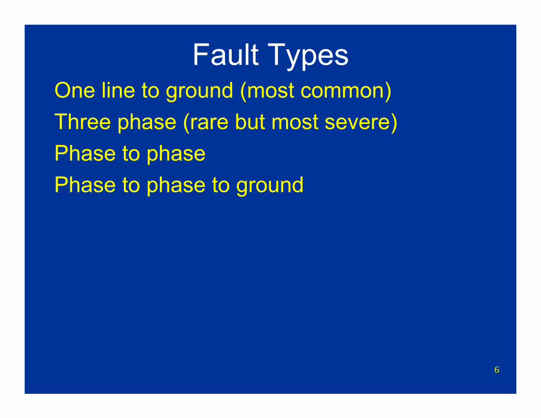
Fault TypesOne line to ground (most common)Three phase (rare but most severe)Phase to phasePhase to phase to ground
7
Symmetrical Components
8
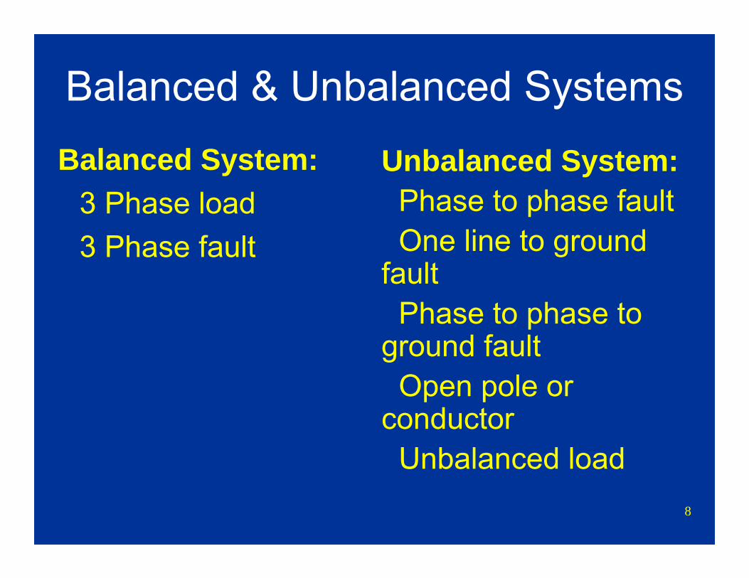
Balanced & Unbalanced Systems
Balanced System:3 Phase load3 Phase fault
Unbalanced System:Phase to phase faultOne line to ground
faultPhase to phase to
ground faultOpen pole or
conductorUnbalanced load

9
Balanced & Unbalanced Systems
A
C
BBalancedSystem
A
C
BUnbalanced System
10
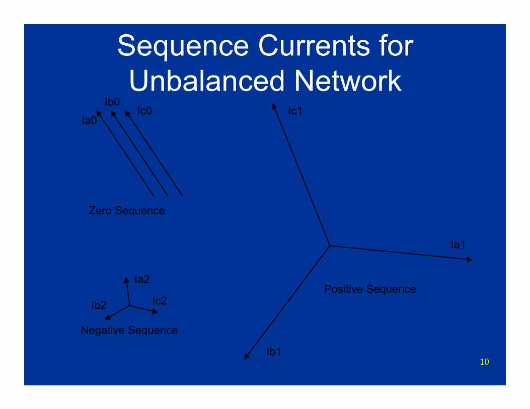
Sequence Currents for Unbalanced Network
Ia2
Ic2Ib2
Negative Sequence
Ic0Ib0
Ia0
Zero Sequence
Ia1
Ic1
Ib1
Positive Sequence
11
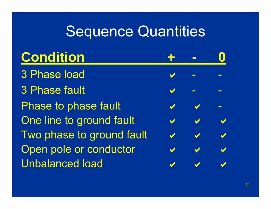
Sequence Quantities
Condition + - 03 Phase load - -3 Phase fault - -Phase to phase fault -One line to ground faultTwo phase to ground faultOpen pole or conductorUnbalanced load
12
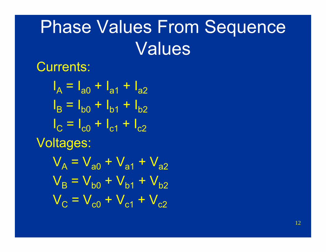
Phase Values From Sequence Values
Currents:IA = Ia0 + Ia1 + Ia2
IB = Ib0 + Ib1 + Ib2
IC = Ic0 + Ic1 + Ic2
Voltages:VA = Va0 + Va1 + Va2
VB = Vb0 + Vb1 + Vb2
VC = Vc0 + Vc1 + Vc2
13
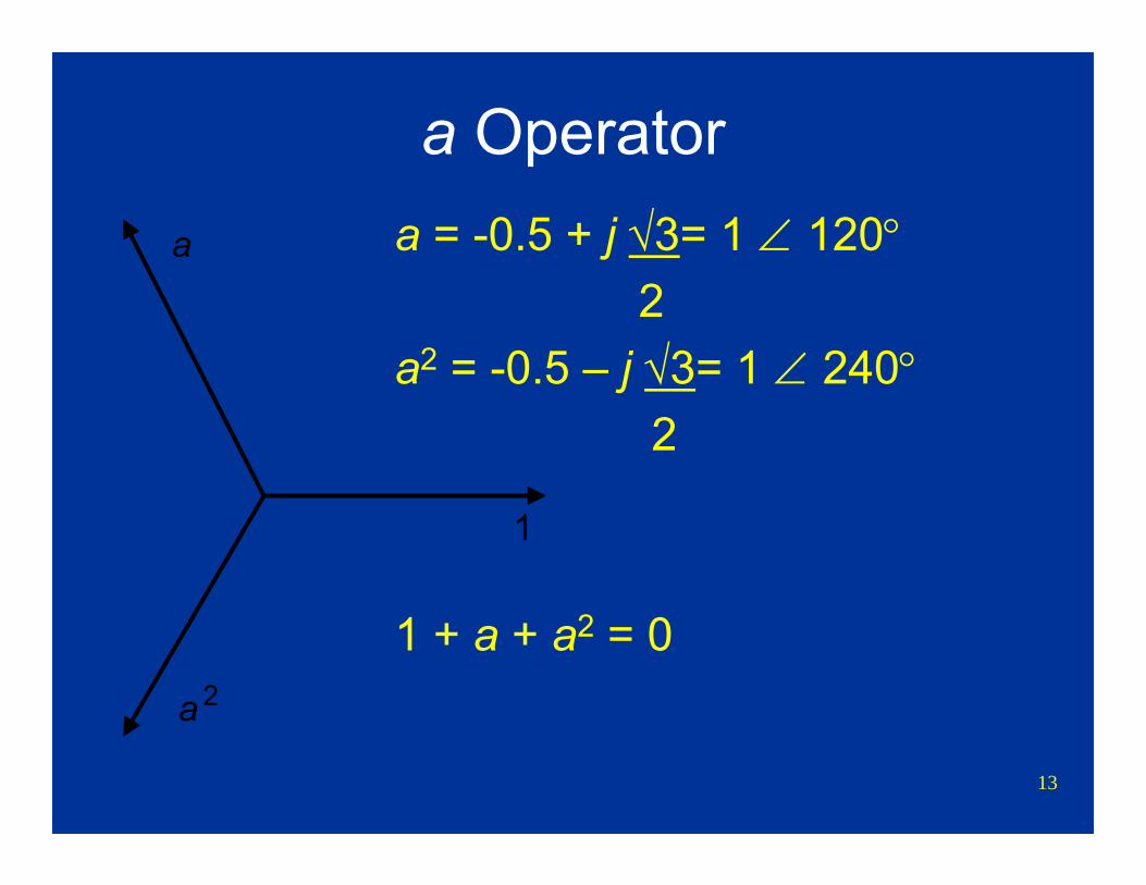
a Operatora = -0.5 + j √3= 1 ∠ 120°
2a2 = -0.5 – j √3= 1 ∠ 240°
2
1 + a + a2 = 0
1
a
a 2
14
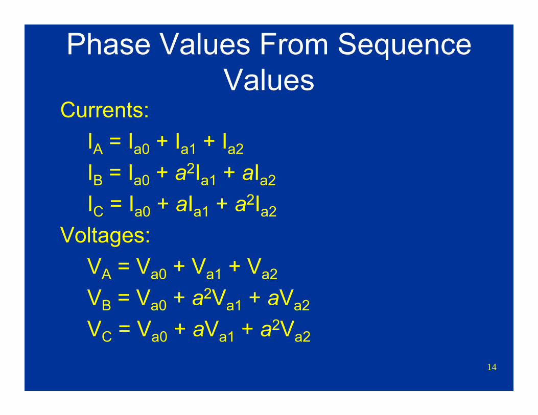
Phase Values From Sequence Values
Currents:IA = Ia0 + Ia1 + Ia2
IB = Ia0 + a2Ia1 + aIa2
IC = Ia0 + aIa1 + a2Ia2
Voltages:VA = Va0 + Va1 + Va2
VB = Va0 + a2Va1 + aVa2
VC = Va0 + aVa1 + a2Va2
15
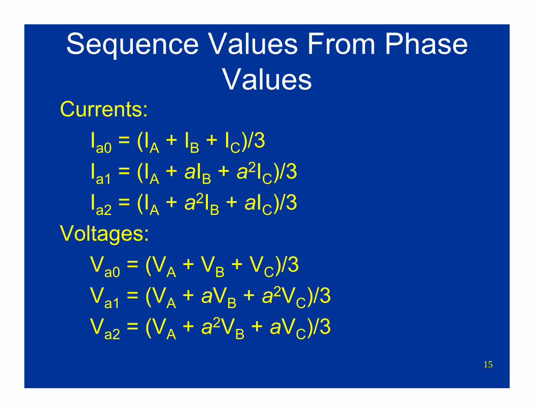
Sequence Values From Phase Values
Currents:Ia0 = (IA + IB + IC)/3Ia1 = (IA + aIB + a2IC)/3Ia2 = (IA + a2IB + aIC)/3
Voltages:Va0 = (VA + VB + VC)/3Va1 = (VA + aVB + a2VC)/3Va2 = (VA + a2VB + aVC)/3
16
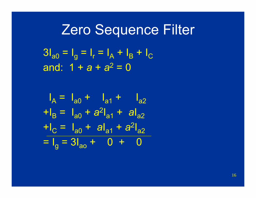
Zero Sequence Filter3Ia0 = Ig = Ir = IA + IB + ICand: 1 + a + a2 = 0
IA = Ia0 + Ia1 + Ia2
+IB = Ia0 + a2Ia1 + aIa2
+IC = Ia0 + aIa1 + a2Ia2
= Ig = 3Iao + 0 + 0
17
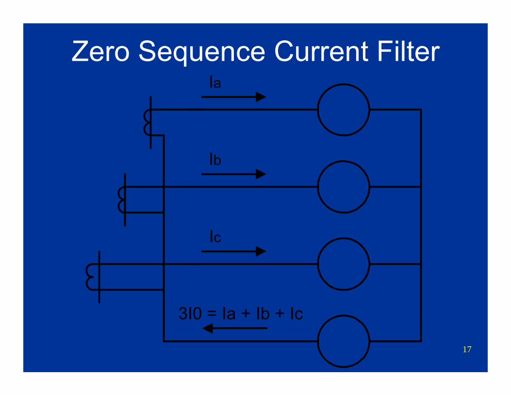
Ia
Ic
Ib
3I0 = Ia + Ib + Ic
Zero Sequence Current Filter
18
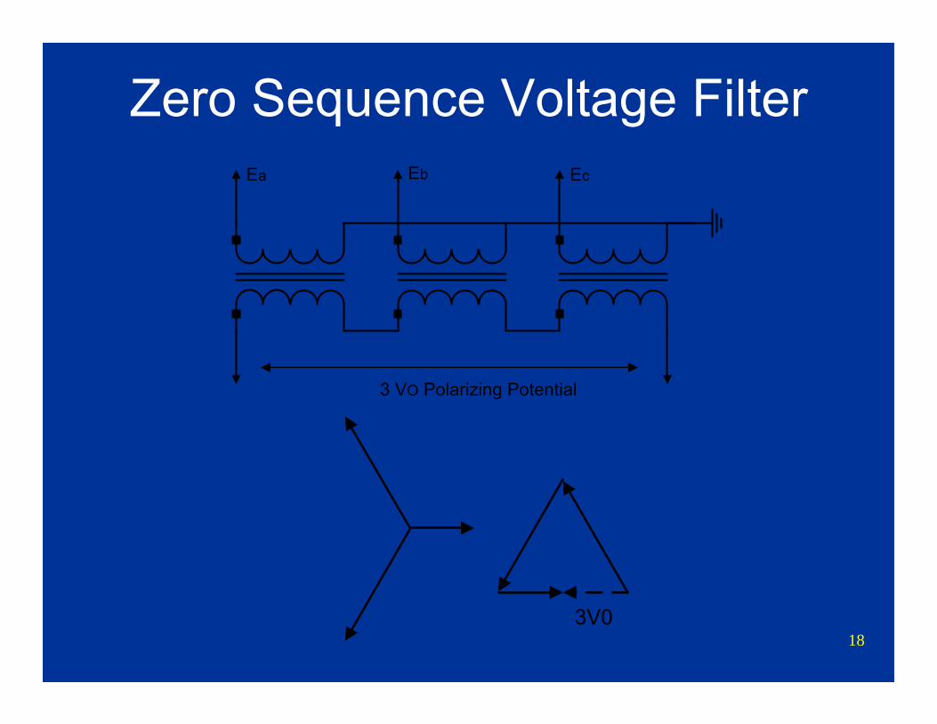
Zero Sequence Voltage Filter
3V0
3 VO Polarizing Potential
Ea Eb Ec
19
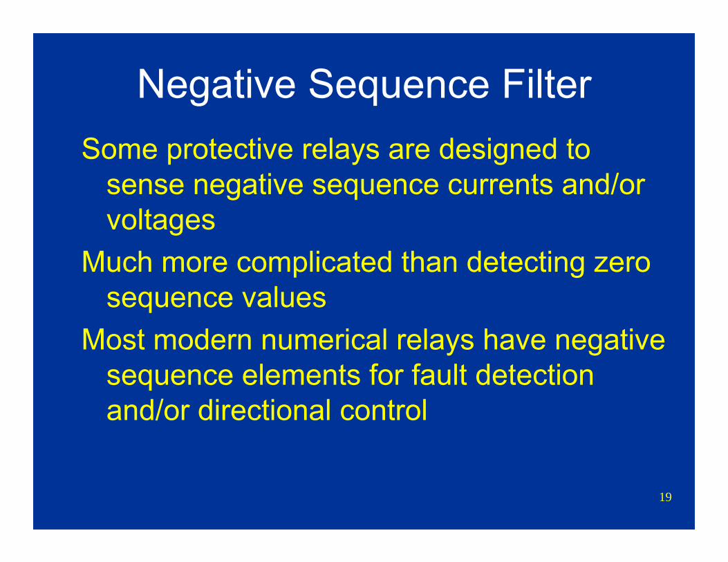
Negative Sequence FilterSome protective relays are designed to
sense negative sequence currents and/or voltages
Much more complicated than detecting zero sequence values
Most modern numerical relays have negative sequence elements for fault detection and/or directional control
20
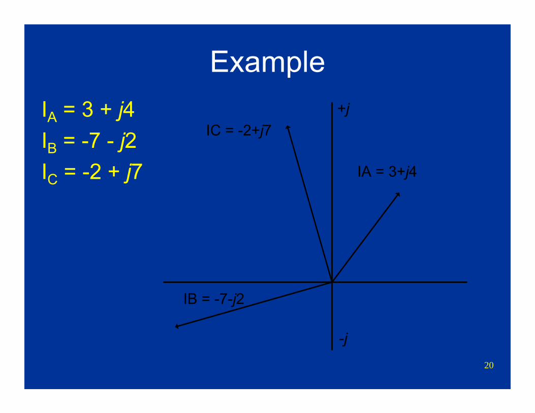
ExampleIA = 3 + j4IB = -7 - j2IC = -2 + j7
+j
-j
IA = 3+j4
IB = -7-j2
IC = -2+j7

21
Zero SequenceIa0 = (IA + IB + IC)/3= [(3+j4)+(-7-j2)+(-2+j7)]/3= -2 + j3 = 3.61 ∠ 124°
Ia0 = Ib0 = Ic0
Ic0Ib0
Ia0
Zero Sequence
22
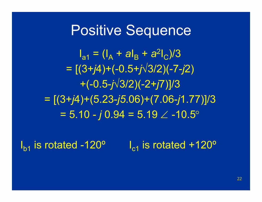
Positive SequenceIa1 = (IA + aIB + a2IC)/3
= [(3+j4)+(-0.5+j√3/2)(-7-j2)+(-0.5-j√3/2)(-2+j7)]/3
= [(3+j4)+(5.23-j5.06)+(7.06-j1.77)]/3= 5.10 - j 0.94 = 5.19 ∠ -10.5°
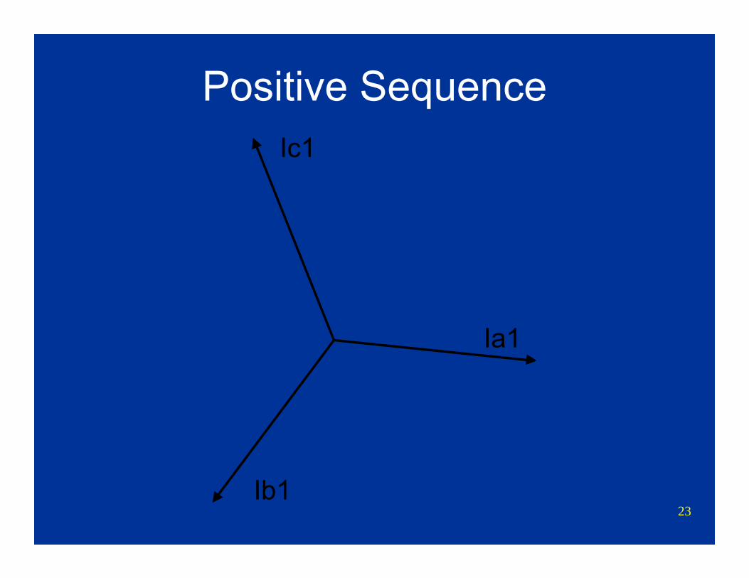
Ib1 is rotated -120º Ic1 is rotated +120º
23
Positive Sequence
Ia1
Ic1
Ib1
24
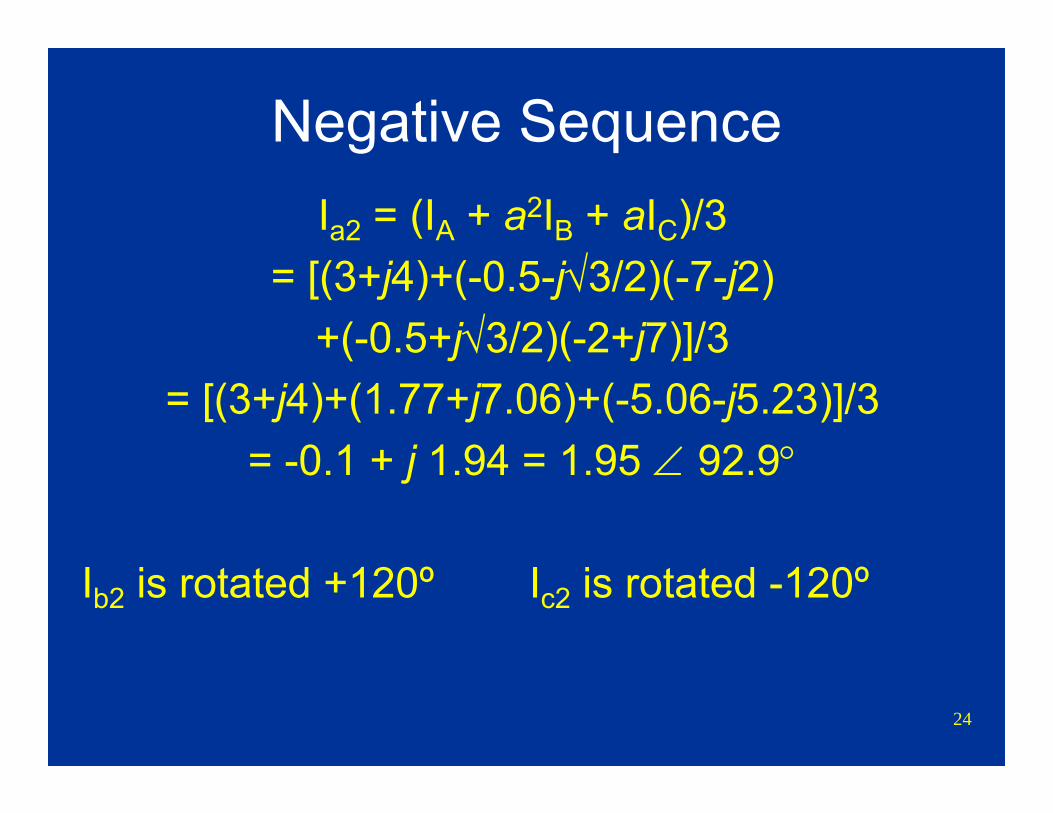
Negative SequenceIa2 = (IA + a2IB + aIC)/3
= [(3+j4)+(-0.5-j√3/2)(-7-j2)+(-0.5+j√3/2)(-2+j7)]/3
= [(3+j4)+(1.77+j7.06)+(-5.06-j5.23)]/3= -0.1 + j 1.94 = 1.95 ∠ 92.9°
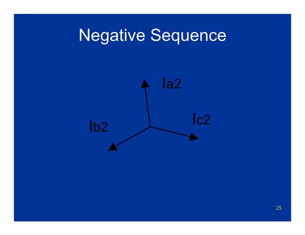
Ib2 is rotated +120º Ic2 is rotated -120º
25
Negative Sequence
Ia2
Ic2Ib2
26
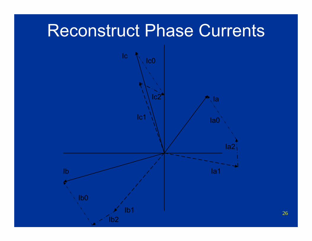
Reconstruct Phase Currents
Ia
Ic
Ib
Ic1
Ib1
Ia1
Ib0
Ia0
Ic0
Ia2
Ib2
Ic2
27
Positive, Negative, and Zero Sequence Impedance
Network Calculations for a Fault Study
28
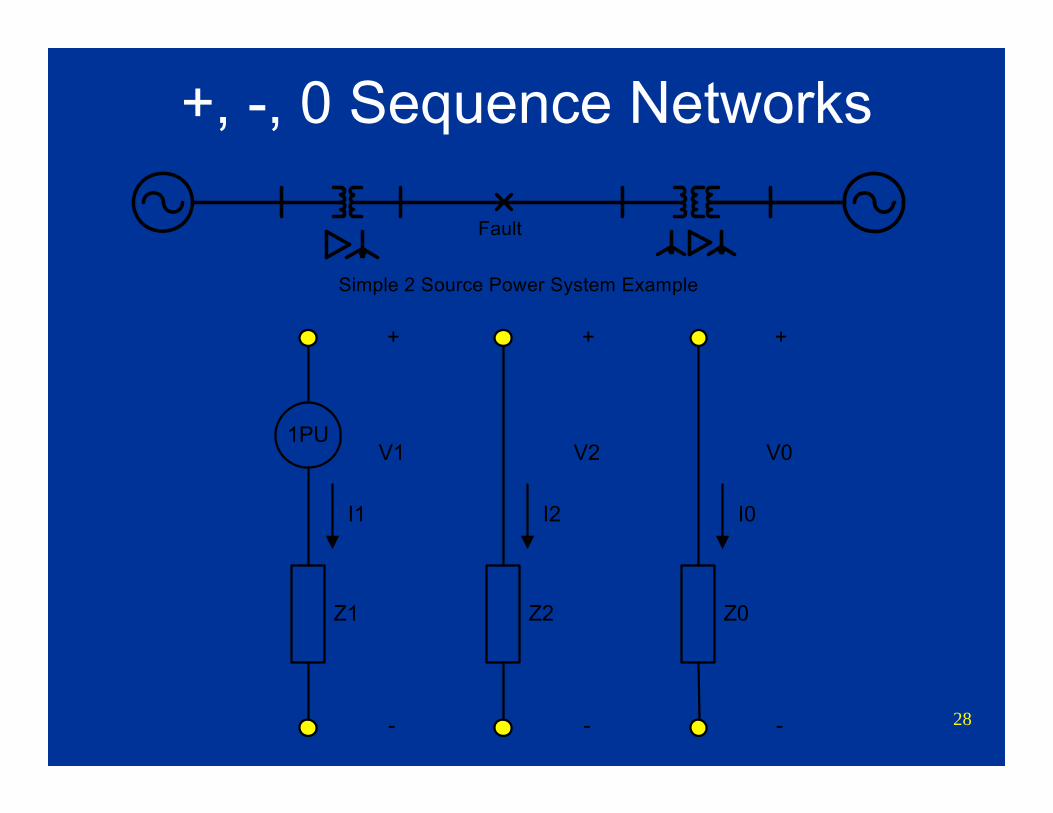
+, -, 0 Sequence Networks
Simple 2 Source Power System Example
Fault
1PU
Z1
I1
Z2
I2
Z0
I0
V0
-
+
V2
-
+
V1
-
+
29
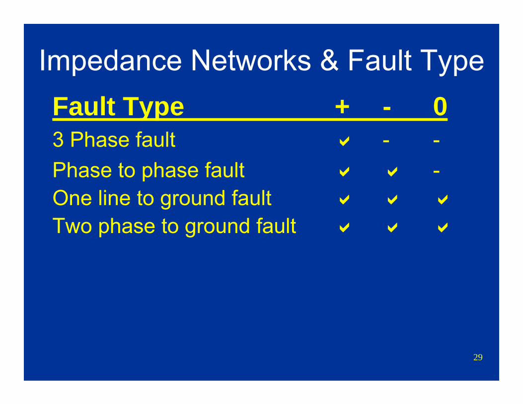
Impedance Networks & Fault TypeFault Type + - 03 Phase fault - -Phase to phase fault -One line to ground faultTwo phase to ground fault
30
Per Unit
31
Per UnitPer unit values are commonly used for fault
calculations and fault study programsPer unit values convert real quantities to
values based upon number 1Per unit values include voltages, currents and
impedances Calculations are easier
Ignore voltage changes due to transformers Ohms law still works
32
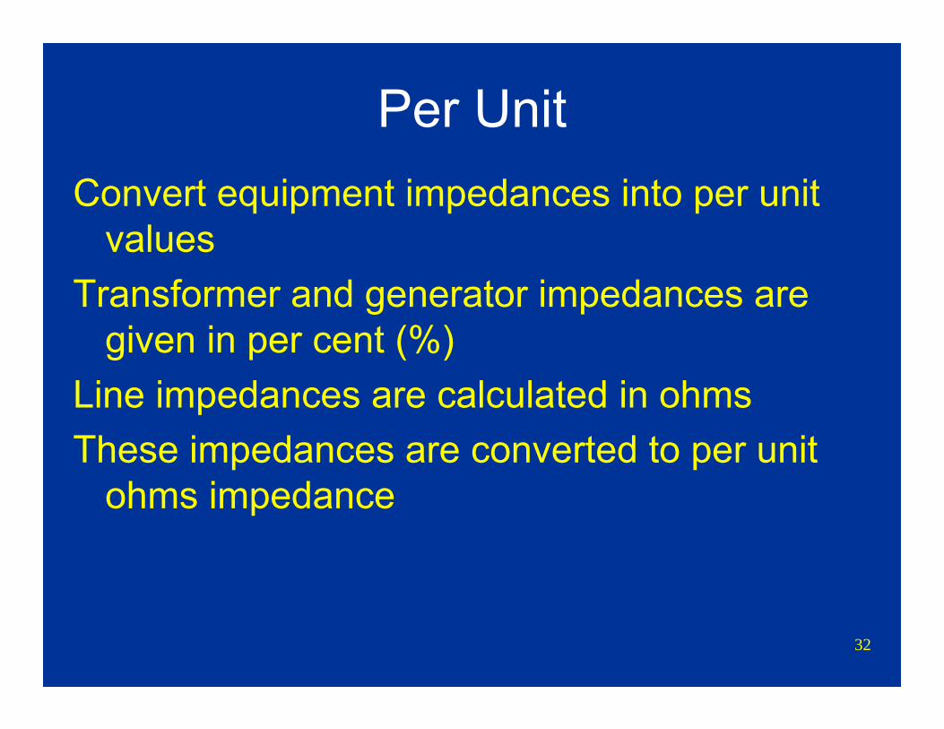
Per UnitConvert equipment impedances into per unit
valuesTransformer and generator impedances are
given in per cent (%)Line impedances are calculated in ohmsThese impedances are converted to per unit
ohms impedance
33
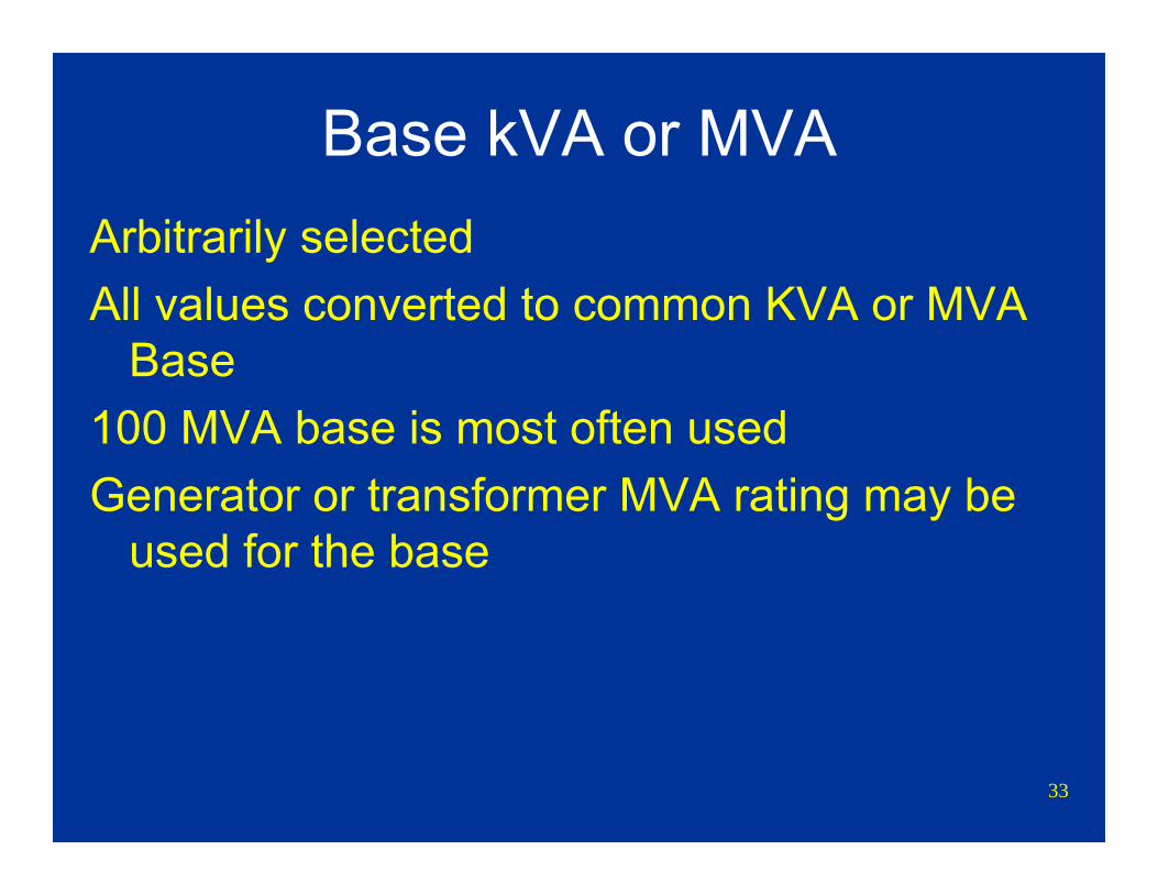
Base kVA or MVAArbitrarily selectedAll values converted to common KVA or MVA
Base100 MVA base is most often usedGenerator or transformer MVA rating may be
used for the base
34
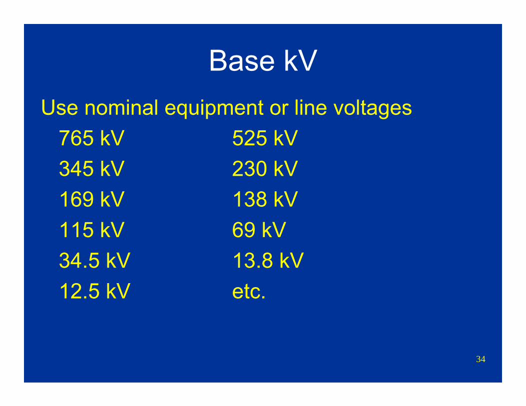
Base kVUse nominal equipment or line voltages
765 kV 525 kV345 kV 230 kV169 kV 138 kV115 kV 69 kV34.5 kV 13.8 kV12.5 kV etc.
35
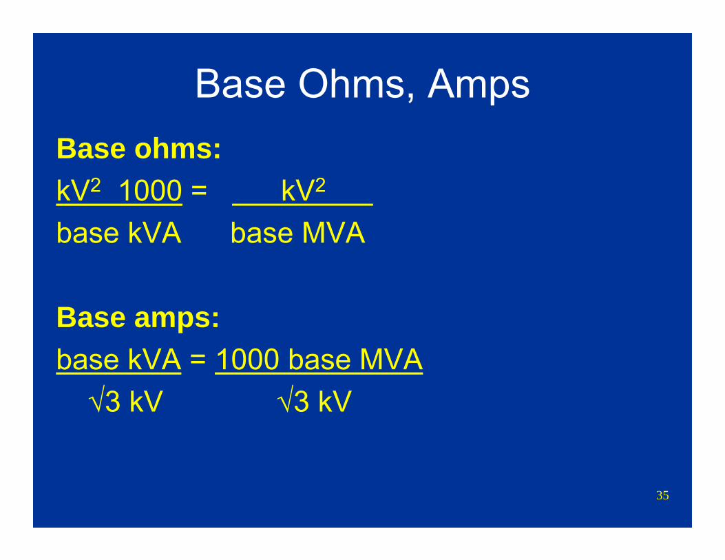
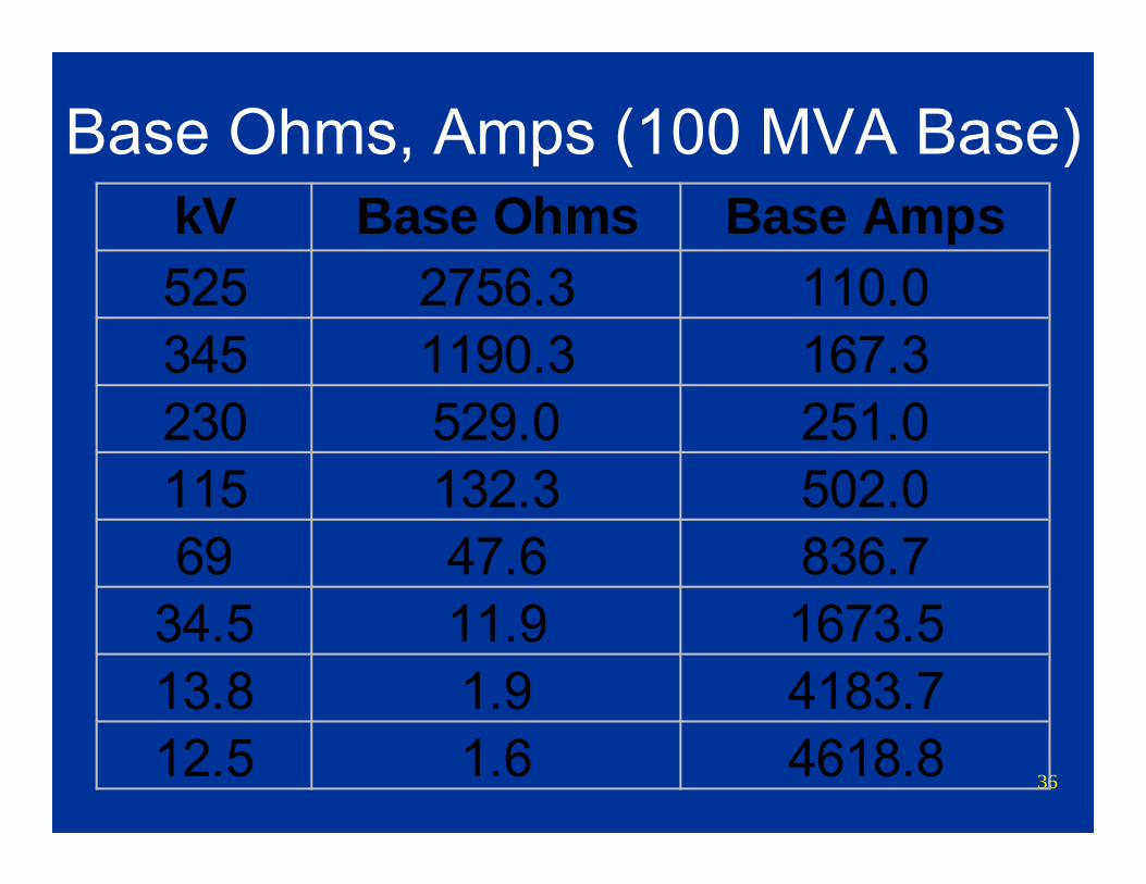
Base Ohms, AmpsBase ohms:kV2 1000 = kV2 base kVA base MVA
Base amps:base kVA = 1000 base MVA
√3 kV √3 kV
36
Base Ohms, Amps (100 MVA Base)kV Base Ohms Base Amps525 2756.3 110.0345 1190.3 167.3230 529.0 251.0115 132.3 502.069 47.6 836.7
34.5 11.9 1673.513.8 1.9 4183.712.5 1.6 4618.8
37
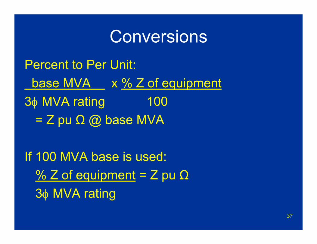
ConversionsPercent to Per Unit:base MVA x % Z of equipment
3φ MVA rating 100= Z pu Ω @ base MVA
If 100 MVA base is used:% Z of equipment = Z pu Ω3φ MVA rating
38
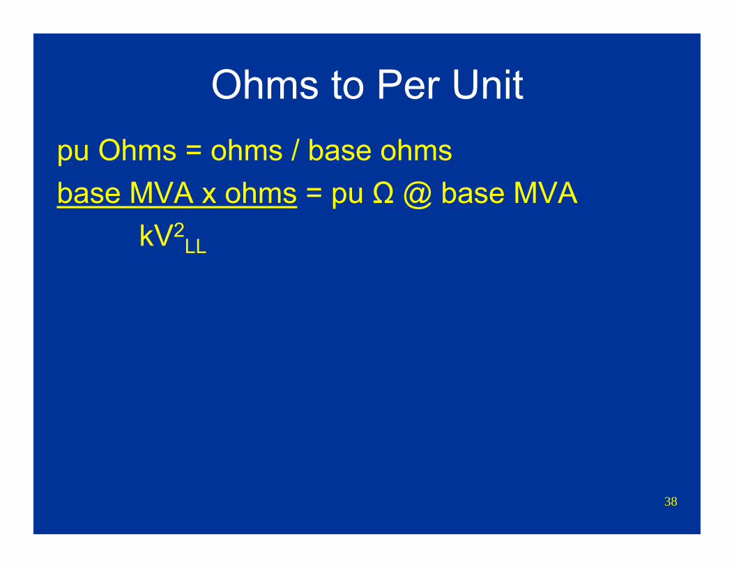
Ohms to Per Unitpu Ohms = ohms / base ohmsbase MVA x ohms = pu Ω @ base MVA
kV2LL

39
Per Unit to Real StuffAmps = pu amps x base amps
kV = pu kV x base kVOhms = pu ohms x base ohms
40
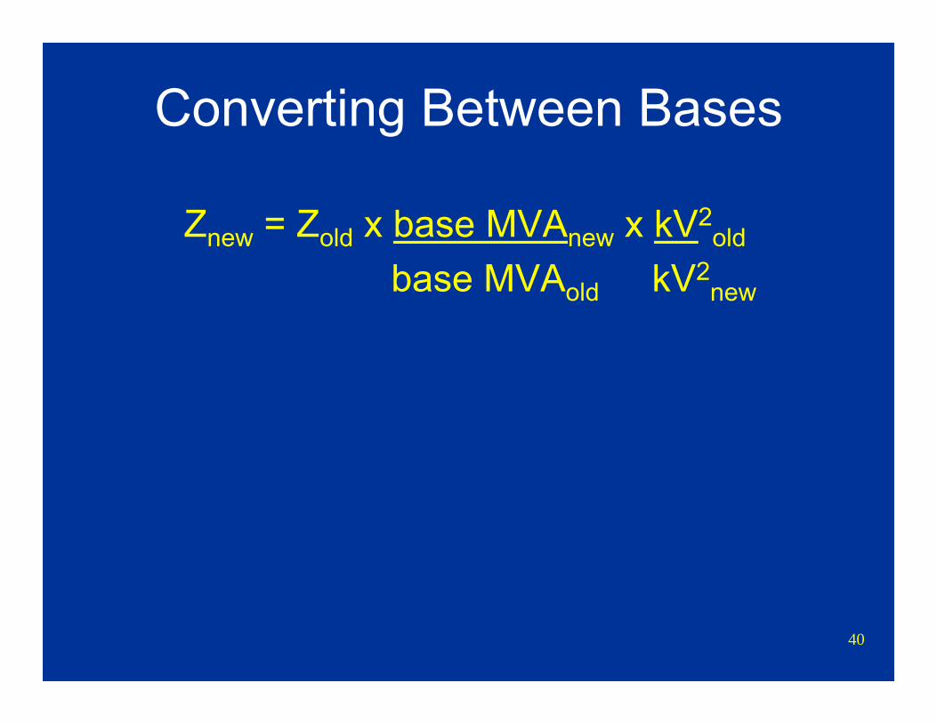
Converting Between Bases
Znew = Zold x base MVAnew x kV2old
base MVAold kV2new
41
Evaluation of System Components
Determine positive, negative, and zero sequence impedances of various devices (Z1, Z2, Z0)
Only machines will act as a voltage source in the positive sequence network
Connect the various impedances into networks according to topography of the system
Connect impedance networks for various fault types or other system conditions
42
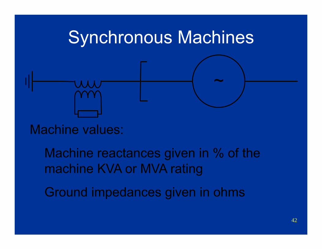
Synchronous Machines
~
Machine values:
Machine reactances given in % of the machine KVA or MVA rating
Ground impedances given in ohms
43
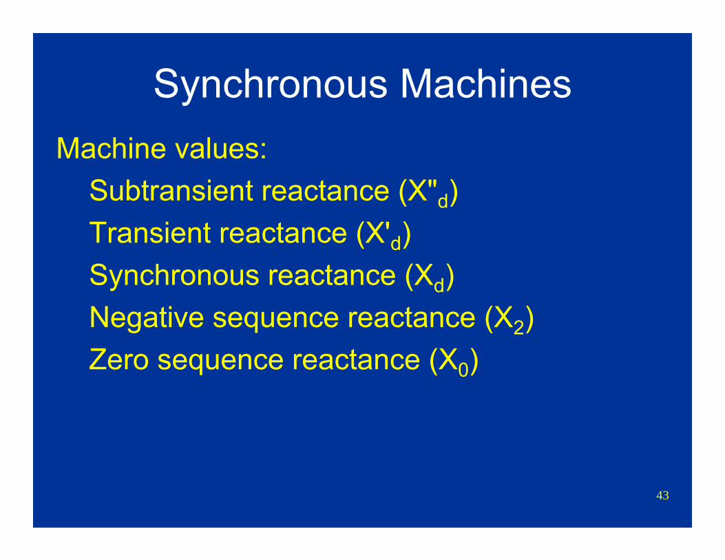
Synchronous MachinesMachine values:
Subtransient reactance (X"d) Transient reactance (X'd) Synchronous reactance (Xd) Negative sequence reactance (X2)Zero sequence reactance (X0)
44
Synchronous MachinesMachine neutral ground impedance: Usually
expressed in ohmsUse 3R or 3X for fault calculations
Calculations generally ignores resistance values for generators
Calculations generally uses X”d for all impedance values
45
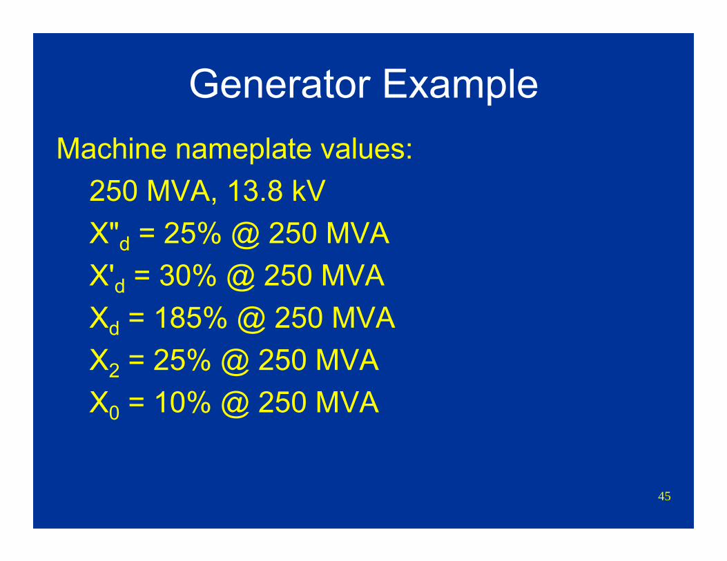
Generator ExampleMachine nameplate values:
250 MVA, 13.8 kVX"d = 25% @ 250 MVAX'd = 30% @ 250 MVAXd = 185% @ 250 MVAX2 = 25% @ 250 MVAX0 = 10% @ 250 MVA
46
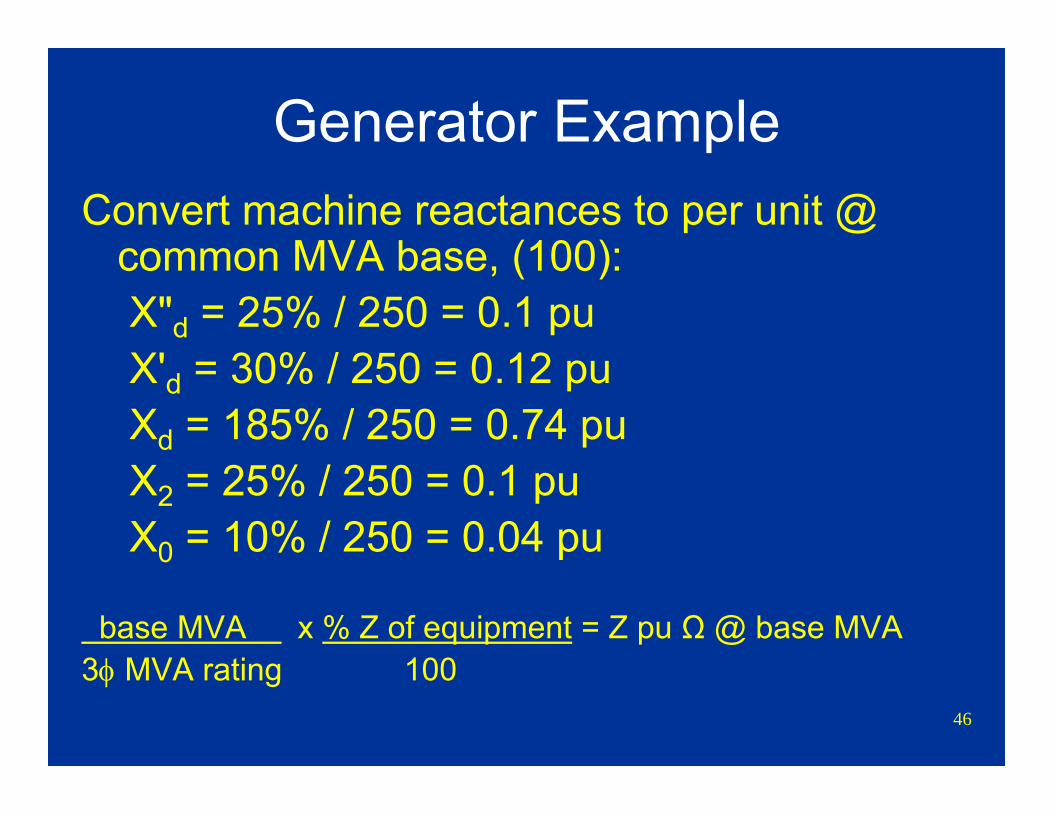
Generator ExampleConvert machine reactances to per unit @
common MVA base, (100):X"d = 25% / 250 = 0.1 puX'd = 30% / 250 = 0.12 puXd = 185% / 250 = 0.74 puX2 = 25% / 250 = 0.1 puX0 = 10% / 250 = 0.04 pu
base MVA x % Z of equipment = Z pu Ω @ base MVA3φ MVA rating 100
47
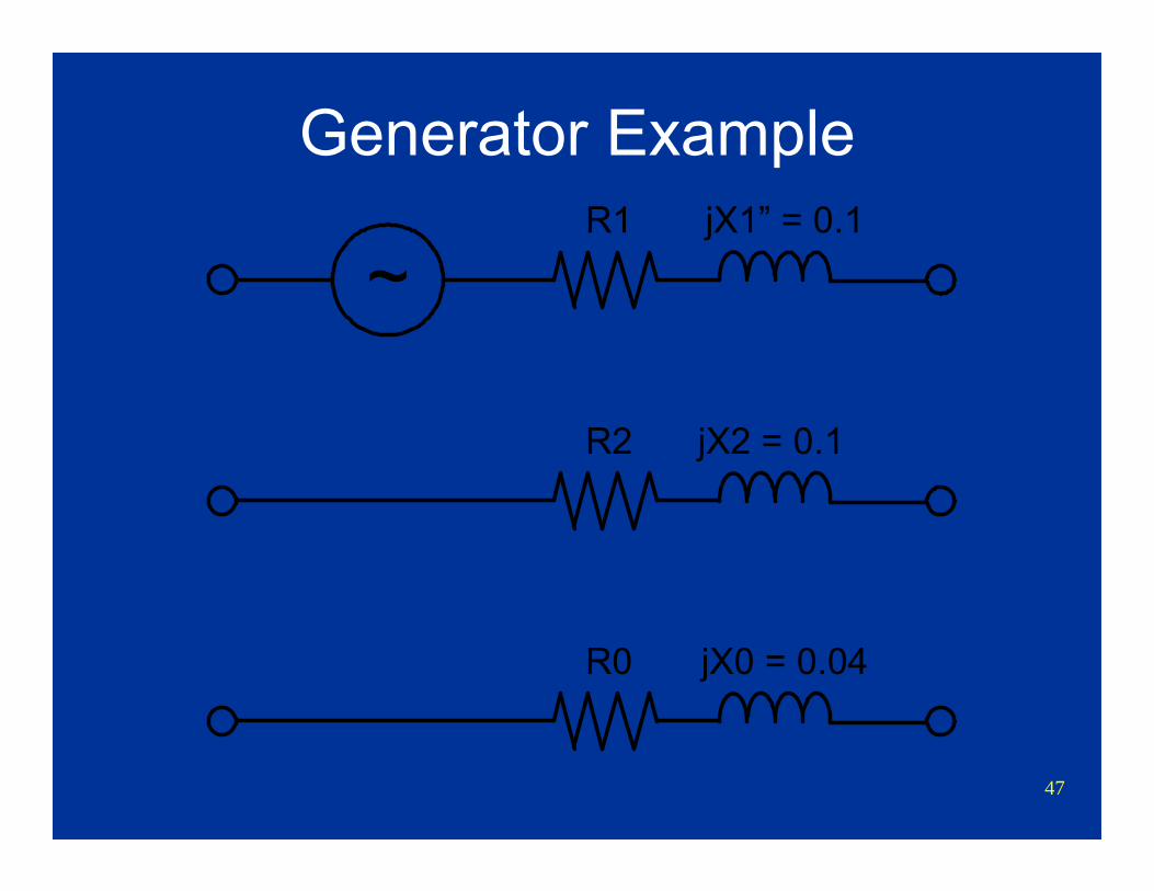
Generator Example
~R1 jX1” = 0.1
R0 jX0 = 0.04
R2 jX2 = 0.1
48
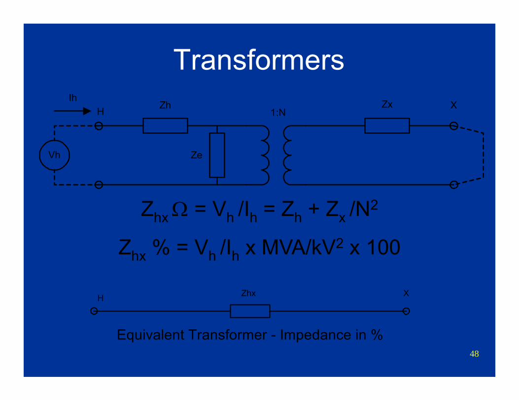
TransformersZx X
Ze
ZhH 1:N
Vh
Ih
ZhxH X
Equivalent Transformer - Impedance in %
Zhx Ω = Vh /Ih = Zh + Zx /N2
Zhx % = Vh /Ih x MVA/kV2 x 100
49
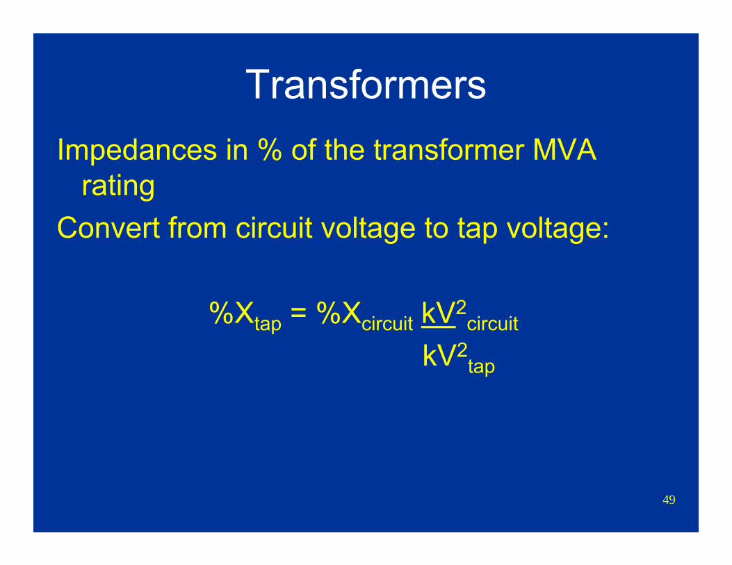
TransformersImpedances in % of the transformer MVA
ratingConvert from circuit voltage to tap voltage:
%Xtap = %Xcircuit kV2circuit
kV2tap
50
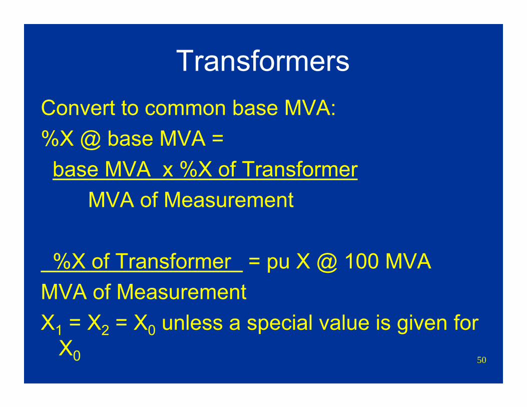
TransformersConvert to common base MVA:%X @ base MVA =base MVA x %X of Transformer
MVA of Measurement
%X of Transformer = pu X @ 100 MVAMVA of MeasurementX1 = X2 = X0 unless a special value is given for
X0
51
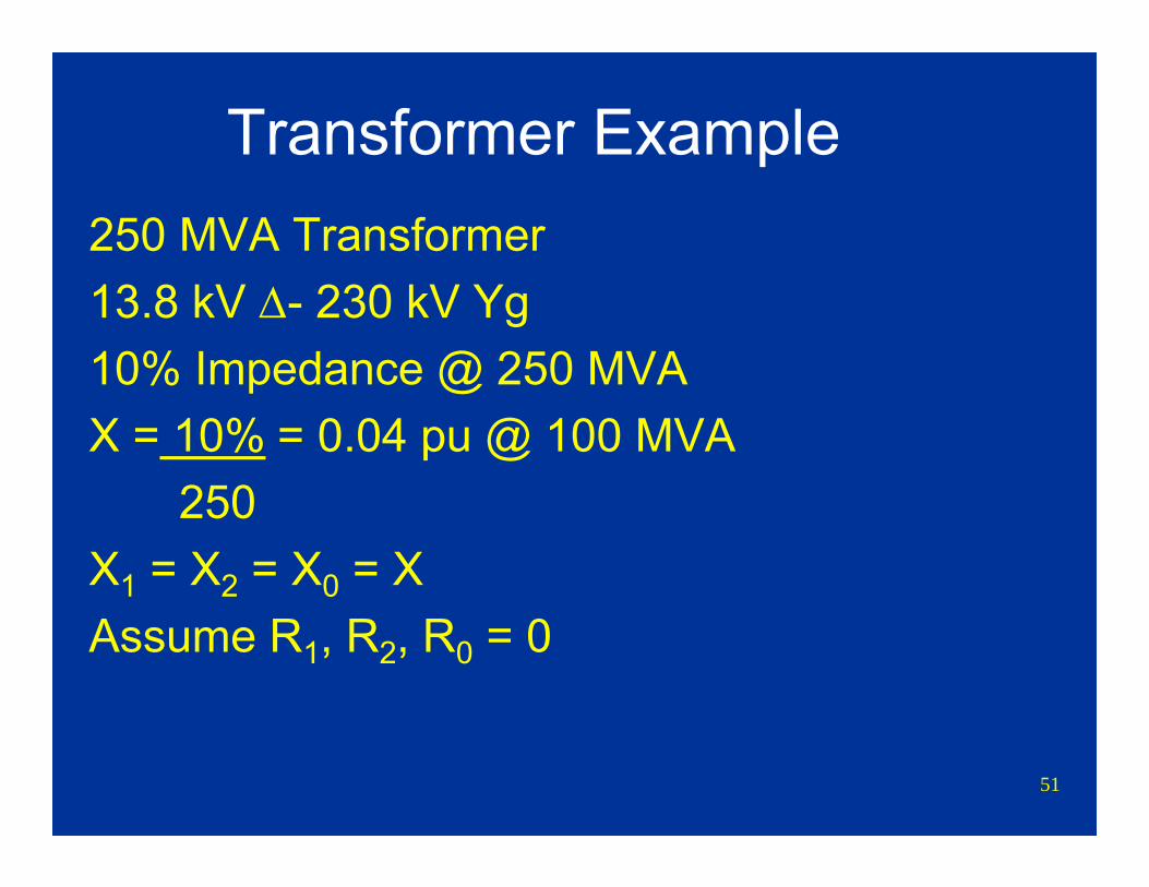
Transformer Example250 MVA Transformer13.8 kV Δ- 230 kV Yg10% Impedance @ 250 MVAX = 10% = 0.04 pu @ 100 MVA
250X1 = X2 = X0 = XAssume R1, R2, R0 = 0

52
Transformer ExampleR1 jX1 = 0.04
R0 jX0 = 0.04
R2 jX2 = 0.04
Zero sequence connection depends upon winding configuration.
53
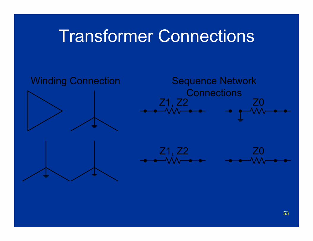
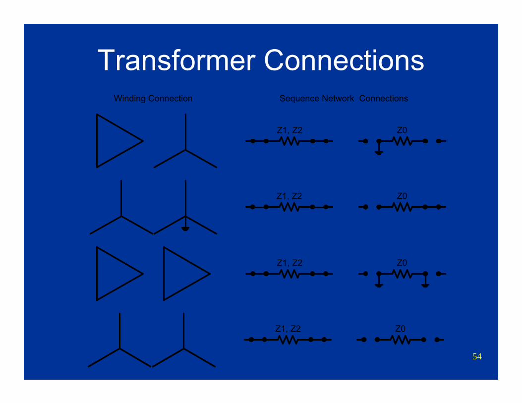
Transformer Connections
Winding Connection Sequence NetworkConnections
Z1, Z2 Z0
Z1, Z2 Z0
54
Transformer ConnectionsWinding Connection Sequence Network Connections
Z1, Z2 Z0
Z1, Z2 Z0
Z1, Z2 Z0
Z1, Z2 Z0
55
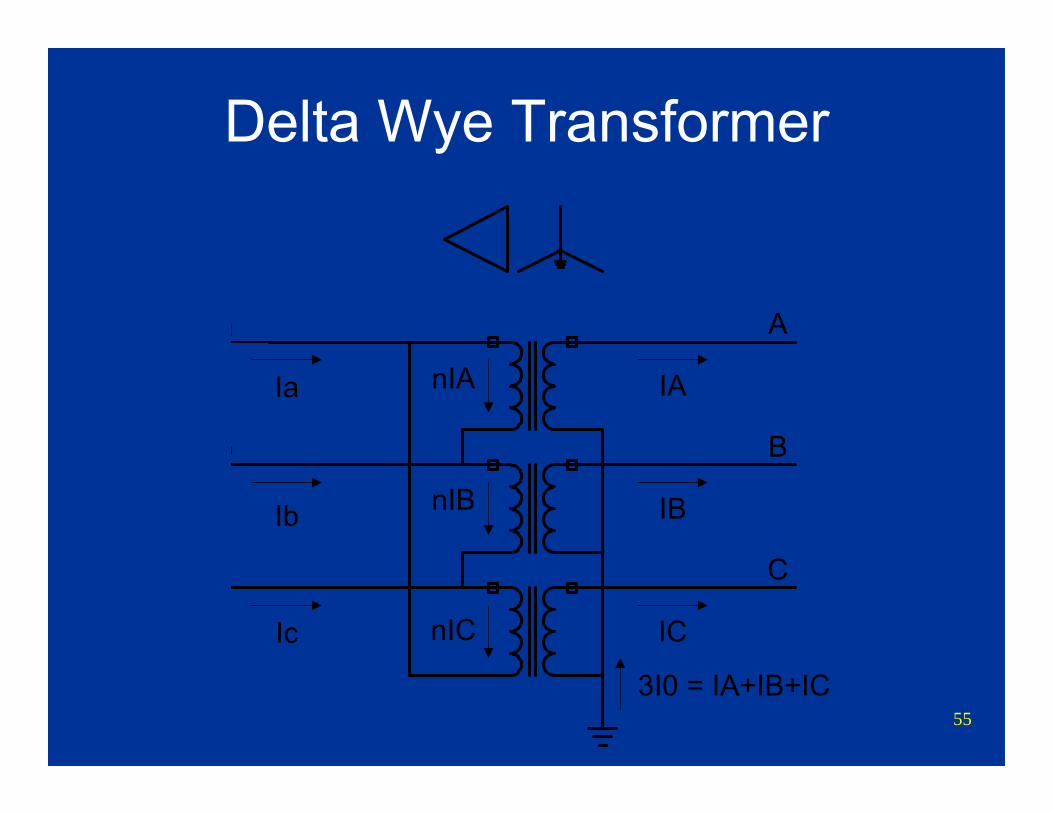
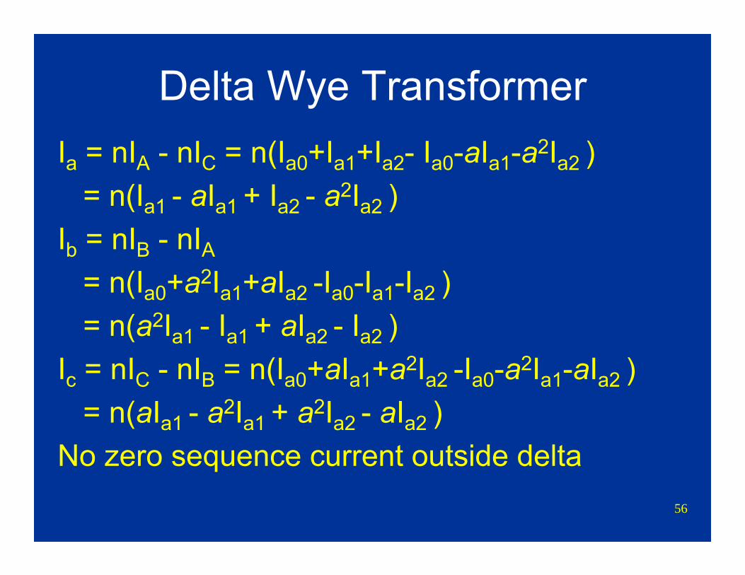
Delta Wye Transformer
A
B
C
b
a
Ia
Ic
Ib
IA
IB
IC
nIA
nIC
3I0 = IA+IB+IC
nIB
56
Delta Wye TransformerIa = nIA - nIC = n(Ia0+Ia1+Ia2- Ia0-aIa1-a2Ia2 )
= n(Ia1 - aIa1 + Ia2 - a2Ia2 )Ib = nIB - nIA
= n(Ia0+a2Ia1+aIa2 -Ia0-Ia1-Ia2 )= n(a2Ia1 - Ia1 + aIa2 - Ia2 )
Ic = nIC - nIB = n(Ia0+aIa1+a2Ia2 -Ia0-a2Ia1-aIa2 )= n(aIa1 - a2Ia1 + a2Ia2 - aIa2 )
No zero sequence current outside delta
57
Transformer ConnectionsA YG / YG connection provides a series
connection for zero sequence currentA Δ / YG connection provides a zero sequence
(I0) current source for the YG windingAuto transformer provides same connection as
YG / YG connectionUse 3R or 3X if a Y is connected to ground
with a resistor or reactor

58
Three Winding TransformerImpedances ZHL, ZHM, & ZML given in % at
corresponding winding ratingConvert impedances to common base MVACalculate corresponding “T” network
impedances:ZH = (ZHL+ ZHM - ZML)/2
ZM = (- ZHL+ ZHM + ZML)/2 ZL = (ZHL- ZHM + ZML)/2
59
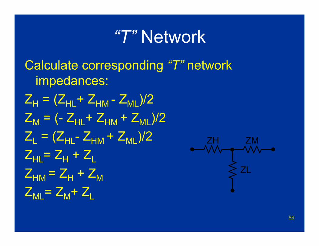
“T” NetworkCalculate corresponding “T” network
impedances:ZH = (ZHL+ ZHM - ZML)/2 ZM = (- ZHL+ ZHM + ZML)/2 ZL = (ZHL- ZHM + ZML)/2 ZHL= ZH + ZL
ZHM = ZH + ZM
ZML= ZM+ ZL
ZH ZM
ZL
60
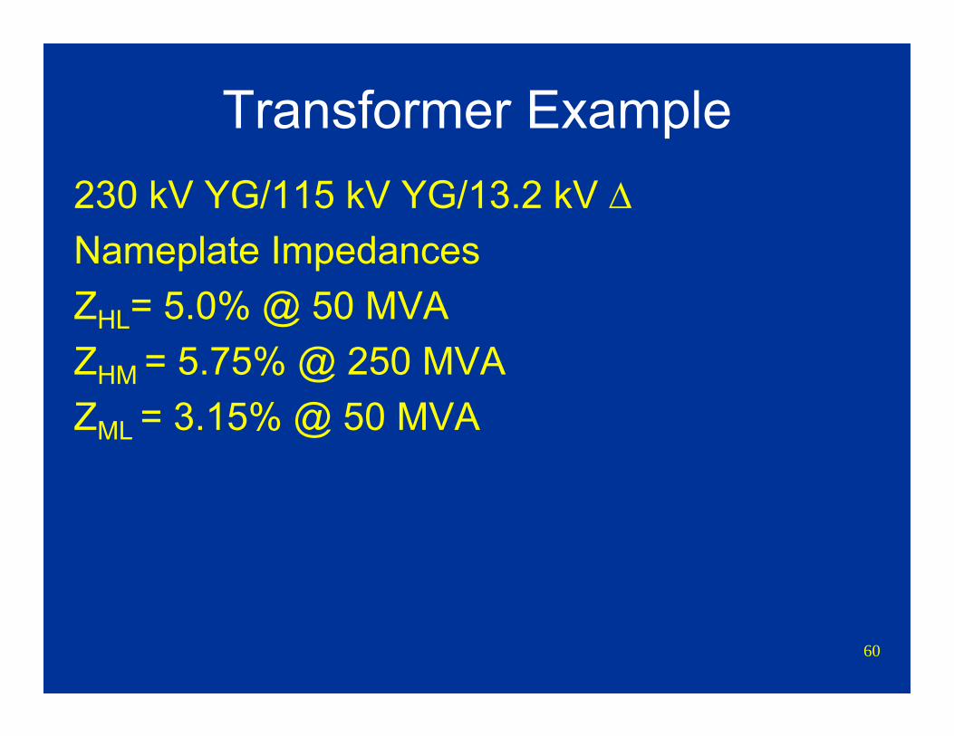
Transformer Example230 kV YG/115 kV YG/13.2 kV ΔNameplate Impedances ZHL= 5.0% @ 50 MVAZHM = 5.75% @ 250 MVAZML = 3.15% @ 50 MVA
61
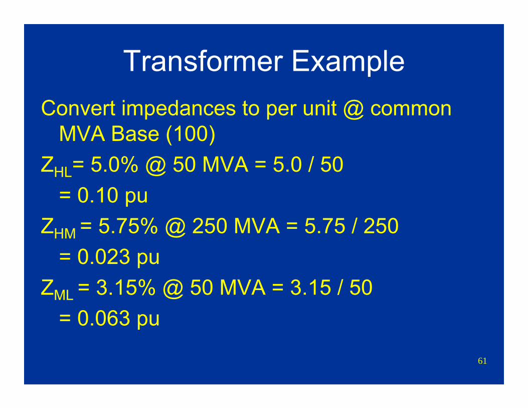
Transformer ExampleConvert impedances to per unit @ common
MVA Base (100)ZHL= 5.0% @ 50 MVA = 5.0 / 50
= 0.10 puZHM = 5.75% @ 250 MVA = 5.75 / 250
= 0.023 puZML = 3.15% @ 50 MVA = 3.15 / 50
= 0.063 pu

62
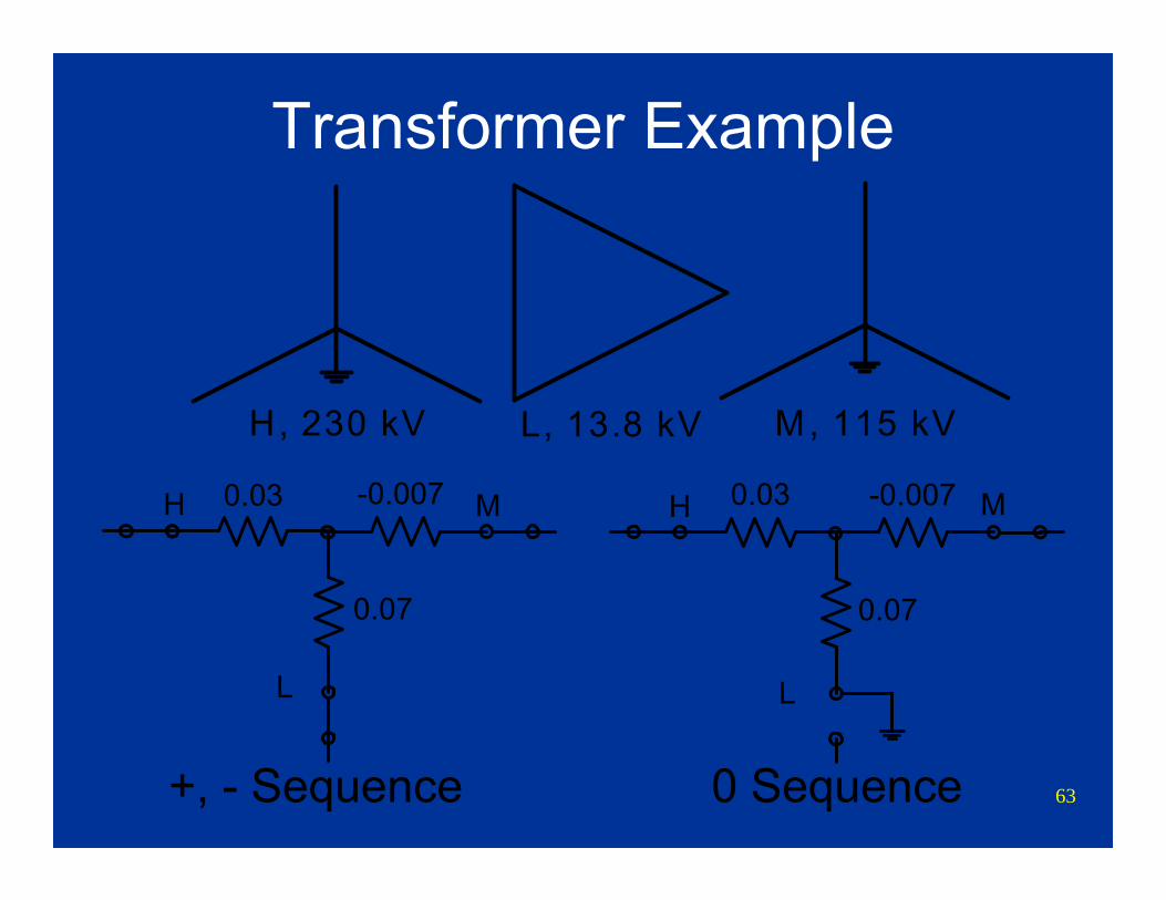
Transformer ExampleConvert impedances to “T” network equivalentZH = (ZHL+ ZHM - ZML)/2
= (0.1 + 0.023 - 0.063)/2 = 0.03 puZM = (- ZHL+ ZHM + ZML)/2
= (-0.1 + 0.023 + 0.063)/2 = - 0.007 puZL = (ZHL- ZHM + ZML)/2
= (0.1 - 0.023 + 0.063)/2 = 0.07 pu
63
Transformer Example
0.03 -0.007
0.07
H M 0.03 -0.007
0.07
H M
LL
H, 230 kV L, 13.8 kV M, 115 kV
+, - Sequence 0 Sequence
Problem
Calculate pu impedances for generators and transformers
Use 100 MVA base Ignore all resistances

65
Problem
Fault
13.8 kV 13.8 kV230 kV230 kV
115 kV
66
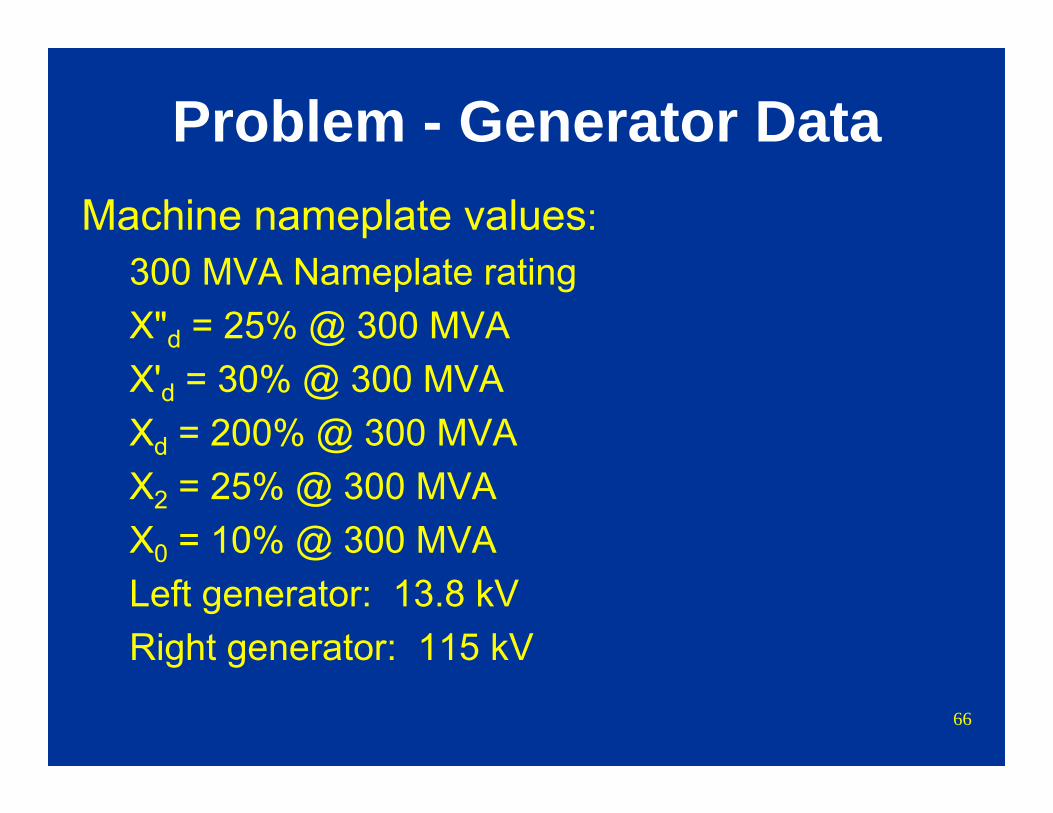
Problem - Generator DataMachine nameplate values:
300 MVA Nameplate rating X"d = 25% @ 300 MVAX'd = 30% @ 300 MVAXd = 200% @ 300 MVAX2 = 25% @ 300 MVAX0 = 10% @ 300 MVALeft generator: 13.8 kVRight generator: 115 kV
67
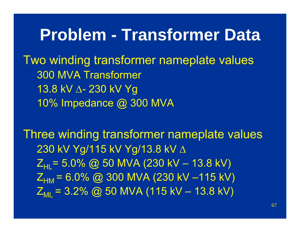
Problem - Transformer DataTwo winding transformer nameplate values
300 MVA Transformer13.8 kV Δ- 230 kV Yg10% Impedance @ 300 MVA
Three winding transformer nameplate values230 kV Yg/115 kV Yg/13.8 kV ΔZHL= 5.0% @ 50 MVA (230 kV – 13.8 kV)ZHM = 6.0% @ 300 MVA (230 kV –115 kV)ZML = 3.2% @ 50 MVA (115 kV – 13.8 kV)
68
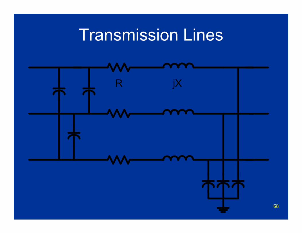
Transmission Lines
R jX
69
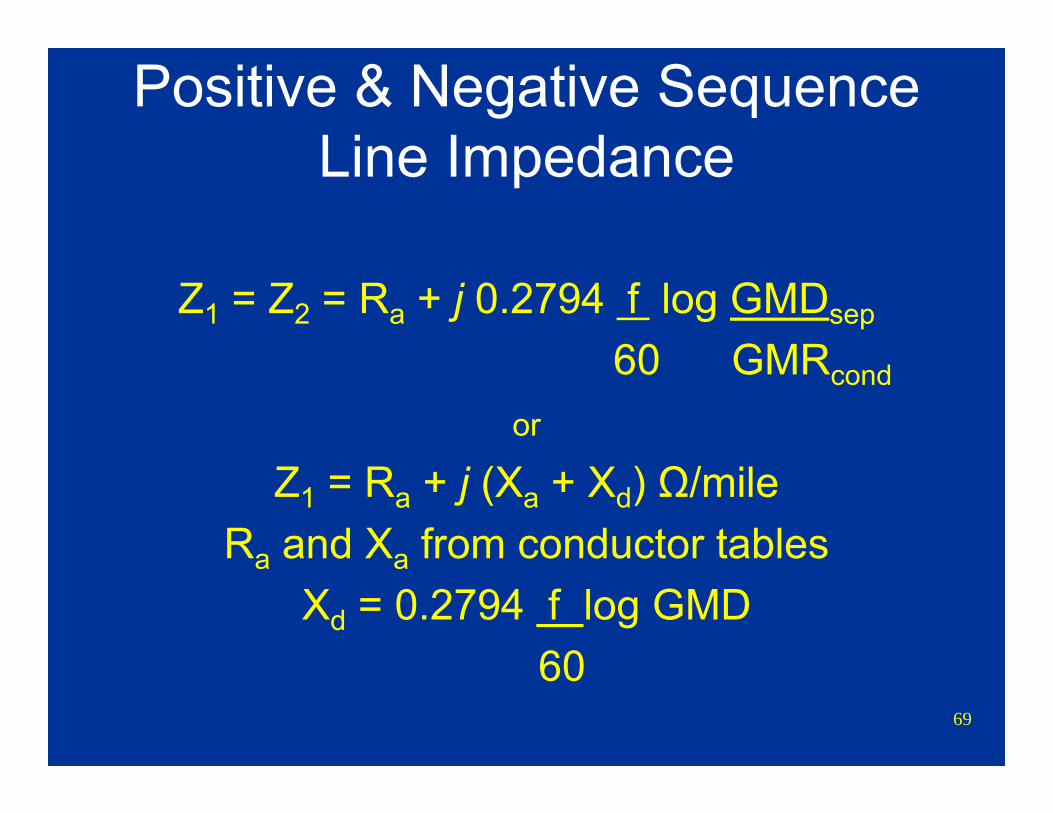
Positive & Negative Sequence Line Impedance
Z1 = Z2 = Ra + j 0.2794 f log GMDsep
60 GMRcond
or
Z1 = Ra + j (Xa + Xd) Ω/mileRa and Xa from conductor tables
Xd = 0.2794 f log GMD60
70
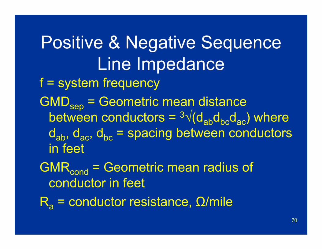
Positive & Negative Sequence Line Impedance
f = system frequencyGMDsep = Geometric mean distance
between conductors = 3√(dabdbcdac) where dab, dac, dbc = spacing between conductors in feet
GMRcond = Geometric mean radius of conductor in feet
Ra = conductor resistance, Ω/mile
71
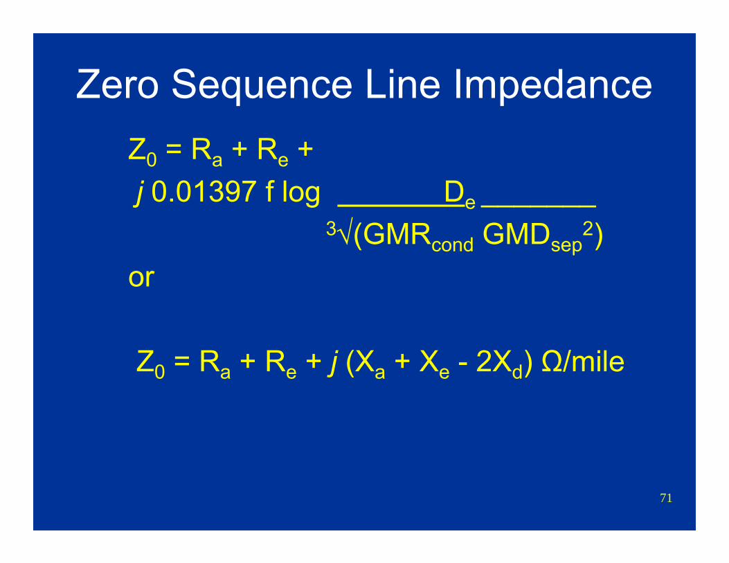
Zero Sequence Line ImpedanceZ0 = Ra + Re +j 0.01397 f log De _______
3√(GMRcond GMDsep2)
or
Z0 = Ra + Re + j (Xa + Xe - 2Xd) Ω/mile
72
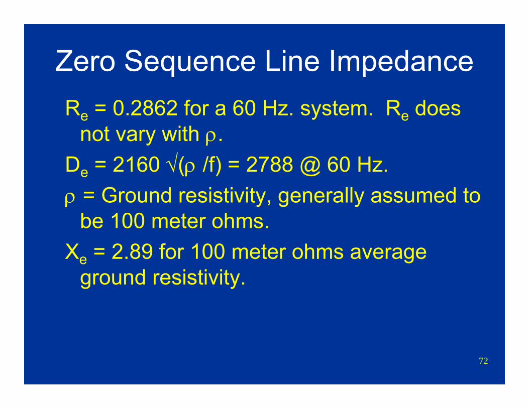
Zero Sequence Line ImpedanceRe = 0.2862 for a 60 Hz. system. Re does
not vary with ρ.De = 2160 √(ρ /f) = 2788 @ 60 Hz.ρ = Ground resistivity, generally assumed to
be 100 meter ohms.Xe = 2.89 for 100 meter ohms average
ground resistivity.
73
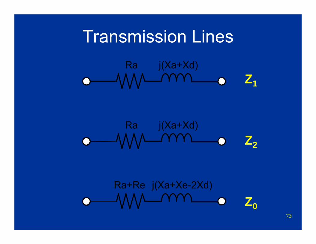
Transmission LinesRa j(Xa+Xd)
Ra+Re j(Xa+Xe-2Xd)
Ra j(Xa+Xd)
Z1
Z2
Z0

74
Transmission Line Example230 kV Line50 Miles long1272 kcmil ACSR Pheasant Conductor
Ra = 0.0903 Ω /mile @ 80° CXa = 0.37201 Ω /mileGMR = 0.0466 feet
Structure: horizontal “H” frame
75
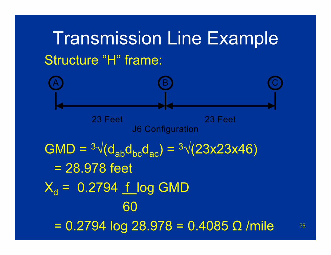
Transmission Line ExampleStructure “H” frame:
GMD = 3√(dabdbcdac) = 3√(23x23x46) = 28.978 feet
Xd = 0.2794 f log GMD60
= 0.2794 log 28.978 = 0.4085 Ω /mile
A CB
23 Feet 23 FeetJ6 Configuration
76
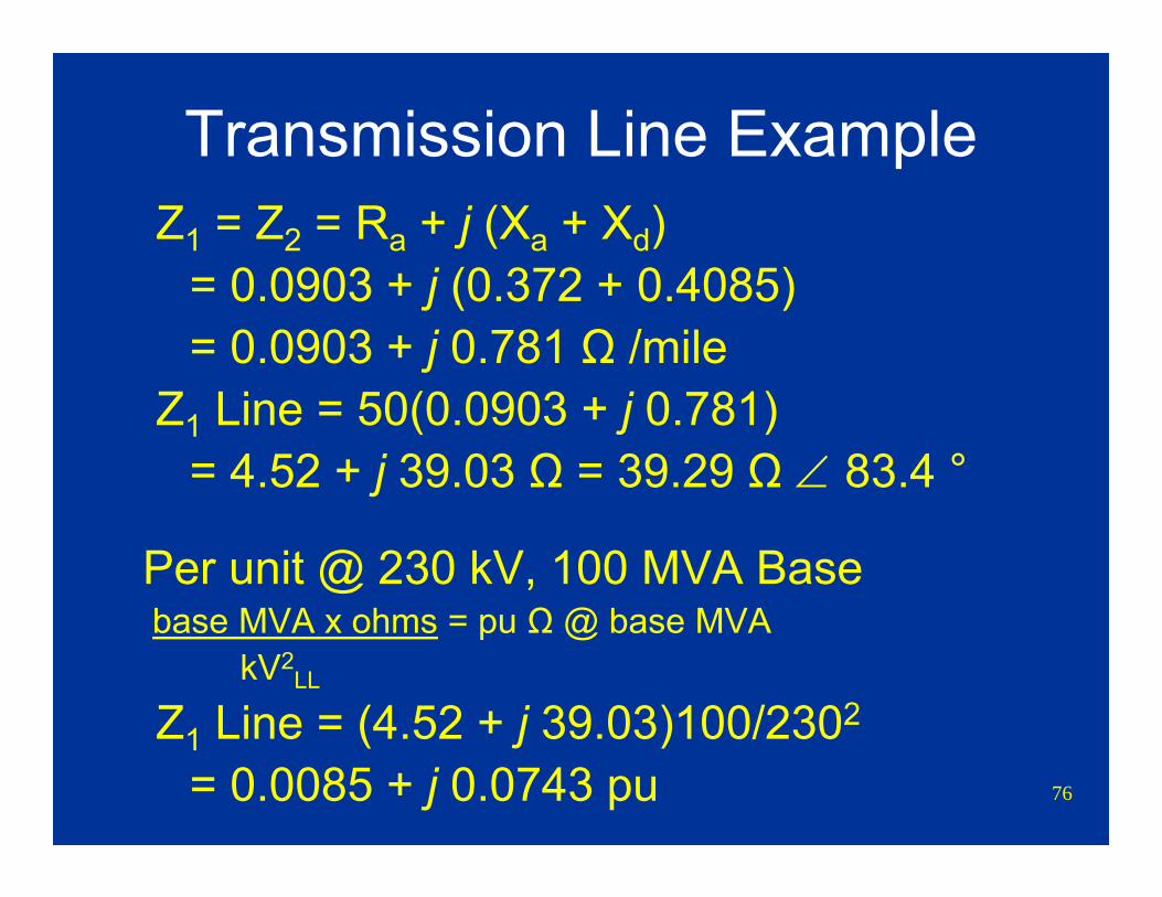
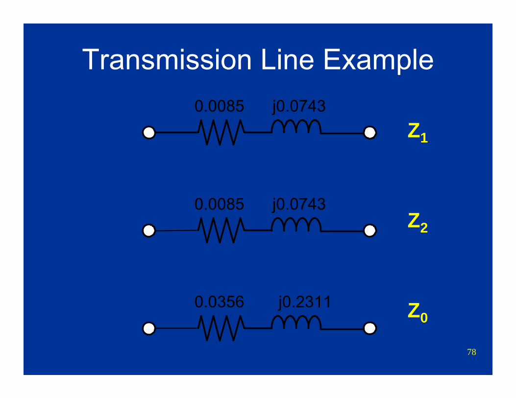
Transmission Line ExampleZ1 = Z2 = Ra + j (Xa + Xd)
= 0.0903 + j (0.372 + 0.4085) = 0.0903 + j 0.781 Ω /mile
Z1 Line = 50(0.0903 + j 0.781) = 4.52 + j 39.03 Ω = 39.29 Ω ∠ 83.4 °
Per unit @ 230 kV, 100 MVA Basebase MVA x ohms = pu Ω @ base MVA
kV2LL
Z1 Line = (4.52 + j 39.03)100/2302
= 0.0085 + j 0.0743 pu
77
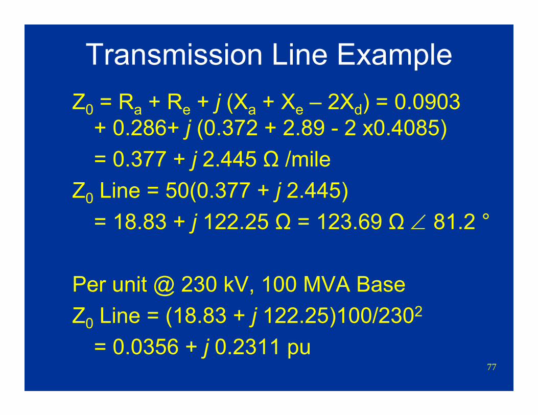
Transmission Line ExampleZ0 = Ra + Re + j (Xa + Xe – 2Xd) = 0.0903
+ 0.286+ j (0.372 + 2.89 - 2 x0.4085) = 0.377 + j 2.445 Ω /mile
Z0 Line = 50(0.377 + j 2.445) = 18.83 + j 122.25 Ω = 123.69 Ω ∠ 81.2 °
Per unit @ 230 kV, 100 MVA BaseZ0 Line = (18.83 + j 122.25)100/2302
= 0.0356 + j 0.2311 pu
78
Transmission Line Example
Z1
Z2
Z0
0.0085 j0.0743
0.0356 j0.2311
0.0085 j0.0743
79
Long Parallel LinesMutual impedance between lines
80
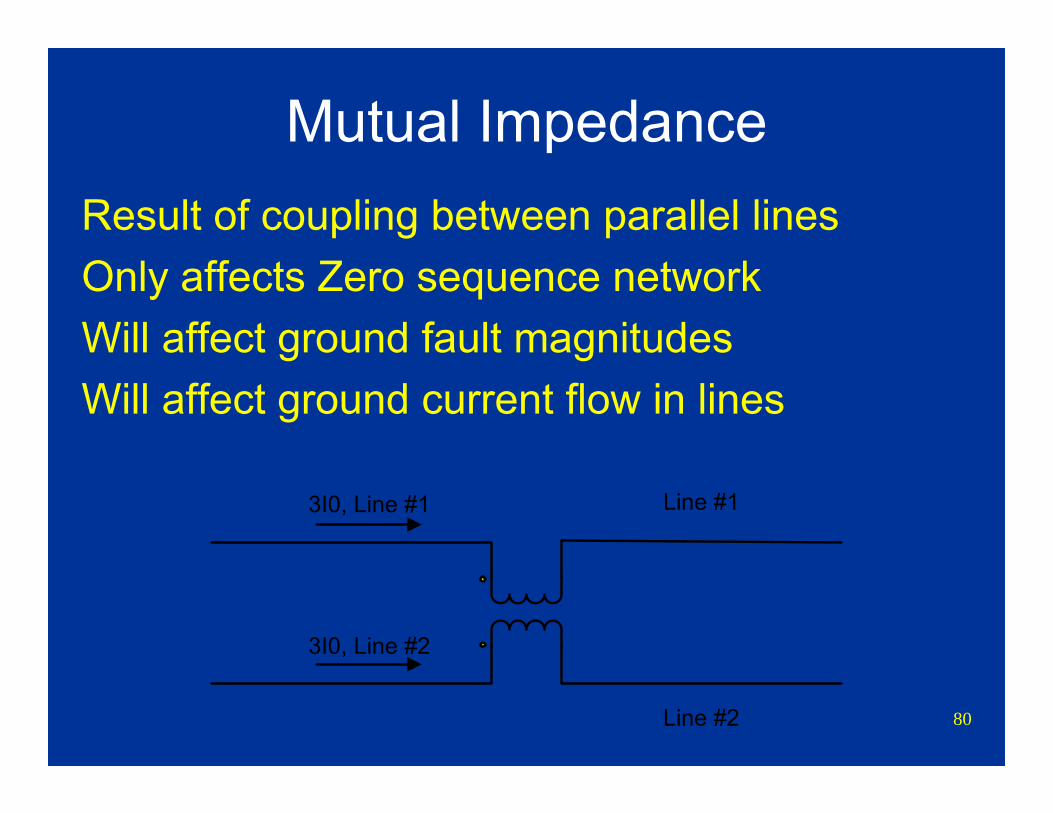
Mutual ImpedanceResult of coupling between parallel linesOnly affects Zero sequence networkWill affect ground fault magnitudesWill affect ground current flow in lines
Line #1
Line #2
3I0, Line #1
3I0, Line #2
81
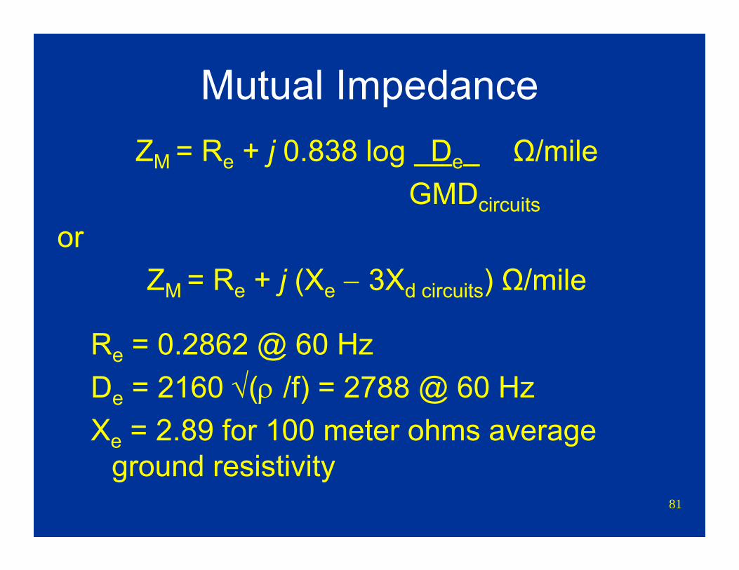
Mutual ImpedanceZM = Re + j 0.838 log De Ω/mile
GMDcircuits
or ZM = Re + j (Xe − 3Xd circuits) Ω/mile
Re = 0.2862 @ 60 HzDe = 2160 √(ρ /f) = 2788 @ 60 HzXe = 2.89 for 100 meter ohms average
ground resistivity

82
Mutual ImpedanceGMDcircuits is the ninth root of all possible
distances between the six conductors, approximately equal to center to center spacing
GMDcircuits = 9√(da1a2da1b2da1c2db1a2db1b2db1c2dc1a1dc1b2dc1c2)
Xd circuits = 0.2794 log GMDcircuits
83
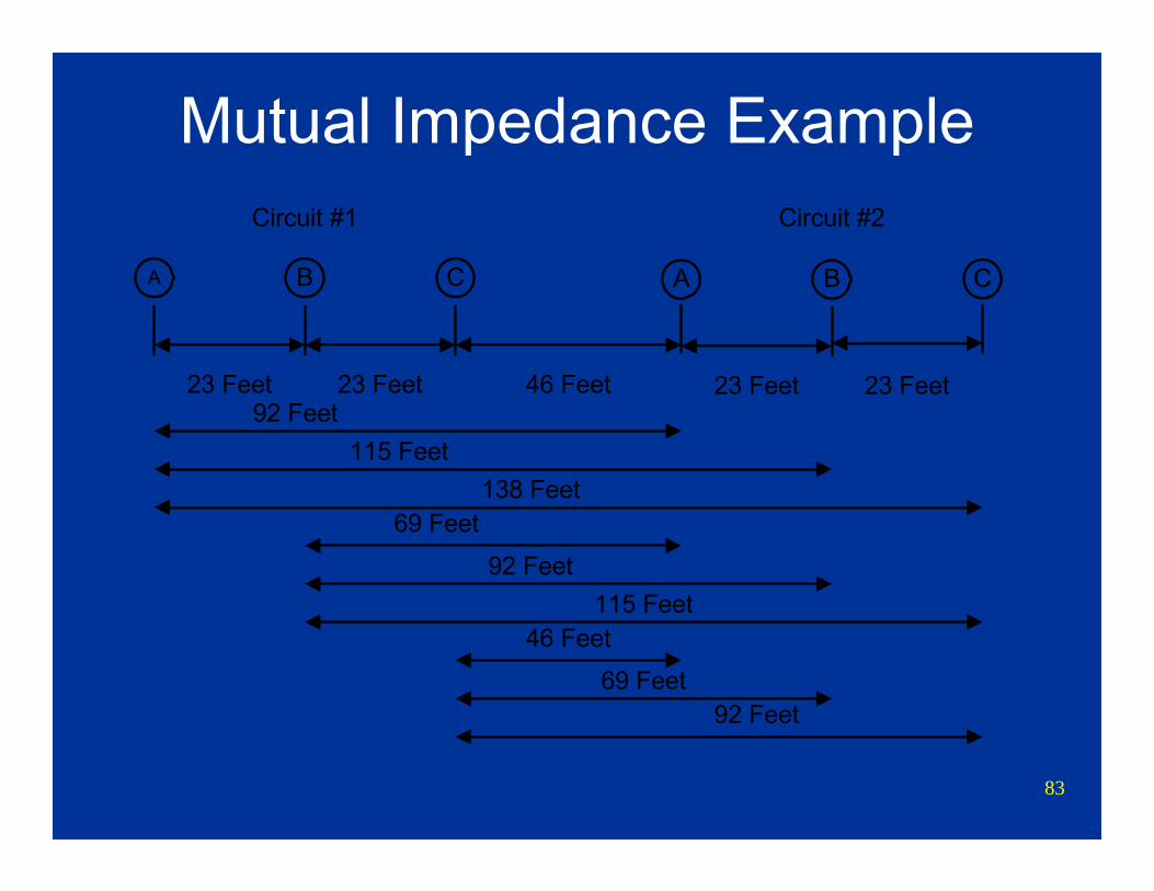
Mutual Impedance Example
A CB
23 Feet 23 Feet
A CB
23 Feet 23 Feet
Circuit #1 Circuit #2
46 Feet
46 Feet
92 Feet69 Feet
69 Feet
92 Feet115 Feet
138 Feet115 Feet
92 Feet
84
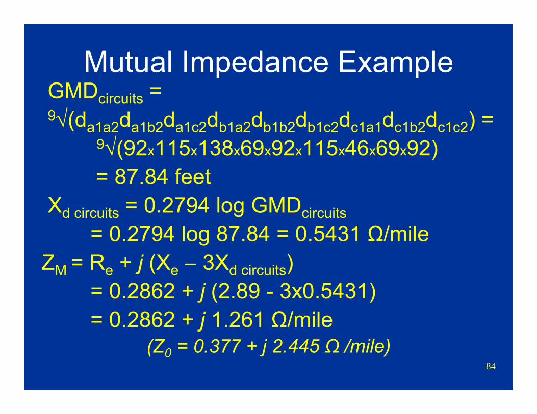
Mutual Impedance ExampleGMDcircuits = 9√(da1a2da1b2da1c2db1a2db1b2db1c2dc1a1dc1b2dc1c2) =
9√(92x115x138x69x92x115x46x69x92)= 87.84 feet
Xd circuits = 0.2794 log GMDcircuits = 0.2794 log 87.84 = 0.5431 Ω/mile
ZM = Re + j (Xe − 3Xd circuits) = 0.2862 + j (2.89 - 3x0.5431) = 0.2862 + j 1.261 Ω/mile
(Z0 = 0.377 + j 2.445 Ω /mile)
85
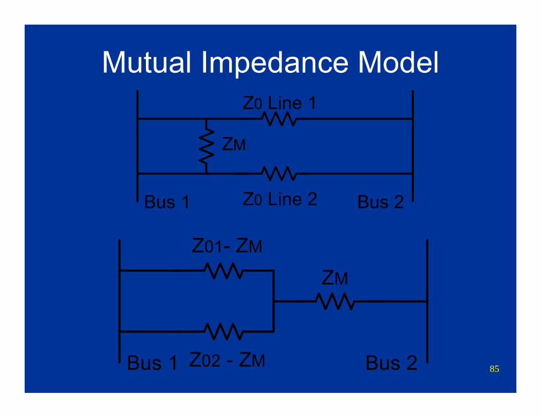
Mutual Impedance Model
Bus 1 Bus 2
Z0 Line 1
Z0 Line 2
ZM
Bus 1 Bus 2Z02 - ZM
Z01- ZM
ZM
86
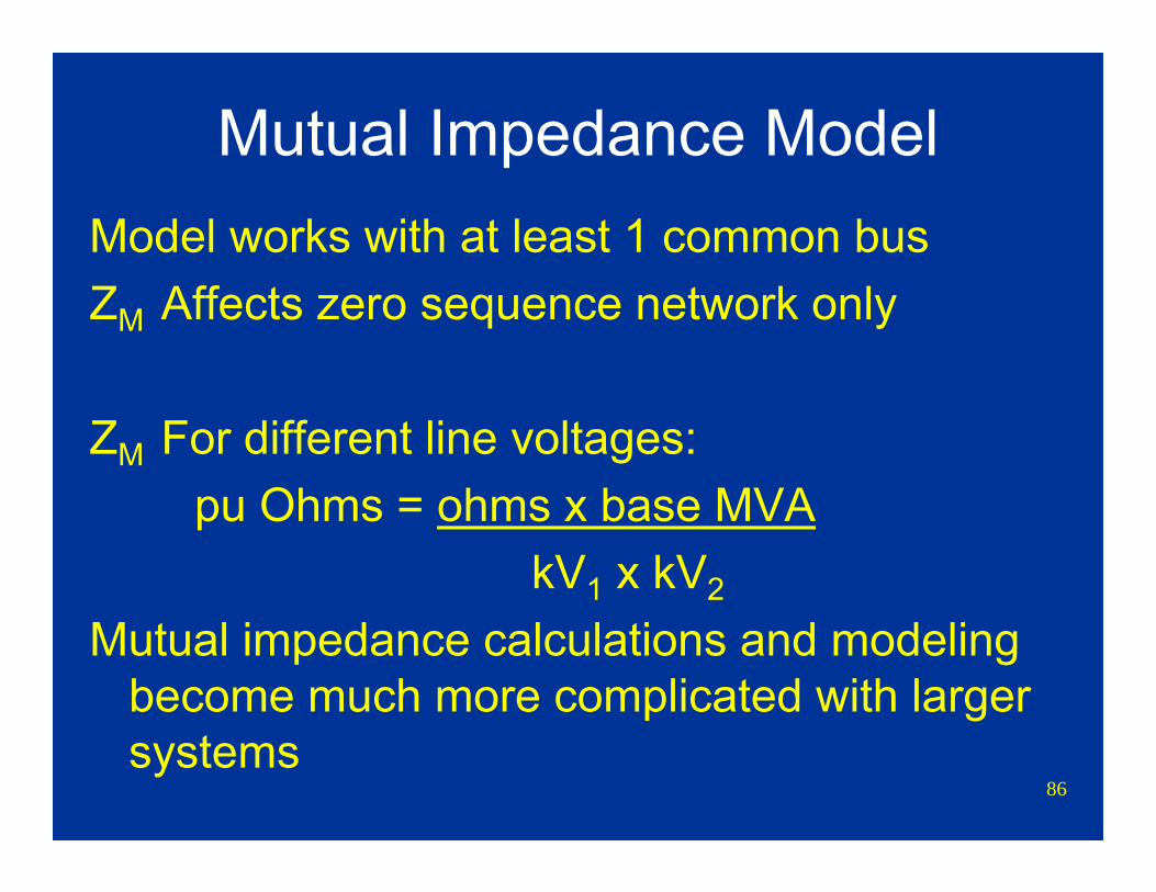
Mutual Impedance ModelModel works with at least 1 common busZM Affects zero sequence network only
ZM For different line voltages:pu Ohms = ohms x base MVA
kV1 x kV2
Mutual impedance calculations and modeling become much more complicated with larger systems
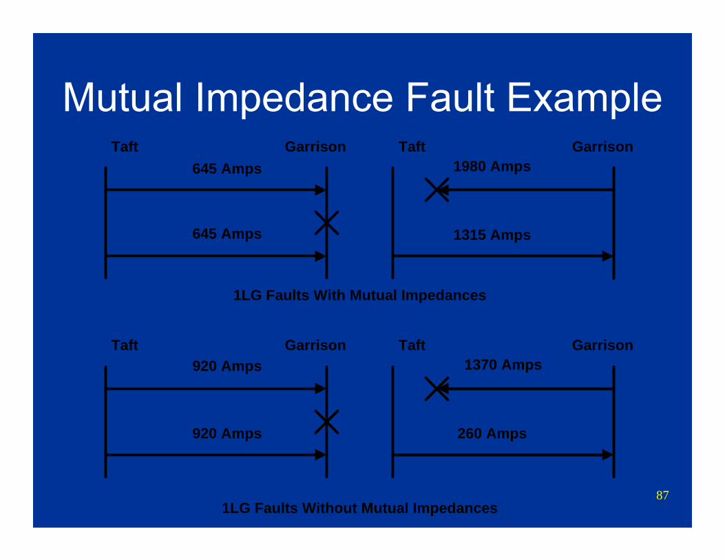
87
Mutual Impedance Fault ExampleTaft
Taft
645 Amps
1315 Amps645 Amps
1980 Amps
920 Amps
260 Amps920 Amps
1370 Amps
1LG Faults With Mutual Impedances
1LG Faults Without Mutual Impedances
Garrison
Garrison
Taft Garrison
Taft Garrison
88
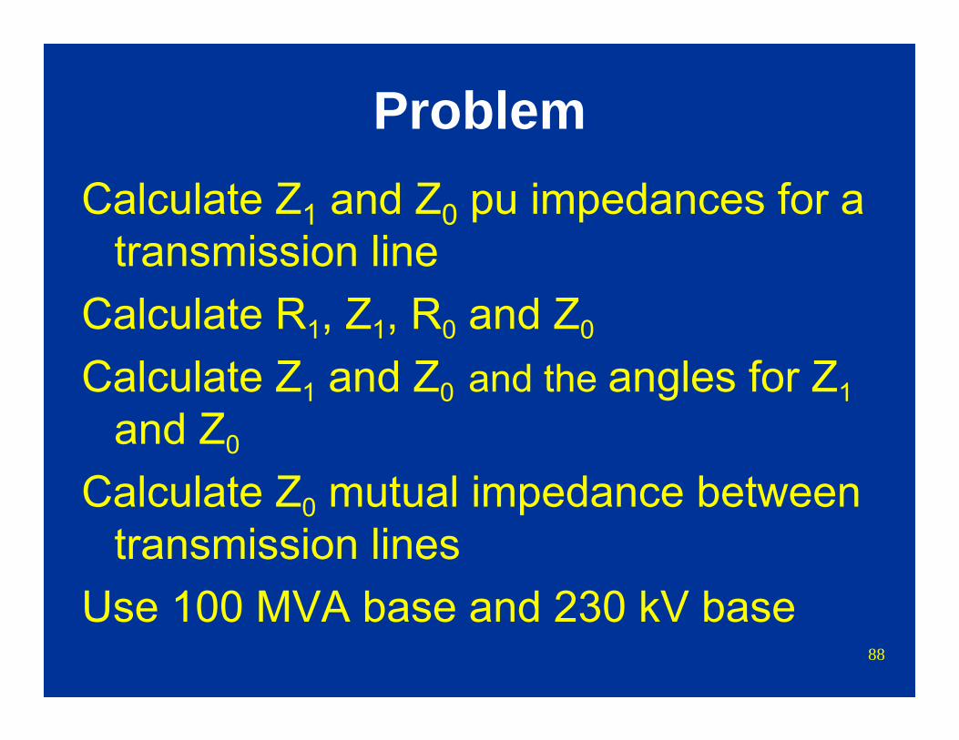
ProblemCalculate Z1 and Z0 pu impedances for a
transmission lineCalculate R1, Z1, R0 and Z0
Calculate Z1 and Z0 and the angles for Z1and Z0
Calculate Z0 mutual impedance between transmission lines
Use 100 MVA base and 230 kV base
89
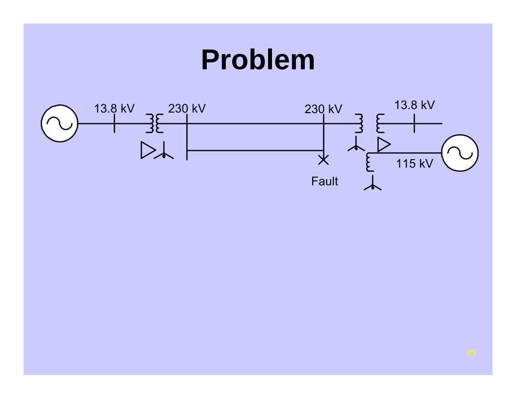
Problem
Fault
13.8 kV 13.8 kV230 kV230 kV
115 kV

90
Transmission Line Data2 Parallel 230 kV Lines
60 Miles long1272 kcmil ACSR Pheasant conductorRa = 0.0903 Ω /mile @ 80° CXa = 0.37201 Ω /mileGMR = 0.0466 feetH frame structure - flat, 23 feet between
conductorsSpacing between circuits = 92 feet centerline to
centerline
91
Fault Calculations and Impedance Network
Connections
92
Why We Need Fault StudiesRelay coordination and settingsDetermine equipment ratingsDetermine effective grounding of systemSubstation ground mat designSubstation telephone protection
requirementsLocating faults
93
Fault StudiesFault Types:
3 PhaseOne line to groundPhase to phasePhase to phase to ground
Fault Locations:Bus faultLine end Line out fault (bus fault with line open)Intermediate faults on transmission line

94
Fault Study AssumptionsIgnore loadsUse generator X”d
Generator X2 equal X”d
Ignore generator resistanceIgnore transformer resistance0 Ω Fault resistance assumedNegative sequence impedance = positive
sequence impedance
95
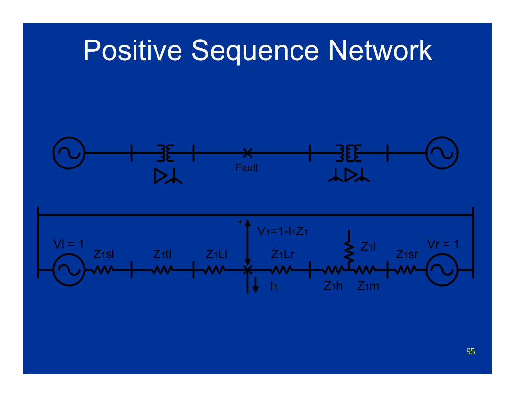
Positive Sequence Network
Z1sl Z1tl Z1Ll Z1Lr Z1sr
Z1h Z1m
Z1lV1=1-I1Z1
+
Vl = 1 Vr = 1
I1
Fault
96
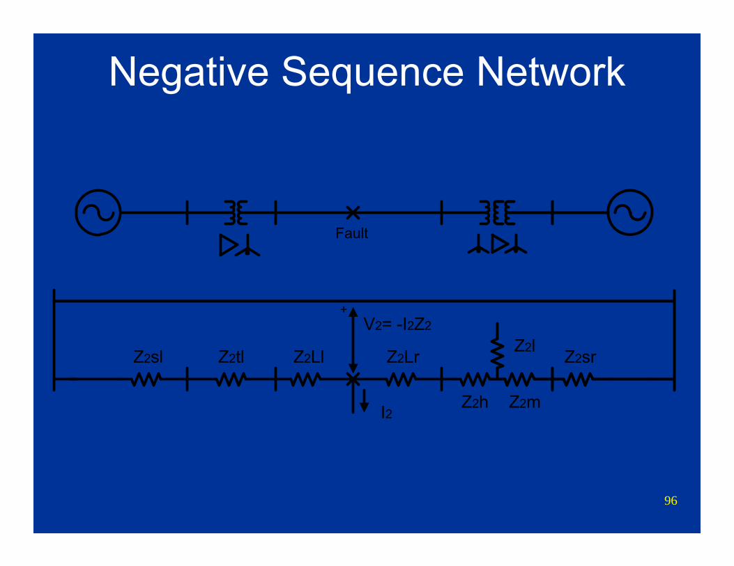
Negative Sequence Network
Z2sl Z2tl Z2Ll Z2Lr Z2sr
Z2h Z2m
Z2lV2= -I2Z2
+
I2
Fault
97
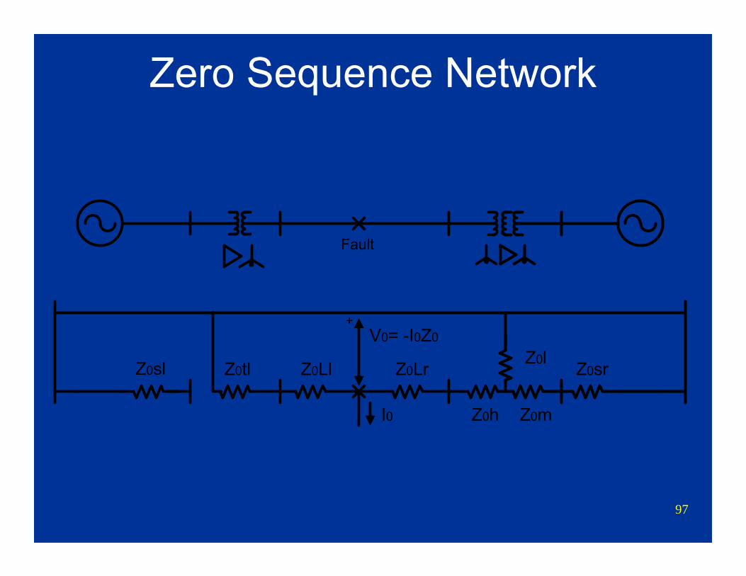
Zero Sequence Network
Z0sl Z0tl Z0Ll Z0Lr Z0sr
Z0h Z0m
Z0lV0= -I0Z0
+
I0
Fault
98
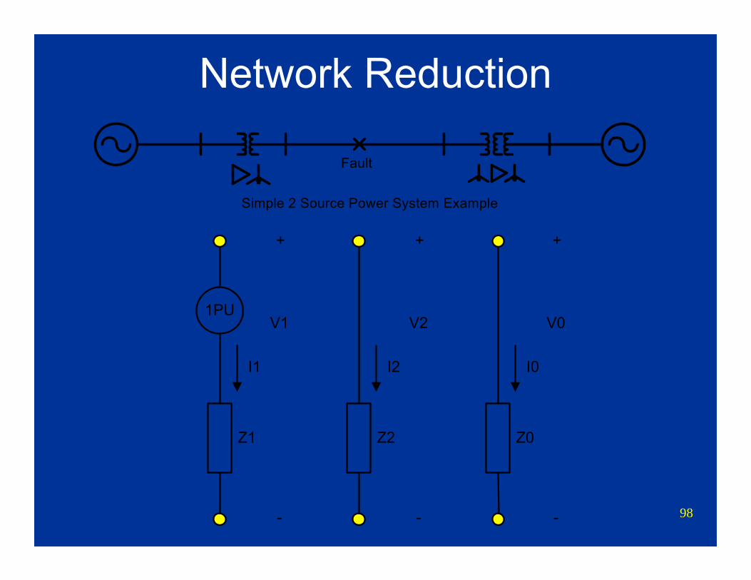
Network Reduction
Simple 2 Source Power System Example
Fault
1PU
Z1
I1
Z2
I2
Z0
I0
V0
-
+
V2
-
+
V1
-
+
99
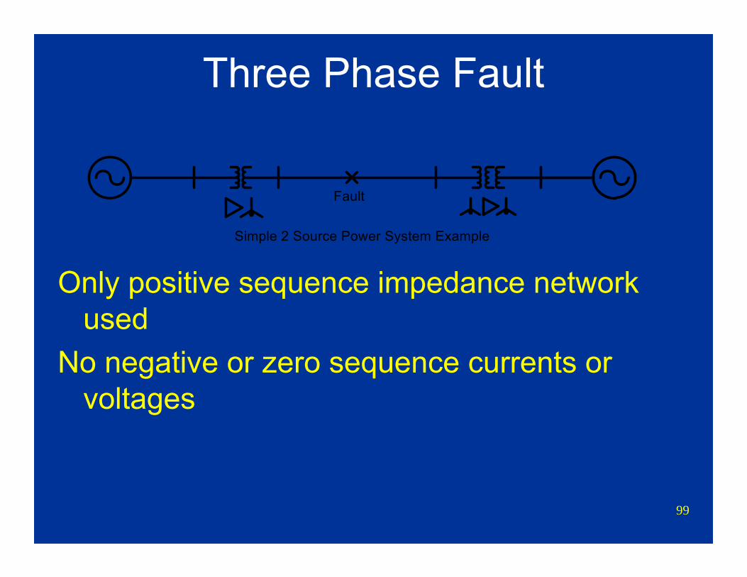
Three Phase Fault
Only positive sequence impedance network used
No negative or zero sequence currents or voltages
Simple 2 Source Power System Example
Fault
100
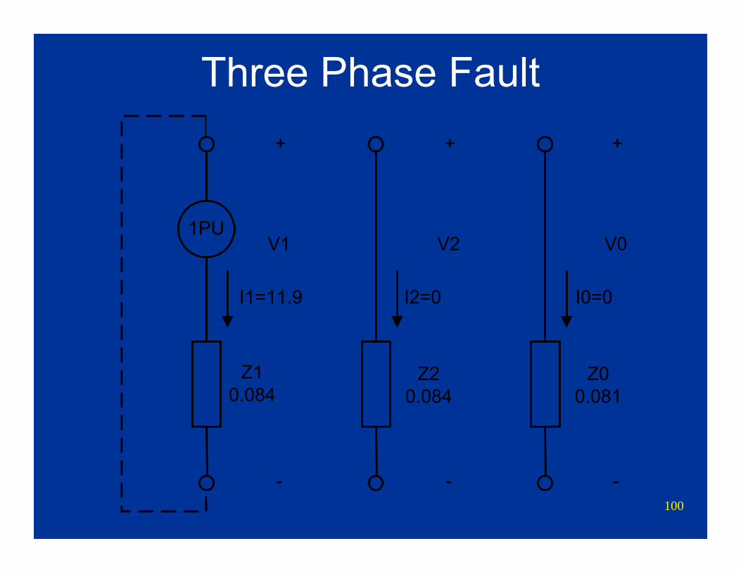
Three Phase Fault
1PU
Z10.084
I1=11.9 I2=0 I0=0
V0
-
+
V2
-
+
V1
-
+
Z00.081
Z20.084

101
Three Phase Fault
Simple 2 Source Power System Example
Fault
Z1sl Z1tl Z1Ll Z1Lr Z1sr
Z1h Z1m
Z1lV1=1-I1Z1
+
Vl = 1 Vr = 1
Sequence Network Connection for 3 Phase Fault
I10.1 0.0370.04 0.037 0.1
0.03
0.07
-0.007
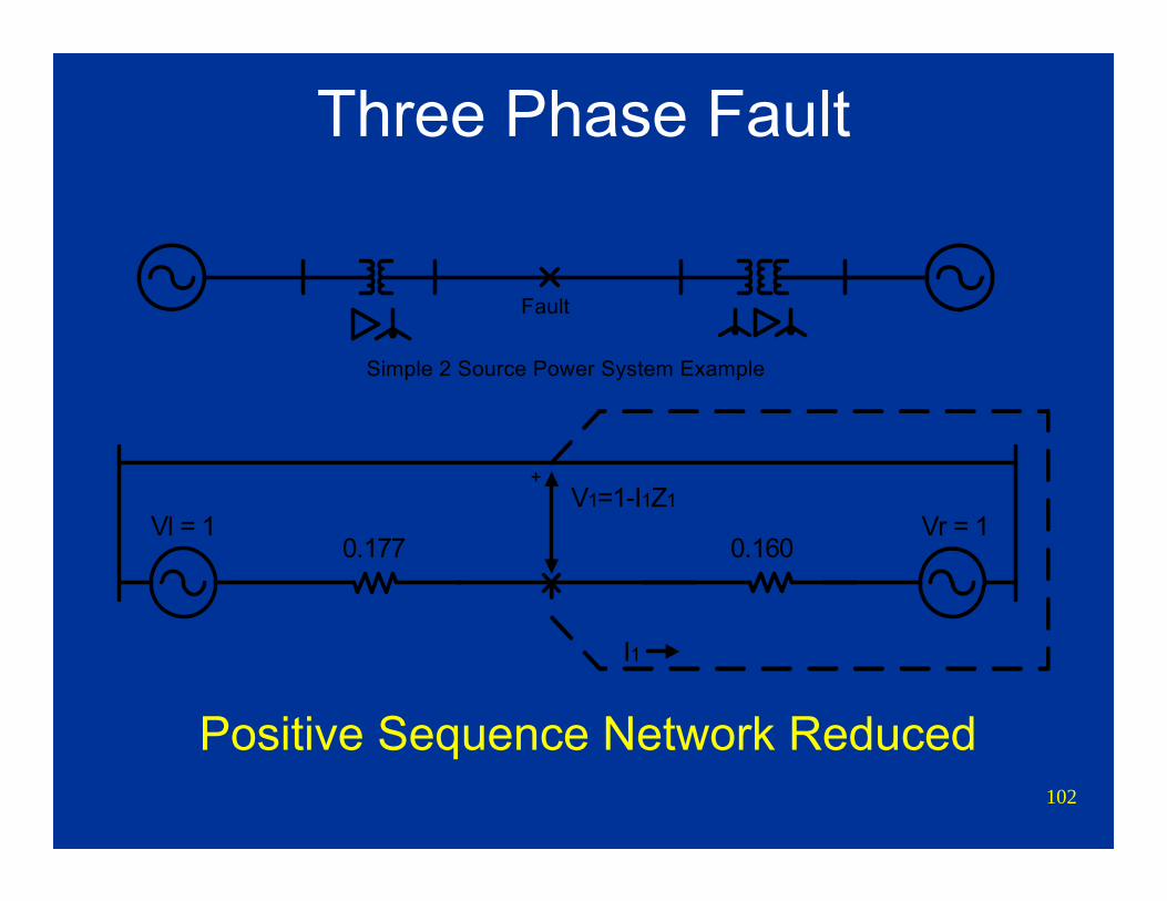
102
Three Phase Fault
Positive Sequence Network Reduced
Simple 2 Source Power System Example
Fault
V1=1-I1Z1+
Vl = 1 Vr = 1
I1
0.177 0.160
103
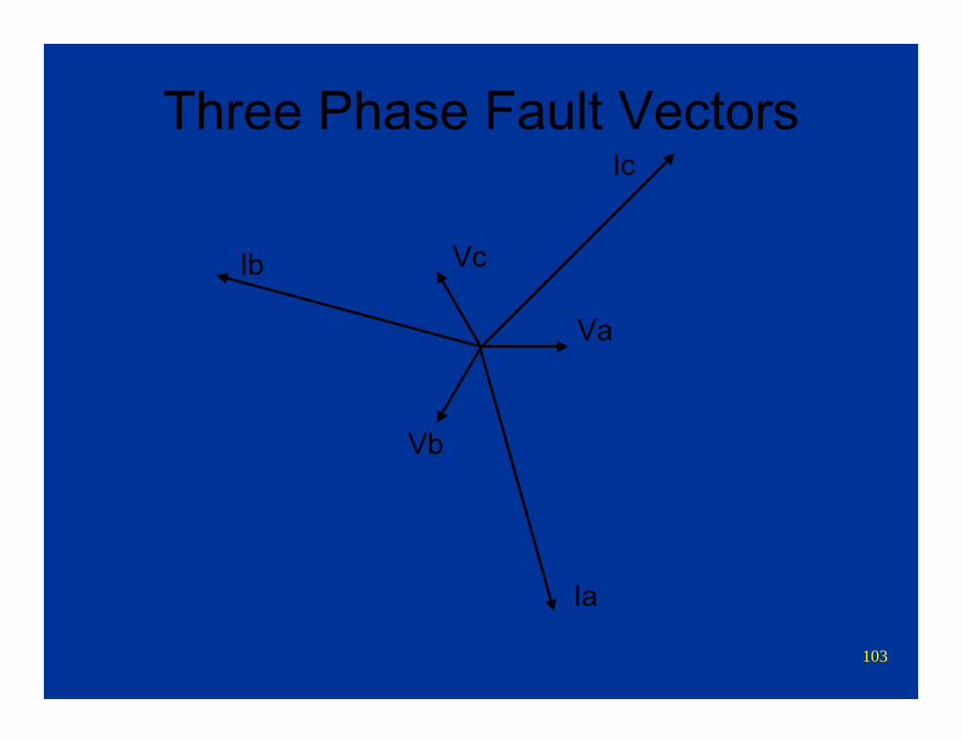
Three Phase Fault Vectors
Va
Vc
Vb
Ia
Ic
Ib
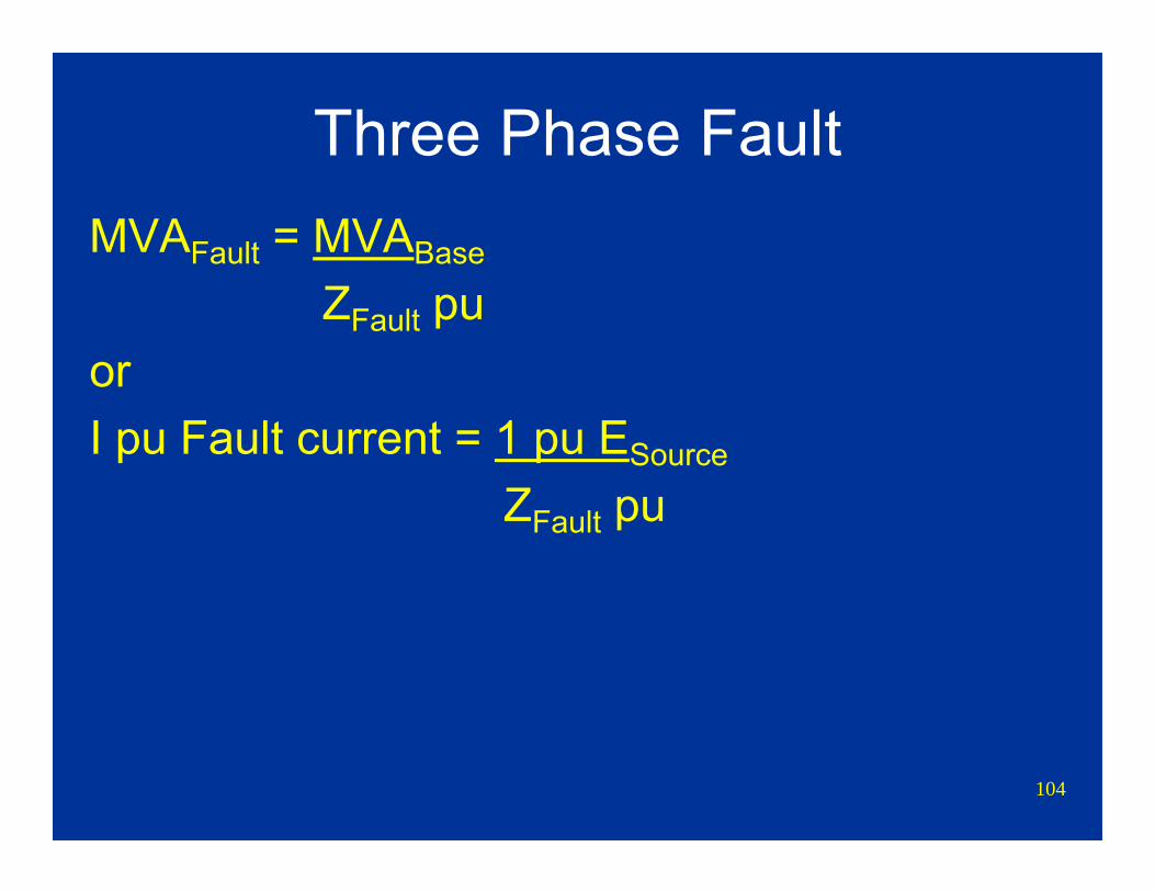
104
Three Phase FaultMVAFault = MVABase
ZFault puorI pu Fault current = 1 pu ESource
ZFault pu
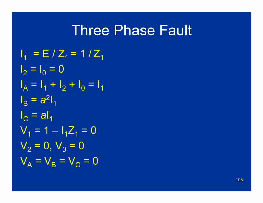
105
Three Phase FaultI1 = E / Z1 = 1 / Z1
I2 = I0 = 0IA = I1 + I2 + I0 = I1IB = a2I1IC = aI1V1 = 1 – I1Z1 = 0V2 = 0, V0 = 0VA = VB = VC = 0
106
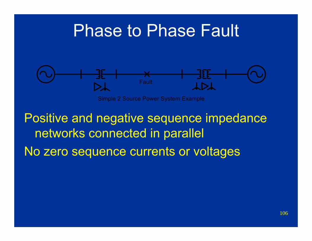
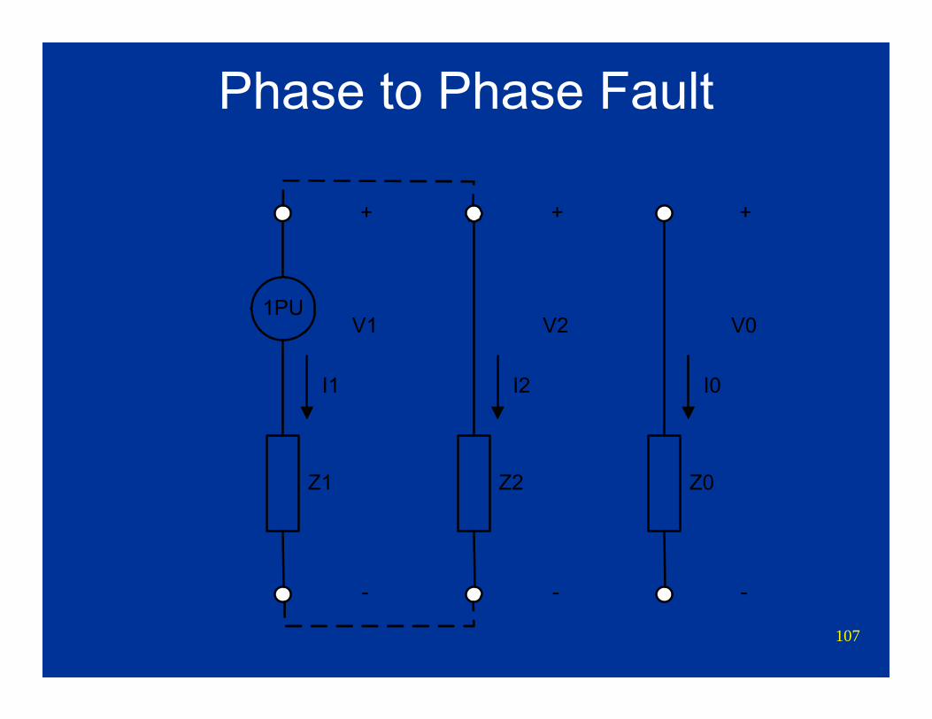
Phase to Phase Fault
Positive and negative sequence impedance networks connected in parallel
No zero sequence currents or voltages
Simple 2 Source Power System Example
Fault
107
Phase to Phase Fault
1PU
Z1
I1
Z2
I2
Z0
I0
V0
-
+
V2
-
+
V1
-
+
108
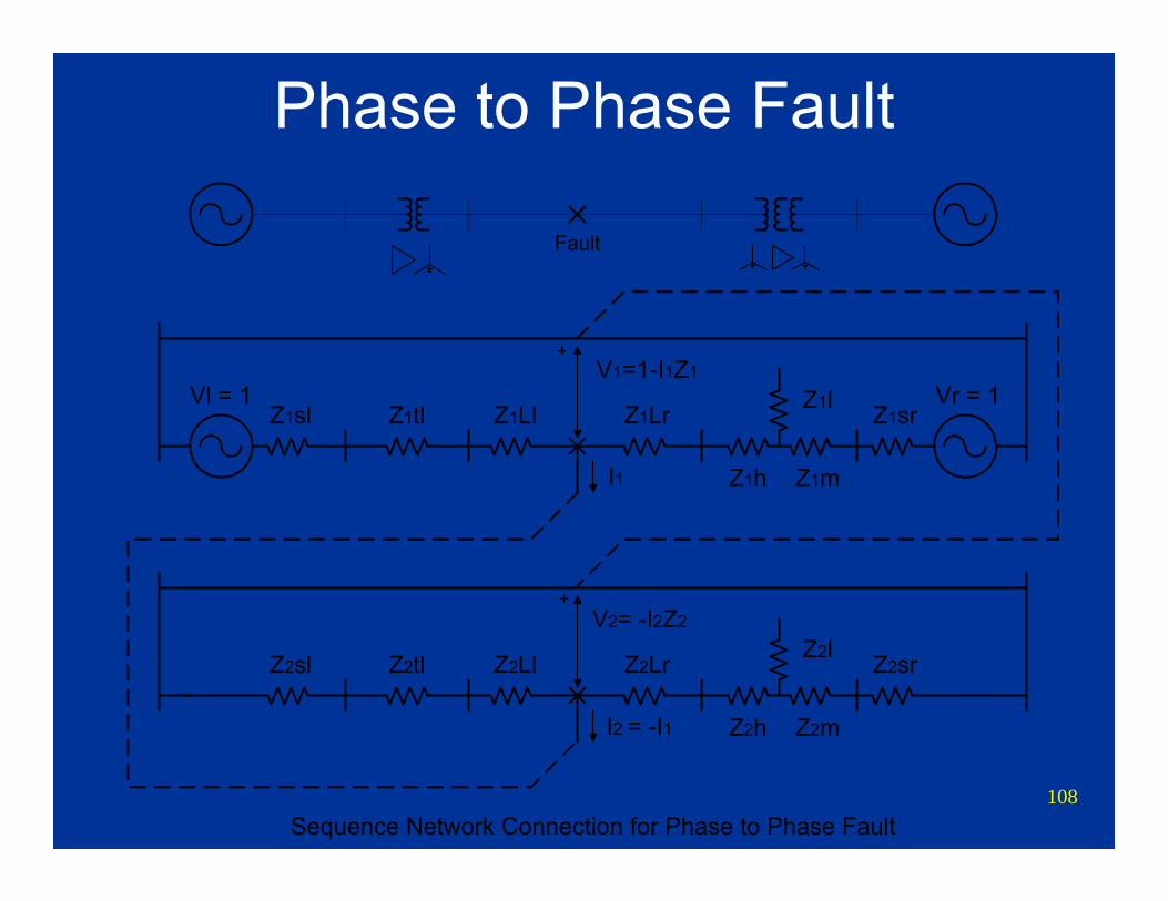
Phase to Phase Fault
Z2sl Z2tl Z2Ll Z2Lr Z2sr
Z2h Z2m
Z2lV2= -I2Z2
+
I2 = -I1
Z1sl Z1tl Z1Ll Z1Lr Z1sr
Z1h Z1m
Z1lV1=1-I1Z1
I1
+
Vl = 1 Vr = 1
Sequence Network Connection for Phase to Phase Fault
Fault
109
Phase to Phase Fault Vectors
Va
Vc
Vb
Ic
Ib
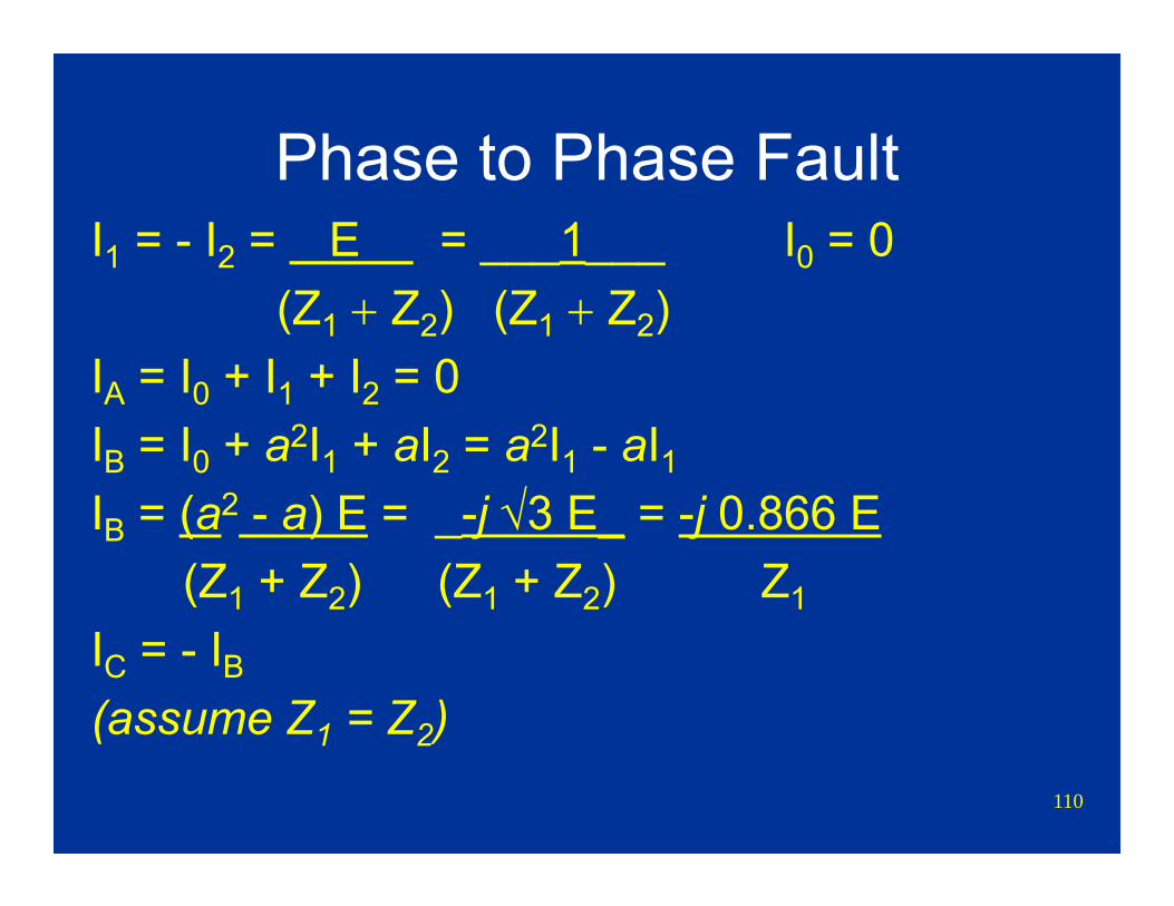
110
Phase to Phase FaultI1 = - I2 = E = ___1___ I0 = 0
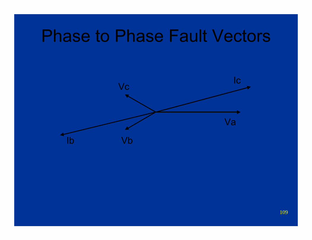
(Z1 + Z2) (Z1 + Z2)IA = I0 + I1 + I2 = 0IB = I0 + a2I1 + aI2 = a2I1 - aI1IB = (a2 - a) E = _-j √3 E_ = -j 0.866 E
(Z1 + Z2) (Z1 + Z2) Z1
IC = - IB(assume Z1 = Z2)
111
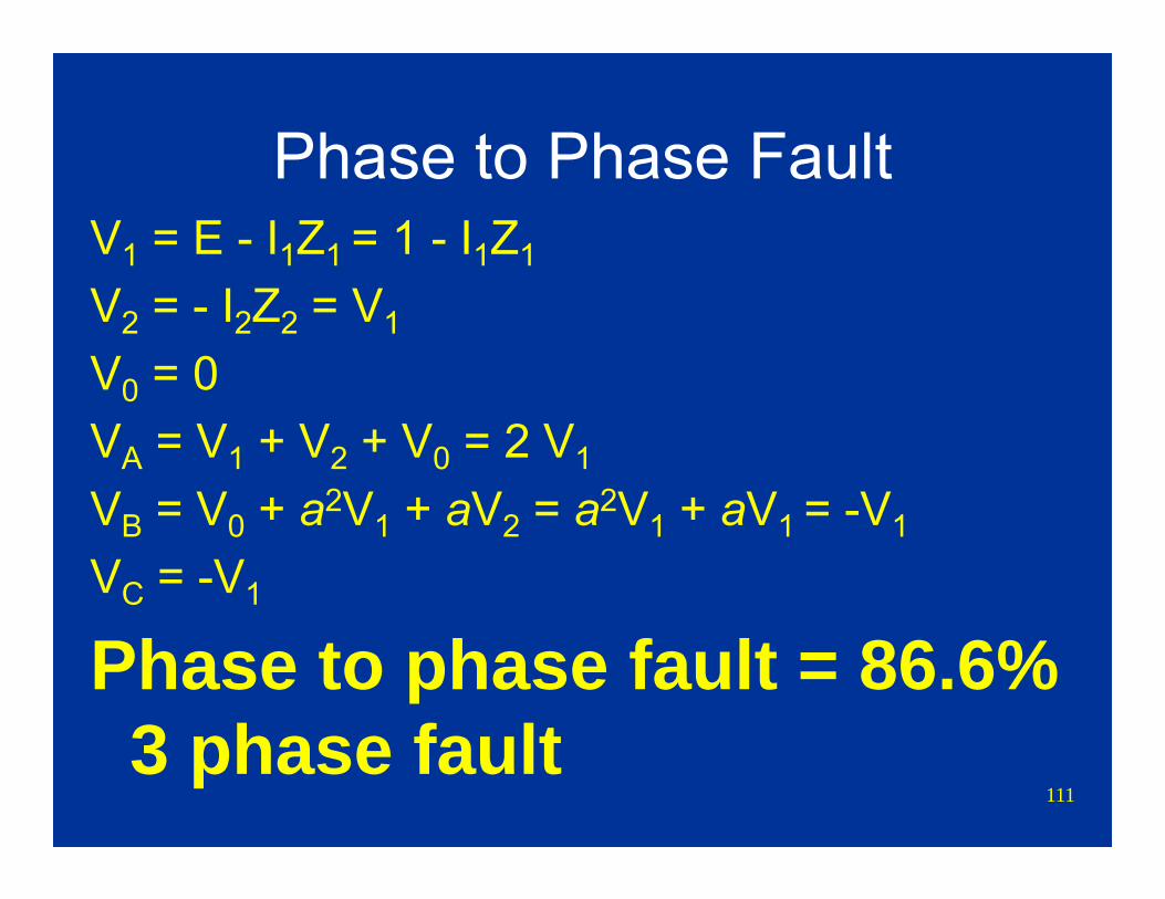
Phase to Phase FaultV1 = E - I1Z1 = 1 - I1Z1
V2 = - I2Z2 = V1
V0 = 0VA = V1 + V2 + V0 = 2 V1
VB = V0 + a2V1 + aV2 = a2V1 + aV1 = -V1
VC = -V1
Phase to phase fault = 86.6% 3 phase fault
112
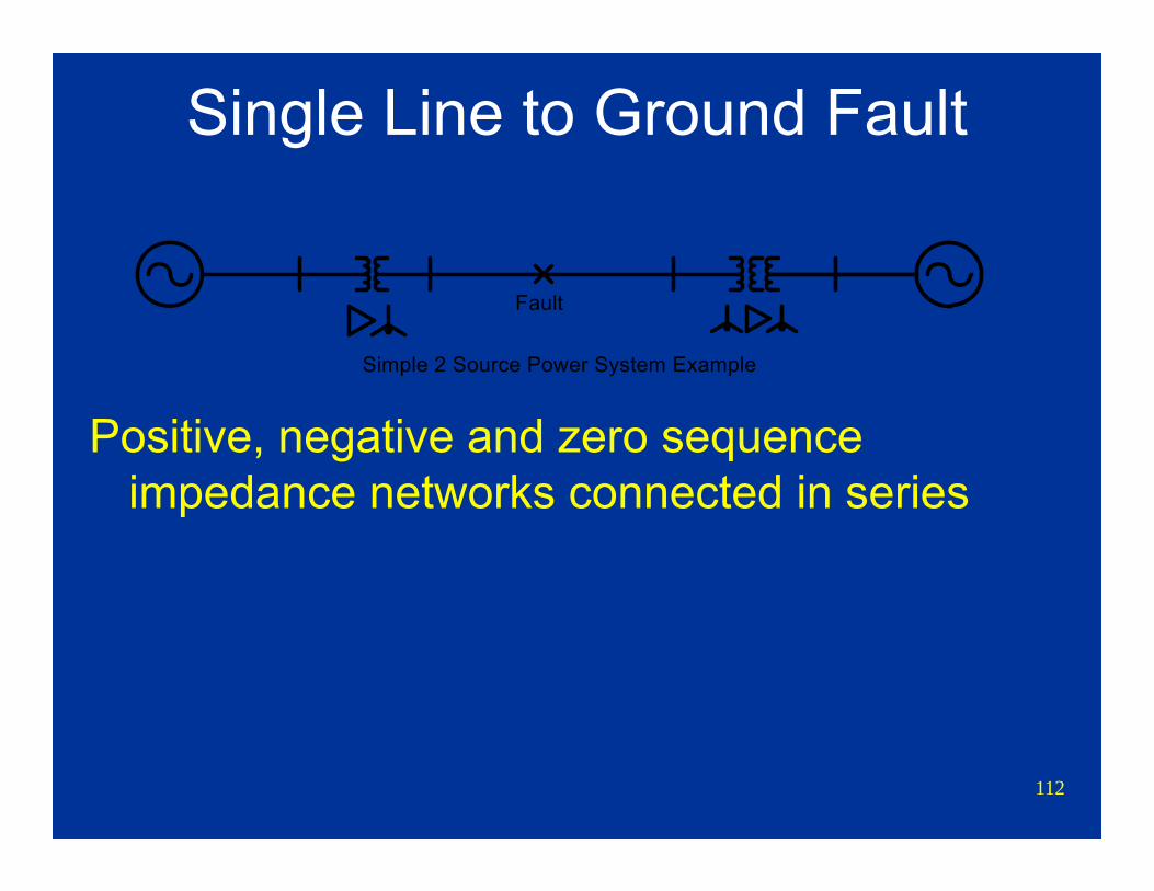
Single Line to Ground Fault
Positive, negative and zero sequence impedance networks connected in series
Simple 2 Source Power System Example
Fault

113
Single Line to Ground Fault
1PU
Z1.084
I0=4.02
V0
-
+
V2
-
+
V1
-
+
Z2.084
Z0.081
I2=4.02I1=4.02
114
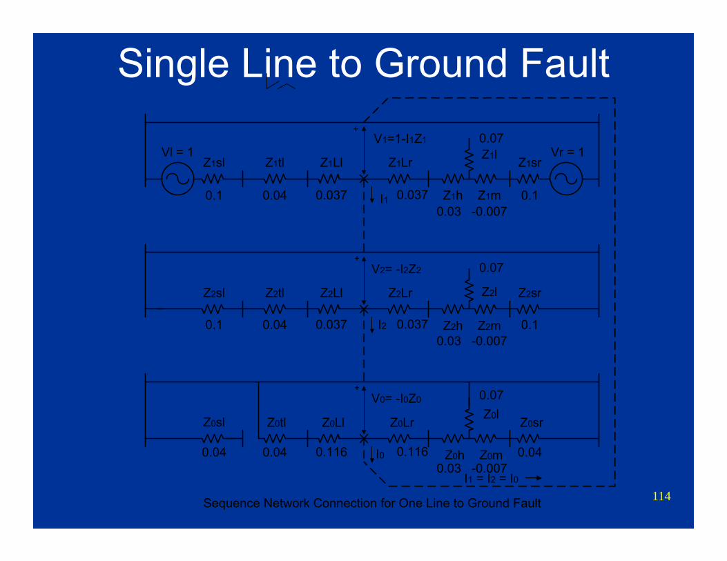
Single Line to Ground Fault
Z2sl Z2tl Z2Ll Z2Lr Z2sr
Z2h Z2m
Z2l
V2= -I2Z2+
Z0sl Z0tl Z0Ll Z0Lr Z0sr
Z0h Z0m
Z0lV0= -I0Z0
+
Z1sl Z1tl Z1Ll Z1Lr Z1sr
Z1h Z1m
Z1lV1=1-I1Z1
+
Vl = 1 Vr = 1
I1
I2
I0
Sequence Network Connection for One Line to Ground Fault
I1 = I2 = I0
0.1 0.0370.04 0.037 0.10.03
0.07
-0.007
0.04 0.1160.04 0.116 0.040.03
0.07
-0.007
0.1 0.0370.04 0.037 0.10.03
0.07
-0.007
115
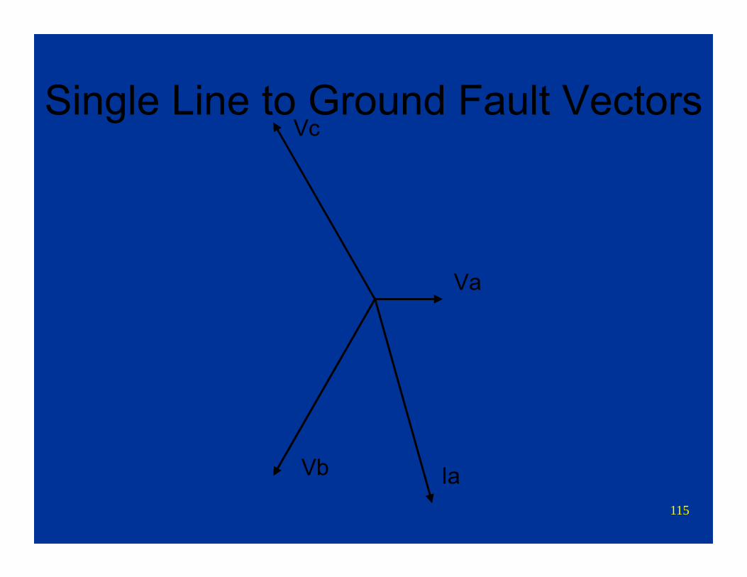
Single Line to Ground Fault Vectors
Va
Vc
Vb Ia
116
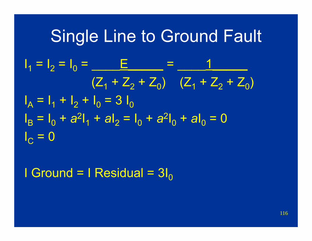
Single Line to Ground FaultI1 = I2 = I0 = ____E_____ = ____1_____
(Z1 + Z2 + Z0) (Z1 + Z2 + Z0)IA = I1 + I2 + I0 = 3 I0IB = I0 + a2I1 + aI2 = I0 + a2I0 + aI0 = 0IC = 0
I Ground = I Residual = 3I0
117
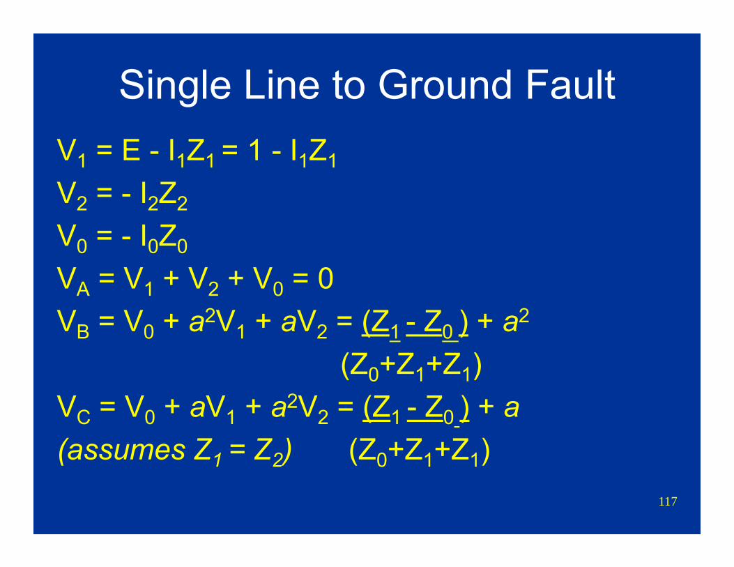
Single Line to Ground FaultV1 = E - I1Z1 = 1 - I1Z1
V2 = - I2Z2
V0 = - I0Z0
VA = V1 + V2 + V0 = 0VB = V0 + a2V1 + aV2 = (Z1 - Z0 ) + a2
(Z0+Z1+Z1)VC = V0 + aV1 + a2V2 = (Z1 - Z0 ) + a(assumes Z1 = Z2) (Z0+Z1+Z1)
118
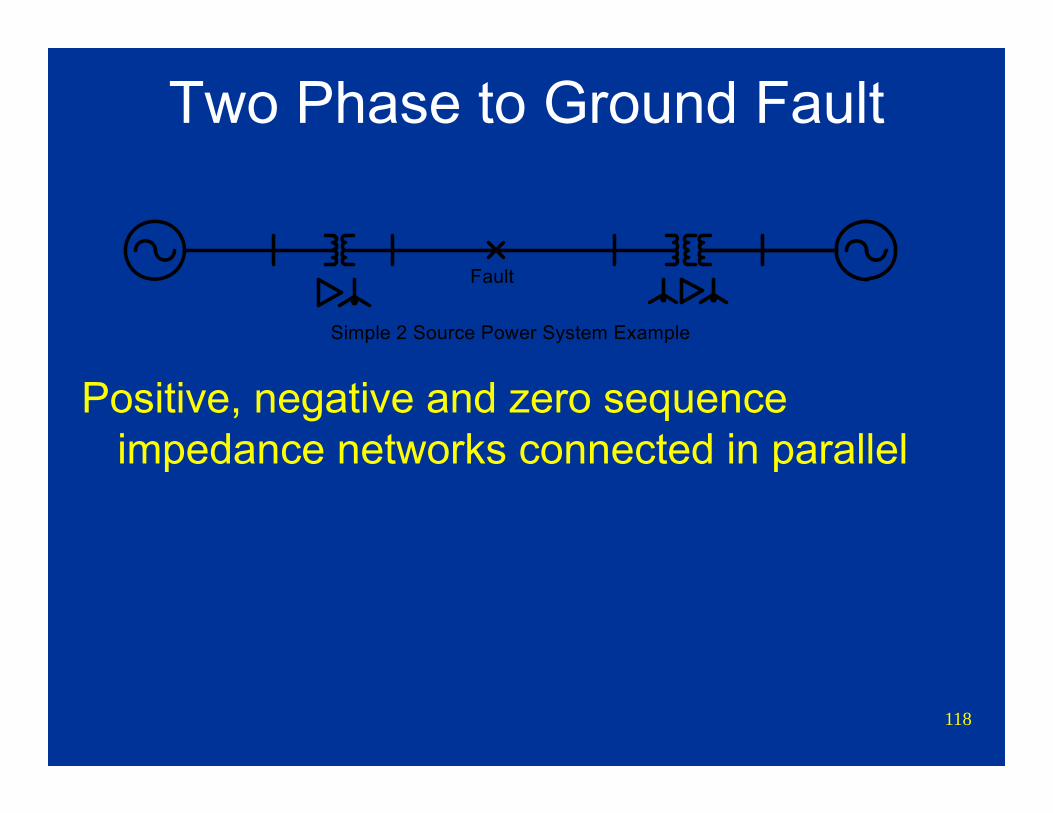
Two Phase to Ground Fault
Positive, negative and zero sequence impedance networks connected in parallel
Simple 2 Source Power System Example
Fault

119
Two Phase to Ground Fault
1PU
Z1
I1
Z2
I2
Z0
I0
V0
-
+
V2
-
+
V1
-
+

120
Two Phase to Ground Fault
Z2sl Z2tl Z2Ll Z2Lr Z2sr
Z2h Z2m
Z2lV2= -I2Z2
+
Z0sl Z0tl Z0Ll Z0Lr Z0sr
Z0h Z0m
Z0lV0= -I0Z0
+
Z1sl Z1tl Z1Ll Z1Lr Z1sr
Z1h Z1m
Z1lV1=1-I1Z1
+
Vl = 1 Vr = 1
I1
I2
I0
Sequence Network Connection for Phase to Phase to Ground Fault
121
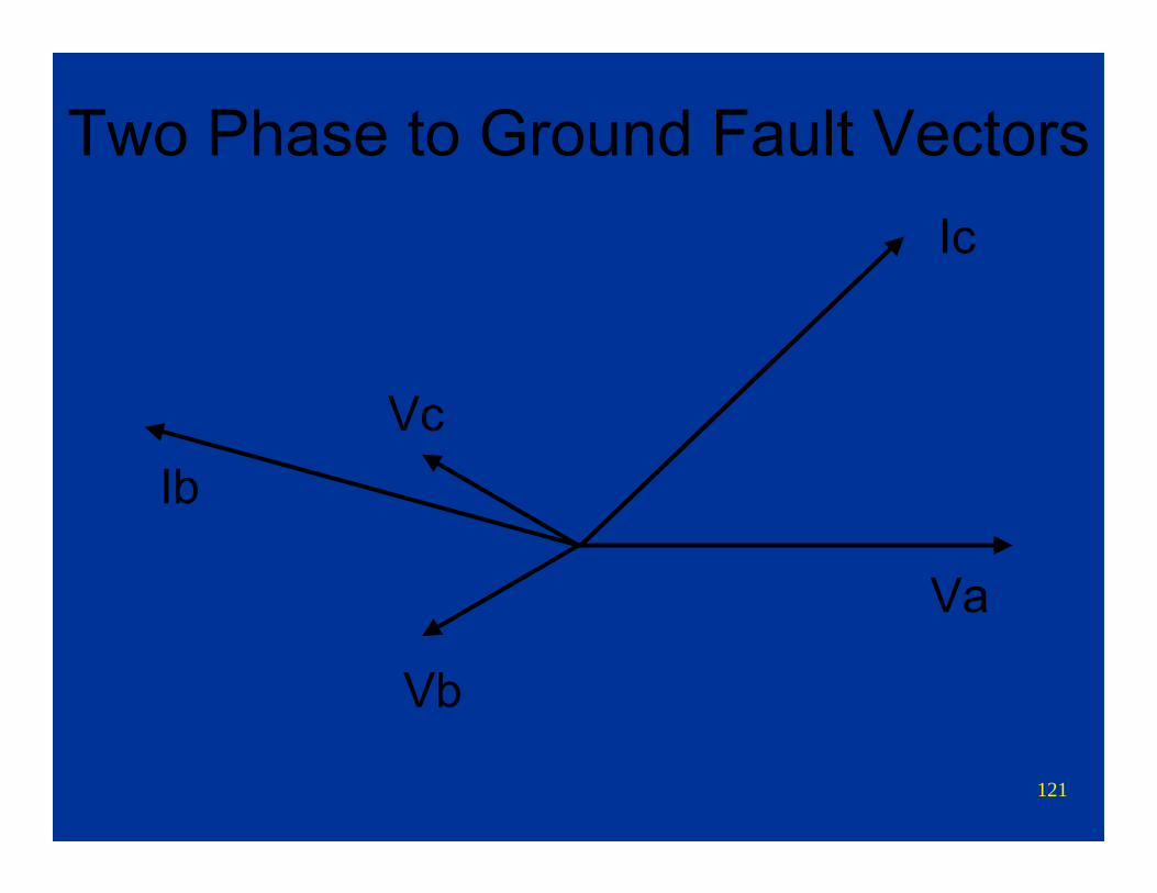
Two Phase to Ground Fault Vectors
Va
Vc
Vb
Ic
Ib
122
Other ConditionsFault calculations and symmetrical
components can also be used to evaluate:Open pole or broken conductorUnbalanced loadsLoad included in fault analysisTransmission line fault location
For these other network conditions, refer to references.
123
ReferencesCircuit Analysis of AC Power Systems, Vol. 1 &
2, Edith ClarkeElectrical Transmission and Distribution
Reference Book, Westinghouse Electric Co., East Pittsburgh, Pa.
Symmetrical Components, Wagner and Evans, McGraw-Hill Publishing Co.
Symmetrical Components for Power Systems Engineering, J. Lewis Blackburn, Marcel Dekker, Inc.
124
The end
Jon F. DaumeBonneville Power Administration
Retired!
1
Hands-On Relay School
Jon F. DaumeBonneville Power Administration
March 14-15, 2011
Theory TrackTransmission Protection Theory
Transmission System Protection
2
Discussion Topics• Protection overview• Transmission line protection
– Phase and ground fault protection– Line differentials– Pilot schemes– Relay communications– Automatic reclosing
• Breaker failure relays• Special protection or remedial action schemes
3
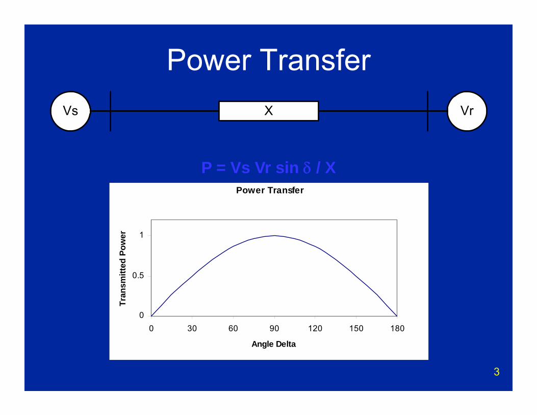
Power TransferVs VrX
Power Transfer
0
0.5
1
0 30 60 90 120 150 180
Angle Delta
Tran
smitt
ed P
ower
P = Vs Vr sin δ / X
4
Increase Power Transfer• Increase transmission system operating
voltage• Increase angle δ• Decrease X
– Add additional transmission lines– Add series capacitors to existing lines
5
6
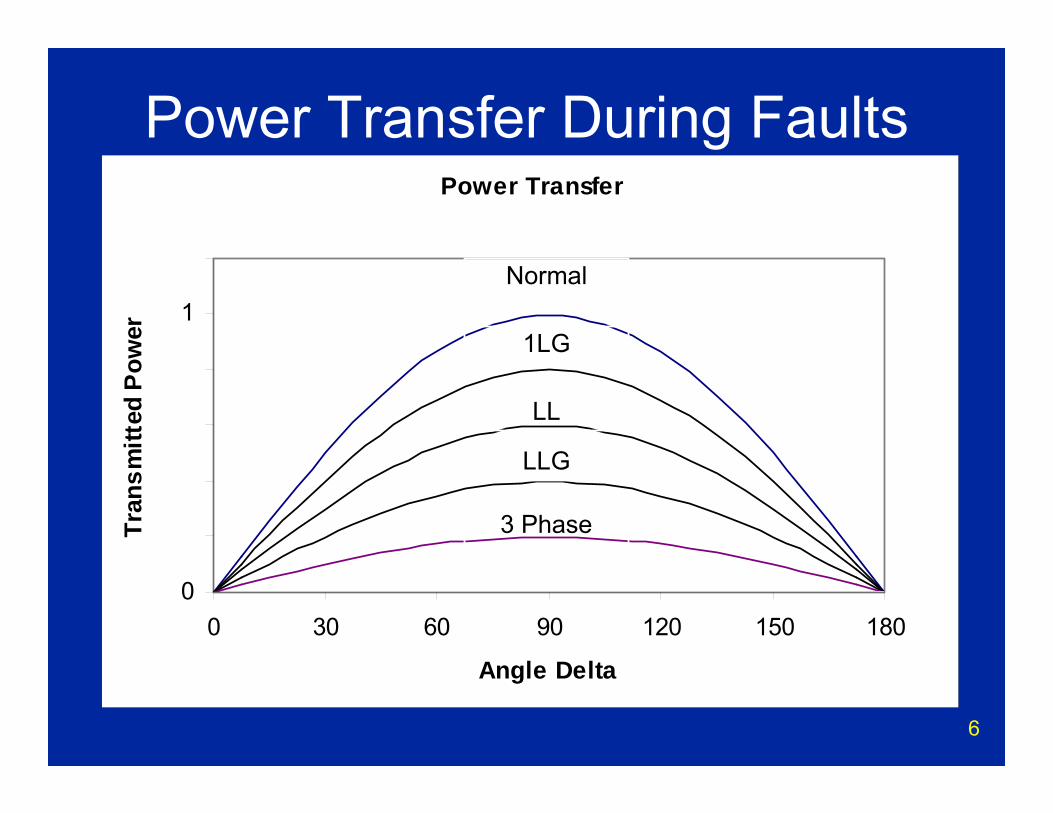
Power Transfer During FaultsPower Transfer
0
0.2
0.4
0.6
0.8
1
1.2
0 30 60 90 120 150 180
Angle Delta
Tran
smitt
ed P
ower
Normal
1LG
LL
LLG
3 Phase
7
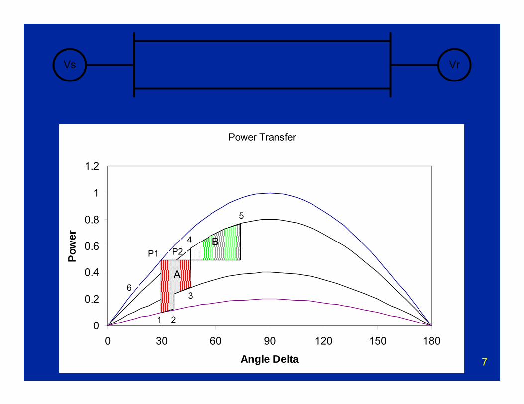
Vs Vr
Power Transfer
0
0.2
0.4
0.6
0.8
1
1.2
0 30 60 90 120 150 180
Angle Delta
Pow
er BP1
3
21
P2
6
4
5
A
8
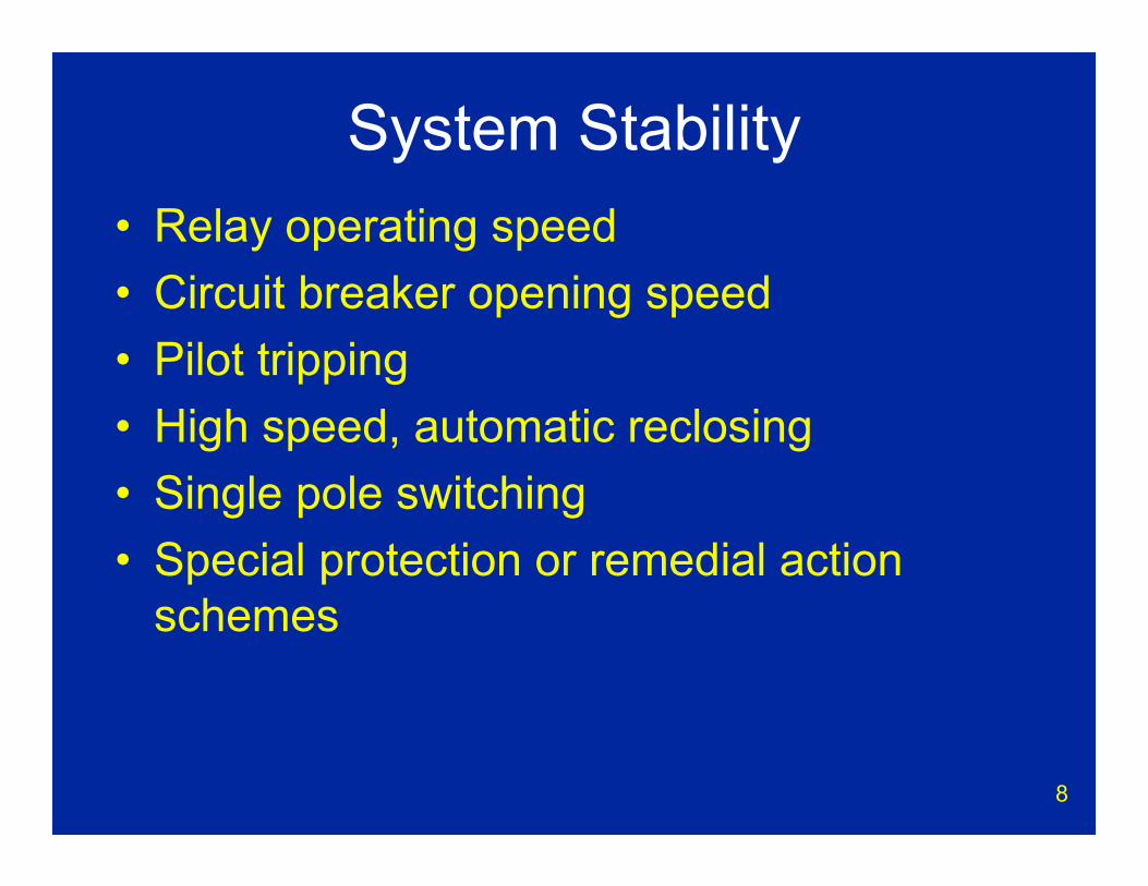
System Stability• Relay operating speed • Circuit breaker opening speed• Pilot tripping• High speed, automatic reclosing• Single pole switching• Special protection or remedial action
schemes
9
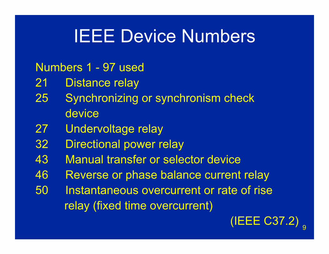
IEEE Device NumbersNumbers 1 - 97 used21 Distance relay25 Synchronizing or synchronism check
device27 Undervoltage relay32 Directional power relay43 Manual transfer or selector device46 Reverse or phase balance current relay50 Instantaneous overcurrent or rate of rise
relay (fixed time overcurrent)(IEEE C37.2)

10
51 AC time overcurrent relay52 AC circuit breaker59 Overvoltage relay62 Time delay stopping or opening relay63 Pressure switch67 AC directional overcurrent relay 79 AC reclosing relay81 Frequency relay86 Lock out relay87 Differential relay
(IEEE C37.2)
IEEE Device Numbers
11
Relay Reliability• Overlapping protection
– Relay systems are designed with a high level of dependability
– This includes redundant relays– Overlapping protection zones
• We will trip no line before its time– Relay system security is also very important– Every effort is made to avoid false trips
12
Relay Reliability• Relay dependability (trip when required)
– Redundant relays– Remote backup– Dual trip coils in circuit breaker– Dual batteries– Digital relay self testing– Thorough installation testing– Routine testing and maintenance– Review of relay operations
13
Relay Reliability• Relay security (no false trip)
– Careful evaluation before purchase– Right relay for right application– Voting
• 2 of 3 relays must agree before a trip– Thorough installation testing – Routine testing and maintenance– Review of relay operations
14
Transmission Line Protection

15
Western Transmission System
Northwest includes Oregon, Washington, Idaho, Montana, northern Nevada, Utah, British Columbia and Alberta.WECC is Western Electricity Coordinating Council
which includes states and provinces west of Rocky Mountains.
Voltage, kV Northwest WECC115 - 161 27400 miles 48030 miles
230 20850 miles 41950 miles
287 - 345 4360 miles 9800 miles
500 9750 miles 16290 miles
260 - 500 DC 300 miles 1370 miles
16
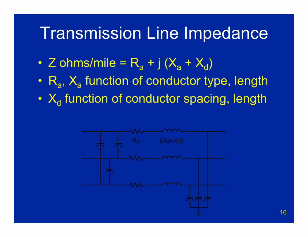
Transmission Line Impedance• Z ohms/mile = Ra + j (Xa + Xd)• Ra, Xa function of conductor type, length• Xd function of conductor spacing, length
Ra j(Xa+Xd)
17
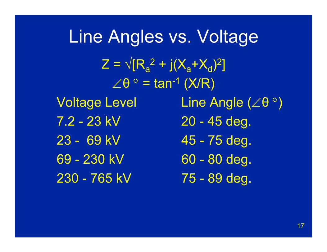
Line Angles vs. VoltageZ = √[Ra
2 + j(Xa+Xd)2]∠θ ° = tan-1 (X/R)
Voltage Level Line Angle (∠θ °)7.2 - 23 kV 20 - 45 deg.23 - 69 kV 45 - 75 deg.69 - 230 kV 60 - 80 deg.230 - 765 kV 75 - 89 deg.
18
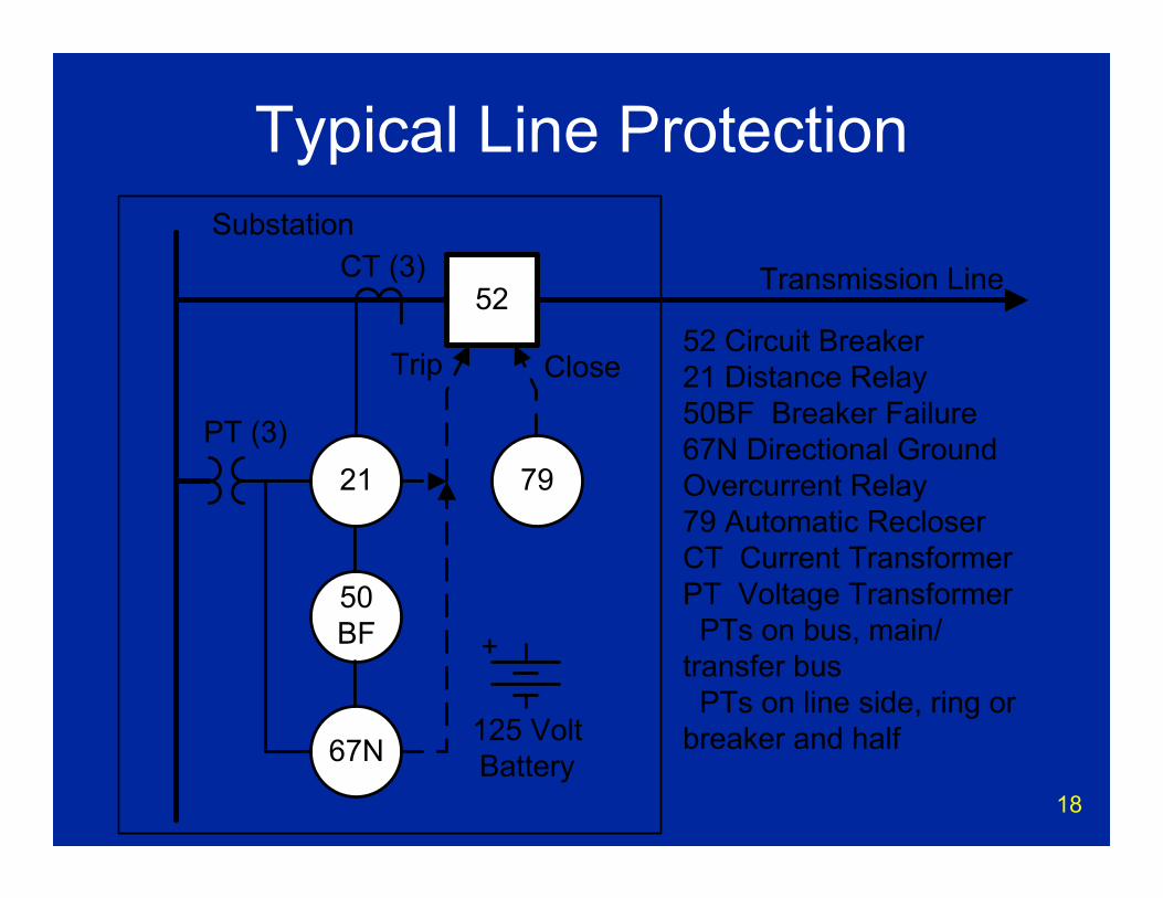
Typical Line Protection
19
Distance Relays(21, 21G)
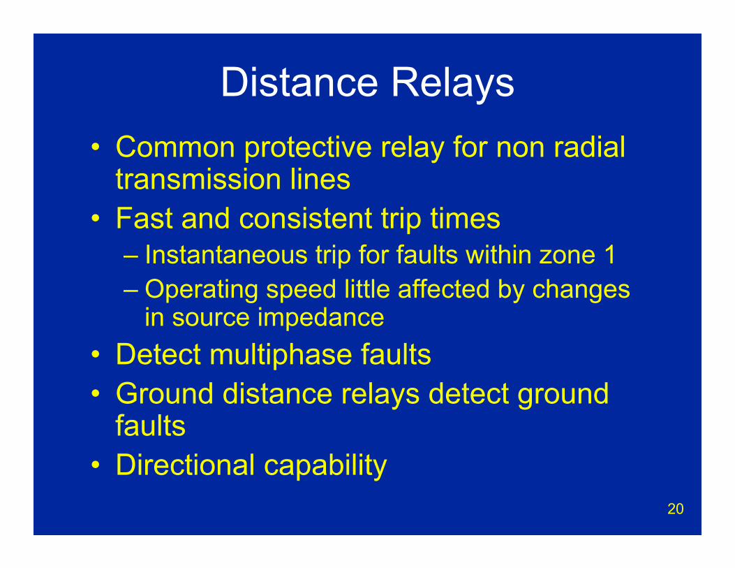
20
Distance Relays• Common protective relay for non radial
transmission lines• Fast and consistent trip times
– Instantaneous trip for faults within zone 1– Operating speed little affected by changes
in source impedance• Detect multiphase faults• Ground distance relays detect ground
faults• Directional capability
21
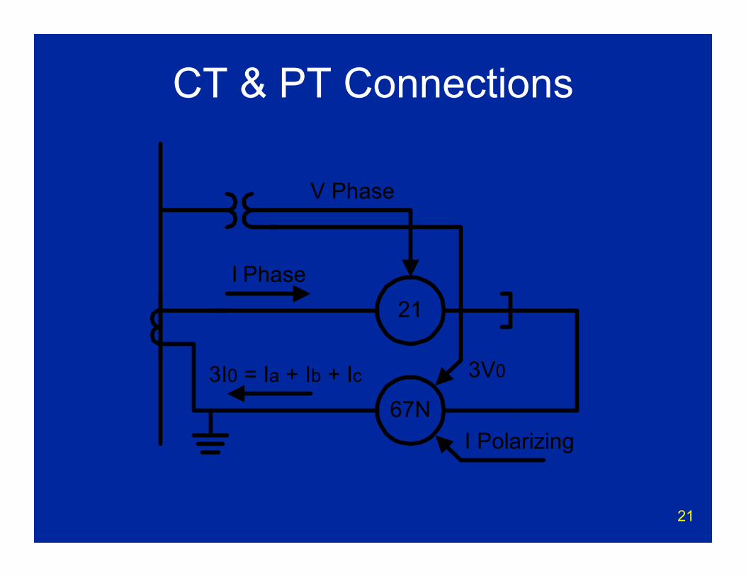
CT & PT Connections
21
67N
I Phase
3I0 = Ia + Ib + Ic 3V0
V Phase
I Polarizing
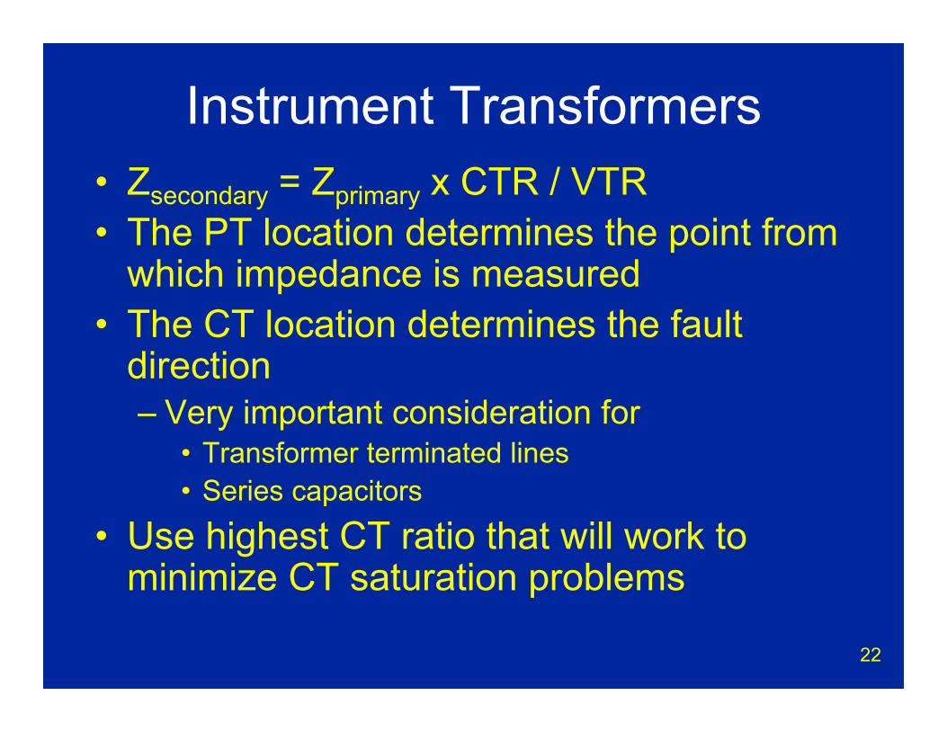
22
Instrument Transformers• Zsecondary = Zprimary x CTR / VTR• The PT location determines the point from
which impedance is measured• The CT location determines the fault
direction– Very important consideration for
• Transformer terminated lines• Series capacitors
• Use highest CT ratio that will work to minimize CT saturation problems
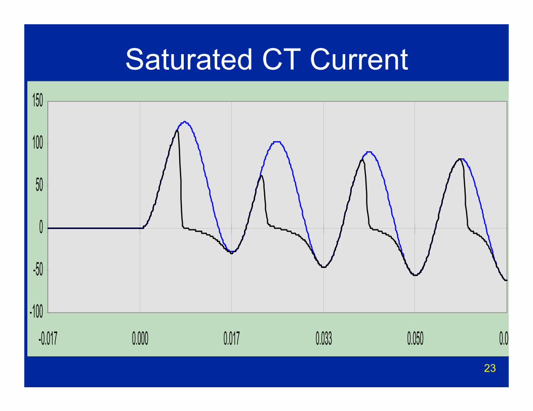
23
Saturated CT Current
-100
-50
0
50
100
150
-0.017 0.000 0.017 0.033 0.050 0.06
24
Original Distance Relay• True impedance characteristic
– Circular characteristic concentric to RX axis• Required separate directional element• Balance beam construction
– Similar to teeter totter– Voltage coil offered restraint– Current coil offered operation
• Westinghouse HZ– Later variation allowed for an offset circle
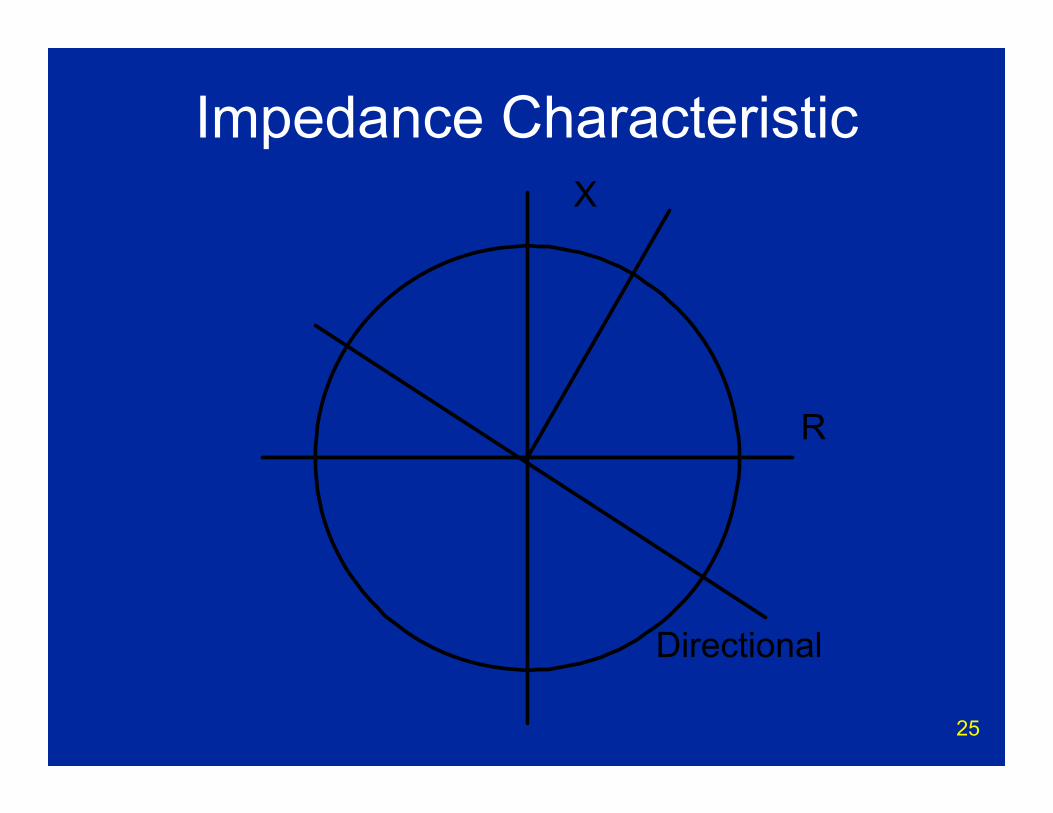
25
Impedance Characteristic
R
X
Directional

26
mho Characteristic• Most common distance element in use• Circular characteristic
– Passes through RX origin– No extra directional element required
• Maximum torque angle, MTA, usually set at line angle, ∠θ °– MTA is diameter of circle
• Different techniques used to provide full fault detection depending on relay type– Relay may also provide some or full
protection for ground faults
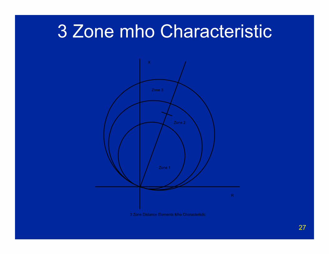
27
3 Zone mho CharacteristicX
R
Zone 1
Zone 2
Zone 3
3 Zone Distance Elements Mho Characteristic
28
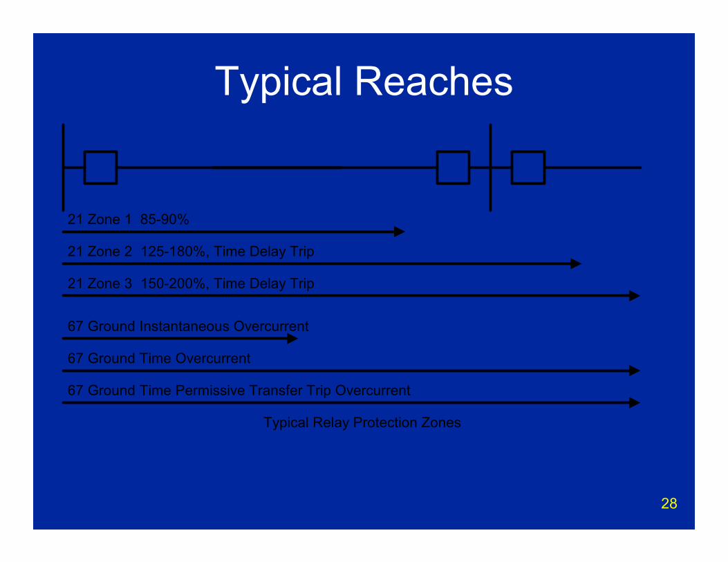
Typical Reaches
21 Zone 1 85-90%
21 Zone 2 125-180%, Time Delay Trip
21 Zone 3 150-200%, Time Delay Trip
Typical Relay Protection Zones
67 Ground Instantaneous Overcurrent
67 Ground Time Overcurrent
67 Ground Time Permissive Transfer Trip Overcurrent
29
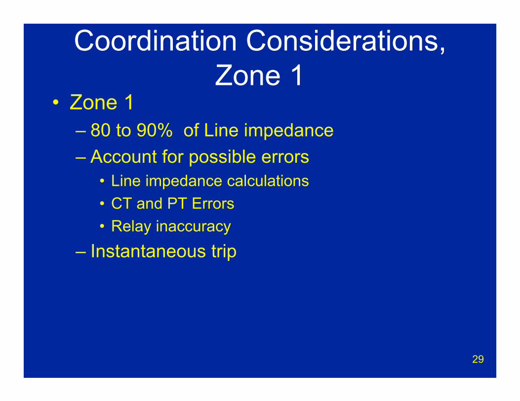
Coordination Considerations, Zone 1
• Zone 1– 80 to 90% of Line impedance– Account for possible errors
• Line impedance calculations• CT and PT Errors• Relay inaccuracy
– Instantaneous trip

30
Coordination Considerations• Zone 2
– 125% or more of line impedance• Consider strong line out of service• Consider lengths of lines at next substation
– Time Delay Trip• > 0.25 seconds (15 cycles)• Greater than BFR clearing time at remote bus• Must be slower if relay overreaches remote zone
2’s.– Also consider load encroachment– Zone 2 may be used with permissive
overreach transfer trip w/o time delay
31
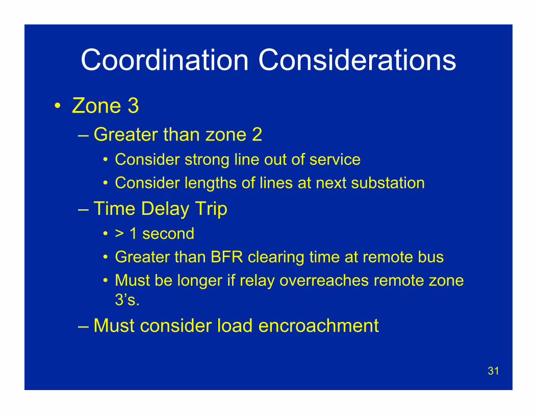
Coordination Considerations• Zone 3
– Greater than zone 2• Consider strong line out of service• Consider lengths of lines at next substation
– Time Delay Trip• > 1 second• Greater than BFR clearing time at remote bus• Must be longer if relay overreaches remote zone
3’s.– Must consider load encroachment

32
Coordination Considerations• Zone 3 Special Applications
– Starter element for zones 1 and 2– Provides current reversal logic for permissive
transfer trip (reversed)– May be reversed to provide breaker failure
protection– Characteristic may include origin for current
only tripping– May not be used
33
Problems for Distance Relays• Fault in front of relay• Apparent Impedance• Load encroachment• Fault resistance• Series compensated lines• Power swings
34
3 Phase Fault in Front of Relay• No voltage to make impedance
measurement-use a potential memory circuit in distance relay
• Use a non-directional, instantaneous overcurrent relay (50-Dead line fault relay)
• Utilize switch into fault logic– Allow zone 2 instantaneous trip

35
Apparent Impedance• 3 Terminal lines with apparent
impedance• Fault resistance also looks like an
apparent impedance • Most critical with very short or
unbalanced legs• Results in
– Short zone 1 reaches– Long zone 2 reaches and time delays
• Pilot protection may be required

36
Apparent ImpedanceBus A Bus BZa = 1 ohm
Ia = 1
Zb = 1
Ib = 1
Z apparent @Bus A = Za +
ZcIc/Ia= 3 Ohms
Apparent Impedance
Ic = Ia + Ib = 2 Zc = 1
Bus C
37
Coordination Considerations• Zone 1
– Set to 85 % of actual impedance to nearest terminal
• Zone 2– Set to 125 + % of apparent impedance to
most distant terminal– Zone 2 time delay must coordinate with all
downstream relays• Zone 3
– Back up for zone 2
38
Load Encroachment• Z Load = kV2 / MVA
– Long lines present biggest challenge– Heavy load may enter relay characteristic
• Serious problem in August, 2003 East Coast Disturbance
• NERC Loading Criteria– 150 % of emergency line load rating – Use reduced voltage (85 %)– 30° Line Angle
• Z @ 30° = Z @ MTA cos (∠MTA° -∠30° ) for mho characteristic
39
Load Encroachment• NERC Loading Criteria
– Applies to zone 2 and zone 3 phase distance• Other overreaching phase distance elements
– All transmission lines > 200 kV– Many transmission lines > 100 kV
• Solutions– Don’t use conventional zone 3 element– Use lens characteristic– Use blinders or quadrilateral characteristic– Tilt mho characteristic toward X axis– Utilize special relay load encroachment
characteristic

40
Load EncroachmentX
R
Zone 1
Zone 2
Zone 3
Load Consideration with Distance Relays
LoadArea

41
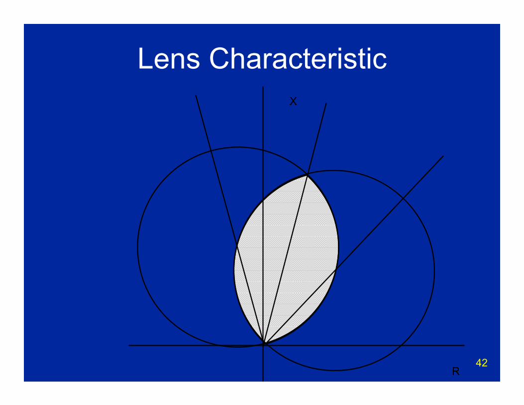
Lens Characteristic• Ideal for longer transmission lines• More immunity to load encroachment• Less fault resistance coverage• Generated by merging the common area
between two mho elements
42
Lens Characteristic
43
Tomato Characteristic• May be used as an external out of step
blocking characteristic• Reaches set greater than the tripping
elements• Generated by combining the total area of
two mho elements

44
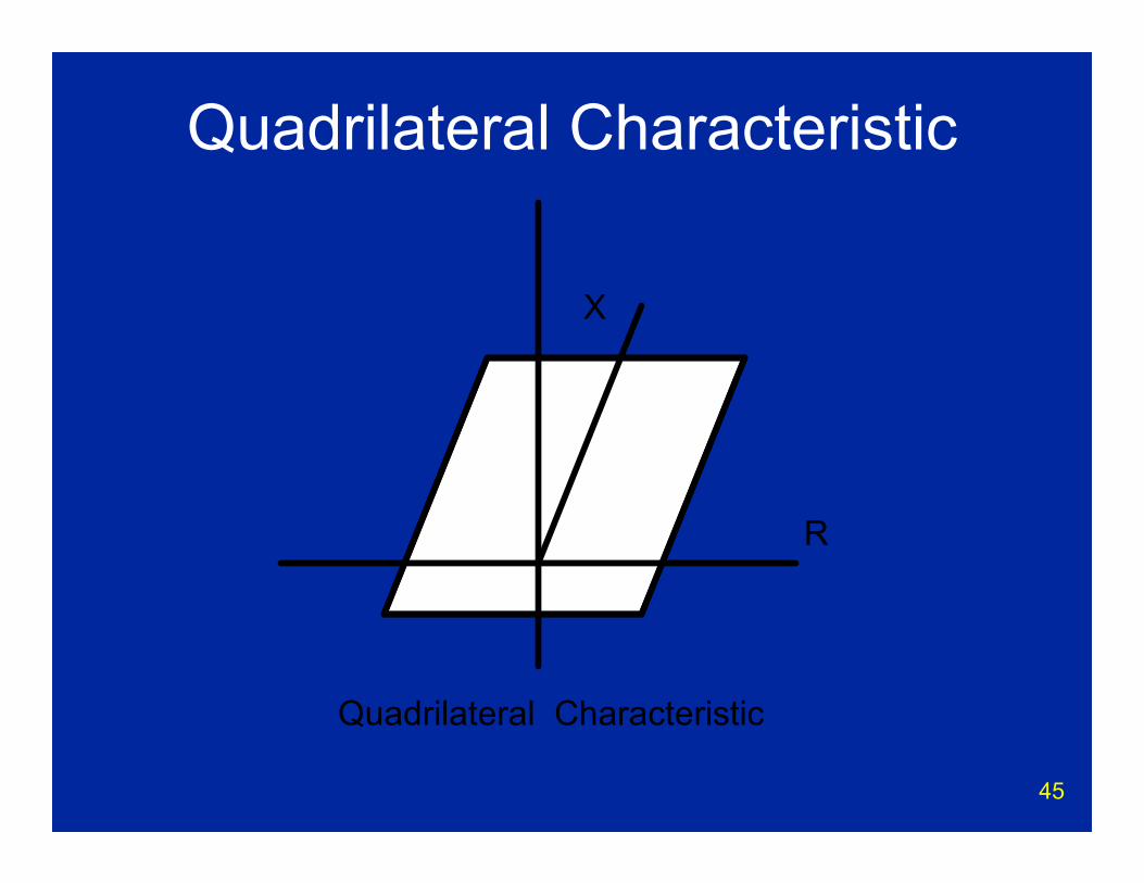
Quadrilateral Characteristic• High level of freedom in settings• Blinders on left and right can be moved in
or out– More immunity to load encroachment (in)– More fault resistance coverage (out)
• Generated by the common area between– Left and right blinders– Below reactance element– Above directional element
45
Quadrilateral Characteristic
R
X
Quadrilateral Characteristic
46
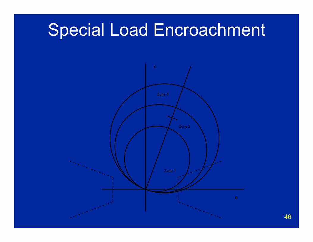
Special Load Encroachment
X
R
Zone 1
Zone 2
Zone 4
47
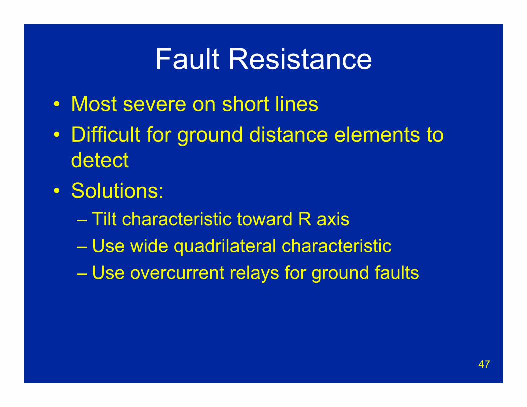
Fault Resistance• Most severe on short lines• Difficult for ground distance elements to
detect• Solutions:
– Tilt characteristic toward R axis– Use wide quadrilateral characteristic– Use overcurrent relays for ground faults
48
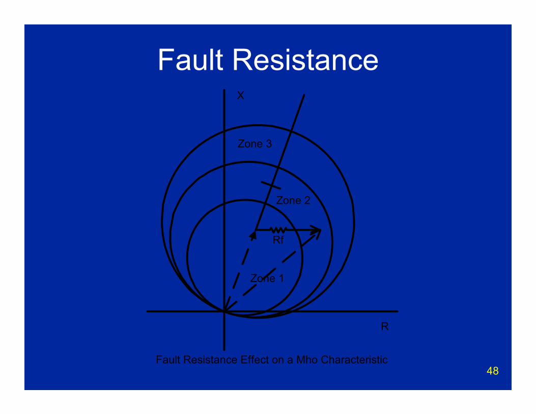
Fault ResistanceX
R
Zone 1
Zone 2
Zone 3
Fault Resistance Effect on a Mho Characteristic
Rf

49
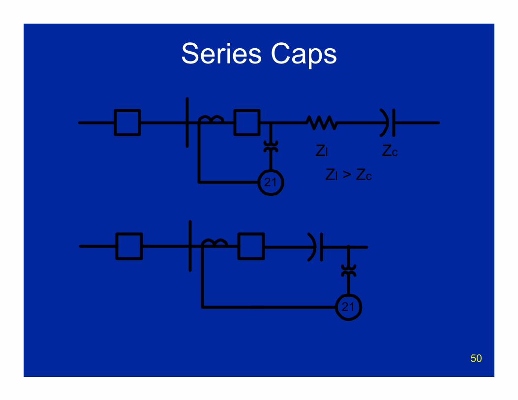
Series Compensated Lines• Series caps added to increase load
transfers– Electrically shorten line
• Negative inductance• Difficult problem for distance relays• Application depends upon location of
capacitors
50
Series Caps
21
21
Zl Zc
Zl > Zc
51
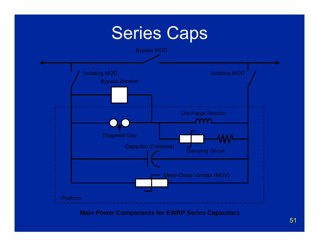
Series CapsBypass MOD
Bypass Breaker
Discharge Reactor
Damping Circuit
Metal-Oxide Varistor (MOV)
Capacitor (Fuseless)
Triggered Gap
Isolating MOD Isolating MOD
Platform
Main Power Components for EWRP Series Capacitors
52
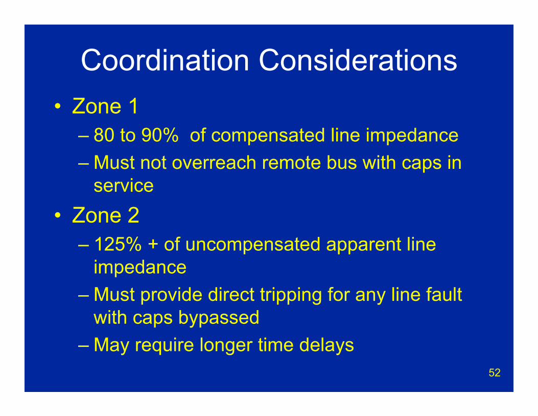
Coordination Considerations • Zone 1
– 80 to 90% of compensated line impedance– Must not overreach remote bus with caps in
service• Zone 2
– 125% + of uncompensated apparent line impedance
– Must provide direct tripping for any line fault with caps bypassed
– May require longer time delays
53
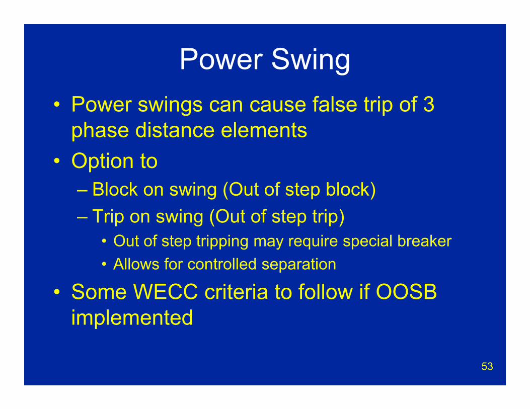
Power Swing• Power swings can cause false trip of 3
phase distance elements• Option to
– Block on swing (Out of step block)– Trip on swing (Out of step trip)
• Out of step tripping may require special breaker• Allows for controlled separation
• Some WECC criteria to follow if OOSB implemented
54
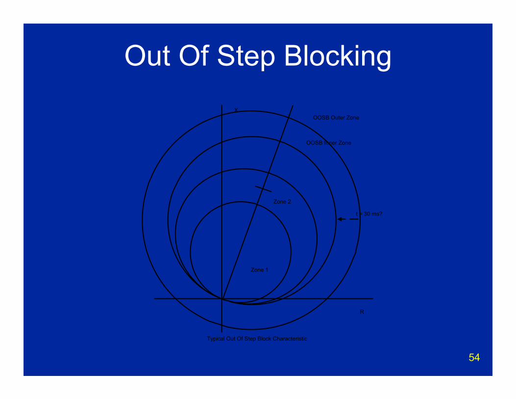
Out Of Step BlockingX
R
Zone 1
Zone 2
Typical Out Of Step Block Characteristic
OOSB Outer Zone
OOSB Inner Zone
t = 30 ms?

55
Ground Distance Protection
and Kn(21G)
56
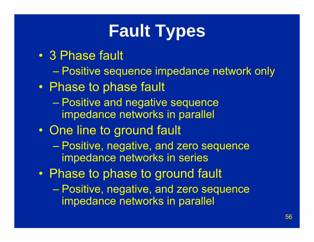
Fault Types• 3 Phase fault
– Positive sequence impedance network only• Phase to phase fault
– Positive and negative sequence impedance networks in parallel
• One line to ground fault– Positive, negative, and zero sequence
impedance networks in series• Phase to phase to ground fault
– Positive, negative, and zero sequence impedance networks in parallel

57
Sequence Networks
58
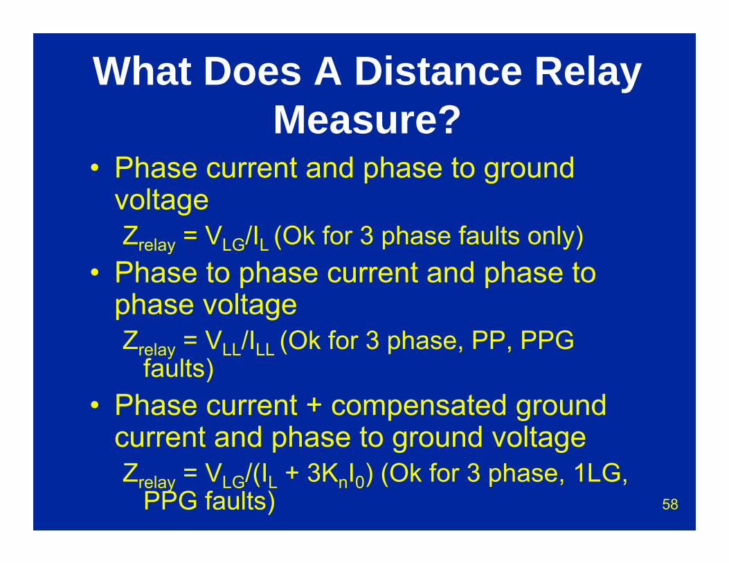
What Does A Distance Relay Measure?
• Phase current and phase to ground voltageZrelay = VLG/IL (Ok for 3 phase faults only)
• Phase to phase current and phase to phase voltageZrelay = VLL/ILL (Ok for 3 phase, PP, PPG
faults)• Phase current + compensated ground
current and phase to ground voltageZrelay = VLG/(IL + 3KnI0) (Ok for 3 phase, 1LG,
PPG faults)
59
Kn - Why?• Using phase/phase or phase/ground
quantities does not give proper reach measurement for 1LG fault
• Using zero sequence quantities gives the zero sequence source impedance, not the line impedance
• Current compensation (Kn) does work for ground faults
• Voltage compensation could also be used but is less common
60
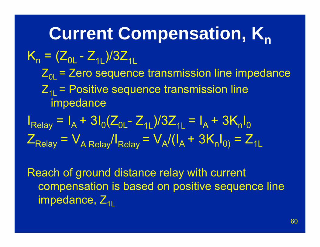
Current Compensation, KnKn = (Z0L - Z1L)/3Z1L
Z0L = Zero sequence transmission line impedanceZ1L = Positive sequence transmission line
impedanceIRelay = IA + 3I0(Z0L- Z1L)/3Z1L = IA + 3KnI0
ZRelay = VA Relay/IRelay = VA/(IA + 3KnI0) = Z1L
Reach of ground distance relay with current compensation is based on positive sequence line impedance, Z1L
61
Current Compensation, Kn• Current compensation (Kn) does work for
ground faults.• Kn = (Z0L – Z1L)/3Z1
– Kn may be a scalar quantity or a vector quantity with both magnitude and angle
• Mutual impedance coupling from parallel lines can cause a ground distance relay to overreach or underreach, depending upon ground fault location
• Mutual impedance coupling can provide incorrect fault location values for ground faults
62
Ground Fault Protection
(67N)
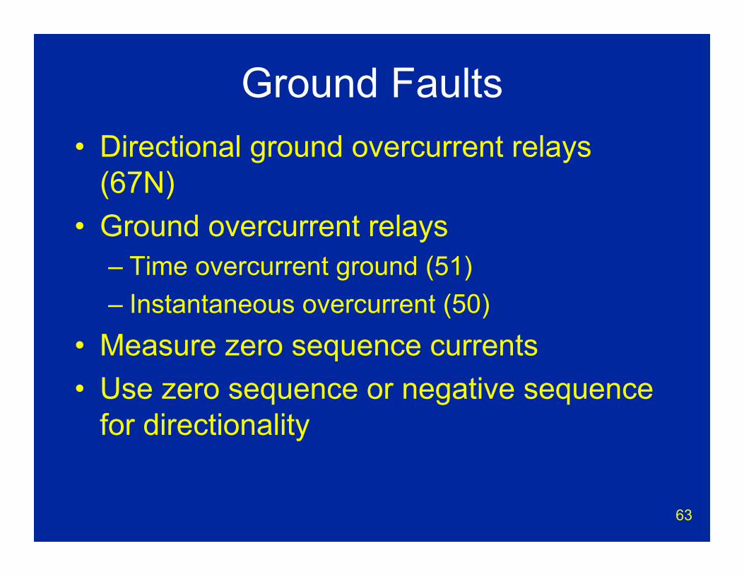
63
Ground Faults• Directional ground overcurrent relays
(67N)• Ground overcurrent relays
– Time overcurrent ground (51)– Instantaneous overcurrent (50)
• Measure zero sequence currents• Use zero sequence or negative sequence
for directionality
64
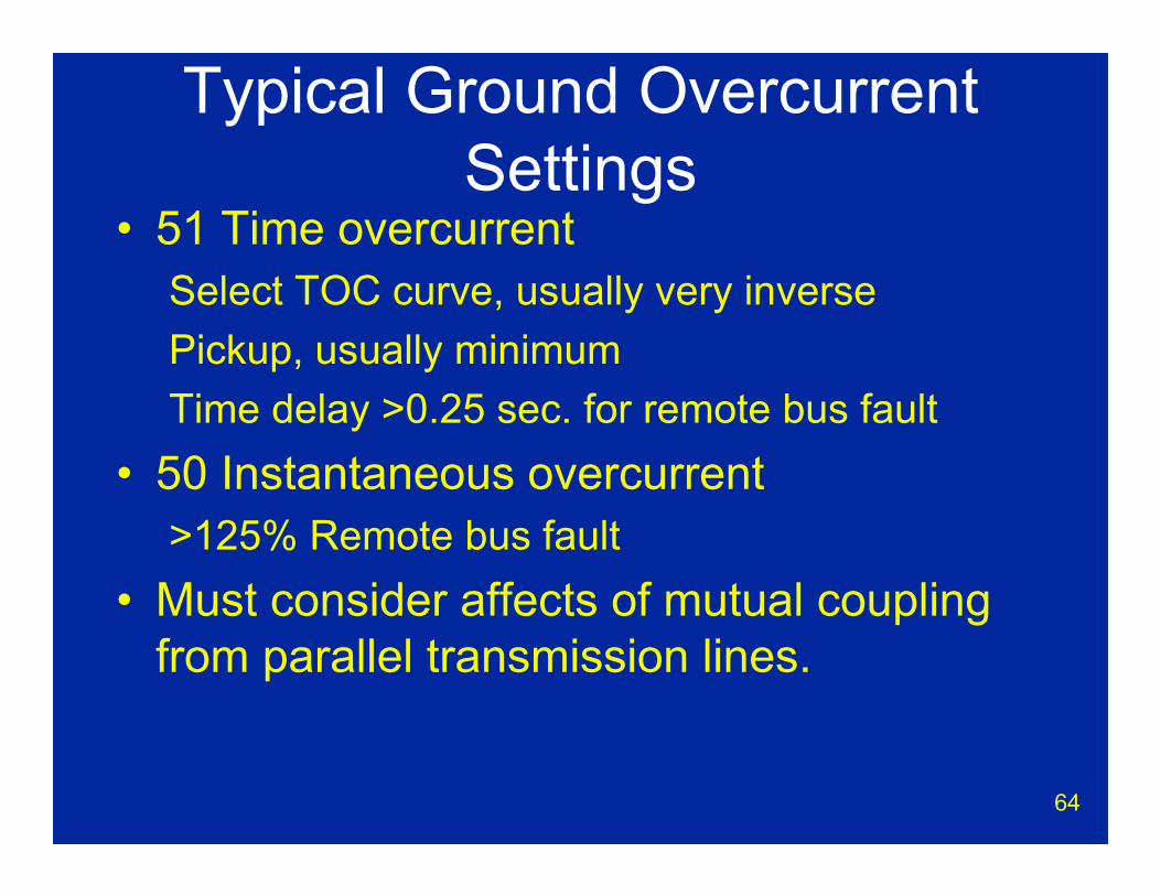
Typical Ground Overcurrent Settings
• 51 Time overcurrentSelect TOC curve, usually very inversePickup, usually minimumTime delay >0.25 sec. for remote bus fault
• 50 Instantaneous overcurrent>125% Remote bus fault
• Must consider affects of mutual coupling from parallel transmission lines.
65
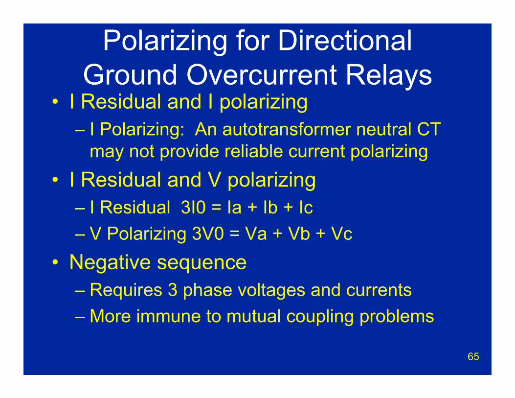
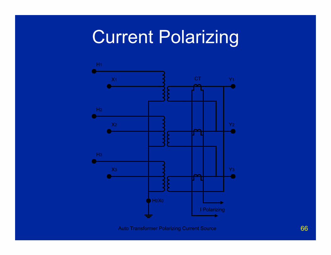
Polarizing for Directional Ground Overcurrent Relays
• I Residual and I polarizing– I Polarizing: An autotransformer neutral CT
may not provide reliable current polarizing• I Residual and V polarizing
– I Residual 3I0 = Ia + Ib + Ic– V Polarizing 3V0 = Va + Vb + Vc
• Negative sequence – Requires 3 phase voltages and currents– More immune to mutual coupling problems
66
Current Polarizing
I Polarizing
Auto Transformer Polarizing Current Source
CT
H1
X1
H3
X3
H2
X2
Y1
Y2
Y3
H0X0
67
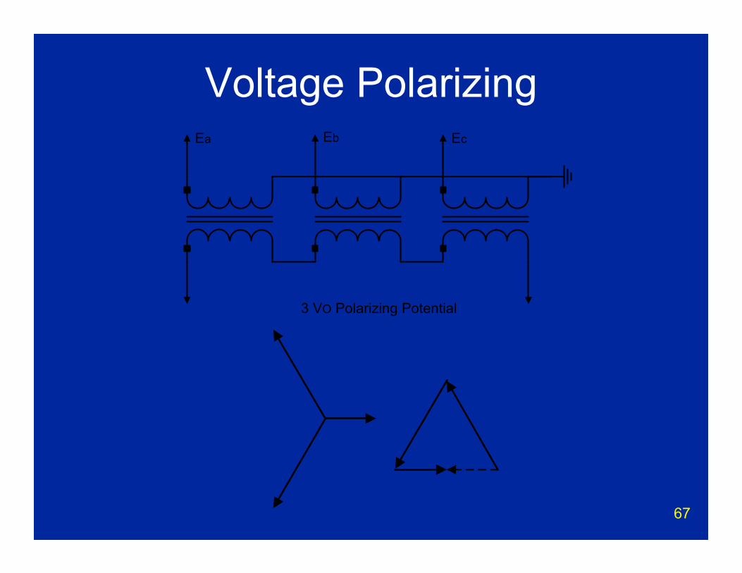
Voltage Polarizing
3 VO Polarizing Potential
Ea Eb Ec

68
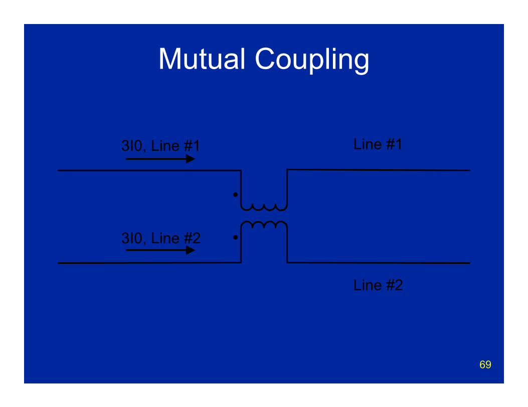
Mutual Coupling• Transformer affect between parallel lines
– Inversely proportional to distance between lines
• Only affects zero sequence current• Will affect magnitude of ground currents• Will affect reach of ground distance relays
69
Mutual Coupling
Line #1
Line #2
3I0, Line #1
3I0, Line #2
70
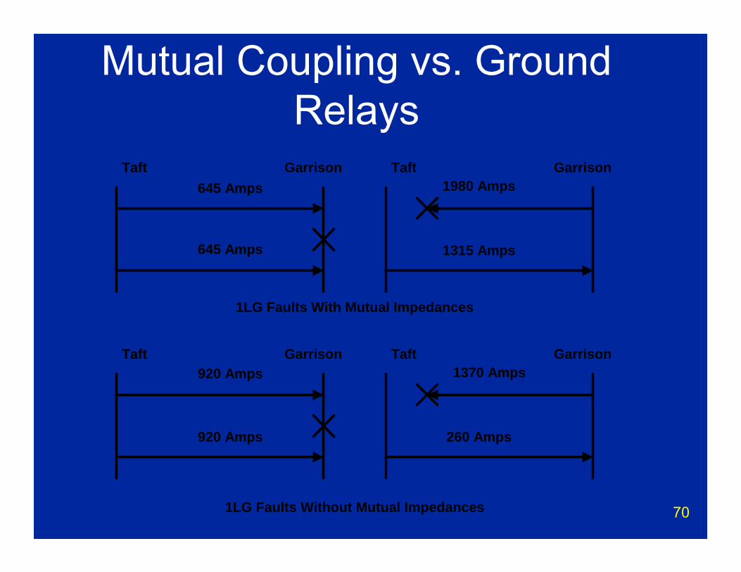
Mutual Coupling vs. Ground Relays
Taft
Taft
645 Amps
1315 Amps645 Amps
1980 Amps
920 Amps
260 Amps920 Amps
1370 Amps
1LG Faults With Mutual Impedances
1LG Faults Without Mutual Impedances
Garrison
Garrison
Taft Garrison
Taft Garrison

71
Other Line Protection Relays
72
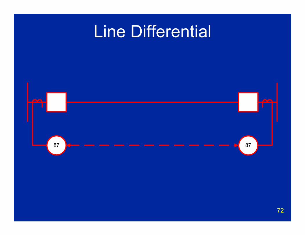
Line Differential
87 87
73
Line Differential Relays• Compare current magnitudes, phase, etc.
at each line terminal• Communicate information between relays• Internal/external fault? Trip/no trip?• Communications dependant!• Changes in communications paths or
channel delays can cause potential problems

74
Phase Comparison• Compares phase relationship at terminals• 100% Channel dependant
– Looped channels can cause false trips• Nondirectional overcurrent on channel
failure• Immune to swings, load, series caps• Single pole capability

75
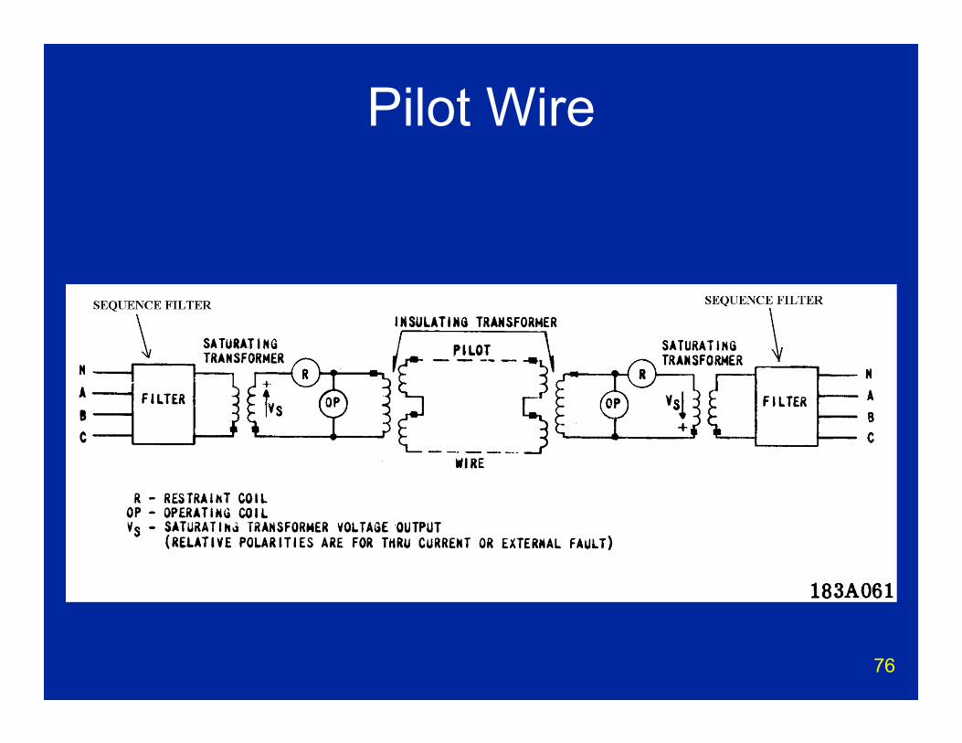
Pilot Wire• Common on power house lines• Uses metallic twisted pair
– Problems if commercial line used– Requires isolation transformers and protection
on pilot wire• Nondirectional overcurrent on pilot failure• Newer versions use fiber or radio• Generally limited to short lines if metallic
twisted pair is used
76
Pilot Wire
77
Current Differential• Similar to phase comparison• Channel failure?
– Distance relay backup or– Non directional overcurrent backup or– No backup – must add separate back up
relay• Many channel options
– Changes in channel delays may cause problems
– Care required in setting up digital channels
78
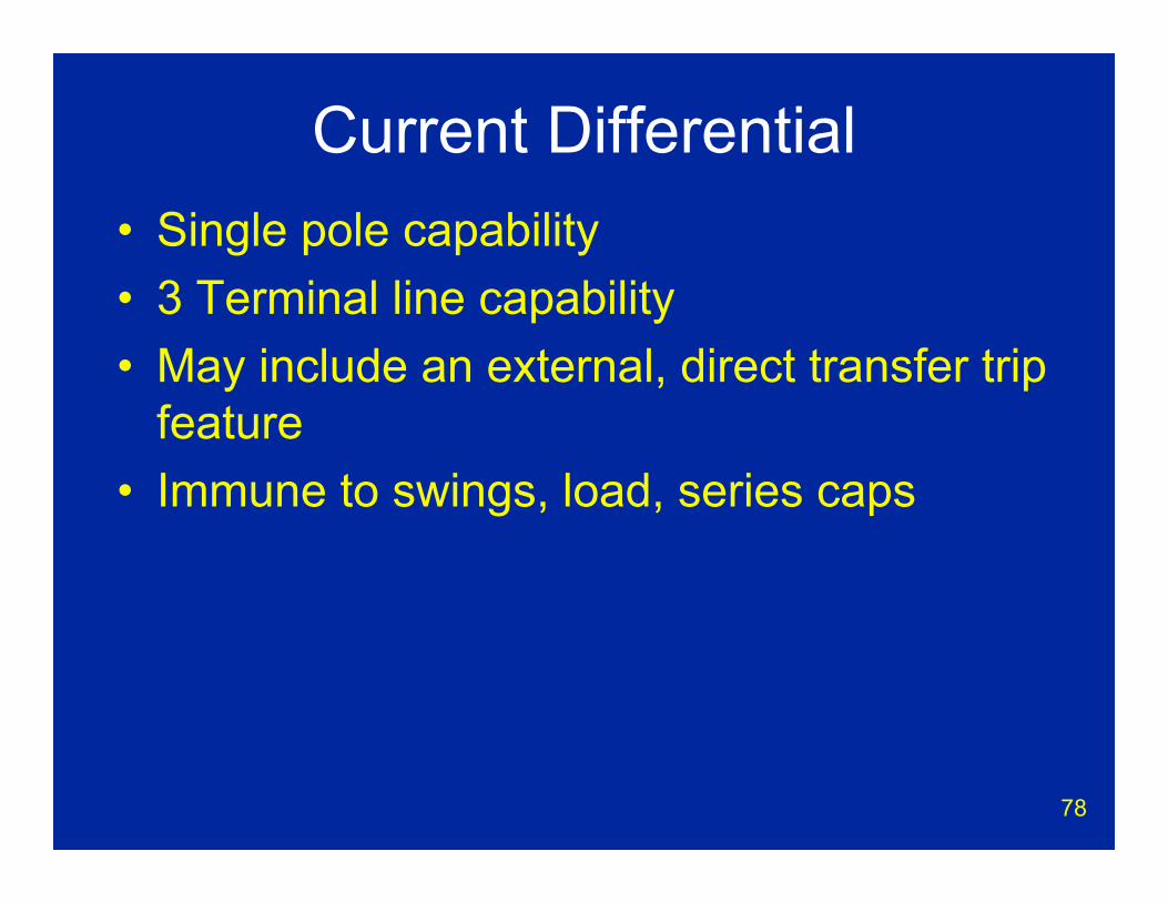
Current Differential• Single pole capability• 3 Terminal line capability• May include an external, direct transfer trip
feature • Immune to swings, load, series caps

79
Transfer Trip
80
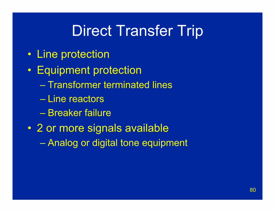
Direct Transfer Trip• Line protection• Equipment protection
– Transformer terminated lines– Line reactors– Breaker failure
• 2 or more signals available– Analog or digital tone equipment
81
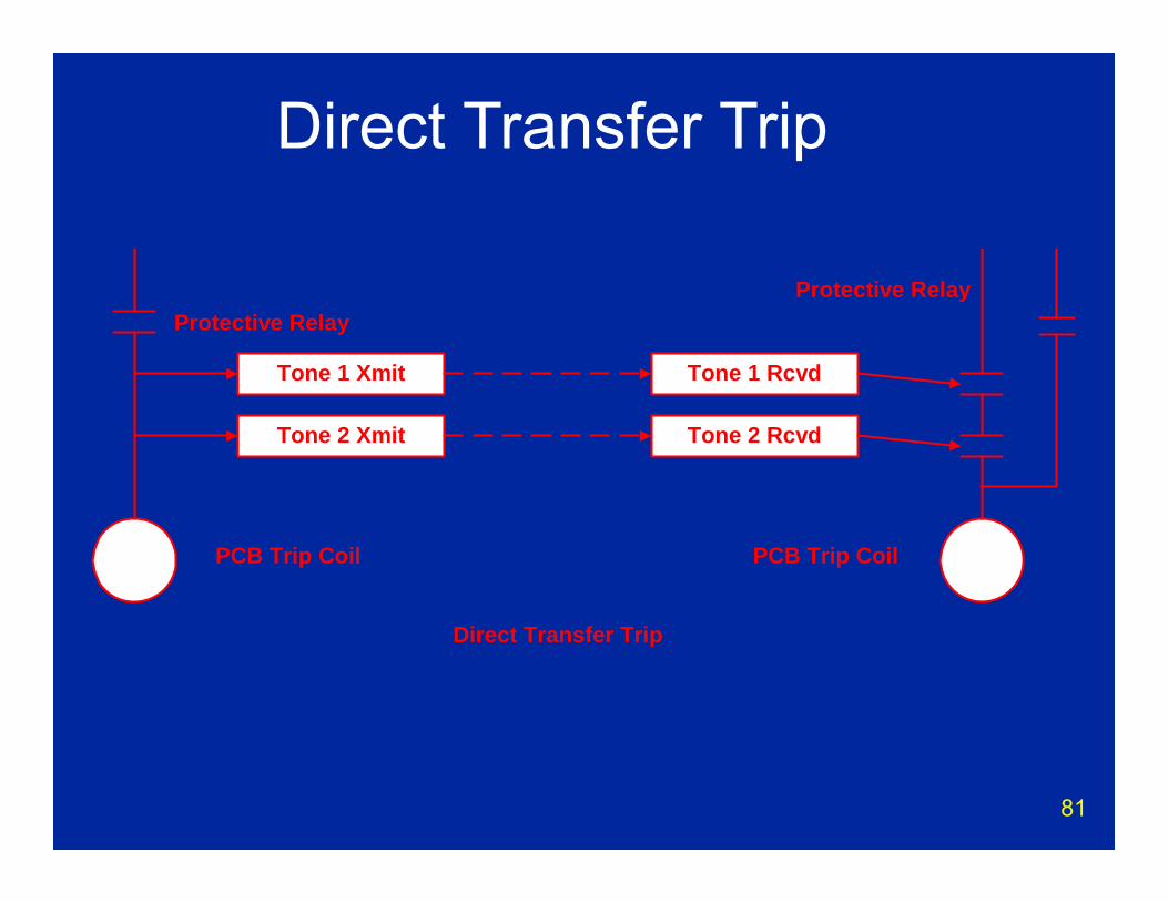
Tone 1 Xmit
Tone 2 Xmit
PCB Trip Coil PCB Trip Coil
Tone 1 Rcvd
Tone 2 Rcvd
Direct Transfer Trip
Protective RelayProtective Relay
Direct Transfer Trip
82
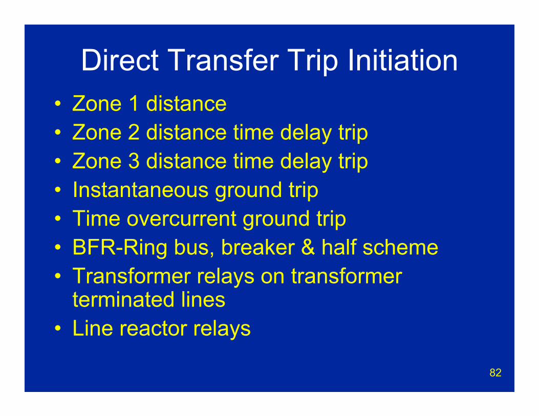
Direct Transfer Trip Initiation• Zone 1 distance• Zone 2 distance time delay trip• Zone 3 distance time delay trip• Instantaneous ground trip• Time overcurrent ground trip• BFR-Ring bus, breaker & half scheme• Transformer relays on transformer
terminated lines• Line reactor relays
83
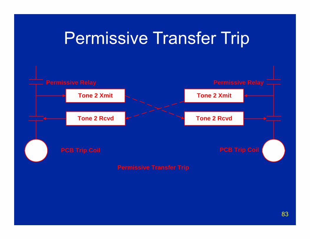
Tone 2 Xmit
Tone 2 Rcvd
Permissive Relay
PCB Trip Coil PCB Trip Coil
Tone 2 Xmit
Tone 2 Rcvd
Permissive Transfer Trip
Permissive Relay
Permissive Transfer Trip
84
Permissive Keying• Zone 2 instantaneous• Permissive overcurrent ground (very
sensitive setting)• PCB 52/b switch• Current reversal can cause problems
85
PRT Current Reversal
A
C D
B
Ib
Id
Ia
Ic
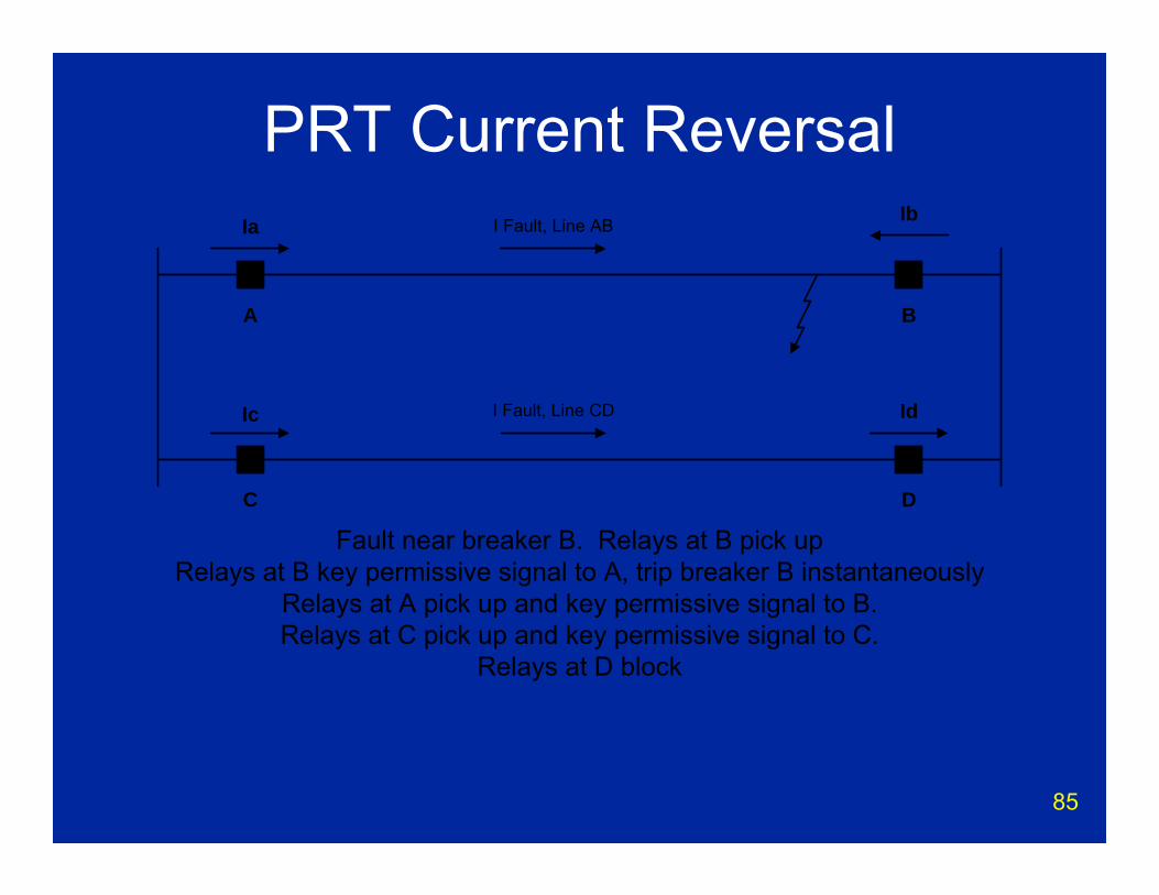
Fault near breaker B. Relays at B pick upRelays at B key permissive signal to A, trip breaker B instantaneously
Relays at A pick up and key permissive signal to B.Relays at C pick up and key permissive signal to C.
Relays at D block
I Fault, Line AB
I Fault, Line CD
86
PRT Current Reversal
A
C D
B
Id
Ia
Ic
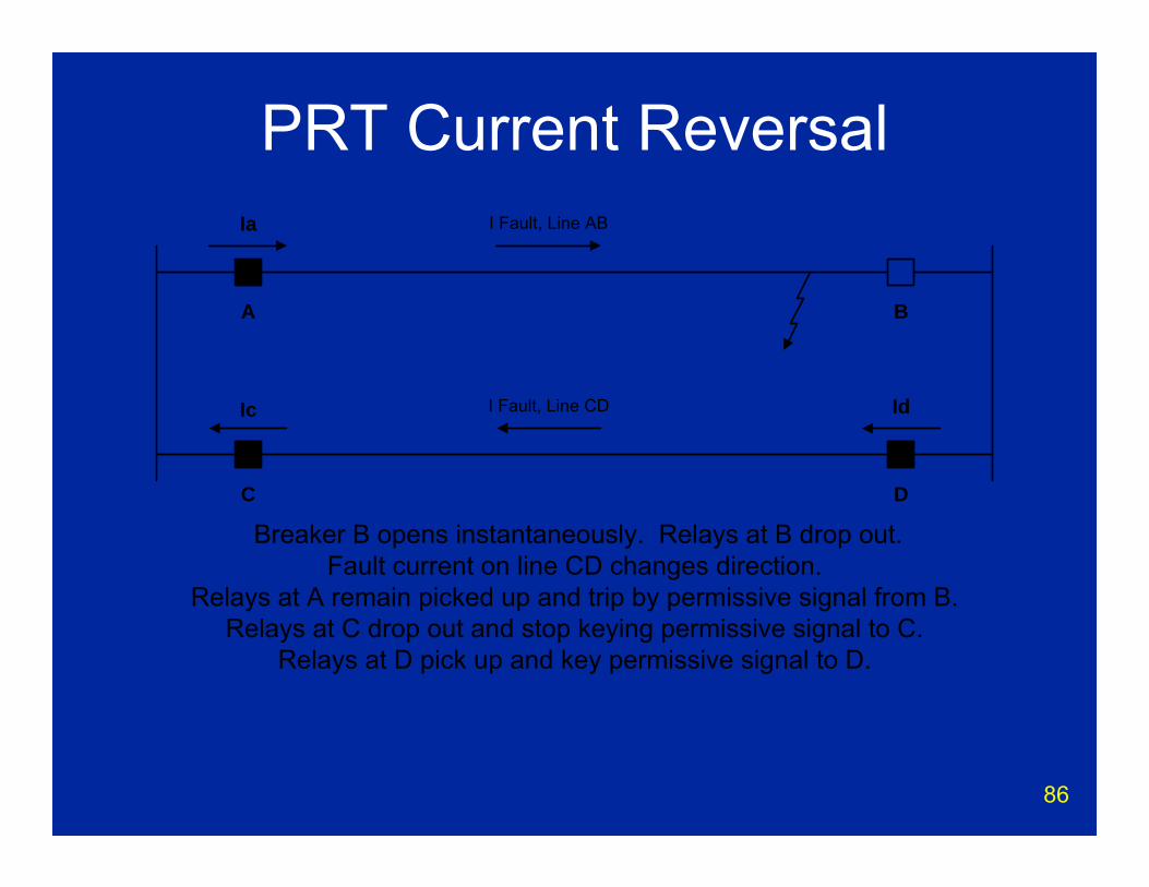
Breaker B opens instantaneously. Relays at B drop out.Fault current on line CD changes direction.
Relays at A remain picked up and trip by permissive signal from B.Relays at C drop out and stop keying permissive signal to C.
Relays at D pick up and key permissive signal to D.
I Fault, Line AB
I Fault, Line CD

87
Directional Comparison Blocking
• Overreaching relays• Delay for channel time• Channel failure can allow overtrip• Often used with “On/Off” carrier

88
Block Xmit
Block Rcvd
PCB Trip Coil PCB Trip Coil
Block Xmit
Block Rcvd
Directional Comparison Blocking Scheme
Time DelayTime Delay
ForwardRelay
ReverseRelay
ReverseRelay
ForwardRelay
TDTD
Directional Comparison
89
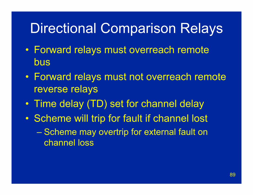
Directional Comparison Relays• Forward relays must overreach remote
bus• Forward relays must not overreach remote
reverse relays• Time delay (TD) set for channel delay• Scheme will trip for fault if channel lost
– Scheme may overtrip for external fault on channel loss
90
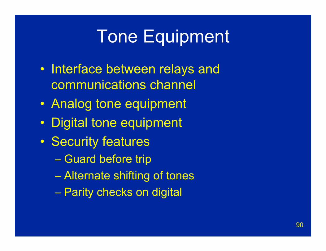
Tone Equipment
• Interface between relays and communications channel
• Analog tone equipment• Digital tone equipment• Security features
– Guard before trip– Alternate shifting of tones– Parity checks on digital
91
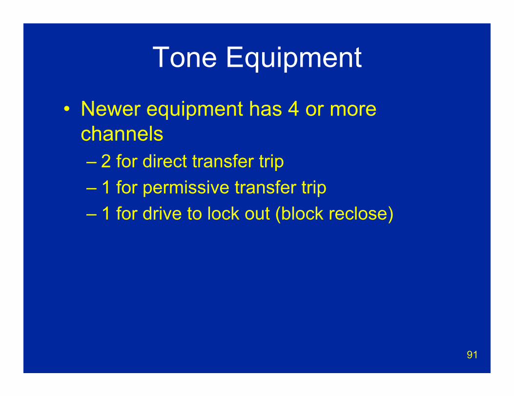
Tone Equipment
• Newer equipment has 4 or more channels– 2 for direct transfer trip– 1 for permissive transfer trip– 1 for drive to lock out (block reclose)
92
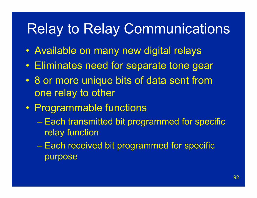
Relay to Relay Communications• Available on many new digital relays• Eliminates need for separate tone gear• 8 or more unique bits of data sent from
one relay to other• Programmable functions
– Each transmitted bit programmed for specific relay function
– Each received bit programmed for specific purpose
93
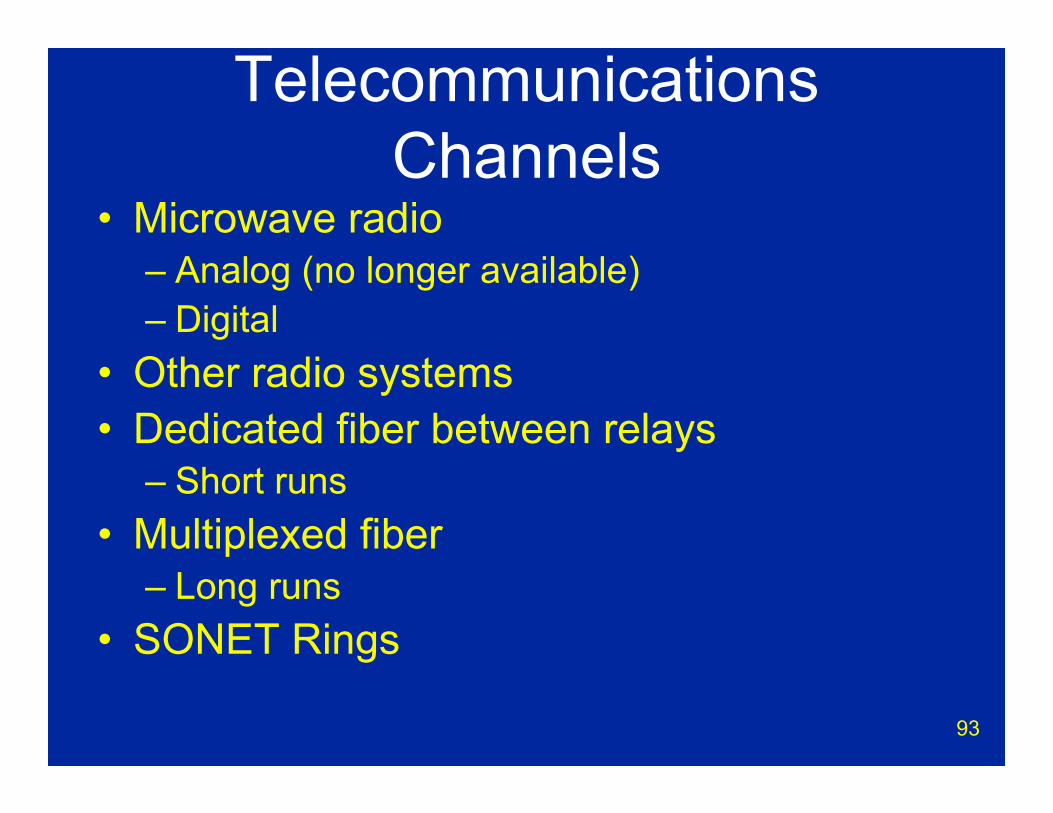
Telecommunications Channels
• Microwave radio– Analog (no longer available)– Digital
• Other radio systems• Dedicated fiber between relays
– Short runs• Multiplexed fiber
– Long runs• SONET Rings
94
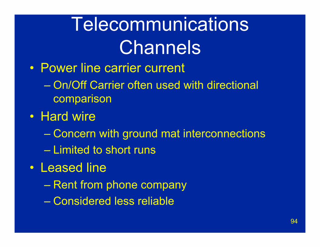
Telecommunications Channels
• Power line carrier current– On/Off Carrier often used with directional
comparison• Hard wire
– Concern with ground mat interconnections– Limited to short runs
• Leased line– Rent from phone company– Considered less reliable
95
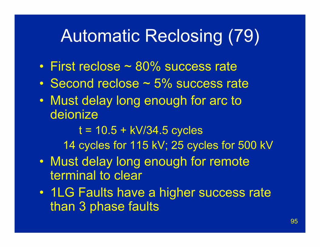
Automatic Reclosing (79)• First reclose ~ 80% success rate• Second reclose ~ 5% success rate• Must delay long enough for arc to
deionizet = 10.5 + kV/34.5 cycles
14 cycles for 115 kV; 25 cycles for 500 kV• Must delay long enough for remote
terminal to clear• 1LG Faults have a higher success rate
than 3 phase faults
96
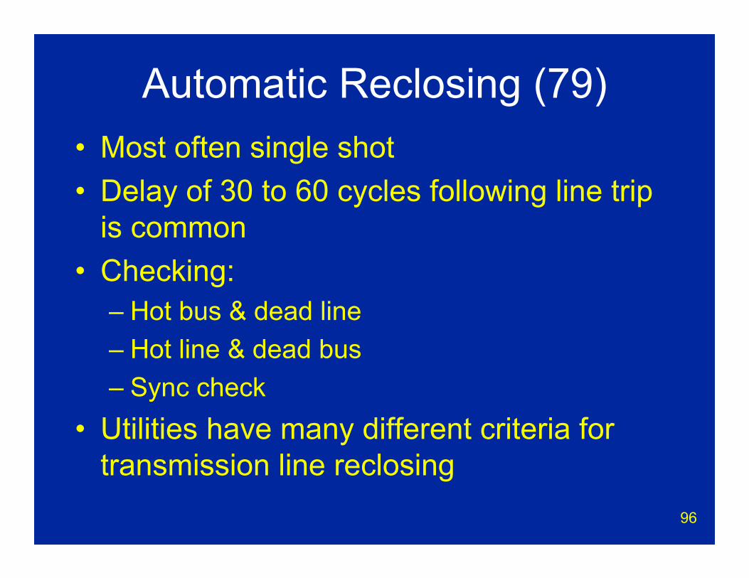
Automatic Reclosing (79)• Most often single shot• Delay of 30 to 60 cycles following line trip
is common• Checking:
– Hot bus & dead line– Hot line & dead bus– Sync check
• Utilities have many different criteria for transmission line reclosing
97
More on Reclosing• Only reclose for one line to ground faults • Block reclose for time delay trip (pilot
schemes)• Never reclose on power house lines• Block reclosing for transformer fault on
transformer terminated lines• Block reclosing for bus faults• Block reclosing for BFR• Do not use them
98
Breaker Failure Relay(50BF)
99
Breaker Failure• Stuck breaker is a severe impact to
system stability on transmission systems• Breaker failure relays are recommended
by NERC for transmission systems operated above 100 kV
• BFRs are not required to be redundant by NERC
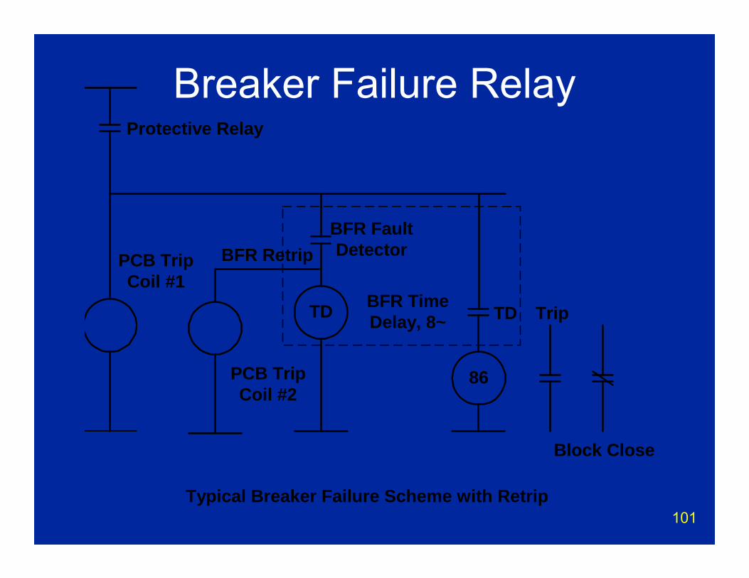
100
Breaker Failure Relays1. Fault on line2. Normal protective relays detect fault and
send trip to breaker.3. Breaker does not trip.4. BFR Fault detectors picked up.5. BFR Time delay times out (8 cycles)6. Clear house (open everything to isolate
failed breaker)
101
Breaker Failure Relay
Typical Breaker Failure Scheme with Retrip
BFR FaultDetectorPCB Trip
Coil #1TD
Protective Relay
86
Trip
Block Close
TD
PCB TripCoil #2
BFR Retrip
BFR TimeDelay, 8~
102
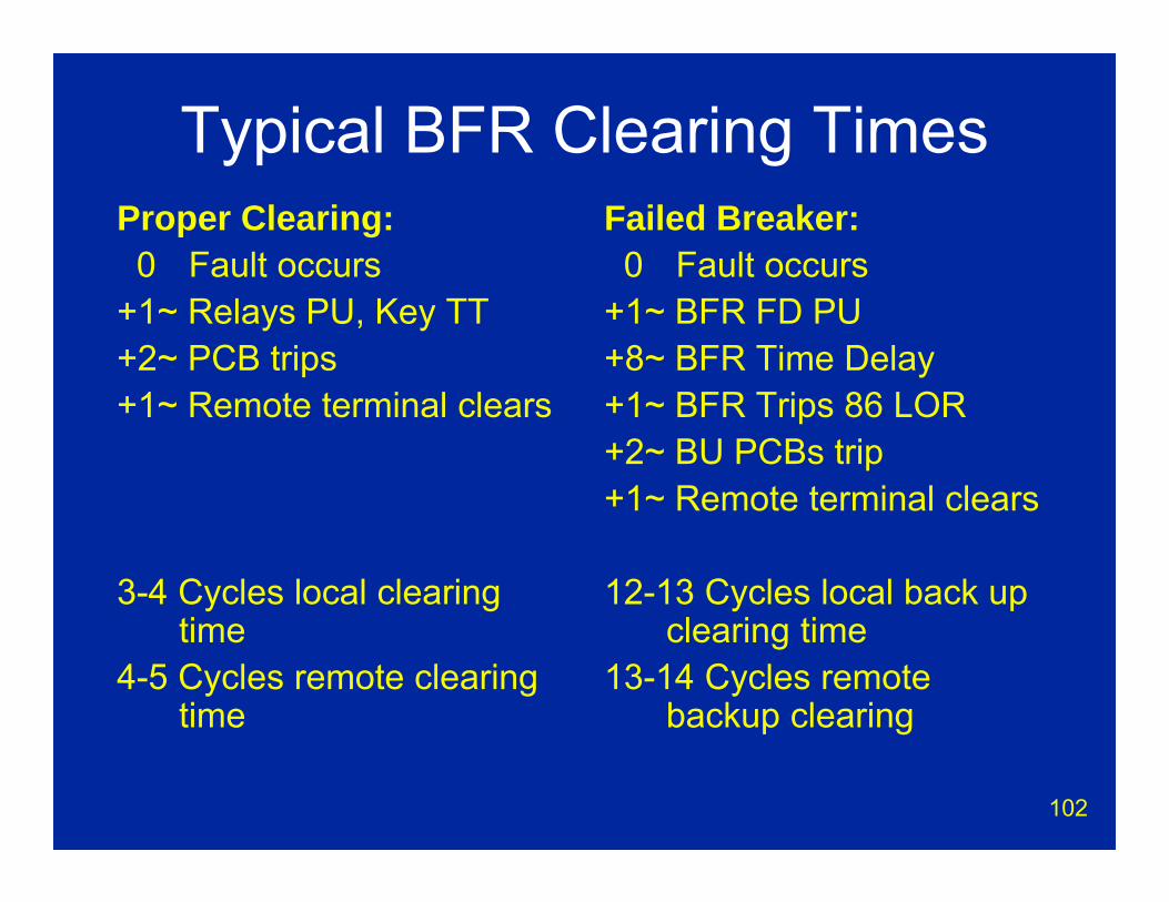
Typical BFR Clearing TimesProper Clearing:0 Fault occurs
+1~ Relays PU, Key TT+2~ PCB trips+1~ Remote terminal clears
3-4 Cycles local clearing time
4-5 Cycles remote clearing time
Failed Breaker:0 Fault occurs
+1~ BFR FD PU+8~ BFR Time Delay+1~ BFR Trips 86 LOR+2~ BU PCBs trip+1~ Remote terminal clears
12-13 Cycles local back up clearing time
13-14 Cycles remote backup clearing
103
Remedial Action Schemes (RAS)
aka: Special Protection Schemes

104
Remedial Action Schemes• Balance generation and loads• Maintain system stability• Prevent major problems (blackouts)• Prevent equipment damage• Allow system to be operated at higher
levels• Provide controlled islanding• Protect equipment and lines from thermal
overloads• Many WECC & NERC Requirements

105
Remedial Action Schemes• WECC Compliant RAS
– Fully redundant– Annual functional test– Changes, modifications and additions must be
approved by WECC• Non WECC RAS
– Does not need full redundancy– Local impacts only– Primarily to solve thermal overload problems
106
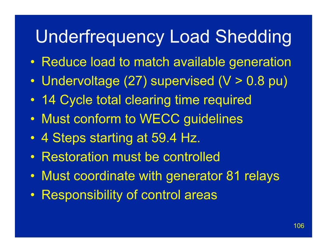
Underfrequency Load Shedding• Reduce load to match available generation• Undervoltage (27) supervised (V > 0.8 pu)• 14 Cycle total clearing time required• Must conform to WECC guidelines• 4 Steps starting at 59.4 Hz.• Restoration must be controlled• Must coordinate with generator 81 relays• Responsibility of control areas

107
Undervoltage Load Shedding• Detect 3 Phase undervoltage• Prevent voltage collapse• Sufficient time delay before tripping to ride
through minor disturbances• Must Conform to WECC Guidelines• Primarily installed West of Cascades
108
Generator Dropping• Trip generators for loss of load• Trip generators for loss of transmission
lines or paths– Prevent overloading
109
Reactive Switching• On loss of transmission lines
– Trip shunt reactors to increase voltage– Close shunt capacitors to compensate for loss
of reactive supplied by transmission lines– Close series capacitors to increase load
transfers– Utilize generator var output if possible– Static Var Compensators (SVC) provide high
speed adjustments
110
Direct Load Tripping• Provide high speed trip to shed load
– May use transfer trip – May use sensitive, fast underfrequency (81)
relay• Trip large industrial loads
111
Other RAS Schemes• Controlled islanding
– Force separation at know locations• Load brake resistor insertion
– Provide a resistive load to slow down acceleration of generators
• Out of step tripping– Force separation on swing
• Phase shifting transformers– Control load flows
112
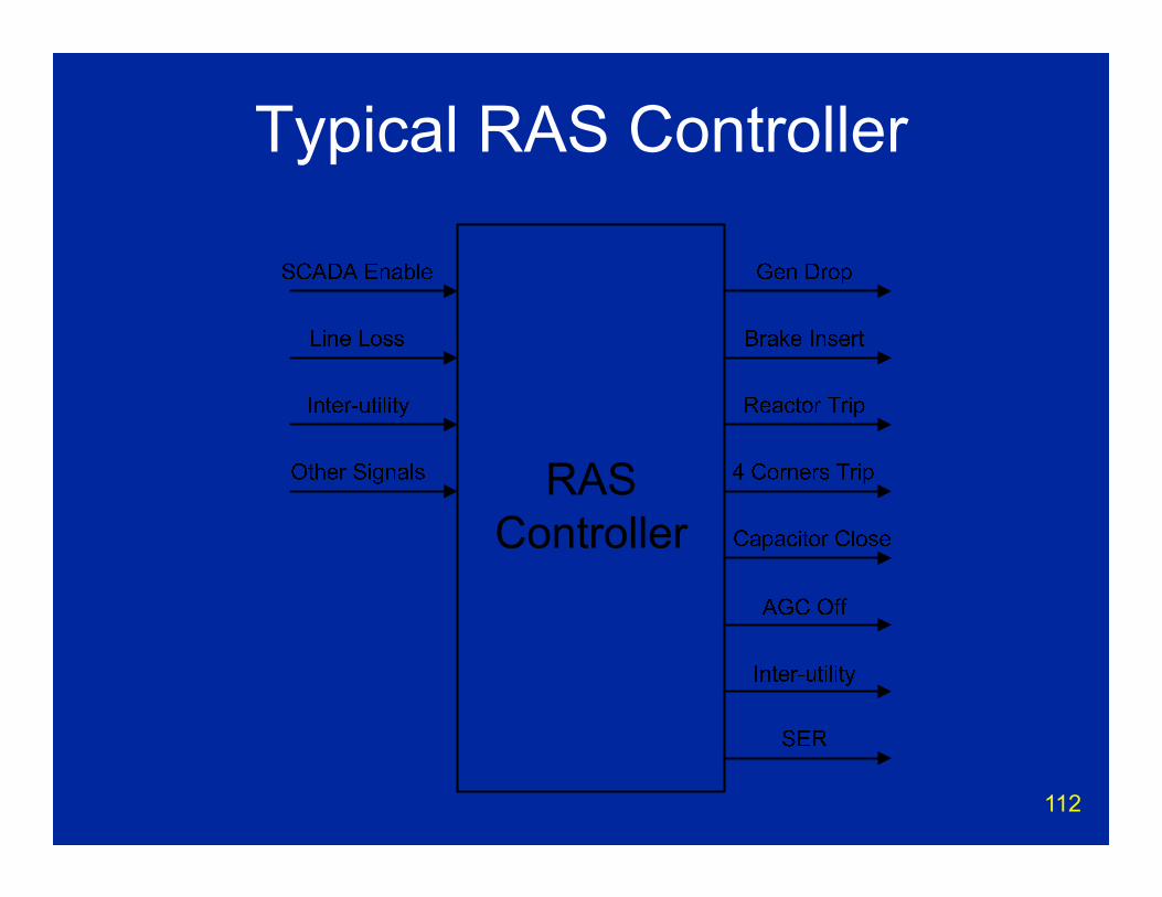
Typical RAS Controller
113
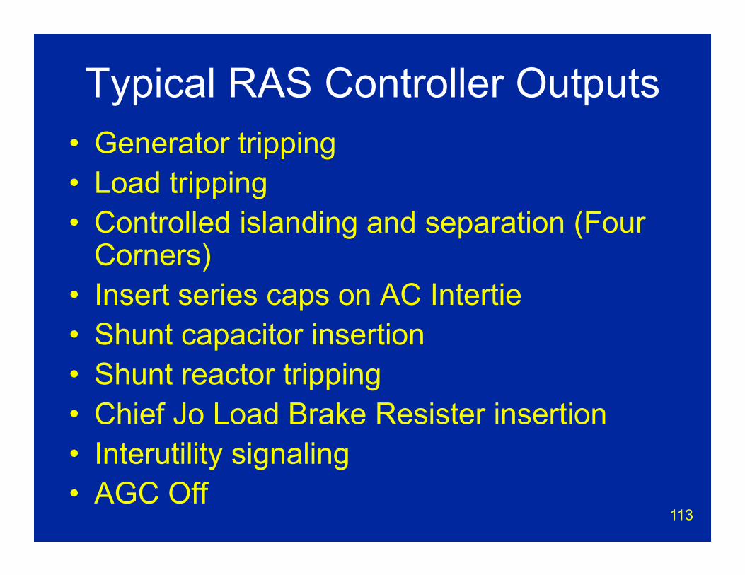
Typical RAS Controller Outputs• Generator tripping• Load tripping • Controlled islanding and separation (Four
Corners)• Insert series caps on AC Intertie• Shunt capacitor insertion• Shunt reactor tripping• Chief Jo Load Brake Resister insertion• Interutility signaling• AGC Off

114
Chief Jo Brake
1400 Megawatts @ 230 kV
115
RAS Enabling Criteria• Power transfer levels• Direction of power flow• System configuration• Some utilities are considering automatic
enabling/disabling based on SCADA data• Phasor measurement capability in relays
can be used to enable RAS actions
116
RAS Design Criteria• Generally fully redundant • Generally use alternate route on
telecommunications• Extensive use of transfer trip for signaling
between substations, power plants, control centers, and RAS controllers
117
UFOs vs. Power Outages

118
the end
Jon F. DaumeBonneville Power Administration
retired
March 15, 2011


Transmission System Faults and Event AnalysisFault Analysis Theory
andModern Fault Analysis Methods
Presented by:Matthew Rhodes
Electrical Engineer, SRP1
Transmission System Fault Theory
• Symmetrical Fault Analysis• Symmetrical Components• Unsymmetrical Fault Analysis using
sequence networks
• Lecture material originally developed by Dr. Richard Farmer, ASU Research Professor
2
3
Symmetrical Faults
4
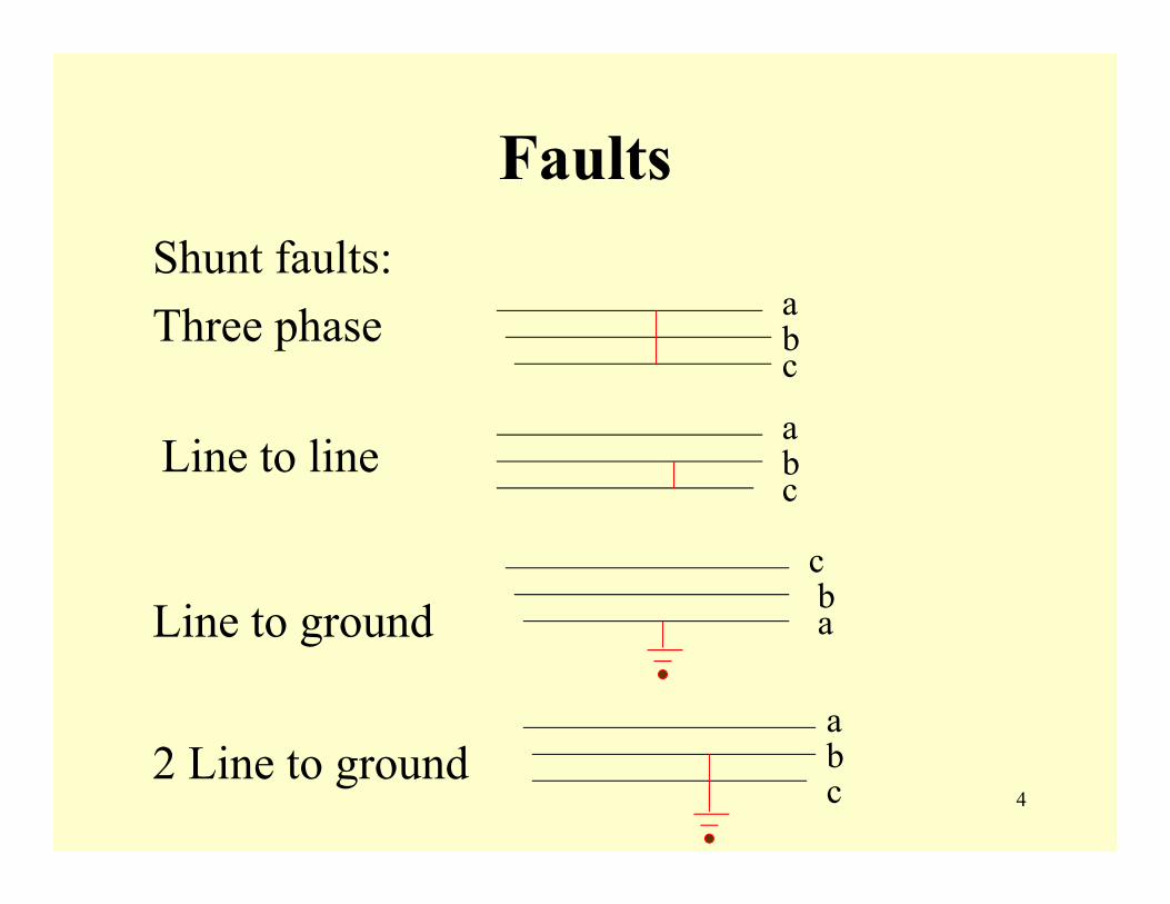
FaultsShunt faults:Three phase a
bc
Line to line
Line to ground
2 Line to ground
ba
c
abc
abc
5
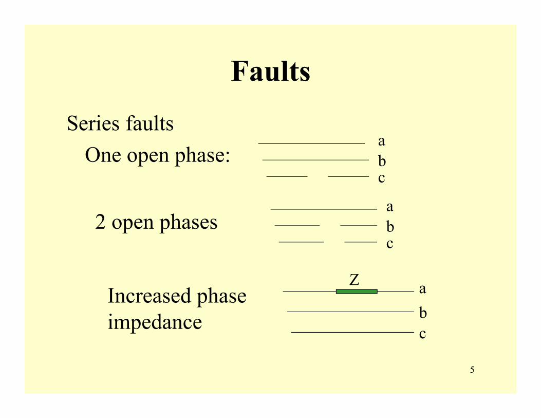
Faults
Series faultsOne open phase:
abc
2 open phasesabc
Increased phase impedance
Z abc
6
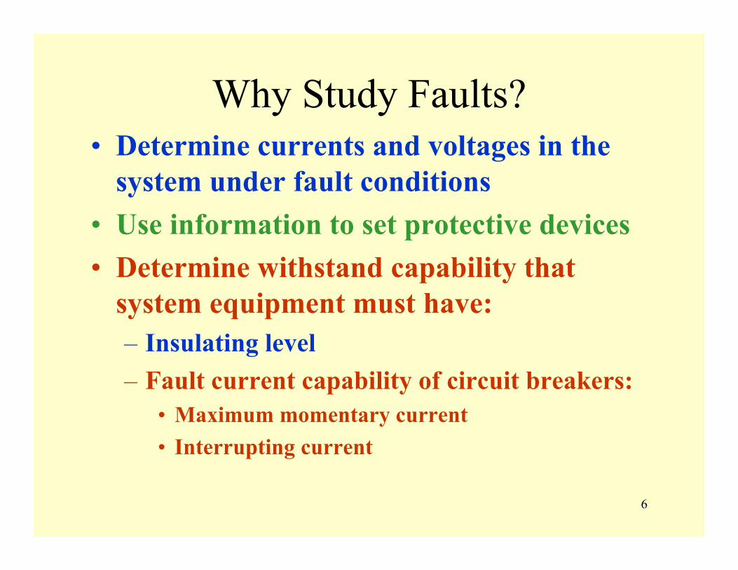
Why Study Faults?• Determine currents and voltages in the
system under fault conditions• Use information to set protective devices• Determine withstand capability that
system equipment must have:– Insulating level– Fault current capability of circuit breakers:
• Maximum momentary current• Interrupting current
7
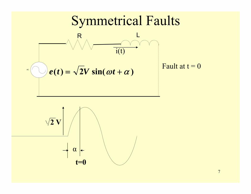
Symmetrical Faults
α
t=0
2 V
i(t)
Fault at t = 0AC
R L
)sin(2)( αω += tVte
8
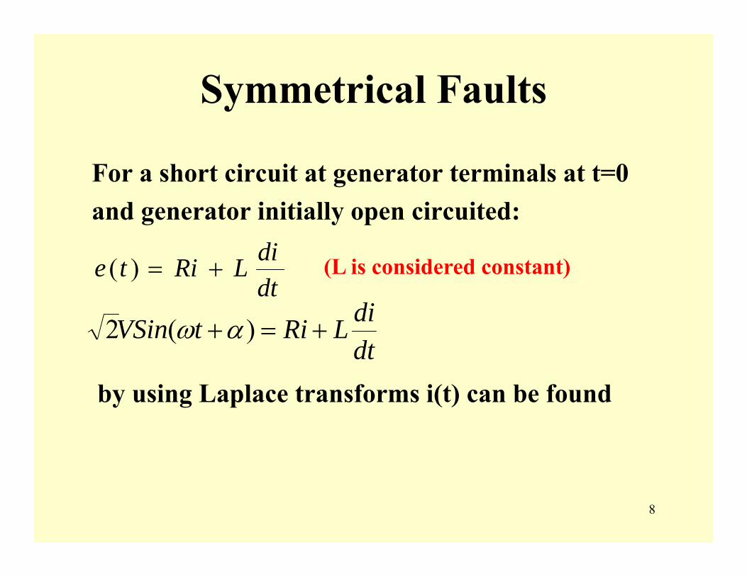
Symmetrical Faults
For a short circuit at generator terminals at t=0and generator initially open circuited:
dtdiLRite +=)(
dtdiLRitVSin +=+ )(2 αω
by using Laplace transforms i(t) can be found
(L is considered constant)
9
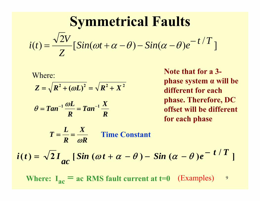
Symmetrical Faults]/)()([2)( TteSintSin
ZVti −−−−+= θαθαω
2222 )( XRLRZ +=+= ω
RXTan
RLTan 11 −− ==
ωθ
Where:
RX
RLT
ω== Time Constant
]/)()([2)( TteSintSinacIti −−−−+= θαθαω
Where: Iac = ac RMS fault current at t=0 (Examples)
Note that for a 3-phase system α will be different for each phase. Therefore, DC offset will be different for each phase
10
t = 0
acI2 iac
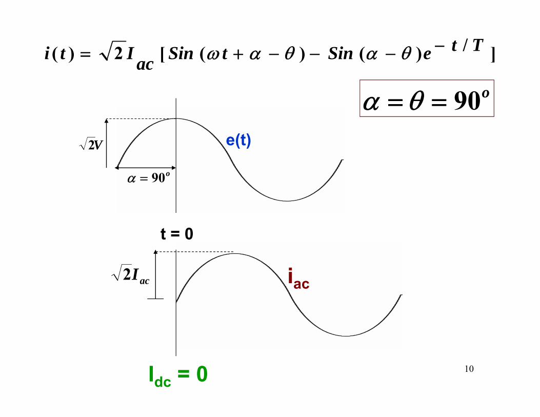
Idc = 0
]/)()([2)( TteSintSinacIti −−−−+= θαθαω
o90== θαV2 e(t)
o90=α
11
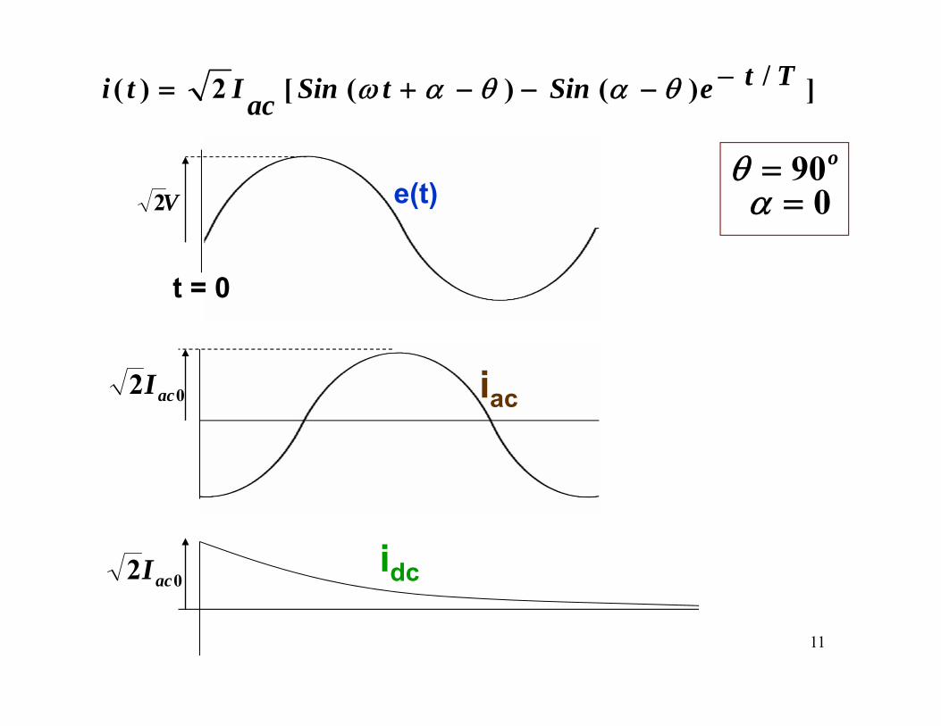
]/)()([2)( TteSintSinacIti −−−−+= θαθαω
0=αo90=θ
V2 e(t)
t = 0
iac02 acI
02 acI idc
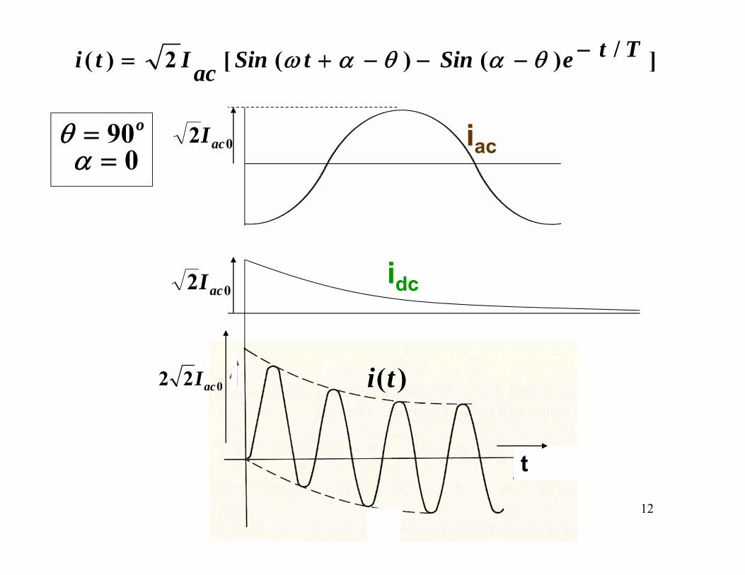
12
iac02 acI
02 acI idc
022 acI
t
0=αo90=θ
]/)()([2)( TteSintSinacIti −−−−+= θαθαω
)(ti
13
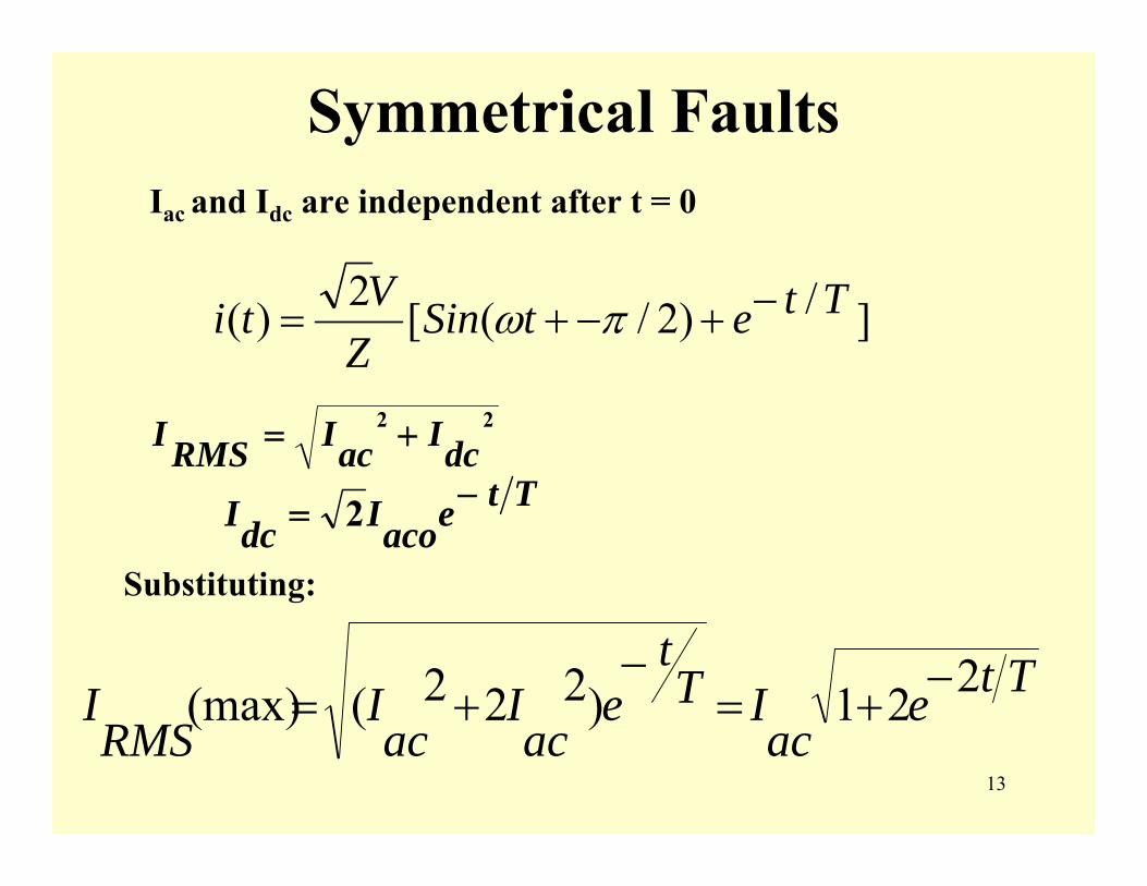
Symmetrical FaultsIac and Idc are independent after t = 0
22
dcIacIRMSI +=
TteacoIdcI −= 2
Substituting:
Tteac
ITt
eac
Iac
IRMS
I 221)222((max) −+=−
+=
]/)2/([2)( TtetSinZVti −+−+= πω
14
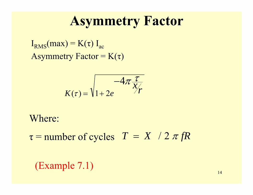
Asymmetry FactorIRMS(max) = K(τ) Iac
Asymmetry Factor = K(τ)
rxeK
τπτ
421)(−
+=
Where:
τ = number of cycles
(Example 7.1)
fRXT π2/=
15
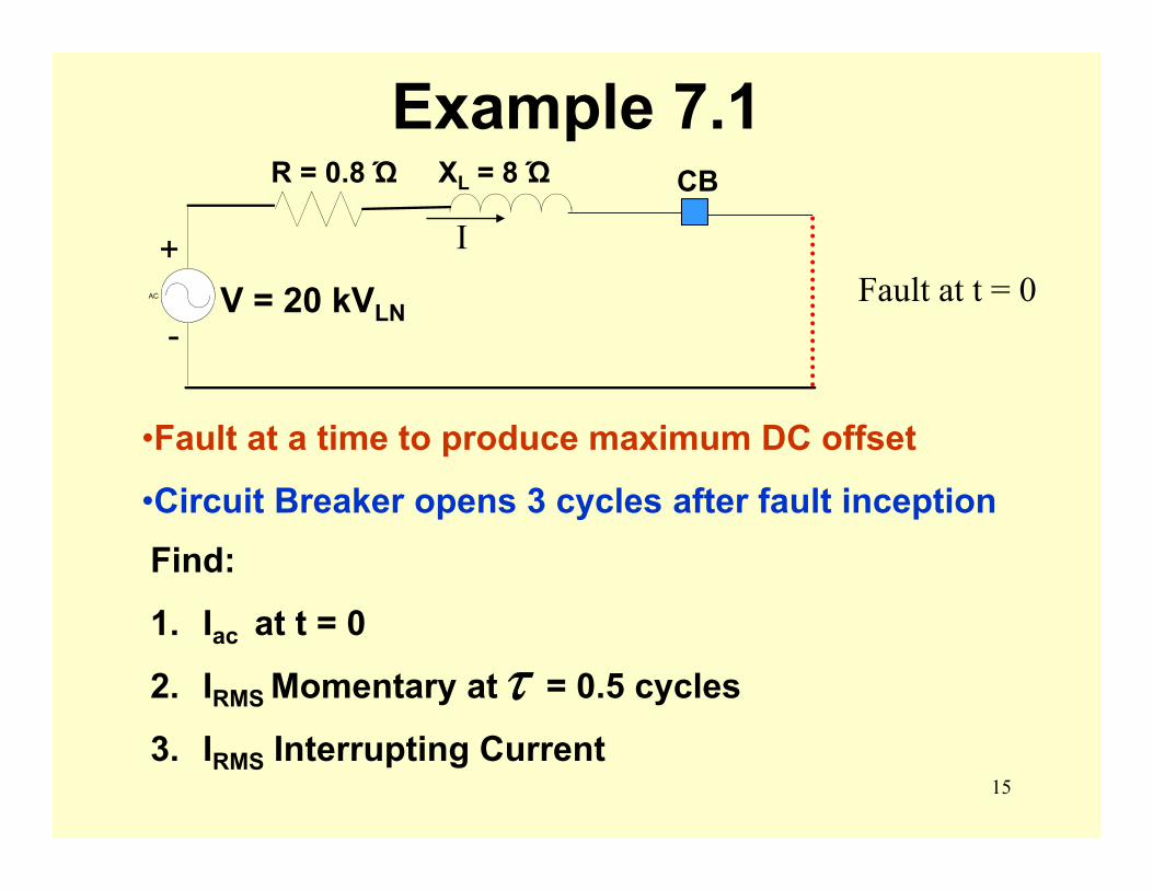
Example 7.1
•Fault at a time to produce maximum DC offset
•Circuit Breaker opens 3 cycles after fault inception
IFault at t = 0AC
R = 0.8 Ώ XL = 8 Ώ
V = 20 kVLN-
+
CB
Find:
1. Iac at t = 0
2. IRMS Momentary at = 0.5 cycles
3. IRMS Interrupting Current
τ

16
Example 7.1a. RMSAC kAI 488.2
88.020)0(
22=
+=
b.438.121)5.0( )10
5.(4=+=
Π−eKKAImomentary 577.3)488.2)(438.1( ==
c.
023.121)3( )103(4
=+=Π−eK
KAI ngInterrupti 545.2)488.2)(023.1( ==
17
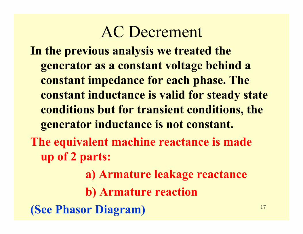
AC DecrementIn the previous analysis we treated the
generator as a constant voltage behind a constant impedance for each phase. The constant inductance is valid for steady state conditions but for transient conditions, the generator inductance is not constant.
The equivalent machine reactance is made up of 2 parts:
a) Armature leakage reactance b) Armature reaction
(See Phasor Diagram)
18
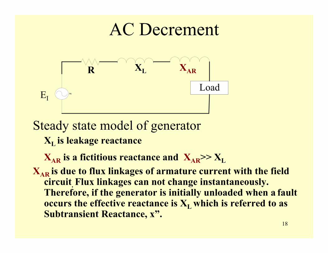
AC Decrement
Steady state model of generatorXL is leakage reactance
XAR is a fictitious reactance and XAR>> XL
XAR is due to flux linkages of armature current with the field circuit. Flux linkages can not change instantaneously. Therefore, if the generator is initially unloaded when a fault occurs the effective reactance is XL which is referred to as Subtransient Reactance, x”.
EI
R XL XAR
Load
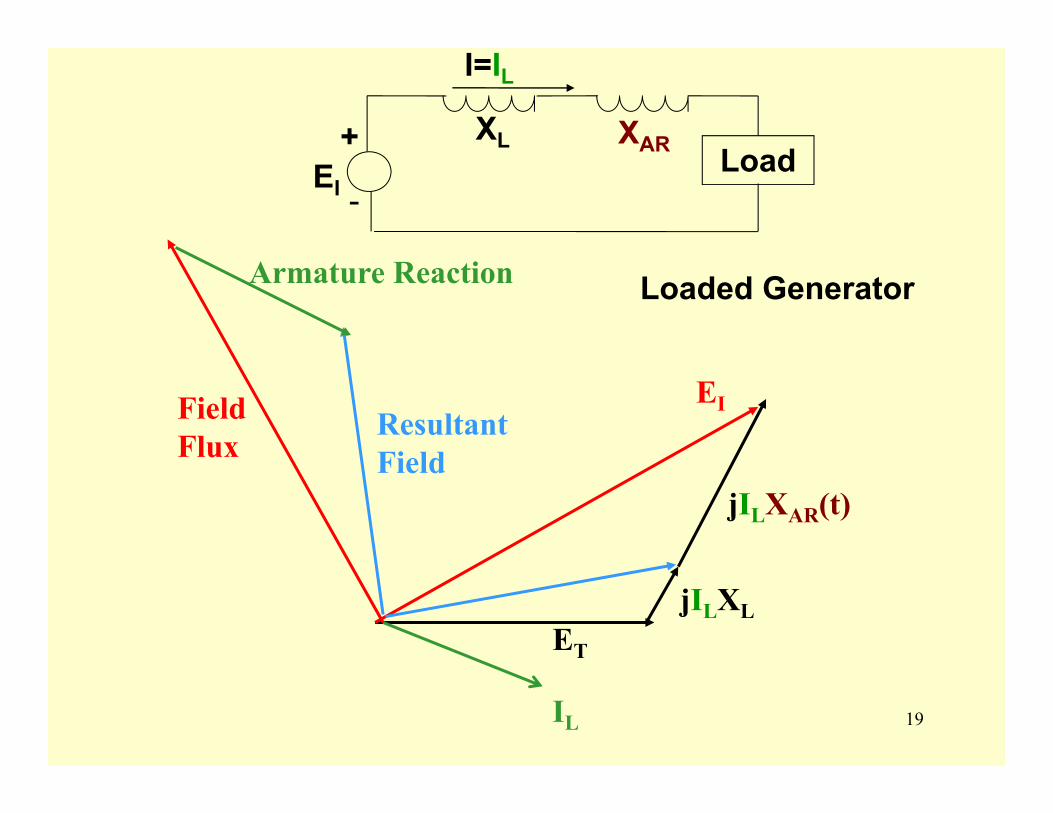
19IL
jILXL
jILXAR(t)
EIField Flux
Armature Reaction
Resultant Field
ET
XL XAR
-
+EI
I=IL
Load
Loaded Generator
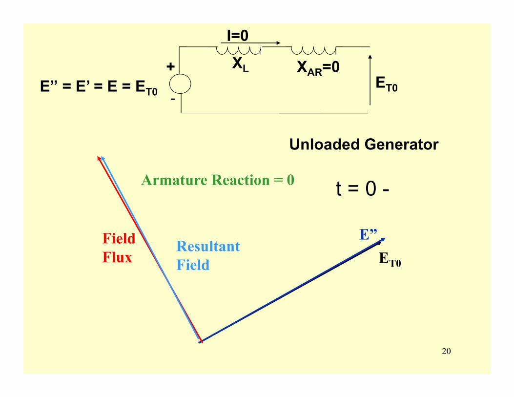
20
E”Field Flux
Armature Reaction = 0
Resultant Field ET0
t = 0 -
XL XAR=0ET0
-
+E” = E’ = E = ET0
I=0
Unloaded Generator
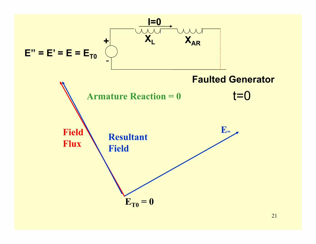
21
XL XAR
-
+E” = E’ = E = ET0
I=0
t=0
E”Field Flux
Armature Reaction = 0
Resultant Field
ET0 = 0
Faulted Generator
22
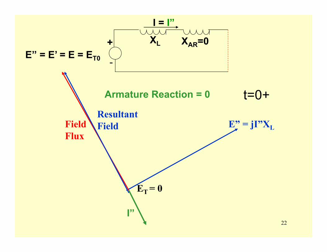
XL XAR=0
-
+E” = E’ = E = ET0
I = I”
E” = jI”XL
t=0+
Field Flux
Resultant Field
ET = 0
I”
Armature Reaction = 0
23
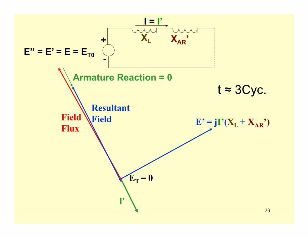
XL XAR’
-
+E” = E’ = E = ET0
I = I’
E’ = jI’(XL + XAR’)
t ≈ 3Cyc.
Field Flux
Resultant Field
ET = 0
I’
Armature Reaction = 0
24
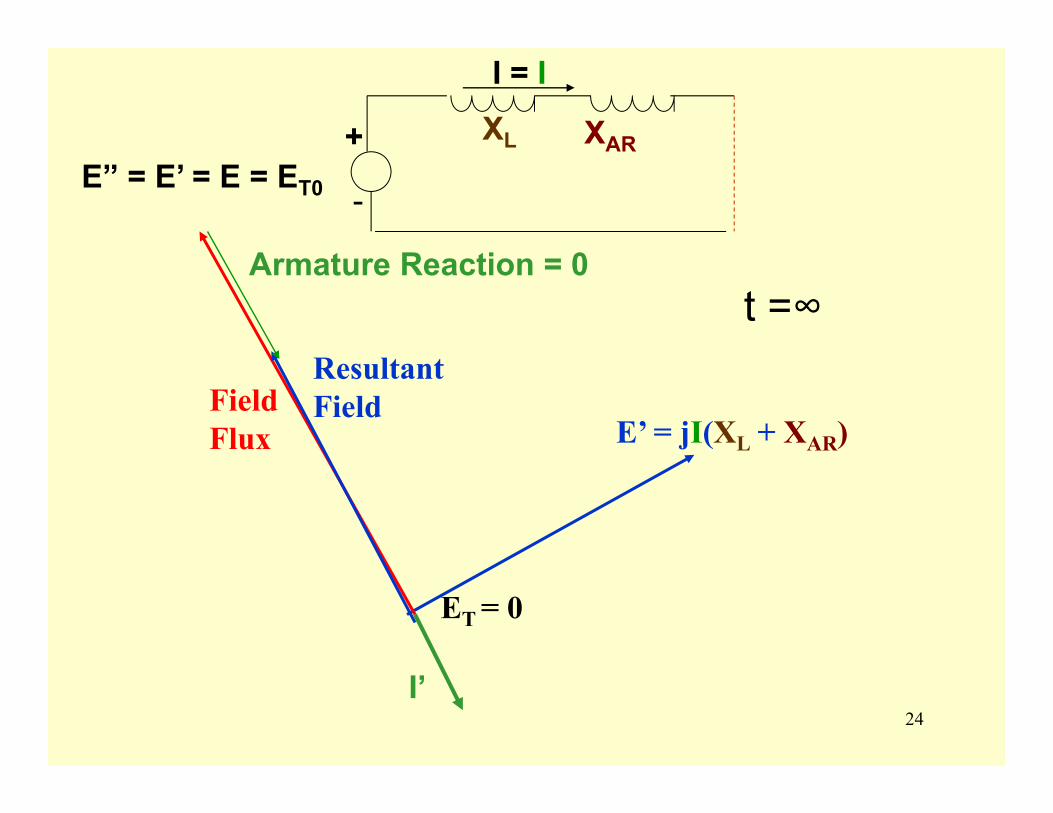
XL XAR
-
+E” = E’ = E = ET0
I = I
E’ = jI(XL + XAR)
t =∞
Field Flux
Resultant Field
ET = 0
I’
Armature Reaction = 0

25
AC DecrementAs fault current begins to flow, armature reaction will
increase with time thereby increasing the apparent reactance. Therefore, the ac component of the fault current will decrease with time to a steady state condition as shown in the figure below.
"2I '2I I2"2I
26
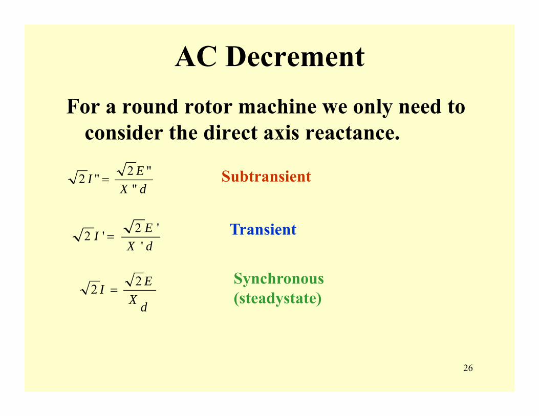
AC DecrementFor a round rotor machine we only need to
consider the direct axis reactance.
dXEI
""2"2 = Subtransient
dXEI
''2'2 =
dXEI 22 =
Transient
Synchronous(steadystate)
27
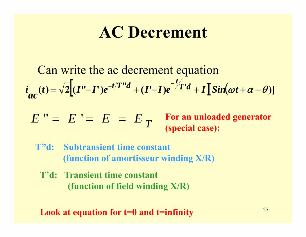
AC Decrement
Can write the ac decrement equation[ ] ([ )])'()'"(2)( '" θαω −++−+−=
−− tSinIeIIeIItaci dTtdTt
For an unloaded generator (special case):TEEEE === '"
T”d: Subtransient time constant (function of amortisseur winding X/R)
T’d: Transient time constant (function of field winding X/R)
Look at equation for t=0 and t=infinity
28
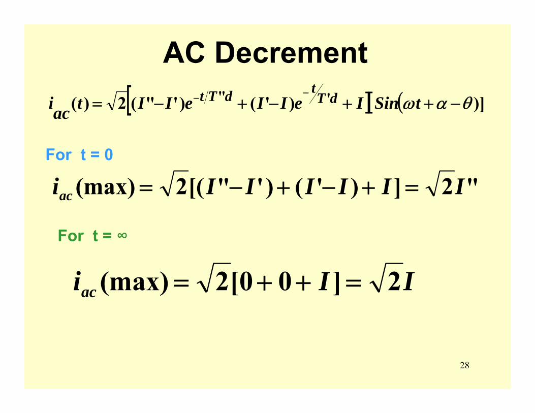
AC Decrement
For t = 0
[ ] ([ )])'()'"(2)( '" θαω −++−+−=−− tSinIeIIeIItaci dT
tdTt
For t = ∞
IIiac 2]00[2(max) =++=
"2])'()'"[(2(max) IIIIIIiac =+−+−=
29
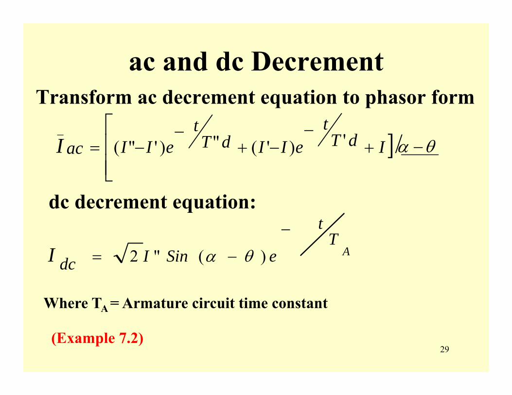
ac and dc DecrementTransform ac decrement equation to phasor form
] θα −+−
−+−
−=⎢⎢⎣
⎡/')'(")'"(
_IdT
teIIdT
teIIacI
dc decrement equation:
AT
t
eSinIdcI−
−= )("2 θα
Where TA = Armature circuit time constant
(Example 7.2)
30
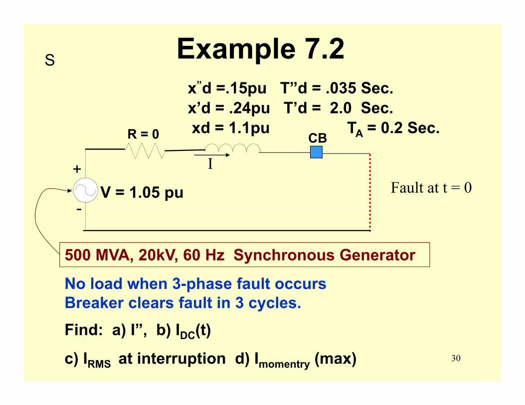
Example 7.2
IFault at t = 0AC
R = 0
V = 1.05 pu-
+
CB
x”d =.15pu T”d = .035 Sec.x’d = .24pu T’d = 2.0 Sec.xd = 1.1pu TA = 0.2 Sec.
No load when 3-phase fault occurs Breaker clears fault in 3 cycles.Find: a) I”, b) IDC(t)
c) IRMS at interruption d) Imomentry (max)
S
500 MVA, 20kV, 60 Hz Synchronous Generator

31
Example 7.2⎥⎦⎤
⎢⎣⎡ +⎟
⎠⎞
⎜⎝⎛ −+⎟
⎠⎞
⎜⎝⎛ −= −−
1.11
1.11
24.1
24.1
15.105.1)( 2035. tt
AC eetI
2.max "2)(
t
DC eItI −= KAIBase 434.14
320500
==
kApudx
EI 1010.715.05.1
""" ==== a
DCI
2.2.max 9.9)7(2)(
tt
DC eetI −−== b
32
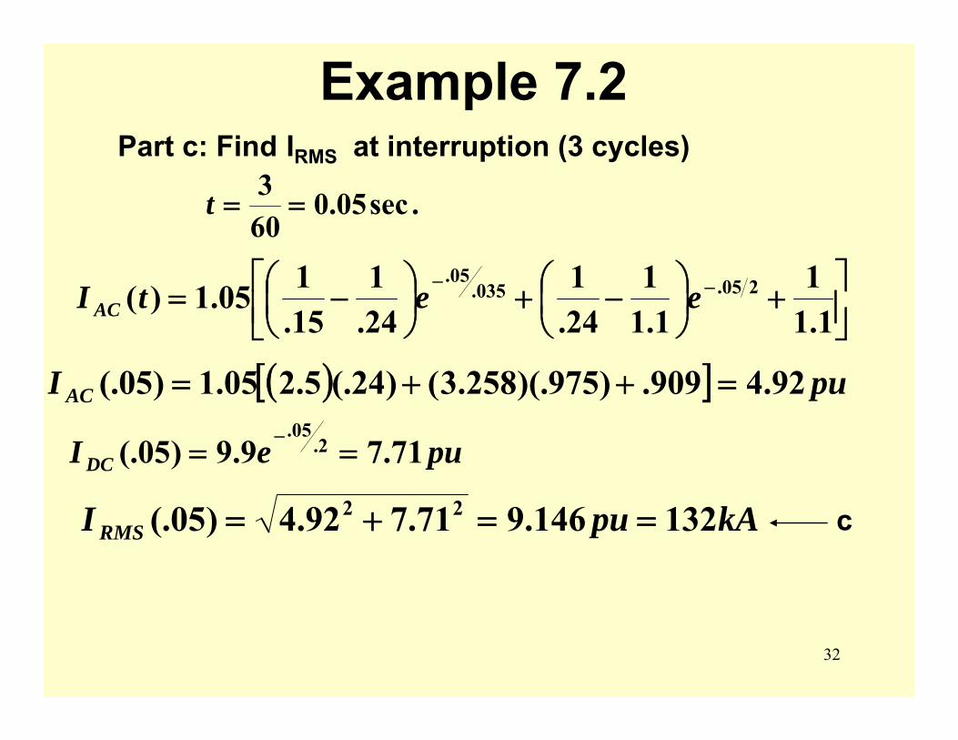
Example 7.2Part c: Find IRMS at interruption (3 cycles)
.sec05.0603==t
⎥⎦⎤
⎢⎣⎡ +⎟
⎠⎞
⎜⎝⎛ −+⎟
⎠⎞
⎜⎝⎛ −= −−
1.11
1.11
24.1
24.1
15.105.1)( 205.035.
05.eetI AC
( )[ ] puI AC 92.4909.)975)(.258.3()24(.5.205.1)05(. =++=
pueI DC 71.79.9)05(. 2.05.
==−
kApuI RMS 132146.971.792.4)05(. 22 ==+= c
33
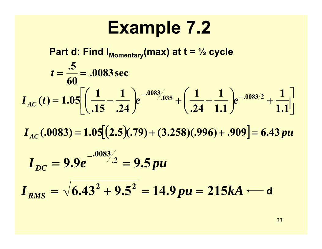
Example 7.2Part d: Find IMomentary(max) at t = ½ cycle
sec0083.605.==t
( )[ ] puI AC 43.6909.)996)(.258.3()79(.5.205.1)0083(. =++=
⎥⎦⎤
⎢⎣⎡ +⎟
⎠⎞
⎜⎝⎛ −+⎟
⎠⎞
⎜⎝⎛ −= −−
1.11
1.11
24.1
24.1
15.105.1)( 20083.035.
0083.eetI AC
pueI DC 5.99.9 2.0083.
==−
kApuI RMS 2159.145.943.6 22 ==+= d
34
TurbineGen.
Energy

35
Superposition for Fault Analysis
36
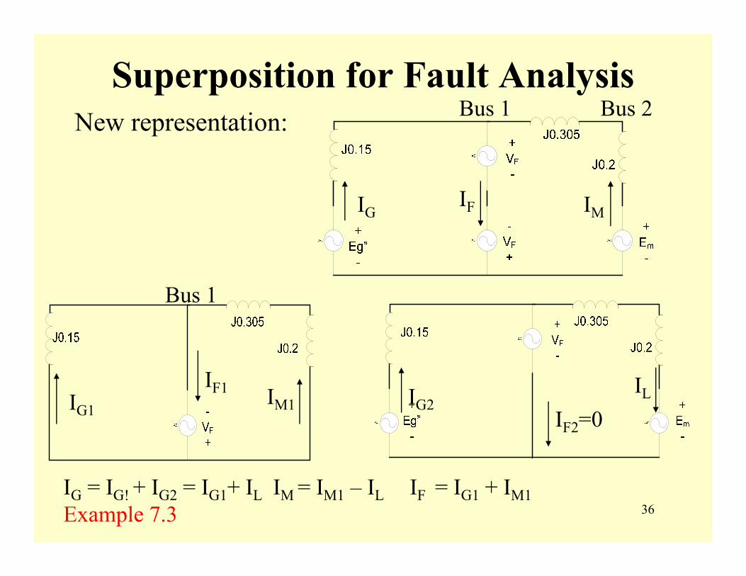
Superposition for Fault AnalysisNew representation:
IF1
IF2=0
Bus 1
Bus 1 Bus 2
IG = IG! + IG2 = IG1+ IL IM = IM1 – IL IF = IG1 + IM1Example 7.3
IG1IG2
ILIM1
IGIF IM
37
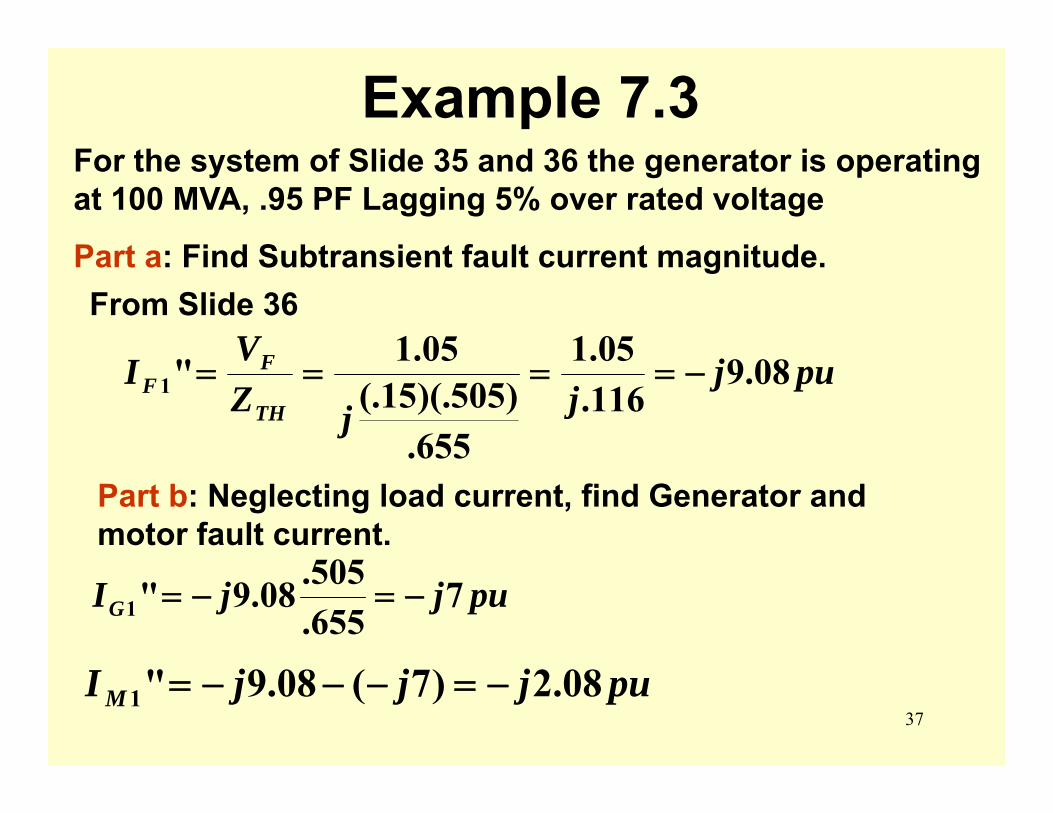
Example 7.3For the system of Slide 35 and 36 the generator is operating at 100 MVA, .95 PF Lagging 5% over rated voltage
Part a: Find Subtransient fault current magnitude.From Slide 36
pujjjZ
VITH
FF 08.9
116.05.1
655.)505)(.15(.
05.1"1 −====
Part b: Neglecting load current, find Generator and motor fault current.
pujjIG 7655.505.08.9"1 −=−=
pujjjI M 08.2)7(08.9"1 −=−−−=
38
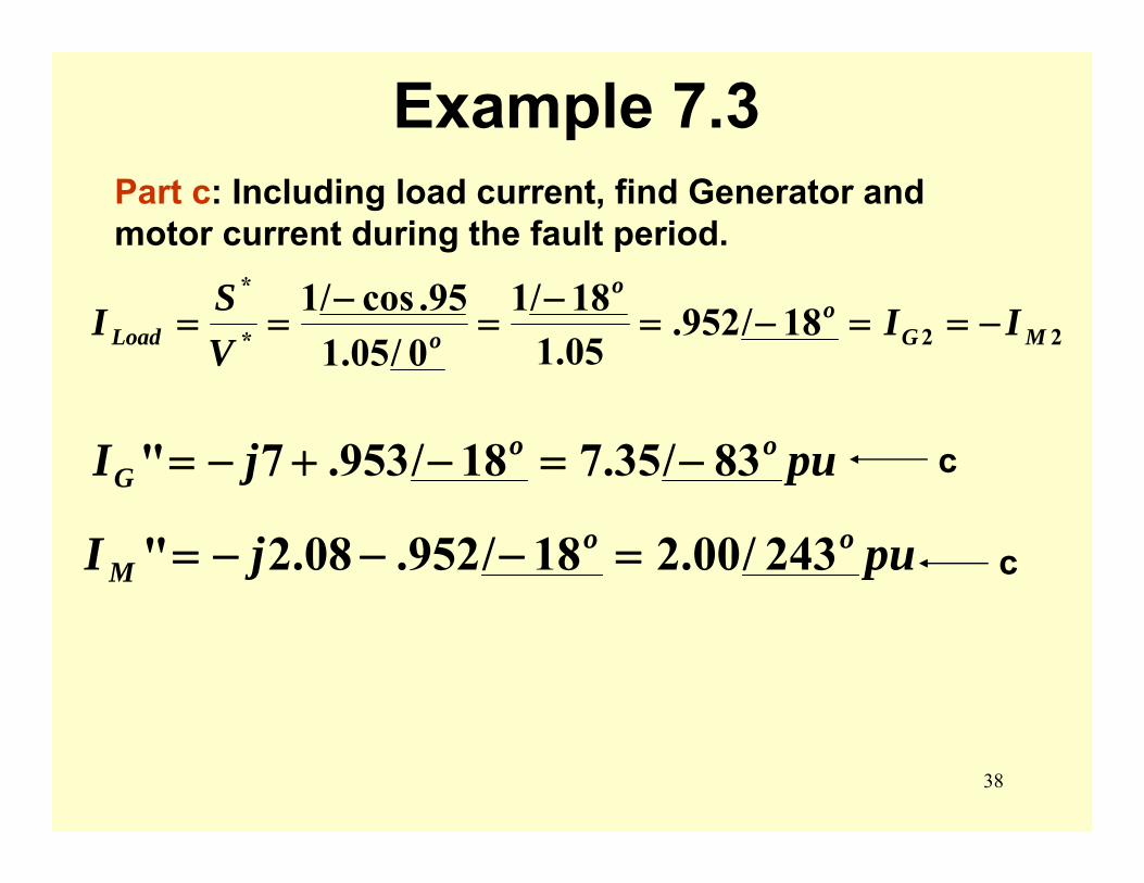
Example 7.3Part c: Including load current, find Generator and motor current during the fault period.
22*
*
18/952.05.118/1
0/05.195.cos/1
MGo
o
oLoad IIVSI −==−=
−=
−==
pujI ooG 83/35.718/953.7" −=−+−=
pujI ooM 243/00.218/952.08.2" =−−−=
c
c

39
Z Bus Method
For Z bus method of fault studies the following approximations are made:
• Neglect load current• Model series impedance only• Model generators and synchronous
motors by voltage behind a reactance for the positive sequence system
40
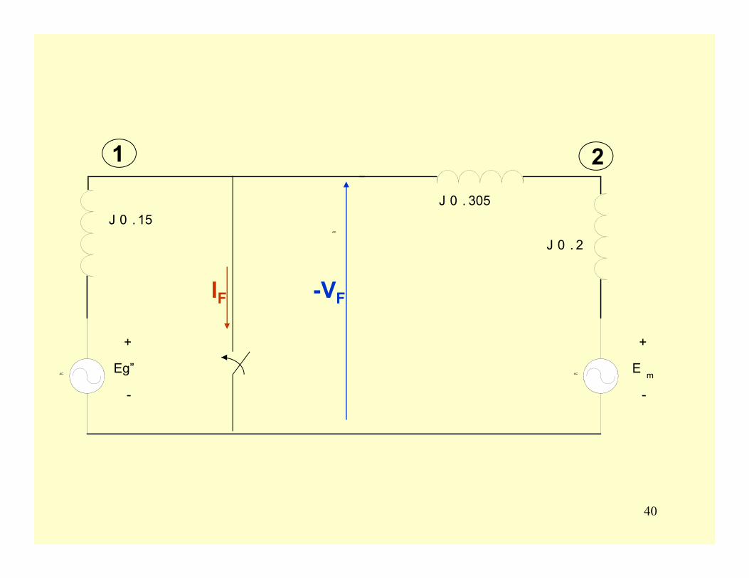
AC
AC
AC
+
Eg”
-
+
E m
-
J 0 . 2
J 0 . 305J 0 . 15
1 2
-VFIF
41
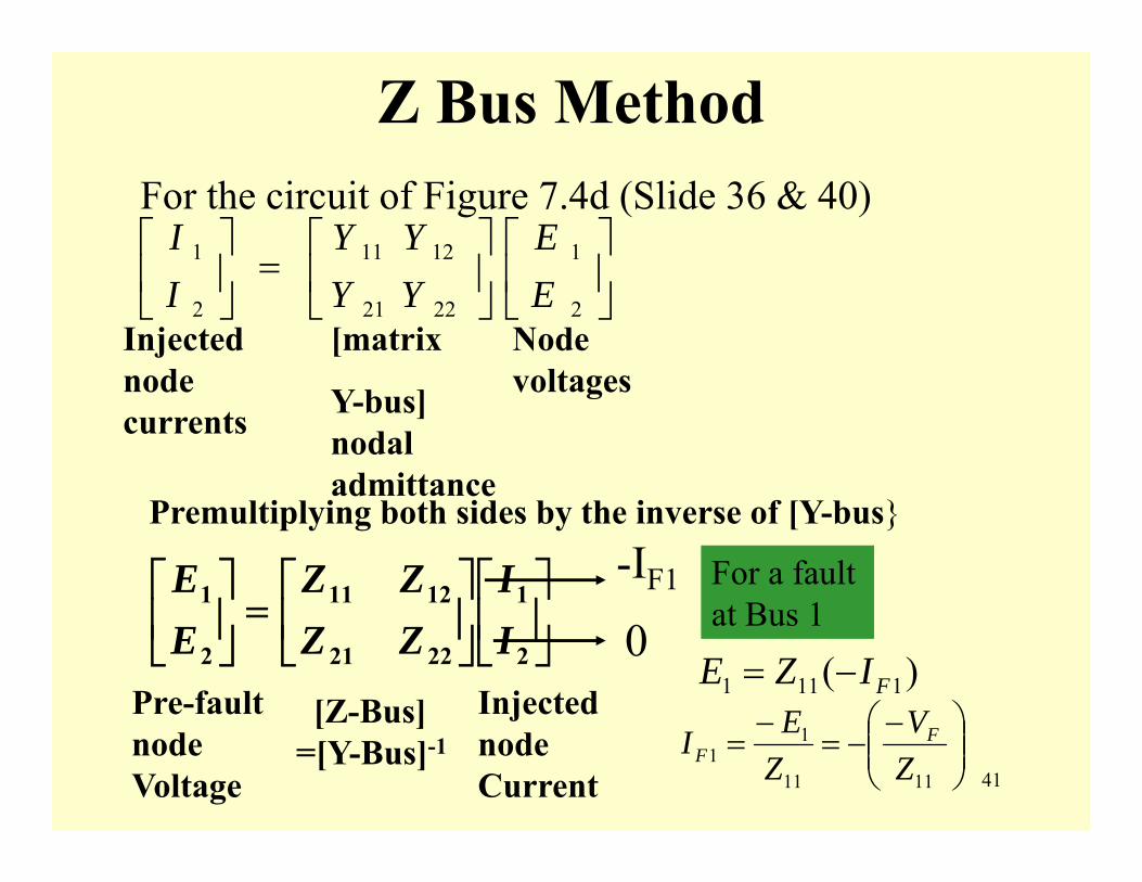
Z Bus MethodFor the circuit of Figure 7.4d (Slide 36 & 40)
⎥⎦
⎤⎢⎣
⎡⎥⎦
⎤⎢⎣
⎡=⎥
⎦
⎤⎢⎣
⎡
2
1
22
12
21
11
2
1
EE
YY
YY
II
Injected node currents
[matrix
Y-bus] nodal admittance
Node voltages
Premultiplying both sides by the inverse of [Y-bus
Pre-fault node Voltage
[Z-Bus] =[Y-Bus]-1
Injected node Current
-IF1
0For a fault at Bus 1
)( 1111 FIZE −=
⎟⎟⎠
⎞⎜⎜⎝
⎛ −−=
−=
1111
11 Z
VZEI F
F
⎥⎦
⎤⎢⎣
⎡⎥⎦
⎤⎢⎣
⎡=⎥
⎦
⎤⎢⎣
⎡
2
1
2221
1211
2
1
II
ZZZZ
EE
42
Z-Bus Method
⎟⎟⎠
⎞⎜⎜⎝
⎛ −−=
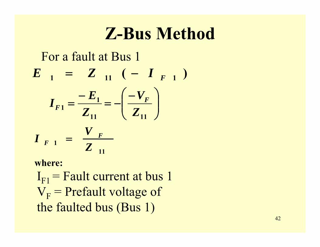
−=
1111
11 Z
VZEI F
F
)( 1111 FIZE −=
111 Z
VI FF =
where:
For a fault at Bus 1
IF1 = Fault current at bus 1 VF = Prefault voltage of the faulted bus (Bus 1)

43
Z-Bus MethodFor N bus system, fault on Bus n
⎥⎥⎥⎥⎥⎥⎥⎥
⎦
⎤
⎢⎢⎢⎢⎢⎢⎢⎢
⎣
⎡
−
⎥⎥⎥⎥⎥⎥⎥⎥
⎦
⎤
⎢⎢⎢⎢⎢⎢⎢⎢
⎣
⎡
=
⎥⎥⎥⎥⎥⎥⎥⎥
⎦
⎤
⎢⎢⎢⎢⎢⎢⎢⎢
⎣
⎡
0.
000
...,...
.
.
.
.
.
321
321
33333231
22232221
11131211
3
2
1
Fn
NNNnNNN
nNnnnnn
Nn
Nn
Nn
N
N I
ZZZZZ
ZZZZZZZZZZZZZZZZZZZZ
E
EEEE
-VF
nn
FFn Z
VI = Where: VF = Pre-fault voltage at faulted bus Znn = Thevinen impedance

44
Z-Bus MethodAfter IFn is found the voltage at any bus can be
found from:E1 = Z1n (-Ifn) E2 = Z2n(-Ifn) Etc.
If voltage at each bus is found, current through any branch can be found:I12 = (E1 - E2) / Ž12 Etc/Note: Ž12 is series impedance between Bus1
and Bus 2, not from Z-Bus.(Example 7.4)
45
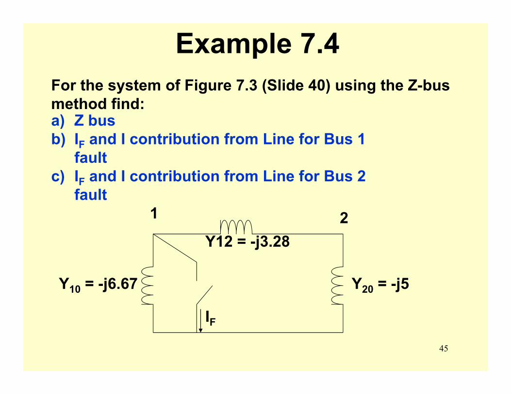
Example 7.4For the system of Figure 7.3 (Slide 40) using the Z-bus method find:a) Z busb) IF and I contribution from Line for Bus 1
faultc) IF and I contribution from Line for Bus 2
fault
Y20 = -j5Y10 = -j6.67
Y12 = -j3.28
1 2
IF
46
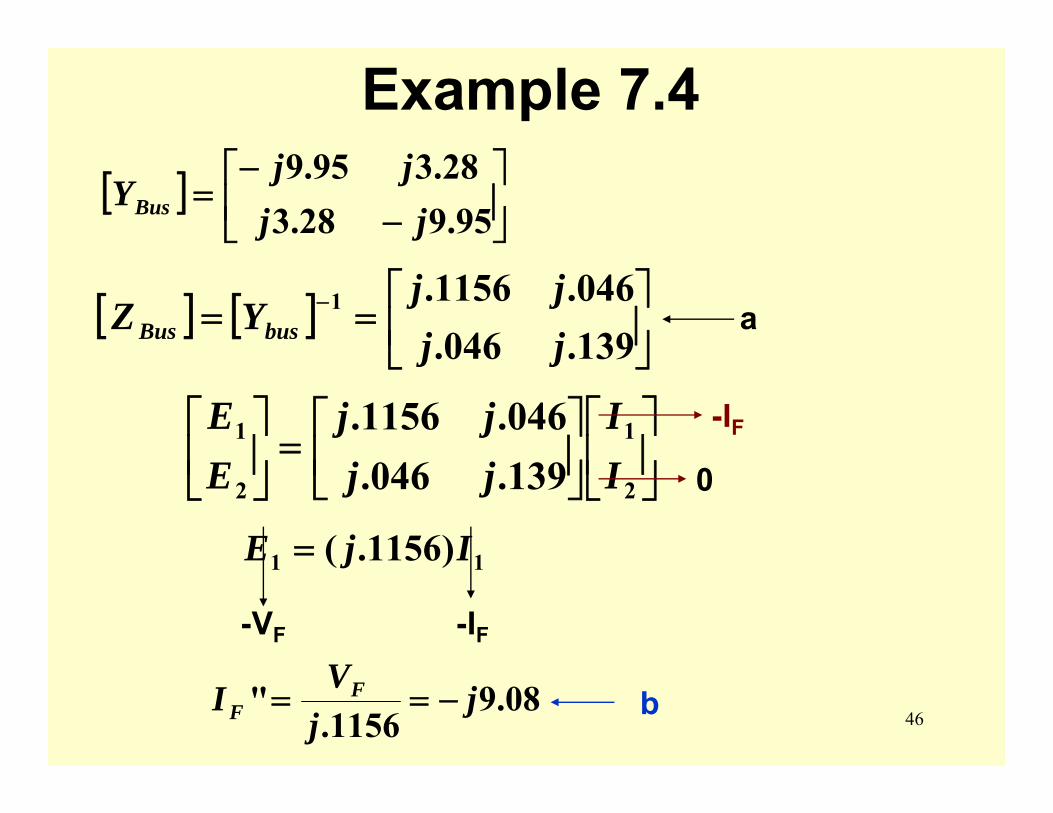
Example 7.4[ ] ⎥
⎦
⎤⎢⎣
⎡−
−=
95.928.328.395.9
jjjj
YBus
[ ] [ ] ⎥⎦
⎤⎢⎣
⎡== −
139.046.046.1156.1
jjjj
YZ busBus
⎥⎦
⎤⎢⎣
⎡⎥⎦
⎤⎢⎣
⎡=⎥
⎦
⎤⎢⎣
⎡
2
1
2
1
139.046.046.1156.
II
jjjj
EE
0
-IF
11 )1156.( IjE =
-VF -IF
08.91156.
" jjVI F
F −==
a
b
47
Example 7.4
⎥⎦
⎤⎢⎣
⎡⎥⎦
⎤⎢⎣
⎡=⎥
⎦
⎤⎢⎣
⎡
2
1
2
1
139.046.046.1156.
II
jjjj
EE
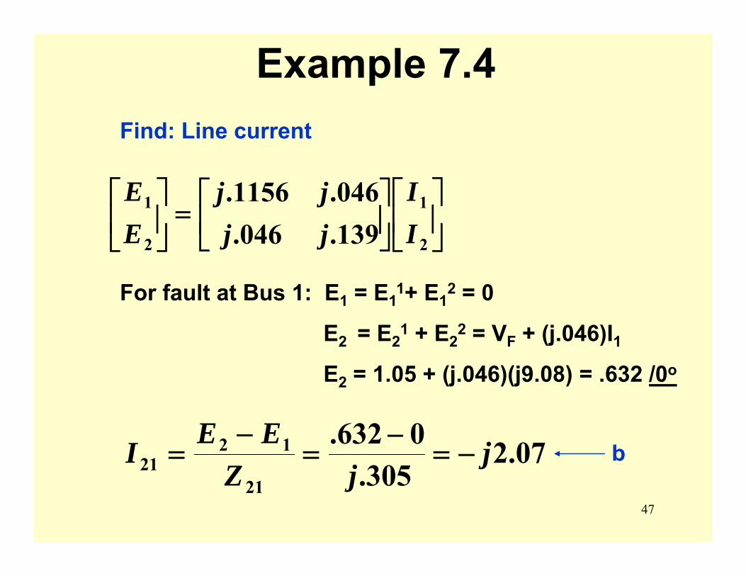
For fault at Bus 1: E1 = E11+ E1
2 = 0
E2 = E21 + E2
2 = VF + (j.046)I1E2 = 1.05 + (j.046)(j9.08) = .632 /0o
07.2305.
0632.21
1221 j
jZEEI −=
−=
−=
Find: Line current
b
48
Example 7.4
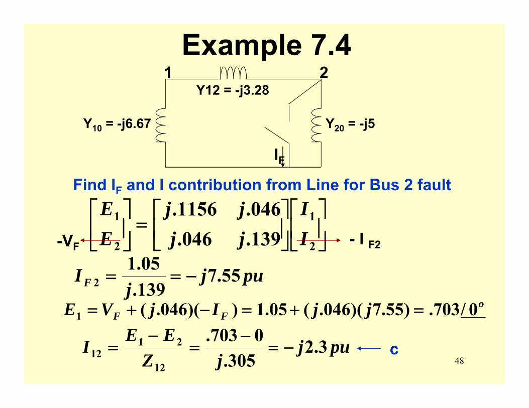
Y20 = -j5Y10 = -j6.67
Y12 = -j3.281 2
IFFind IF and I contribution from Line for Bus 2 fault
⎥⎦
⎤⎢⎣
⎡⎥⎦
⎤⎢⎣
⎡=⎥
⎦
⎤⎢⎣
⎡
2
1
2
1
139.046.046.1156.
II
jjjj
EE
-VF
pujj
IF 55.7139.05.1
2 −==
- I F2
oFF jjIjVE 0/703.)55.7)(046.(05.1))(046.(1 =+=−+=
pujjZ
EEI 3.2305.
0703.12
2112 −=
−=
−= c
49
Z-Bus Method
[Z-Bus] = [Y-Bus]-1
Will not cover formation of [Z-Bus] or [Y-Bus]
[Z-Bus] can be considered a fictitious circuit which has the appearance of a rake. See Figure 7.6 on Page 371.
50
nn
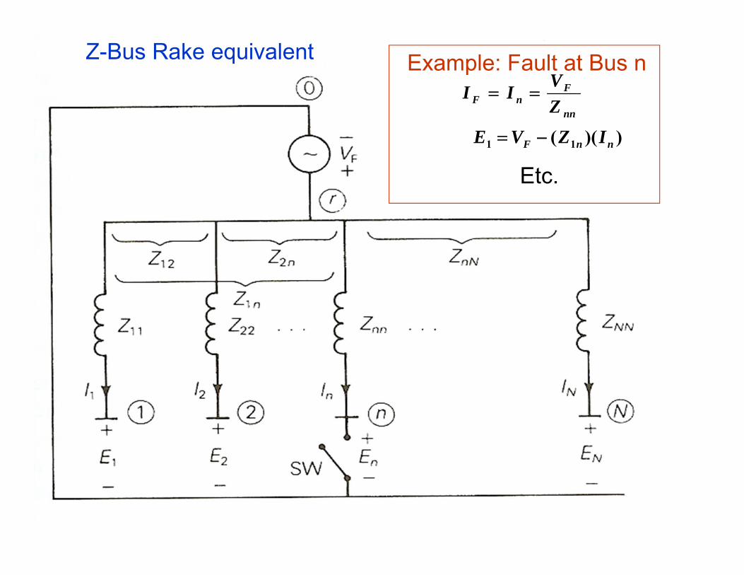
FnF Z
VII ==Example: Fault at Bus n
))(( 11 nnF IZVE −=
Etc.
Z-Bus Rake equivalent
51
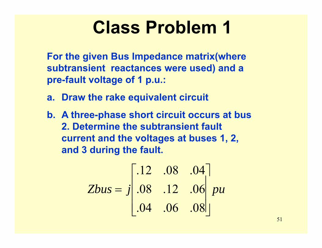
Class Problem 1
pujZbus⎥⎥⎥
⎦
⎤
⎢⎢⎢
⎣
⎡=
08.06.04.06.12.08.04.08.12.
For the given Bus Impedance matrix(where subtransient reactances were used) and a pre-fault voltage of 1 p.u.:
a. Draw the rake equivalent circuit
b. A three-phase short circuit occurs at bus 2. Determine the subtransient fault current and the voltages at buses 1, 2, and 3 during the fault.
52
Symmetrical Components
53
Symmetrical Components
Symmetrical Components is often referred to as the language of the Relay Engineer but it is important for all engineers that are involved in power.
The terminology is used extensively in the power engineering field and it is important to understand the basic concepts and terminology.

54
Symmetrical Components• Used to be more important as a calculating
technique before the advanced computer age. • Is still useful and important to make sanity
checks and back-of-an-envelope calculation.• We will be studying 3-phase systems in
general. Previously you have only considered balanced voltage sources, balanced impedance and balanced currents.
55
Symmetrical Components
naa
b b
c
Va Vb
Vc
Va
Vb
Vc
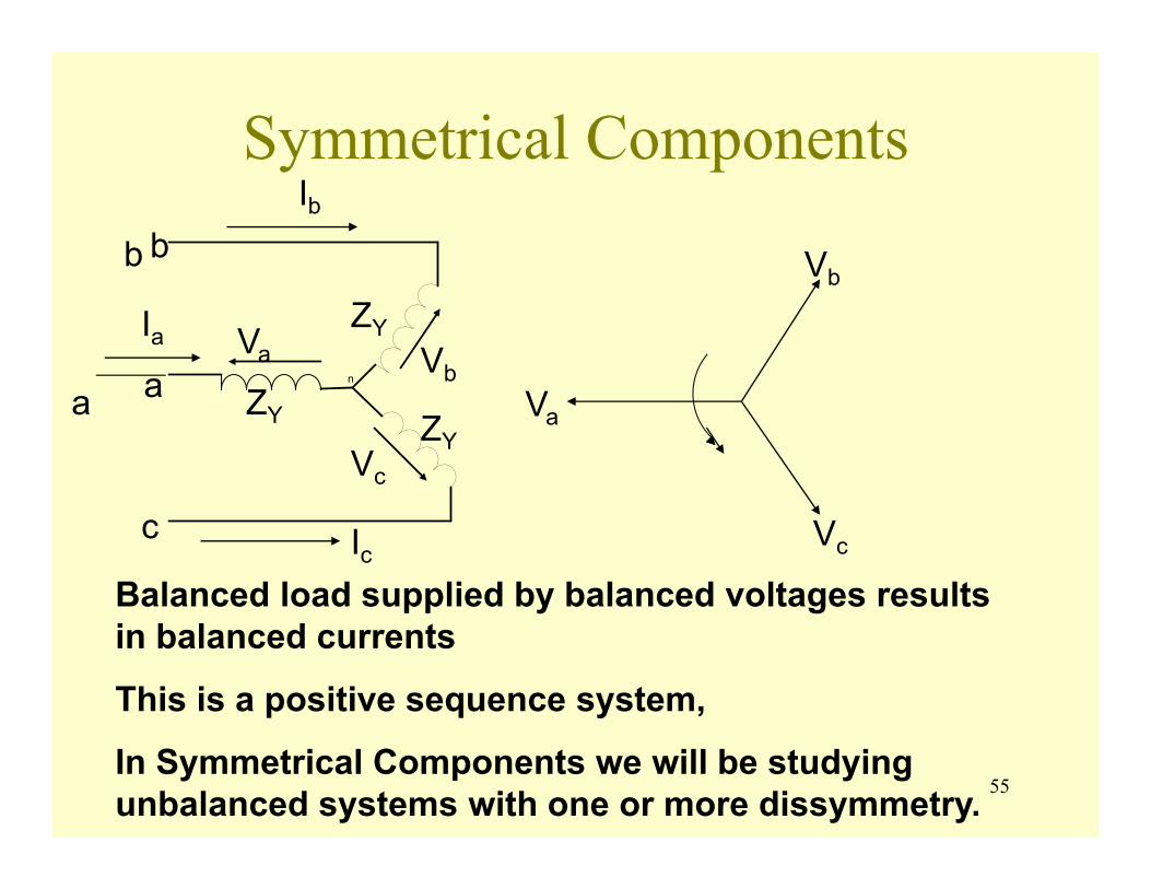
Balanced load supplied by balanced voltages results in balanced currents
This is a positive sequence system,
In Symmetrical Components we will be studying unbalanced systems with one or more dissymmetry.
ZY
ZYZY
Ib
Ia
Ic
56
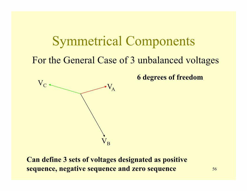
Symmetrical ComponentsFor the General Case of 3 unbalanced voltages
VA
VB
VC6 degrees of freedom
Can define 3 sets of voltages designated as positive sequence, negative sequence and zero sequence
57
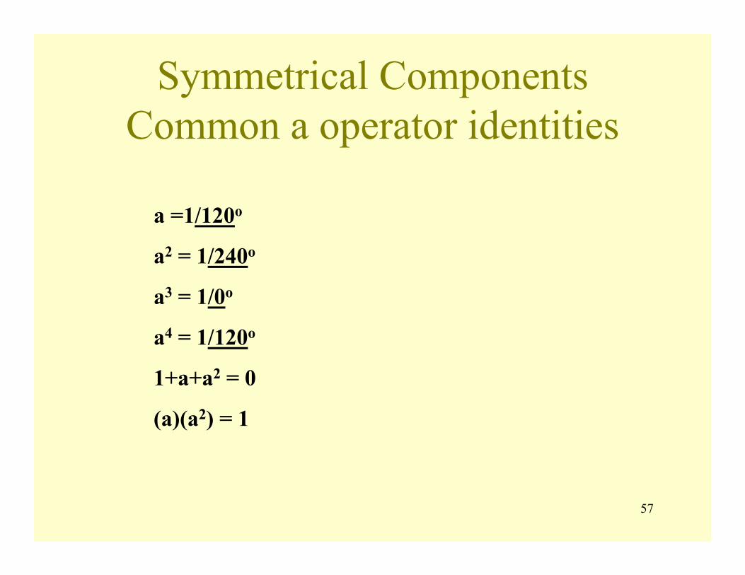
Symmetrical ComponentsCommon a operator identities
a =1/120o
a2 = 1/240o
a3 = 1/0o
a4 = 1/120o
1+a+a2 = 0
(a)(a2) = 1
58
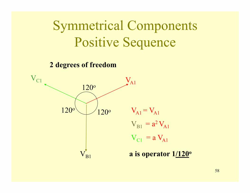
Symmetrical ComponentsPositive Sequence
120o
120o120o
VA1
VB1
VC1
2 degrees of freedom
VA1 = VA1
VB1 = a2 VA1
VC1 = a VA1
a is operator 1/120o
59
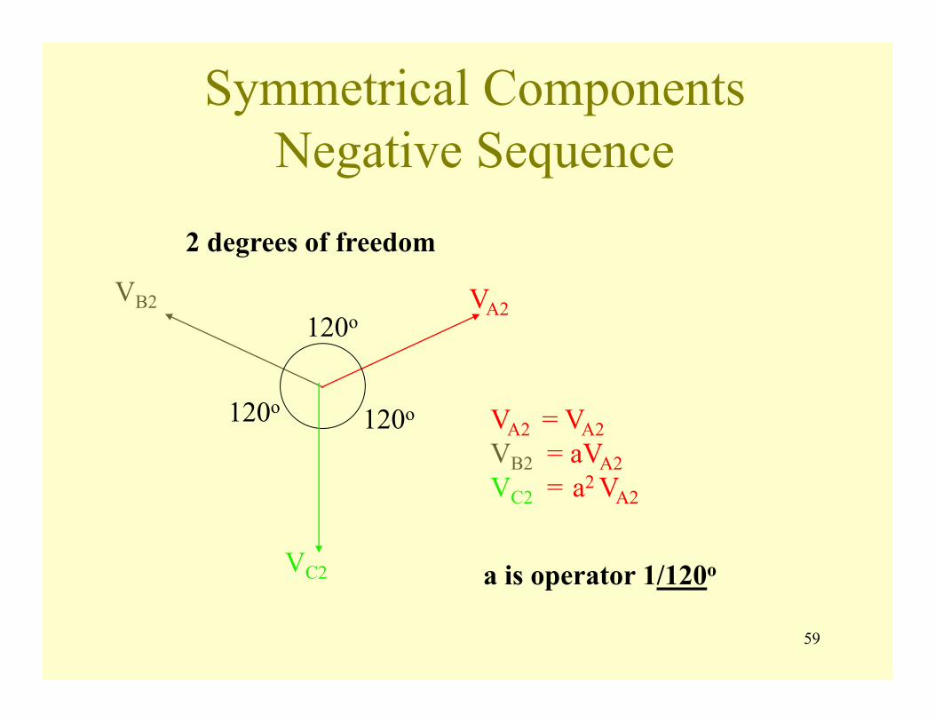
Symmetrical ComponentsNegative Sequence
120o
120o120o
VA2
VC2
VB2
2 degrees of freedom
a is operator 1/120o
VA2 = VA2 VB2 = aVA2 VC2 = a2 VA2
60
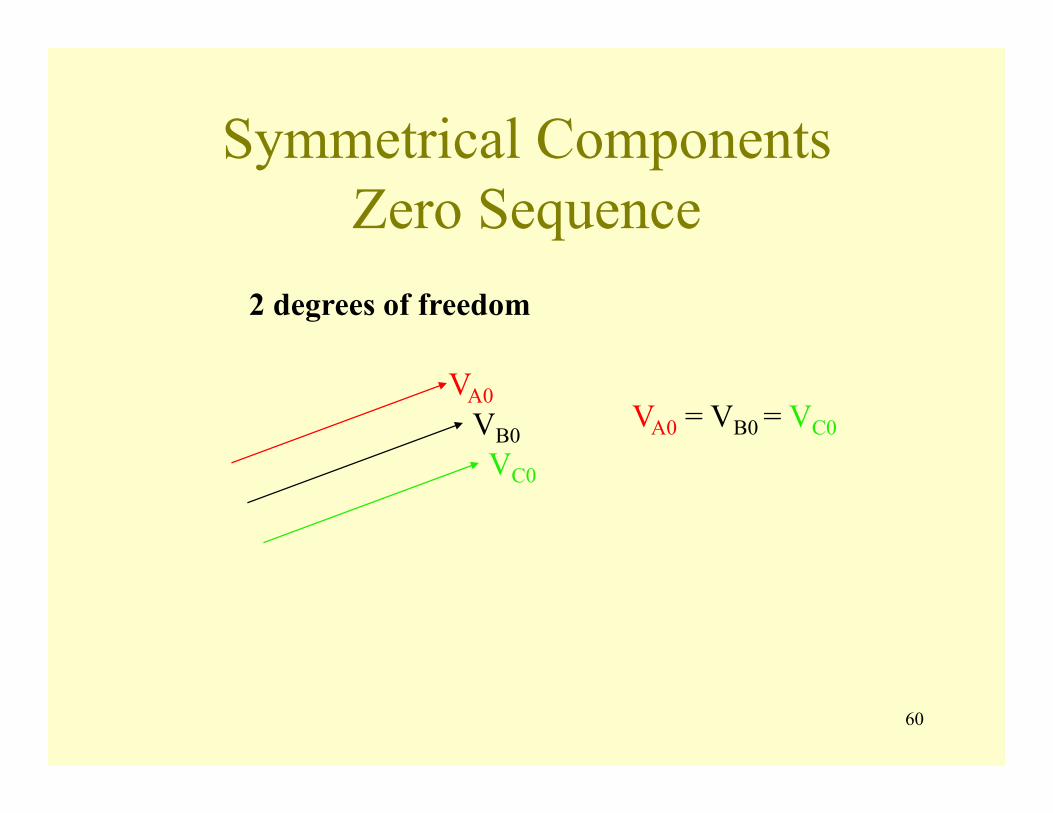
Symmetrical ComponentsZero Sequence
2 degrees of freedom
VA0VB0VC0
VA0 = VB0 = VC0
61
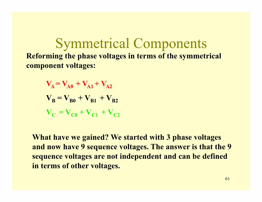
Symmetrical ComponentsReforming the phase voltages in terms of the symmetrical component voltages:
VA = VA0 + VA1 + VA2
VB = VB0 + VB1 + VB2
VC = VC0 + VC1 + VC2
What have we gained? We started with 3 phase voltages and now have 9 sequence voltages. The answer is that the 9 sequence voltages are not independent and can be defined in terms of other voltages.

62
Symmetrical ComponentsRewriting the sequence voltages in term of the Phase A sequence voltages:
VA = VA0 + VA1 +VA2VB = VA0 + a2 VA1 + aVA2VC = VA0 + aVA1 +a2 VA2
VA = V0 + V1 +V2VB = V0 + a2 V1 + aV2VC = V0 + aV1 +a2 V2
Drop A
Suggests matrix notation:
VA 1 1 1 V0
VB 1 a2 a V1
VC 1 a a2 V2
=
[VP] = [A] [VS]
63
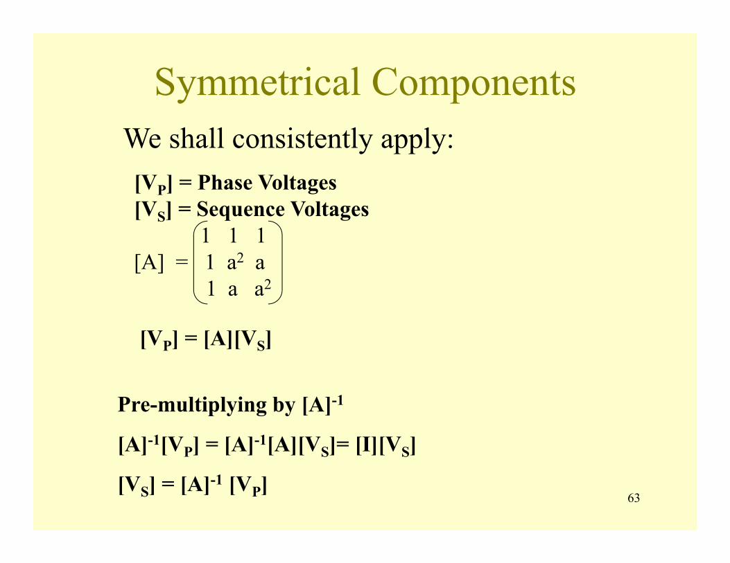
Symmetrical ComponentsWe shall consistently apply:[VP] = Phase Voltages[VS] = Sequence Voltages
1 1 1[A] = 1 a2 a
1 a a2
[VP] = [A][VS]
Pre-multiplying by [A]-1
[A]-1[VP] = [A]-1[A][VS]= [I][VS]
[VS] = [A]-1 [VP]
64
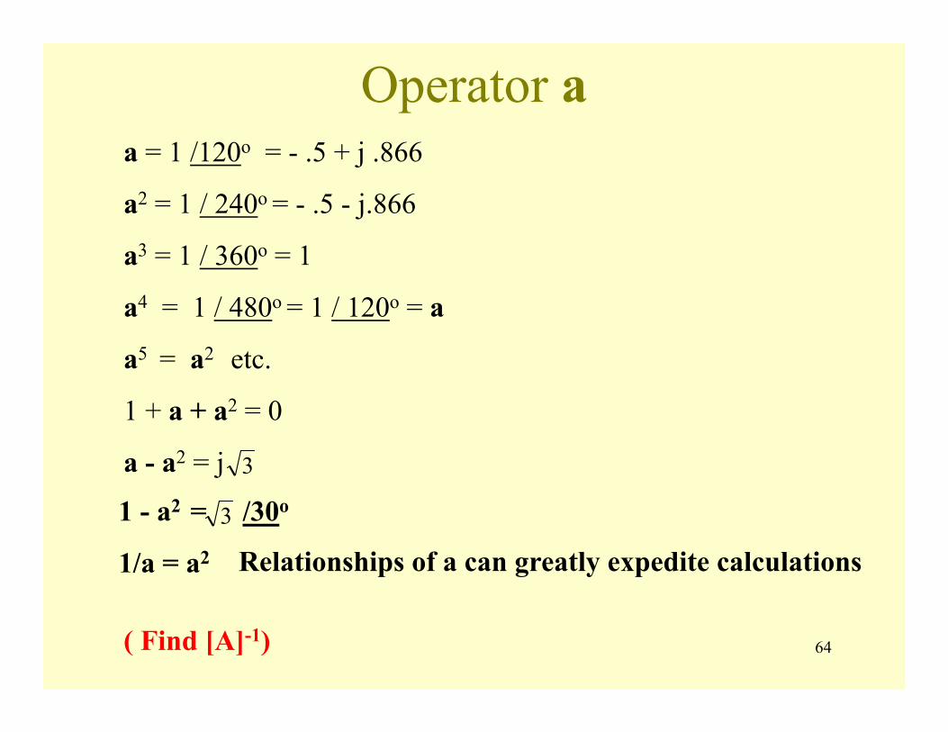
Operator aa = 1 /120o = - .5 + j .866
a2 = 1 / 240o = - .5 - j.866
a3 = 1 / 360o = 1
a4 = 1 / 480o = 1 / 120o = a
a5 = a2 etc.
1 + a + a2 = 0
a - a2 = j 3
1 - a2 = /30o
1/a = a2
3
Relationships of a can greatly expedite calculations
( Find [A]-1)

65
Inverse of A
[ ]⎥⎥⎥
⎦
⎤
⎢⎢⎢
⎣
⎡=
2
2
11
111
aaaaA
Step 1: Transpose
[ ]⎥⎥⎥
⎦
⎤
⎢⎢⎢
⎣
⎡=
2
2
11
111
aaaaA T
Step 2: Replace each element by its minor
⎥⎥⎥
⎦
⎤
⎢⎢⎢
⎣
⎡
−−−−−−−−−
1111
22
22
222
aaaaaaaa
aaaaaa1
1
2
3
2 3
66
⎥⎥⎥
⎦
⎤
⎢⎢⎢
⎣
⎡
−−−−−−−−−
1111
22
22
222
aaaaaaaa
aaaaaa1
1
2
3
2 3
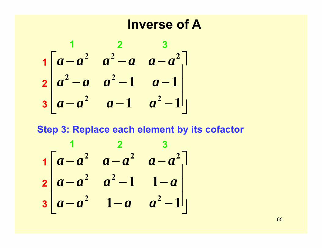
Inverse of A
Step 3: Replace each element by its cofactor
⎥⎥⎥
⎦
⎤
⎢⎢⎢
⎣
⎡
−−−−−−−−−
1111
22
22
222
aaaaaaaaaaaaaa1
1
2
3
2 3

67
Inverse of A
⎥⎥⎥
⎦
⎤
⎢⎢⎢
⎣
⎡
−−−−−−−−−
1111
22
22
222
aaaaaaaaaaaaaa1
1
2
3
2 3
Step 4: Divide by Determinant
[ ]⎥⎥⎥
⎦
⎤
⎢⎢⎢
⎣
⎡=
2
2
11
111
aaaaA
)(3)(1)(1)(1 2222 aaaaaaaaD −=−+−+−=
aaaa
aaa
aa
aaa
=−−
=−−
⎟⎠⎞
⎜⎝⎛=
−−
1111
2
2
2
2
2
2
22
11111 a
aaa
aaaa
==−−
⎟⎠⎞
⎜⎝⎛=
−−
68
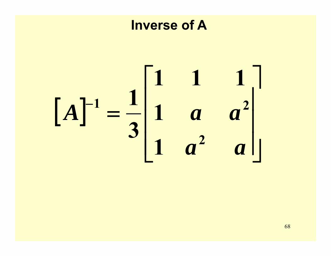
Inverse of A
[ ]⎥⎥⎥
⎦
⎤
⎢⎢⎢
⎣
⎡=−
aaaaA
2
21
11
111
31
69
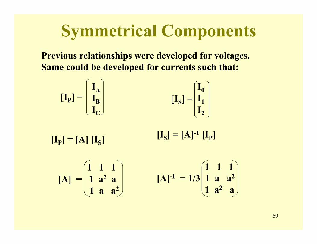
Symmetrical ComponentsPrevious relationships were developed for voltages. Same could be developed for currents such that:
IAIBIC
[IP] =I0I1I2
[IS] =
[IP] = [A] [IS] [IS] = [A]-1 [IP]
1 1 1[A] = 1 a2 a
1 a a2
1 1 1[A]-1 = 1/3 1 a a2
1 a2 a
70
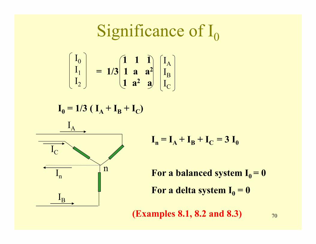
Significance of I0
IAIBIC
I0I1I2
1 1 1= 1/3 1 a a2
1 a2 a
I0 = 1/3 ( IA + IB + IC)
n
IA
IB
IC
In
In = IA + IB + IC = 3 I0
For a balanced system I0 = 0
For a delta system I0 = 0
(Examples 8.1, 8.2 and 8.3)
71
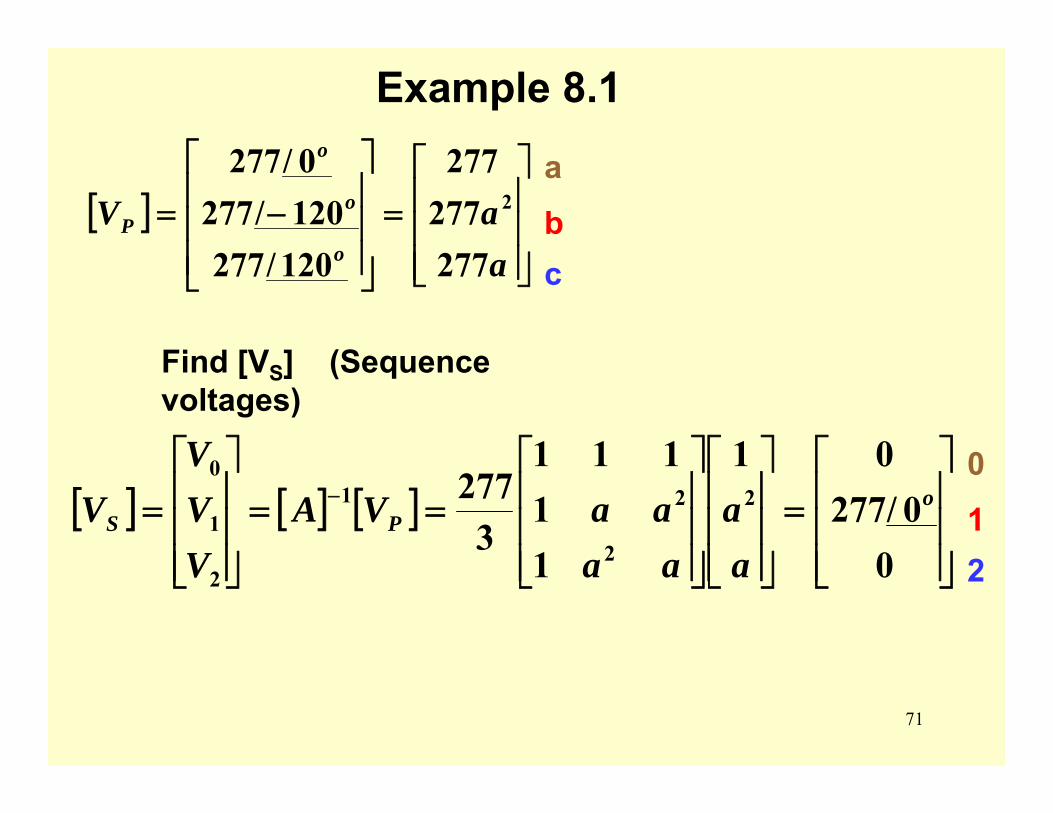
Example 8.1
[ ]⎥⎥⎥
⎦
⎤
⎢⎢⎢
⎣
⎡=
⎥⎥⎥
⎦
⎤
⎢⎢⎢
⎣
⎡
−=aaV
o
o
o
P
277277
277
120/277120/2770/277
2
[ ] [ ] [ ]⎥⎥⎥
⎦
⎤
⎢⎢⎢
⎣
⎡=
⎥⎥⎥
⎦
⎤
⎢⎢⎢
⎣
⎡
⎥⎥⎥
⎦
⎤
⎢⎢⎢
⎣
⎡==
⎥⎥⎥
⎦
⎤
⎢⎢⎢
⎣
⎡= −
00/277
01
11
111
3277 2
2
21
2
1
0o
PS
aa
aaaaVA
VVV
V0
12
Find [VS] (Sequence voltages)
a
bc
72
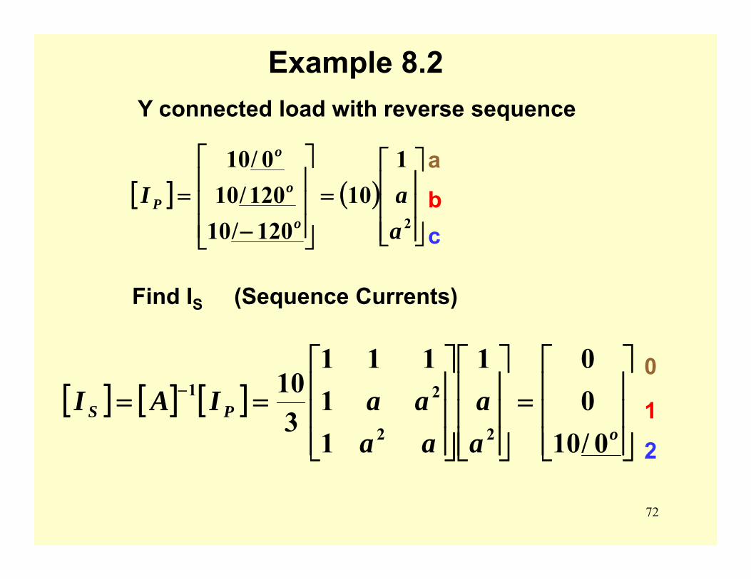
Example 8.2Y connected load with reverse sequence
[ ] ( )⎥⎥⎥
⎦
⎤
⎢⎢⎢
⎣
⎡=
⎥⎥⎥
⎦
⎤
⎢⎢⎢
⎣
⎡
−=
2
110
120/10120/10
0/10
aaI
o
o
o
P
a
bc
Find IS (Sequence Currents)
[ ] [ ] [ ]⎥⎥⎥
⎦
⎤
⎢⎢⎢
⎣
⎡=
⎥⎥⎥
⎦
⎤
⎢⎢⎢
⎣
⎡
⎥⎥⎥
⎦
⎤
⎢⎢⎢
⎣
⎡== −
oPS
aa
aaaaIAI
0/10001
11
111
310
22
210
1
2
73
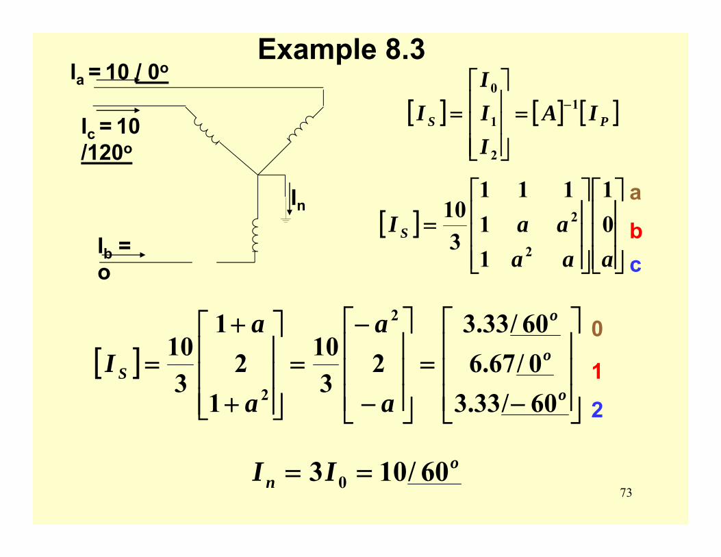
Example 8.3Ia = 10 / 0o
Ic = 10 /120o
Ib = o
In
[ ] [ ] [ ]PS IAIII
I 1
2
1
0−=
⎥⎥⎥
⎦
⎤
⎢⎢⎢
⎣
⎡=
[ ]⎥⎥⎥
⎦
⎤
⎢⎢⎢
⎣
⎡
⎥⎥⎥
⎦
⎤
⎢⎢⎢
⎣
⎡=
aaaaaI S 0
1
11
111
310
2
2
[ ]⎥⎥⎥
⎦
⎤
⎢⎢⎢
⎣
⎡
−=
⎥⎥⎥
⎦
⎤
⎢⎢⎢
⎣
⎡
−
−=
⎥⎥⎥
⎦
⎤
⎢⎢⎢
⎣
⎡
+
+=
o
o
o
S
a
a
a
aI
60/33.30/67.6
60/33.32
310
12
1
310
2
2
0
1
2
on II 60/103 0 ==
a
bc
74
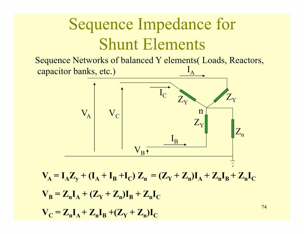
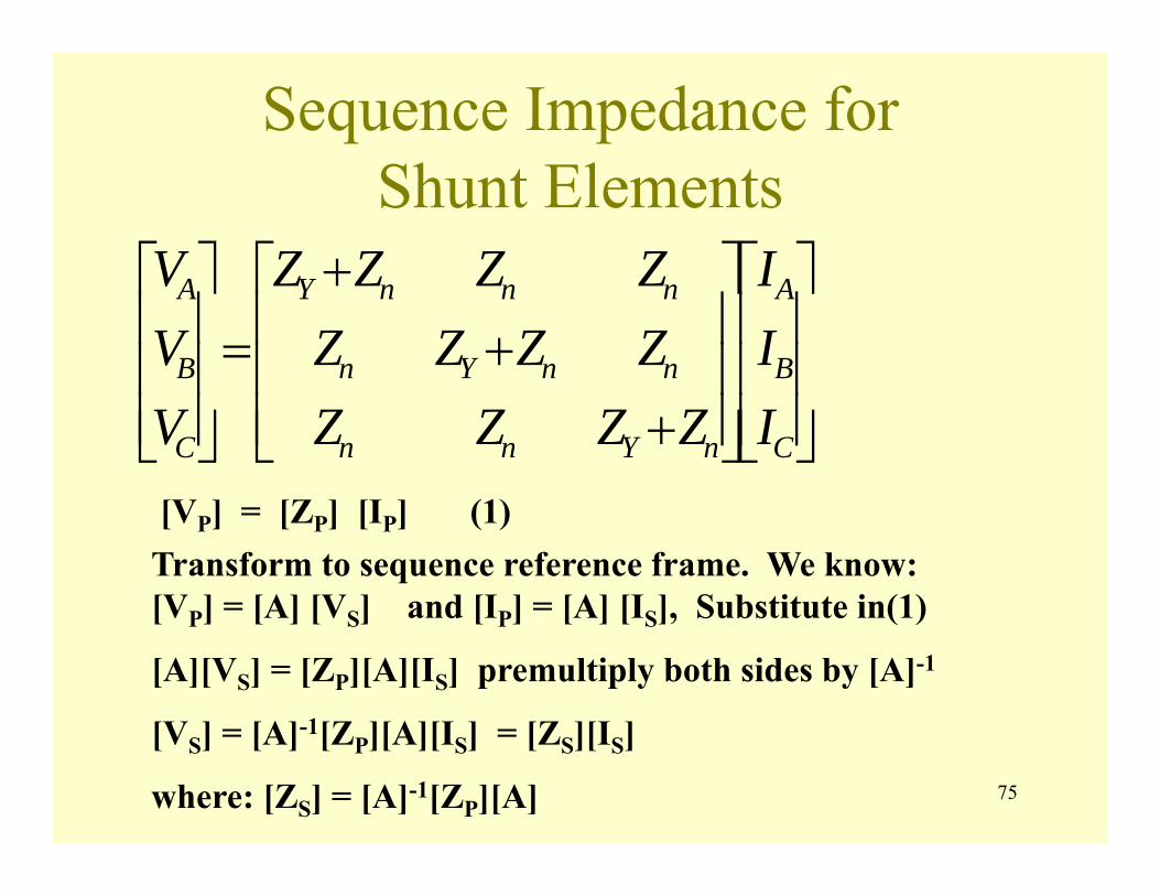
Sequence Impedance for Shunt Elements
Sequence Networks of balanced Y elements( Loads, Reactors,capacitor banks, etc.)
VA = IAZy + (IA + IB +IC) Zn = (ZY + Zn)IA + ZnIB + ZnIC
VB = ZnIA + (ZY + Zn)IB + ZnIC
VC = ZnIA + ZnIB +(ZY + Zn)IC
n
IB
IC
.
IA
VB
VA VC
ZYZY
ZYZn
75
Sequence Impedance for Shunt Elements
⎥⎥⎥
⎦
⎤
⎢⎢⎢
⎣
⎡
⎥⎥⎥
⎦
⎤
⎢⎢⎢
⎣
⎡
++
+=⎥⎥⎥
⎦
⎤
⎢⎢⎢
⎣
⎡
C
B
A
nYnn
nnYn
nnnY
C
B
A
III
ZZZZZZZZZZZZ
VVV
[VP] = [ZP] [IP] (1)Transform to sequence reference frame. We know: [VP] = [A] [VS] and [IP] = [A] [IS], Substitute in(1)
[A][VS] = [ZP][A][IS] premultiply both sides by [A]-1
[VS] = [A]-1[ZP][A][IS] = [ZS][IS]
where: [ZS] = [A]-1[ZP][A]

76
Sequence Impedance forShunt Elements
[ZS] =⎥⎥⎥
⎦
⎤
⎢⎢⎢
⎣
⎡
⎥⎥⎥
⎦
⎤
⎢⎢⎢
⎣
⎡
++
+
⎥⎥⎥
⎦
⎤
⎢⎢⎢
⎣
⎡=⎥⎥⎥
⎦
⎤
⎢⎢⎢
⎣
⎡
2
2
2
2
222120
121110
020100
11
111
11
111
31
aaaa
ZZZZZZZZZZZZ
aaaa
ZZZZZZZZZ
nYnn
nnYn
nnnY
[ ]⎥⎥⎥
⎦
⎤
⎢⎢⎢
⎣
⎡ +=
Y
Y
nY
S
ZZ
ZZZ
000003 0
1
2
0 1 2
77
Sequence Impedance for Shunt Elements
⎥⎥⎥
⎦
⎤
⎢⎢⎢
⎣
⎡
⎥⎥⎥
⎦
⎤
⎢⎢⎢
⎣
⎡ +=
⎥⎥⎥
⎦
⎤
⎢⎢⎢
⎣
⎡
2
1
0
2
1
0
0000003
III
ZZ
ZZ
VVV
Y
Y
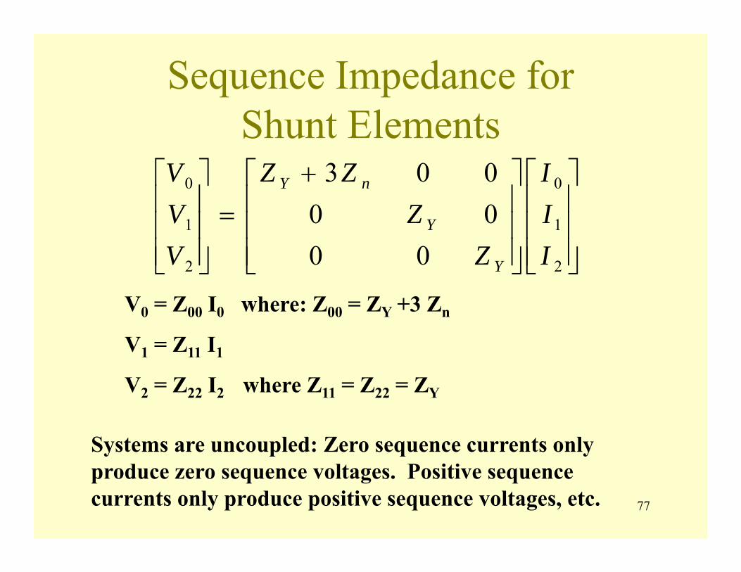
nY
V0 = Z00 I0 where: Z00 = ZY +3 Zn
V1 = Z11 I1
V2 = Z22 I2 where Z11 = Z22 = ZY
Systems are uncoupled: Zero sequence currents only produce zero sequence voltages. Positive sequence currents only produce positive sequence voltages, etc.

78
Sequence Impedance forShunt Elements
We can form sequence circuits which represent the equations:
ZY
3 Zn
ZY
ZY
V0
V1
V2
I0
I1
I2
Zero sequence circuit Znonly in zero Sequence No neutral: Zn = infinity Solid ground: Zn = 0
Positive sequence circuit
Negative sequence circuit

79
Sequence Impedance forShunt Elements
Delta connected shunt element
ZYV0
V1
V2
I0
I1
I2
open
ZΔ/3
ZΔ/3
Sequence circuits.A
B
C
IA
IB
IC
ZΔ
ZΔ ZΔ
80
Sequence Impedance forShunt Elements
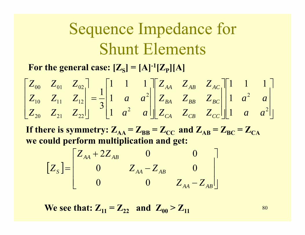
For the general case: [ZS] = [A]-1[ZP][A]
⎥⎥⎥
⎦
⎤
⎢⎢⎢
⎣
⎡
⎥⎥⎥
⎦
⎤
⎢⎢⎢
⎣
⎡
⎥⎥⎥
⎦
⎤
⎢⎢⎢
⎣
⎡=
⎥⎥⎥
⎦
⎤
⎢⎢⎢
⎣
⎡
2
2
2
2
222120
121110
020100
11
111
11
111
31
aaaa
ZZZZZZZZZ
aaaa
ZZZZZZZZZ
CCCBCA
BCBBBA
ACABAA
If there is symmetry: ZAA = ZBB = ZCC and ZAB = ZBC = ZCA we could perform multiplication and get:
[ ]⎥⎥⎥
⎦
⎤
⎢⎢⎢
⎣
⎡
−−
+=
ABAA
ABAA
ABAA
S
ZZZZ
ZZZ
0000002
We see that: Z11 = Z22 and Z00 > Z11
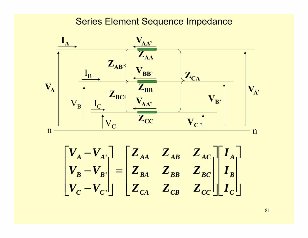
81
ZAB
ZBC
ZAA
ZCC
VAA’
ZBB
VAA’
VBB’
IA
IB
IC
VA
VB
VC
ZCA
VA’VB’
VC ’
⎥⎥⎥
⎦
⎤
⎢⎢⎢
⎣
⎡
⎥⎥⎥
⎦
⎤
⎢⎢⎢
⎣
⎡=
⎥⎥⎥
⎦
⎤
⎢⎢⎢
⎣
⎡
−−−
C
B
A
CCCBCA
BCBBBA
ACABAA
CC
BB
AA
III
ZZZZZZZZZ
VVVVVV
'
'
'
n n
Series Element Sequence Impedance
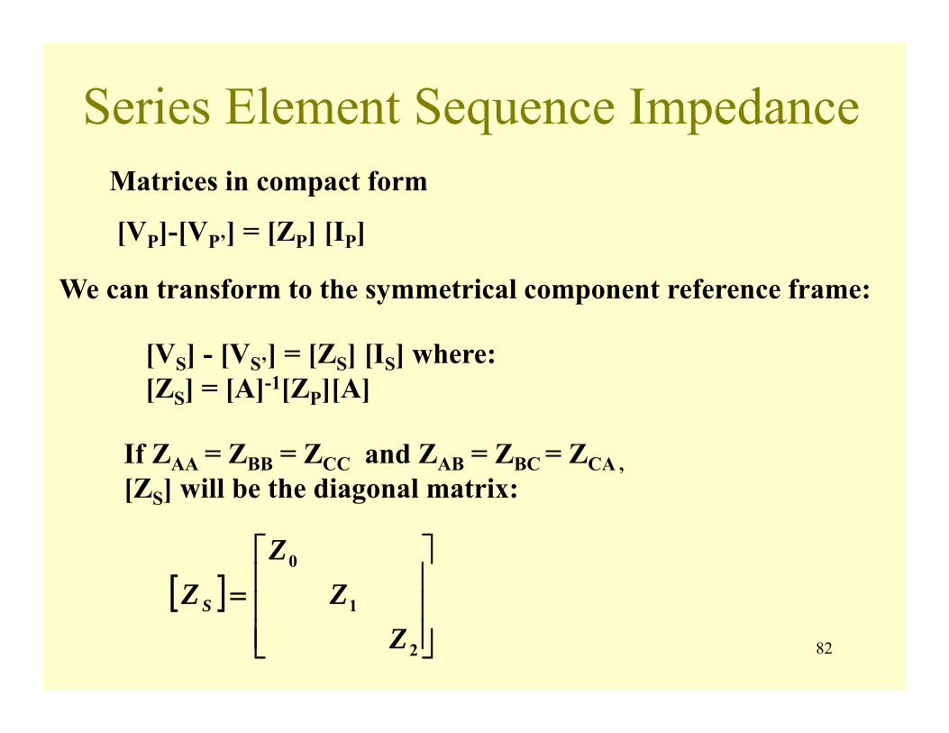
82
Series Element Sequence ImpedanceMatrices in compact form
[VP]-[VP’] = [ZP] [IP]
We can transform to the symmetrical component reference frame:
[VS] - [VS’] = [ZS] [IS] where: [ZS] = [A]-1[ZP][A]
If ZAA = ZBB = ZCC and ZAB = ZBC = ZCA , [ZS] will be the diagonal matrix:
[ ]⎥⎥⎥
⎦
⎤
⎢⎢⎢
⎣
⎡=
2
1
0
ZZ
ZZS

83
Series Element Sequence Impedance
The sequence circuits for series elements are:
Z0V0 V0’I0
o n0
Z1V1 V1’I1
o n1
Z2V2 V2’I2
o n2
84
Series Element Sequence Impedance
We have quickly covered the calculation of Positive and Negative sequence parameters for 3-phase lines. To determine the zero sequence impedance we need to take the effect of the earth into account. This is done by using Carson’s Method which treats the earth as an equivalent conductor.
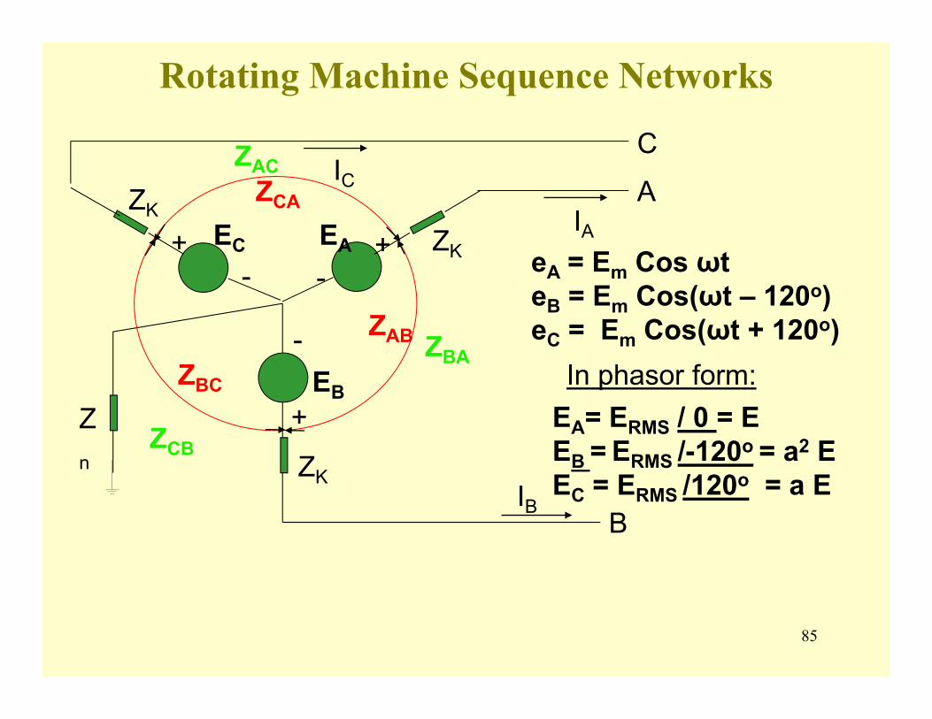
85
Rotating Machine Sequence Networks
A
B
C
ZK
ZK
ZK
-
- -
+
+ +
EB
EAEC
ICIA
IB
Zn
ZAB
ZBC
ZCA
ZCB
ZBA
ZAC
eA = Em Cos ωt eB = Em Cos(ωt – 120o)eC = Em Cos(ωt + 120o)
In phasor form:EA= ERMS / 0 = E EB = ERMS /-120o = a2 E EC = ERMS /120o = a E

86
Rotating Machine Sequence Networks
[ ]⎥⎥⎥
⎦
⎤
⎢⎢⎢
⎣
⎡=
aEEa
EEPg
2EA= ERMS / 0 = E EB = ERMS /-120o = a2 E EC = ERMS /120o = a E
or
[ ] [ ] [ ]⎥⎥⎥
⎦
⎤
⎢⎢⎢
⎣
⎡=
⎥⎥⎥
⎦
⎤
⎢⎢⎢
⎣
⎡
⎥⎥⎥
⎦
⎤
⎢⎢⎢
⎣
⎡== −
0
0
11
111
31 2
2
21 EaE
EaE
aaaaEAE PgSg
Therefore, only the positive sequence system has a generator voltage source.
0
12
abc
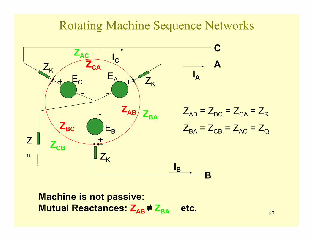
87
Rotating Machine Sequence Networks
A
B
C
ZK
ZK
ZK
-
- -
+
+ +
EB
EAEC
ICIA
IB
Zn
ZAB
ZBC
ZCA
ZCB
ZBA
ZAC
Machine is not passive: Mutual Reactances: ZAB ≠ ZBA , etc.
ZAB = ZBC = ZCA = ZR
ZBA = ZCB = ZAC = ZQ
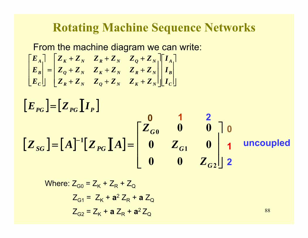
88
Rotating Machine Sequence Networks
⎥⎥⎥
⎦
⎤
⎢⎢⎢
⎣
⎡
⎥⎥⎥
⎦
⎤
⎢⎢⎢
⎣
⎡
+++++++++
=⎥⎥⎥
⎦
⎤
⎢⎢⎢
⎣
⎡
C
B
A
NKNQNR
NRNKNQ
NQNRNK
C
B
A
III
ZZZZZZZZZZZZZZZZZZ
EEE
[ ] [ ][ ]PPGPG IZE =
[ ] [ ] [ ][ ]⎥⎥⎥
⎦
⎤
⎢⎢⎢
⎣
⎡== −
2
1
01
000000
G
G
G
PGSG
ZZ
ZAZAZ
From the machine diagram we can write:
Where: ZG0 = ZK + ZR + ZQ
ZG1 = ZK + a2 ZR + a ZQ
ZG2 = ZK + a ZR + a2 ZQ
uncoupled0
12
0 1 2

89
Rotating Machine Sequence NetworksGenerator sequence circuits are uncoupled
3Zn
ZG0
I0
V0
EG1-
+ ZG1 I1V1
ZG2 I2V2
Generator Terminal Voltages
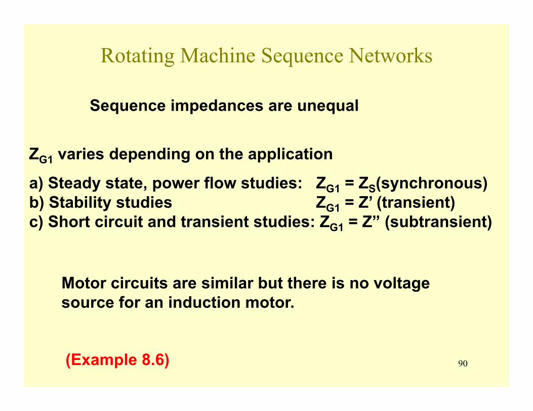
90
Rotating Machine Sequence Networks
Sequence impedances are unequal
ZG1 varies depending on the application
a) Steady state, power flow studies: ZG1 = ZS(synchronous) b) Stability studies ZG1 = Z’ (transient) c) Short circuit and transient studies: ZG1 = Z” (subtransient)
Motor circuits are similar but there is no voltage source for an induction motor.
(Example 8.6)
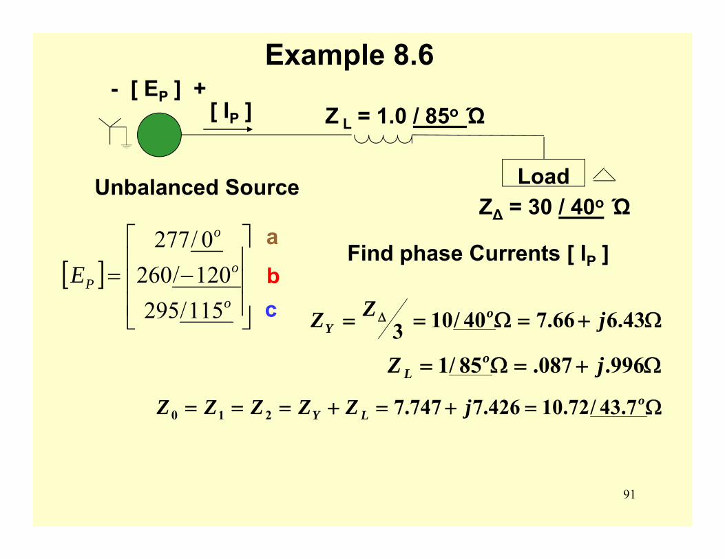
91
Example 8.6- [ EP ] +
[ IP ] Z L = 1.0 / 85o Ώ
LoadZ∆ = 30 / 40o Ώ
Unbalanced Source
[ ]⎥⎥⎥
⎦
⎤
⎢⎢⎢
⎣
⎡
−=o
o
o
PE115/295120/2600/277 a
bc
Find phase Currents [ IP ]
Ω+=Ω== Δ 43.666.740/103 jZZ oY
Ω+=Ω= 996.087.85/1 jZ oL
Ω=+=+=== oLY jZZZZZ 7.43/72.10426.7747.7210
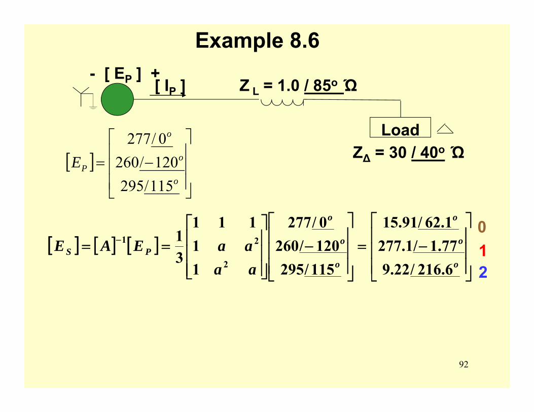
92
Example 8.6- [ EP ] +
[ IP ] Z L = 1.0 / 85o Ώ
LoadZ∆ = 30 / 40o Ώ[ ]
⎥⎥⎥
⎦
⎤
⎢⎢⎢
⎣
⎡
−=o
o
o
PE115/295120/2600/277
[ ] [ ] [ ]⎥⎥⎥
⎦
⎤
⎢⎢⎢
⎣
⎡
−=⎥⎥⎥
⎦
⎤
⎢⎢⎢
⎣
⎡
−⎥⎥⎥
⎦
⎤
⎢⎢⎢
⎣
⎡== −
o
o
o
o
o
o
PS
aaaaEAE
6.216/22.977.1/1.2771.62/91.15
115/295120/2600/277
11
111
31
2
21012
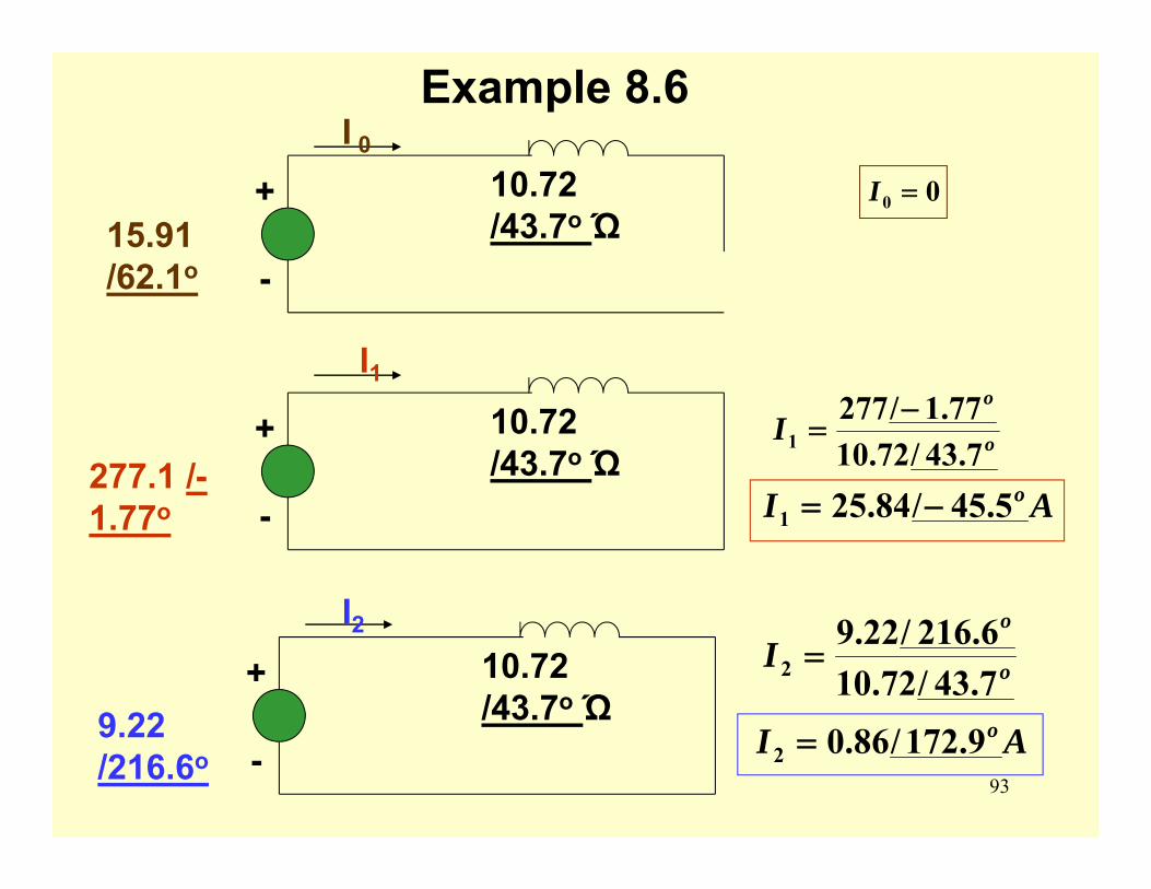
93
Example 8.6
10.72 /43.7o Ώ
-
+15.91 /62.1o
I 0
10.72 /43.7o Ώ
-
+277.1 /-1.77o
I1
10.72 /43.7o Ώ
-
+9.22 /216.6o
I2
00 =I
o
o
I7.43/72.10
77.1/2771
−=
AI o5.45/84.251 −=
o
o
I7.43/72.106.216/22.9
2 =
AI o9.172/86.02 =
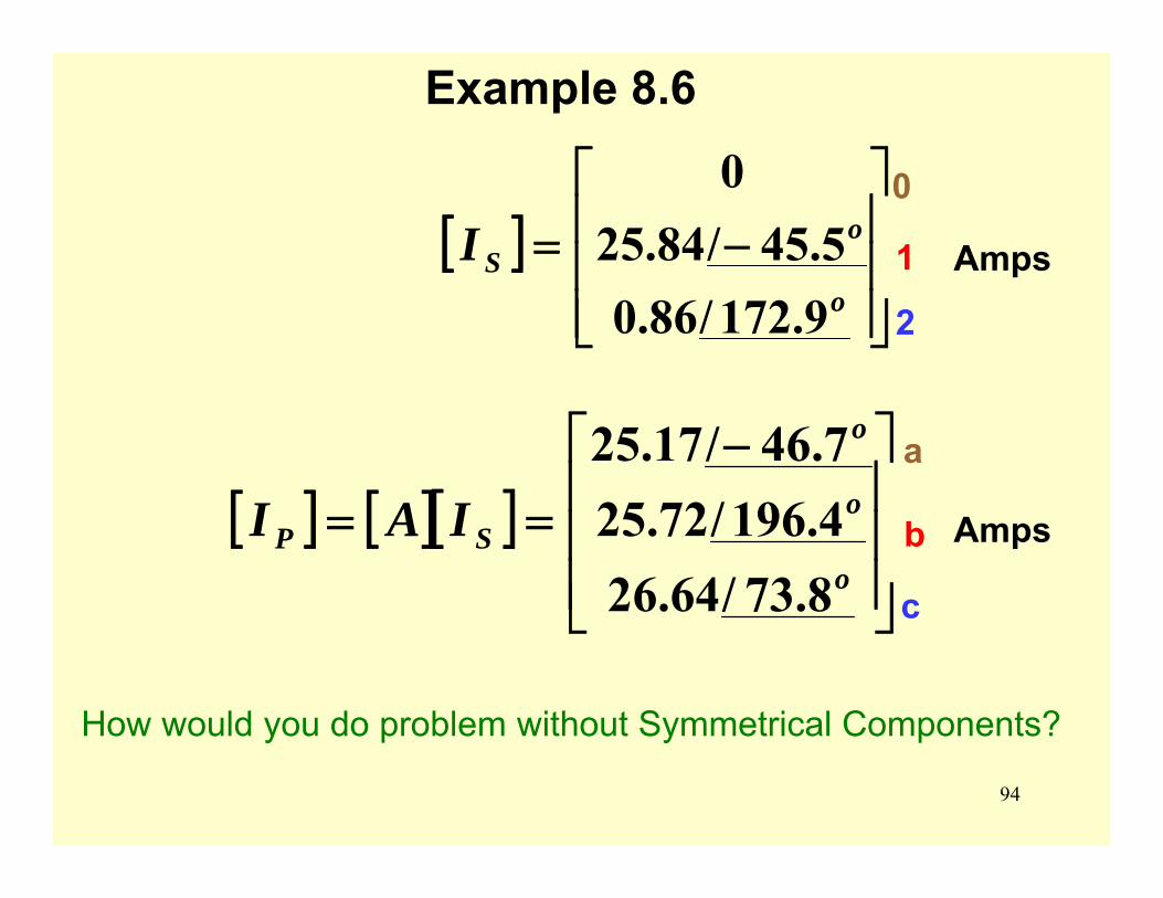
94
Example 8.6
[ ] [ ][ ]⎥⎥⎥
⎦
⎤
⎢⎢⎢
⎣
⎡ −==
o
o
o
SP IAI8.73/64.264.196/72.257.46/17.25
[ ]⎥⎥⎥
⎦
⎤
⎢⎢⎢
⎣
⎡−=
o
oSI
9.172/86.05.45/84.25
0 0
1
2
a
b
c
Amps
Amps
How would you do problem without Symmetrical Components?
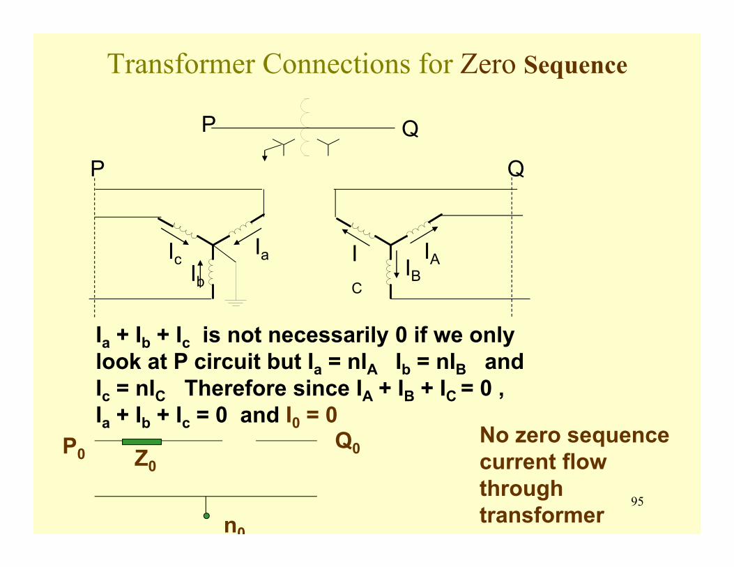
95
Transformer Connections for Zero Sequence
P Q
Ic IaIb
IC
IAIB
P Q
Ia + Ib + Ic is not necessarily 0 if we only look at P circuit but Ia = nIA Ib = nIB and Ic = nIC Therefore since IA + IB + IC = 0 , Ia + Ib + Ic = 0 and I0 = 0
P0Q0Z0
n0
No zero sequence current flow through transformer
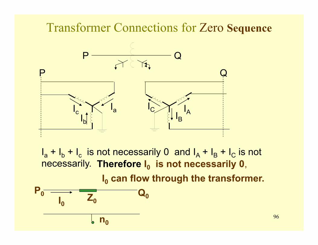
96
Transformer Connections for Zero Sequence
P Q
Ic IaIb
IC IAIB
P Q
Ia + Ib + Ic is not necessarily 0 and IA + IB + IC is not necessarily.
P0 Q0Z0
n0
I0 can flow through the transformer.Therefore I0 is not necessarily 0,
I0
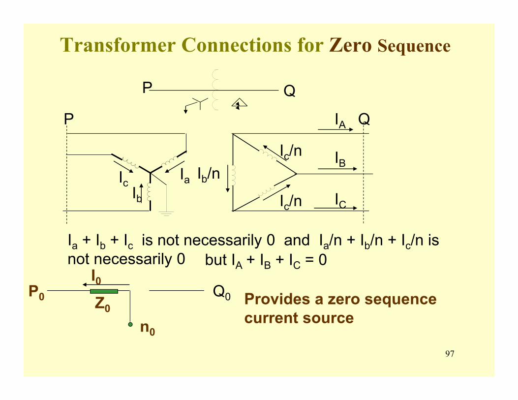
97
Transformer Connections for Zero Sequence
P Q
Ic IaIb IC
IA
IB
P Q
Ia + Ib + Ic is not necessarily 0 and Ia/n + Ib/n + Ic/n is not necessarily 0
P0 Q0Z0
n0
Provides a zero sequence current source
Ib/nIc/n
Ic/n
I0but IA + IB + IC = 0
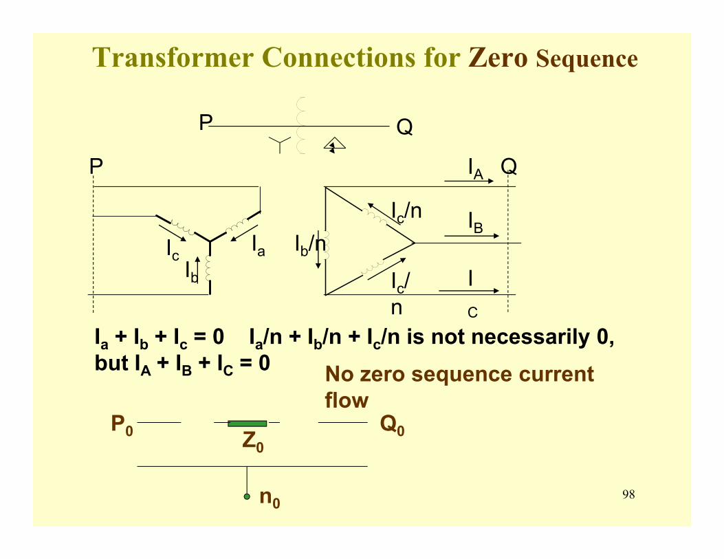
98
Transformer Connections for Zero Sequence
P Q
Ic IaIb I
C
IA
IB
P Q
Ia + Ib + Ic = 0 Ia/n + Ib/n + Ic/n is not necessarily 0, but IA + IB + IC = 0
P0 Q0Z0
n0
No zero sequence current flow
Ib/nIc/n
Ic/n
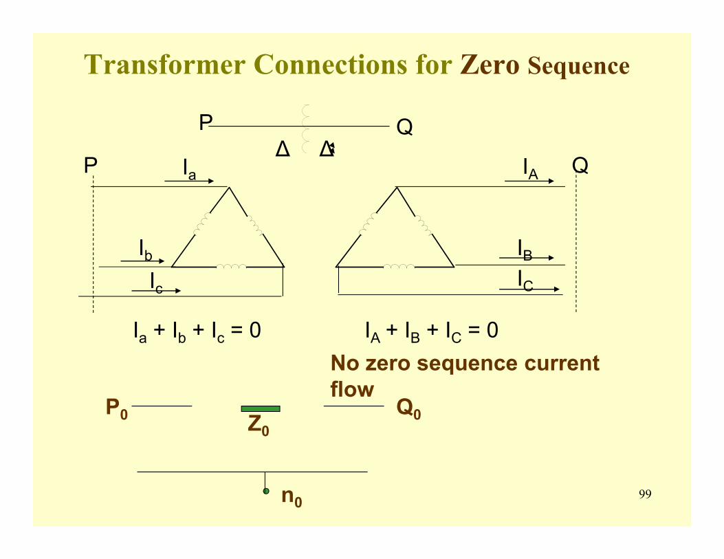
99
Transformer Connections for Zero Sequence
P Q
IC
IA
IB
P Q
Ia + Ib + Ic = 0 IA + IB + IC = 0
P0 Q0Z0
n0
No zero sequence current flow
∆ ∆Ia
IbIc
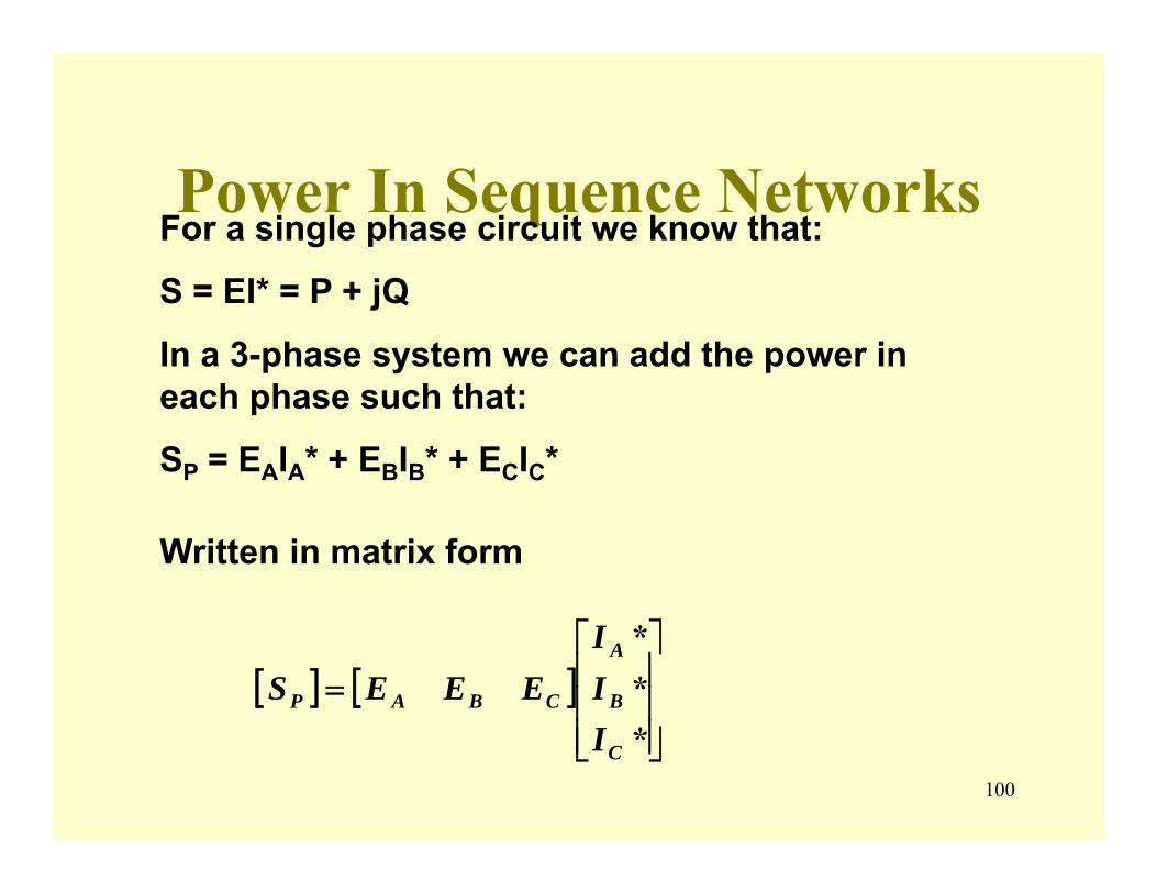
100
Power In Sequence NetworksFor a single phase circuit we know that:
S = EI* = P + jQ
In a 3-phase system we can add the power in each phase such that:
SP = EAIA* + EBIB* + ECIC*
Written in matrix form
[ ] [ ]⎥⎥⎥
⎦
⎤
⎢⎢⎢
⎣
⎡=
***
C
B
A
CBAP
III
EEES
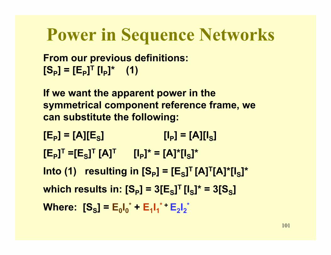
101
Power in Sequence Networks
If we want the apparent power in the symmetrical component reference frame, we can substitute the following:
[EP] = [A][ES] [IP] = [A][IS]
[EP]T =[ES]T [A]T [IP]* = [A]*[IS]*
Into (1) resulting in [SP] = [ES]T [A]T[A]*[IS]*
which results in: [SP] = 3[ES]T [IS]* = 3[SS]
Where: [SS] = E0I0* + E1I1* + E2I2*
From our previous definitions: [SP] = [EP]T [IP]* (1)
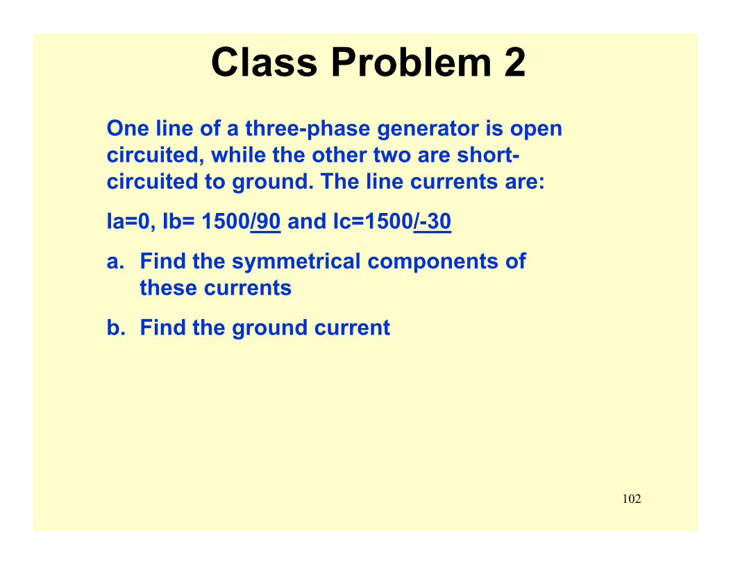
102
Class Problem 2One line of a three-phase generator is open circuited, while the other two are short-circuited to ground. The line currents are:
Ia=0, Ib= 1500/90 and Ic=1500/-30
a. Find the symmetrical components of these currents
b. Find the ground current
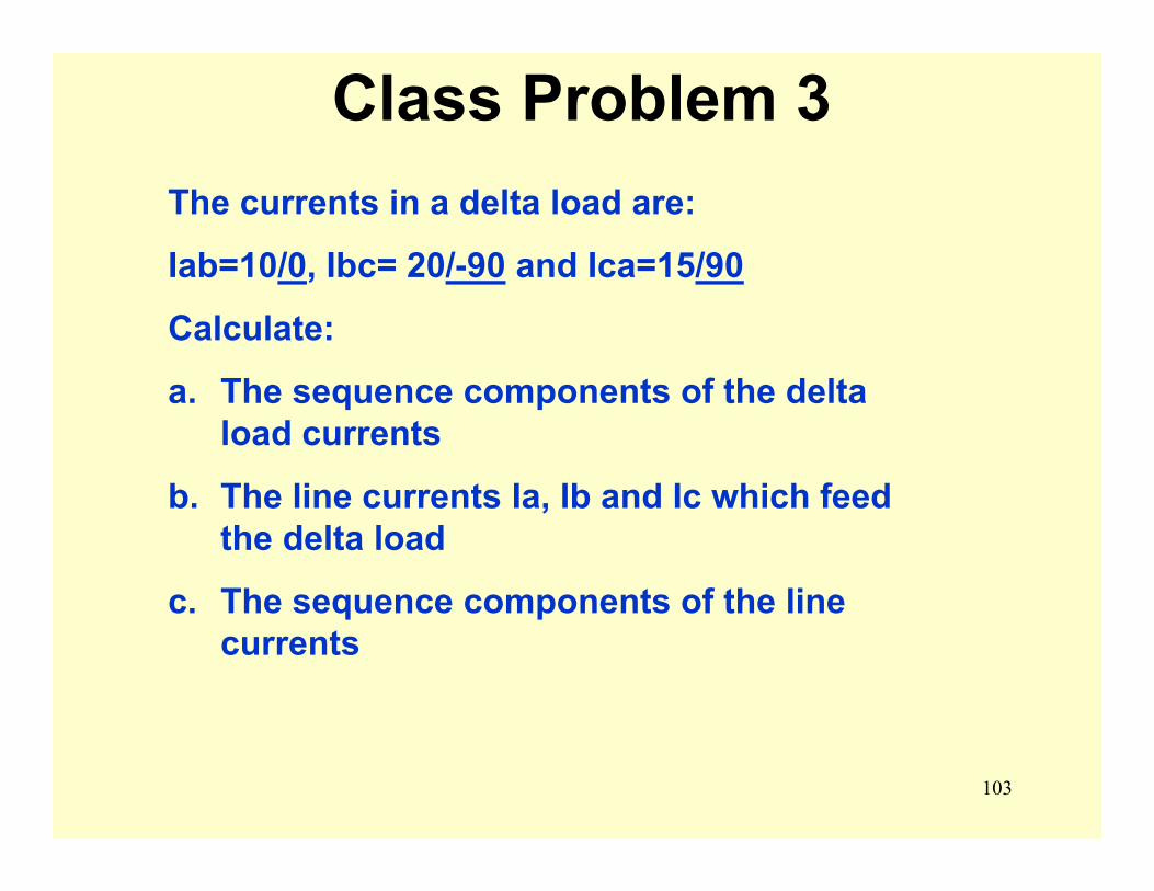
103
Class Problem 3The currents in a delta load are:
Iab=10/0, Ibc= 20/-90 and Ica=15/90
Calculate:
a. The sequence components of the delta load currents
b. The line currents Ia, Ib and Ic which feed the delta load
c. The sequence components of the line currents
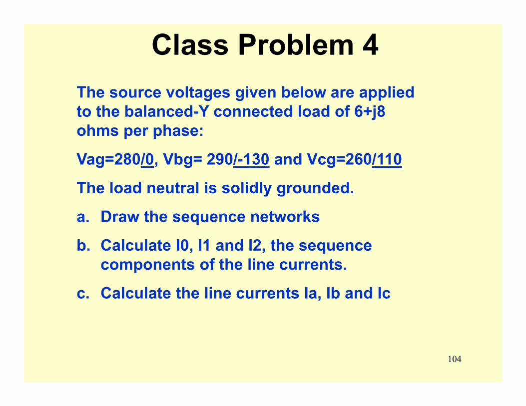
104
Class Problem 4The source voltages given below are applied to the balanced-Y connected load of 6+j8 ohms per phase:
Vag=280/0, Vbg= 290/-130 and Vcg=260/110
The load neutral is solidly grounded.
a. Draw the sequence networks
b. Calculate I0, I1 and I2, the sequence components of the line currents.
c. Calculate the line currents Ia, Ib and Ic
105
Unsymmetrical Faults
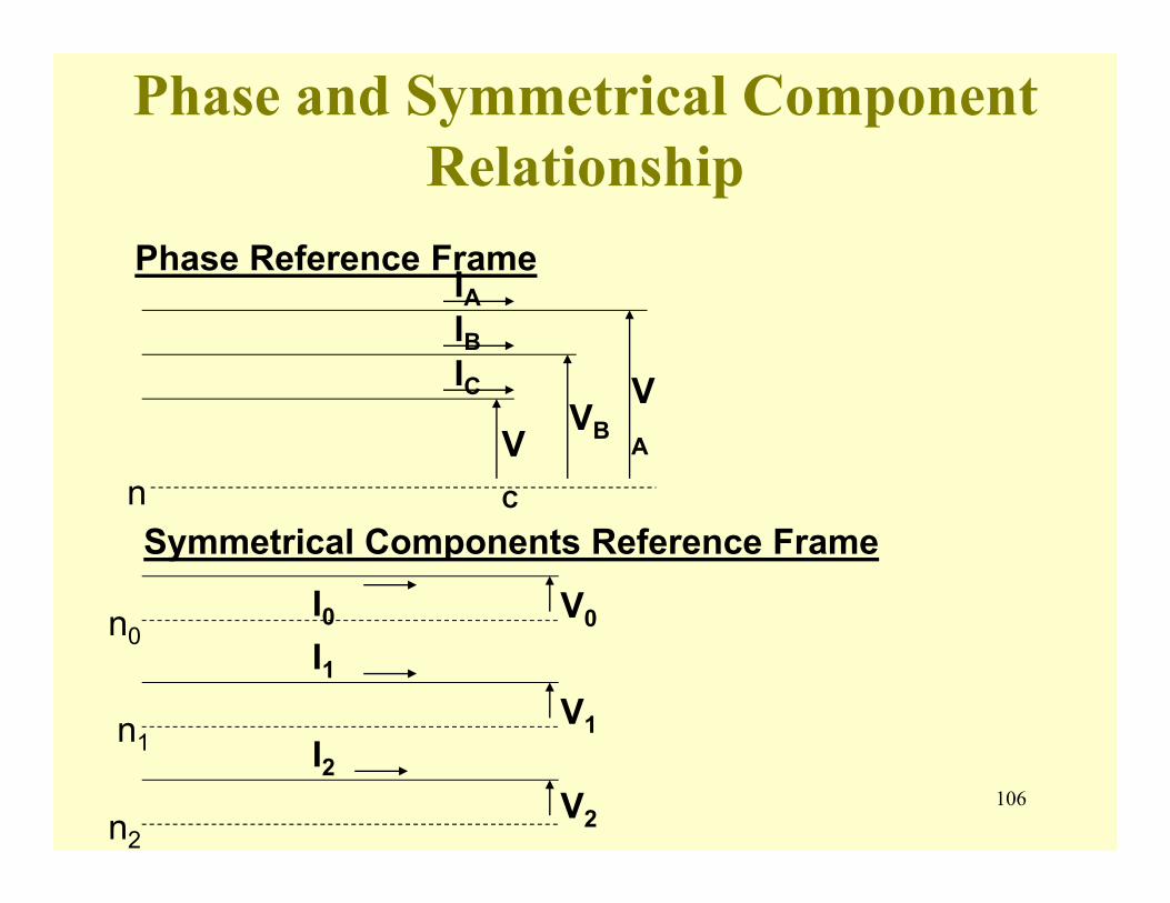
106
Phase and Symmetrical Component Relationship
Phase Reference FrameIAIBIC
nVC
VBVA
Symmetrical Components Reference Frame
I0I1
I2
V0
V1
V2
n0
n1
n2
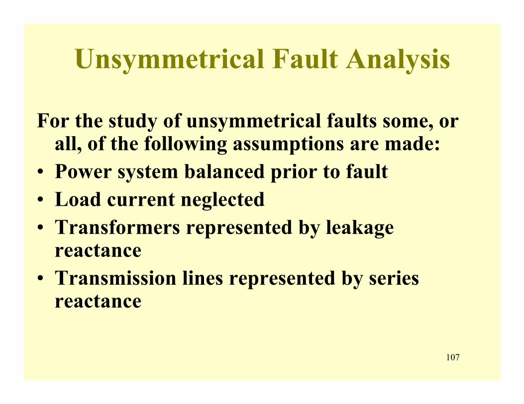
107
Unsymmetrical Fault Analysis
For the study of unsymmetrical faults some, or all, of the following assumptions are made:
• Power system balanced prior to fault• Load current neglected• Transformers represented by leakage
reactance• Transmission lines represented by series
reactance
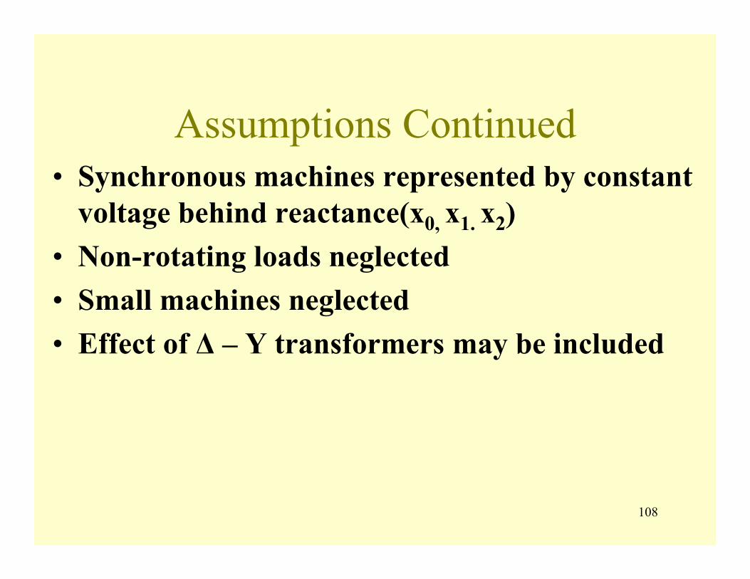
108
Assumptions Continued• Synchronous machines represented by constant
voltage behind reactance(x0, x1. x2)• Non-rotating loads neglected• Small machines neglected• Effect of Δ – Y transformers may be included
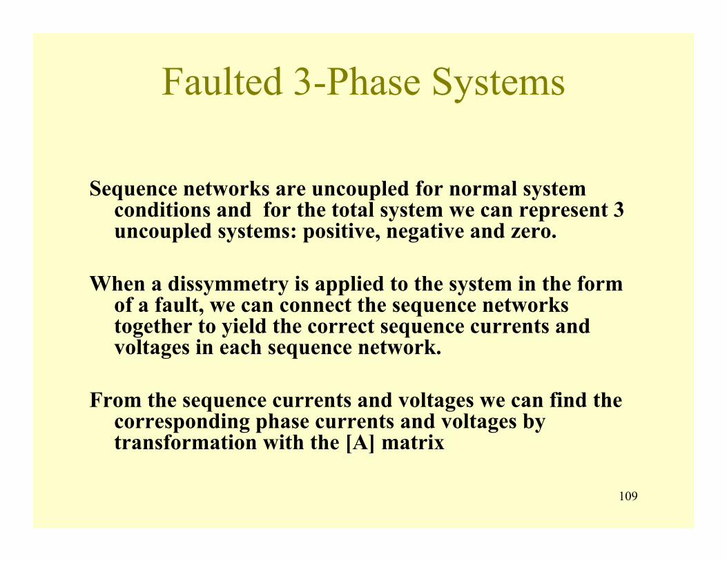
109
Faulted 3-Phase Systems
Sequence networks are uncoupled for normal system conditions and for the total system we can represent 3 uncoupled systems: positive, negative and zero.
When a dissymmetry is applied to the system in the form of a fault, we can connect the sequence networks together to yield the correct sequence currents and voltages in each sequence network.
From the sequence currents and voltages we can find the corresponding phase currents and voltages by transformation with the [A] matrix
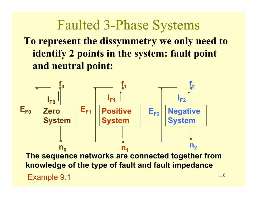
110
Faulted 3-Phase SystemsTo represent the dissymmetry we only need to
identify 2 points in the system: fault point and neutral point:
Zero System
Positive System
Negative System
f0 f1 f2
n0 n1n2
IF0IF1 IF2
EF0 EF1 EF2
The sequence networks are connected together from knowledge of the type of fault and fault impedanceExample 9.1
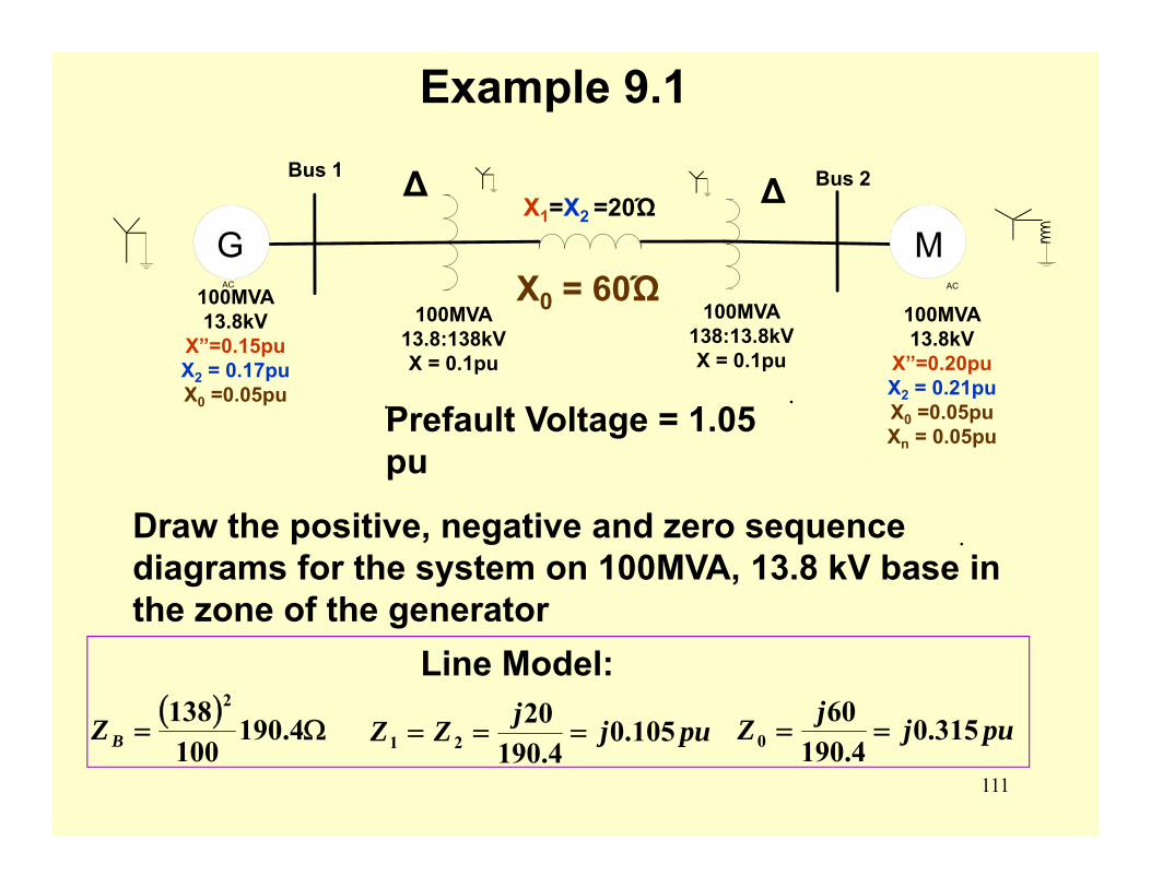
111
.
AC
Bus 1
AC
Bus 2X1=X2 =20Ώ
. .
∆ ∆
100MVA 13.8kV
X”=0.15puX2 = 0.17puX0 =0.05pu
100MVA 13.8:138kV X = 0.1pu
100MVA 138:13.8kV X = 0.1pu
100MVA 13.8kV
X”=0.20puX2 = 0.21puX0 =0.05puXn = 0.05pu
Example 9.1
G M
Prefault Voltage = 1.05 pu
Draw the positive, negative and zero sequence diagrams for the system on 100MVA, 13.8 kV base in the zone of the generator
Line Model:
X0 = 60Ώ
( )Ω= 4.190
100138 2
BZ pujjZZ 105.04.190
2021 === pujjZ 315.0
4.19060
0 ==

112
AC AC
.
AC AC
j.15
-
+
J0.1 J0.105 J0.1
J0.2.
-
+
1 2
1.05 / 0o 1.05 / 0o
n1
AC AC
j.17
J0.1 J0.105 J0.1
J0.21.
1 2
n2
AC AC
.
AC AC
.AC
j.05J0.1
J0.315
J0.1J0.1.
1 2
j.15
n0
Example 9.1
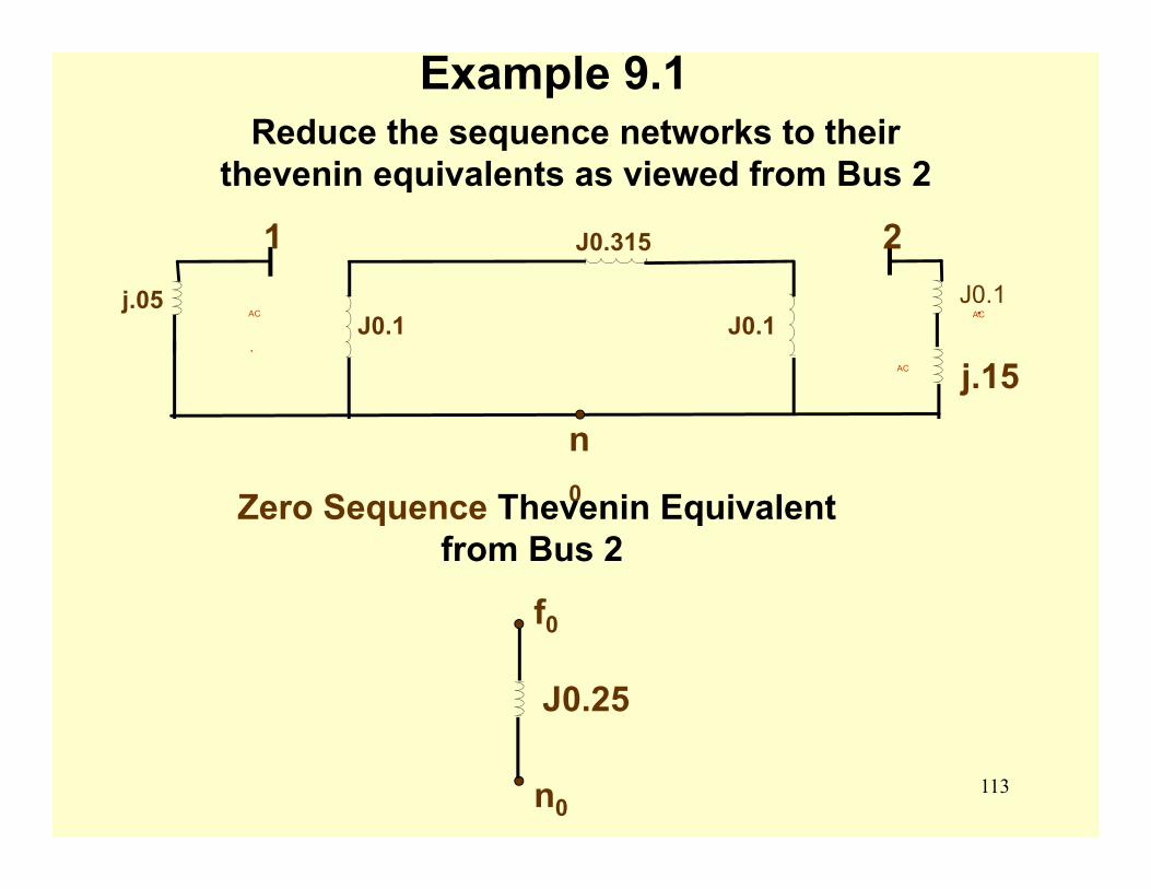
113
Example 9.1Reduce the sequence networks to their
thevenin equivalents as viewed from Bus 2
AC AC
.AC
j.05J0.1
J0.315
J0.1J0.1.
1 2
j.15
n0Zero Sequence Thevenin Equivalent
from Bus 2
f0
n0
J0.25
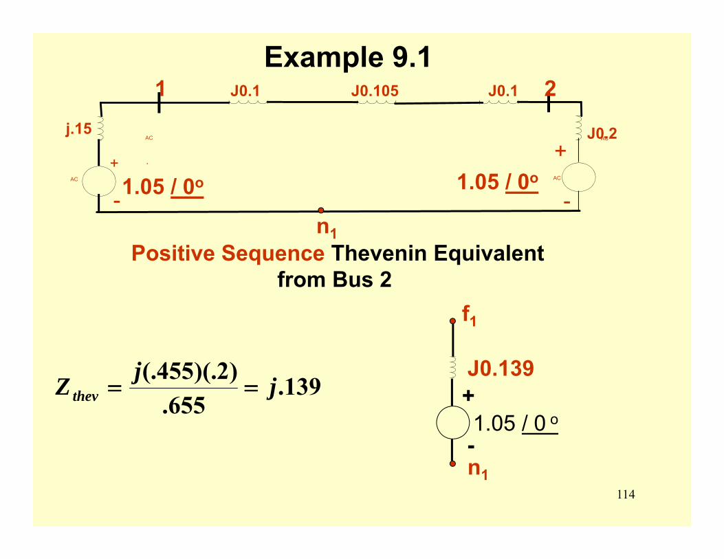
114
Example 9.1
AC AC
.
AC AC
j.15
-
+
J0.1 J0.105 J0.1
J0.2.
-
+
1 2
1.05 / 0o 1.05 / 0o
n1Positive Sequence Thevenin Equivalent
from Bus 2
139.655.
)2)(.455(. jjZthev ==
f1
n1
J0.139+
-1.05 / 0 o
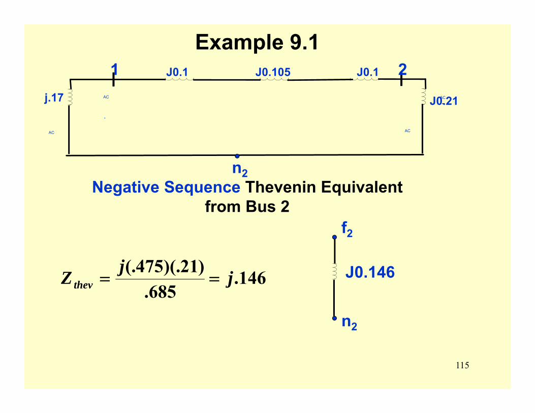
115
Example 9.1
Negative Sequence Thevenin Equivalent from Bus 2
146.685.
)21)(.475(. jjZthev ==
f2
n2
J0.146
AC AC
j.17
J0.1 J0.105 J0.1
J0.21.
1 2
n2
AC AC
.
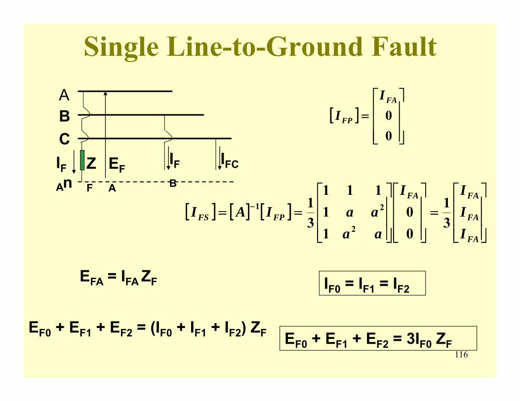
116
Single Line-to-Ground Fault
[ ]⎥⎥⎥
⎦
⎤
⎢⎢⎢
⎣
⎡=
00FA
FP
II
[ ] [ ] [ ]⎥⎥⎥
⎦
⎤
⎢⎢⎢
⎣
⎡=
⎥⎥⎥
⎦
⎤
⎢⎢⎢
⎣
⎡
⎥⎥⎥
⎦
⎤
⎢⎢⎢
⎣
⎡== −
FA
FA
FAFA
FPFS
IIII
aaaaIAI
31
00
11
111
31
2
21
IF0 = IF1 = IF2EFA = IFA ZF
EF0 + EF1 + EF2 = (IF0 + IF1 + IF2) ZF EF0 + EF1 + EF2 = 3IF0 ZF
ABCIFA
EF
A
IFB
IFC
nZF
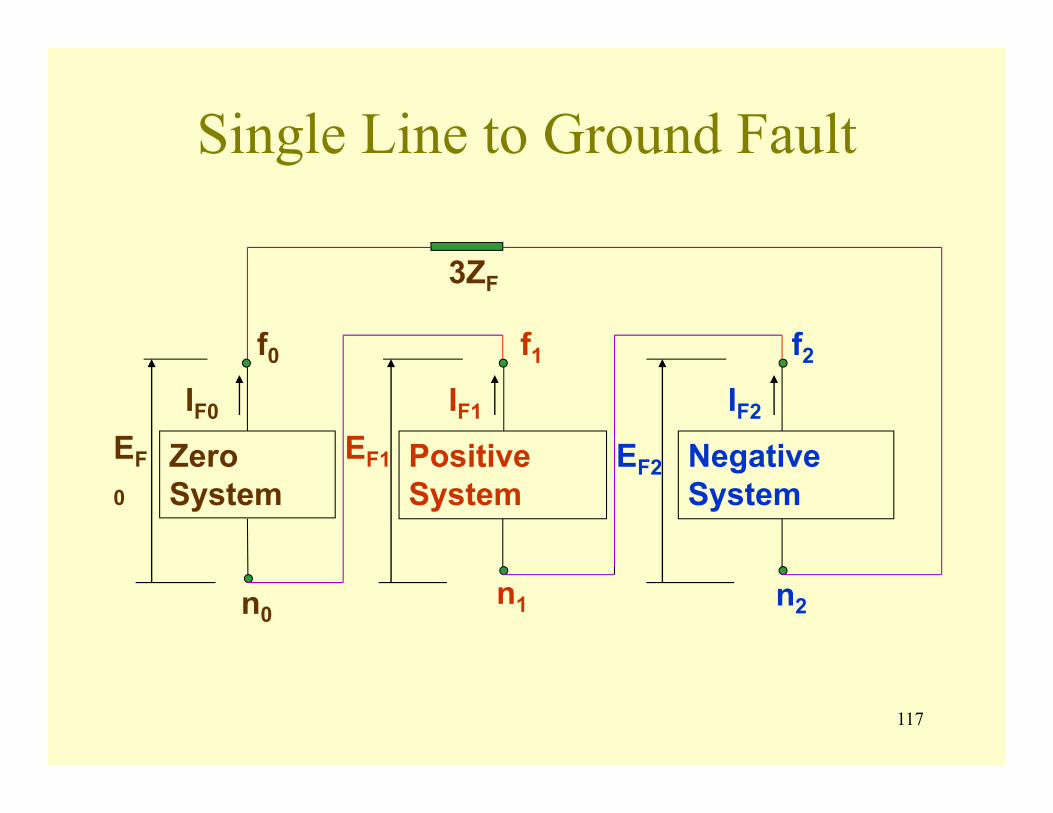
117
Single Line to Ground Fault
Zero System
Positive System
Negative System
f0 f1 f2
n0n1 n2
IF0 IF1 IF2
EF
0
EF1 EF2
3ZF
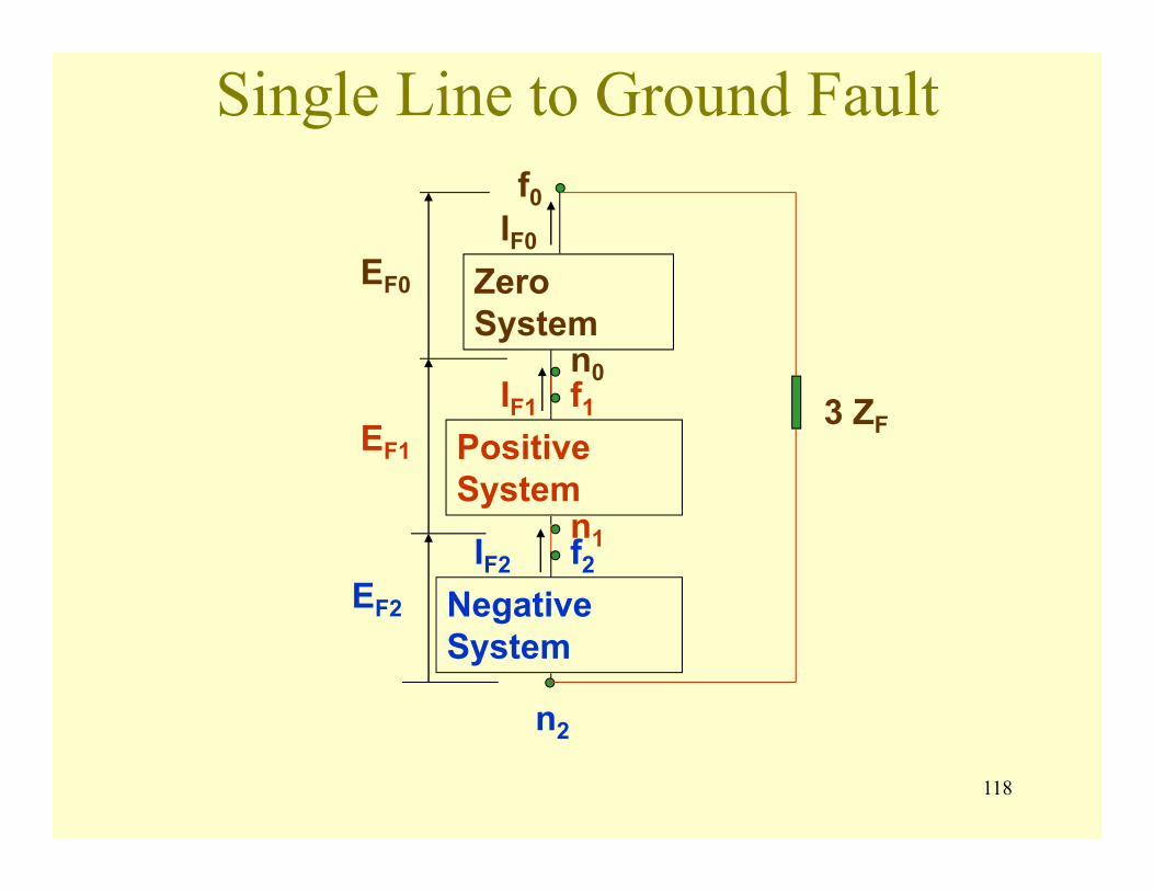
118
Single Line to Ground Fault
Zero System
Positive System
Negative System
f0
f1
f2
n0
n1
n2
IF0
IF1
IF2
EF0
EF1
EF2
3 ZF
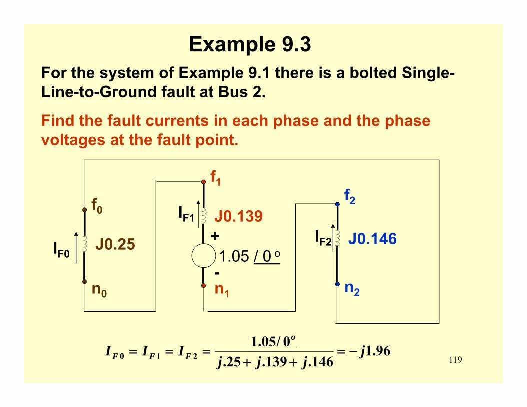
119
Example 9.3For the system of Example 9.1 there is a bolted Single-Line-to-Ground fault at Bus 2.
Find the fault currents in each phase and the phase voltages at the fault point.
f0
n0
J0.25
f1
n1
J0.139+
-1.05 / 0 o
f2
n2
J0.146IF0IF2
IF1
96.1146.139.25.
0/05.1210 j
jjjIII
o
FFF −=++
===
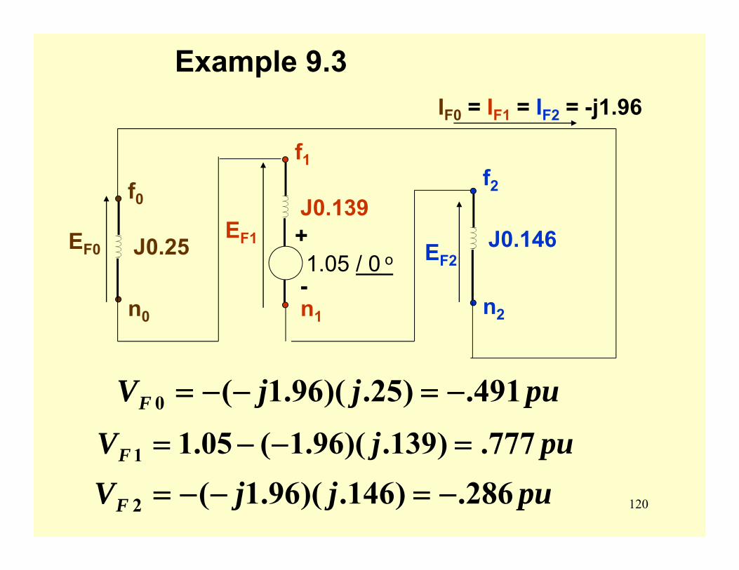
120
Example 9.3
f0
n0
J0.25
f1
n1
J0.139+
-1.05 / 0 o
f2
n2
J0.146
IF0 = IF1 = IF2 = -j1.96
EF0 EF2
EF1
pujjVF 491.)25.)(96.1(0 −=−−=
pujVF 777.)139.)(96.1(05.11 =−−=
pujjVF 286.)146.)(96.1(2 −=−−=
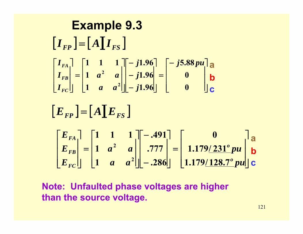
121
Example 9.3[ ] [ ][ ]FSFP IAI =
⎥⎥⎥
⎦
⎤
⎢⎢⎢
⎣
⎡−=
⎥⎥⎥
⎦
⎤
⎢⎢⎢
⎣
⎡
−−−
⎥⎥⎥
⎦
⎤
⎢⎢⎢
⎣
⎡=
⎥⎥⎥
⎦
⎤
⎢⎢⎢
⎣
⎡
0088.5
96.196.196.1
11
111
2
2
puj
jjj
aaaa
III
FC
FB
FA
[ ] [ ][ ]FSFP EAE =
⎥⎥⎥
⎦
⎤
⎢⎢⎢
⎣
⎡=
⎥⎥⎥
⎦
⎤
⎢⎢⎢
⎣
⎡
−
−
⎥⎥⎥
⎦
⎤
⎢⎢⎢
⎣
⎡=
⎥⎥⎥
⎦
⎤
⎢⎢⎢
⎣
⎡
pupu
aaaa
EEE
o
o
FC
FB
FA
7.128/179.1231/179.10
286.777.491.
11
111
2
2
Note: Unfaulted phase voltages are higher than the source voltage.
abc
abc
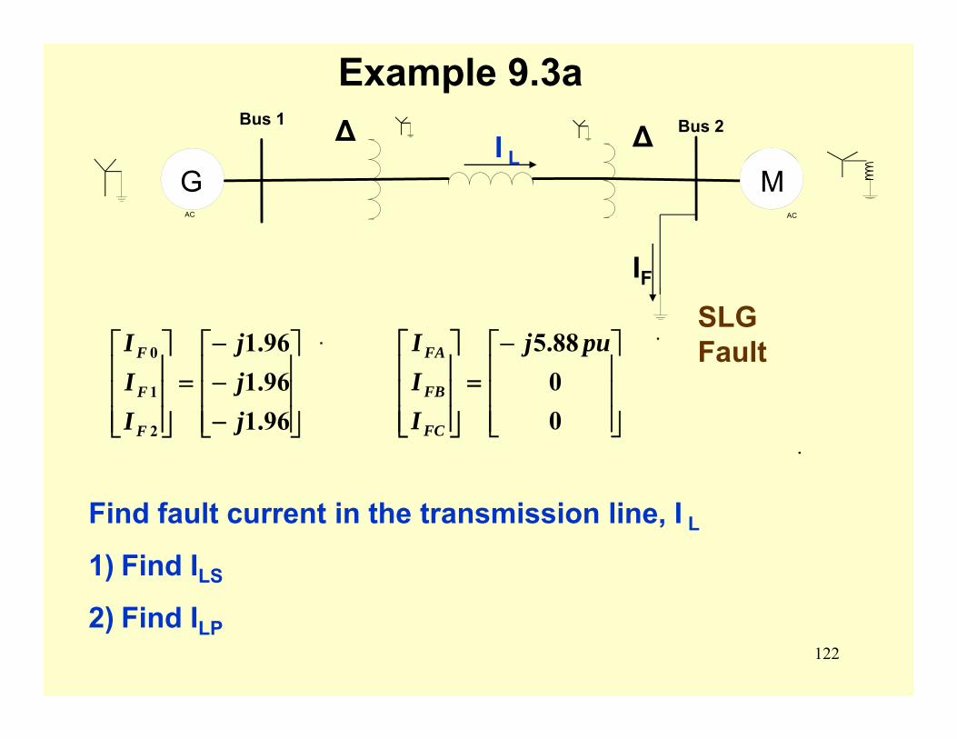
122
.
Example 9.3a
Find fault current in the transmission line, I L
1) Find ILS
2) Find ILP
⎥⎥⎥
⎦
⎤
⎢⎢⎢
⎣
⎡−=
⎥⎥⎥
⎦
⎤
⎢⎢⎢
⎣
⎡
0088.5 puj
III
FC
FB
FA
⎥⎥⎥
⎦
⎤
⎢⎢⎢
⎣
⎡
−−−
=⎥⎥⎥
⎦
⎤
⎢⎢⎢
⎣
⎡
96.196.196.1
2
1
0
jjj
III
F
F
F. .
AC
Bus 1
AC
Bus 2∆ ∆G M
SLG Fault
IF
I L
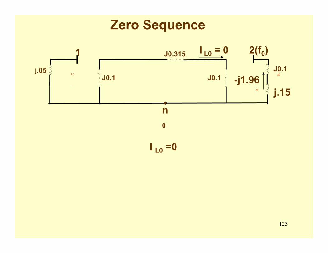
123
Zero Sequence
AC AC
.AC
j.05J0.1
J0.315
J0.1J0.1.
1 2(f0)
j.15
n0
-j1.96
I L0 = 0
I L0 =0
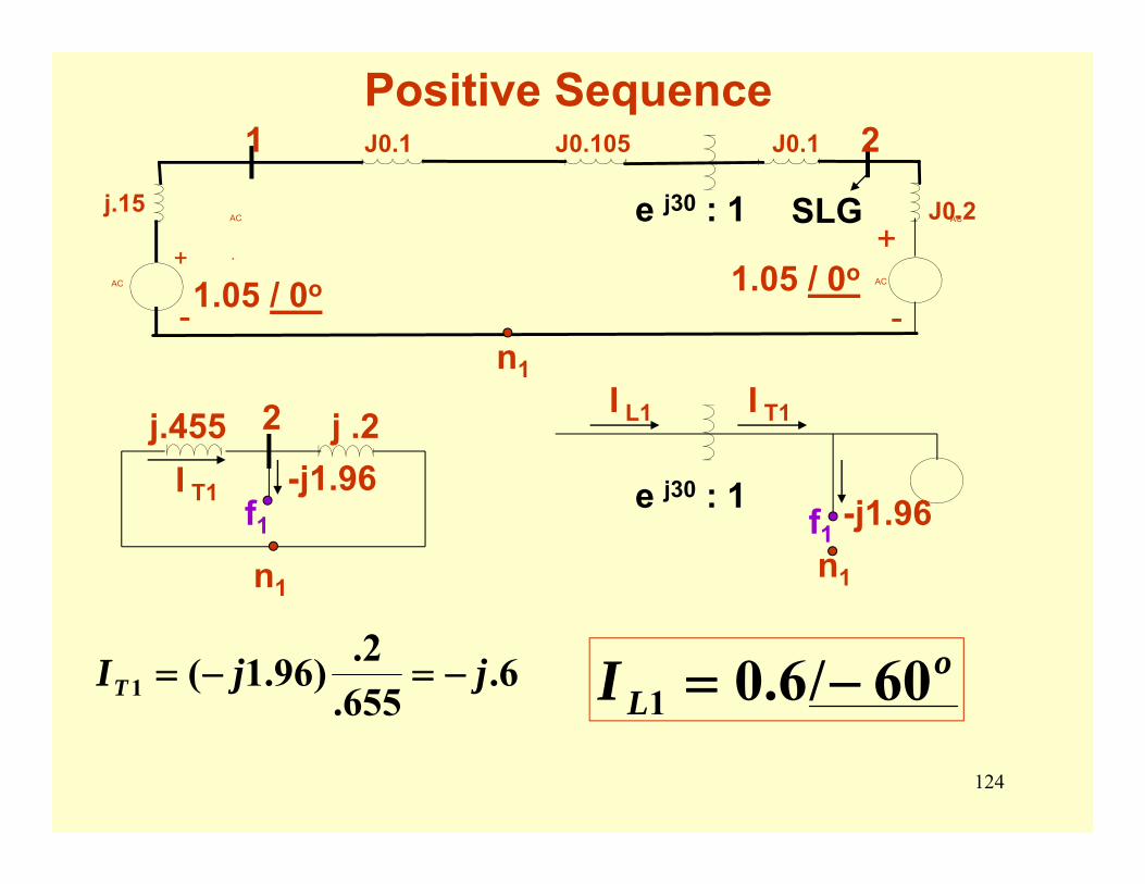
124
Positive Sequence
AC AC
.
AC AC
j.15
-
+
J0.1 J0.105 J0.1
J0.2.
-
+
1 2
1.05 / 0o 1.05 / 0o
n1
e j30 : 1 SLG
e j30 : 1
n1
-j1.96
I T1I L1
6.655.2.)96.1(1 jjIT −=−= o
LI 60/6.01 −=
n1
j.455 j .22
I T1 -j1.96f1 f1
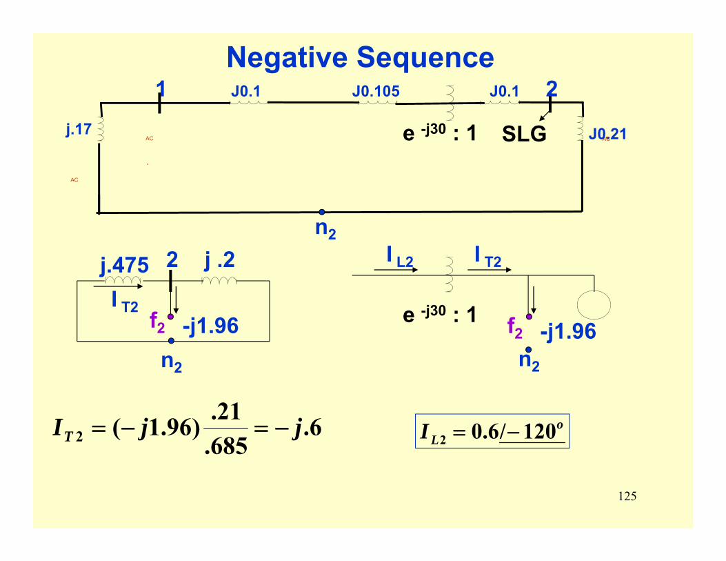
125
Negative Sequence
e -j30 : 1
n2
-j1.96
I T2I L2
n2
j.475 j .22
I T2-j1.96
6.685.21.)96.1(2 jjIT −=−= o
LI 120/6.02 −=
AC AC
.
AC
j.17
J0.1 J0.105 J0.1
J0.21.
1 2
n2
e -j30 : 1 SLG
f2 f2

126
Example 9.3a
[ ] [ ][ ]⎥⎥⎥
⎦
⎤
⎢⎢⎢
⎣
⎡−=
⎥⎥⎥
⎦
⎤
⎢⎢⎢
⎣
⎡
−−
⎥⎥⎥
⎦
⎤
⎢⎢⎢
⎣
⎡==
puj
puj
aaaaIAI
o
oPSPL
039.10039.1
120/6.60/6.
0
11
111
2
2
[ ]⎥⎥⎥
⎦
⎤
⎢⎢⎢
⎣
⎡
−−=
o
oLSI
120/6.60/6.
0 012
abc
. .
AC
Bus 1
AC
Bus 2∆ ∆G M
SLG Fault
IF
I L
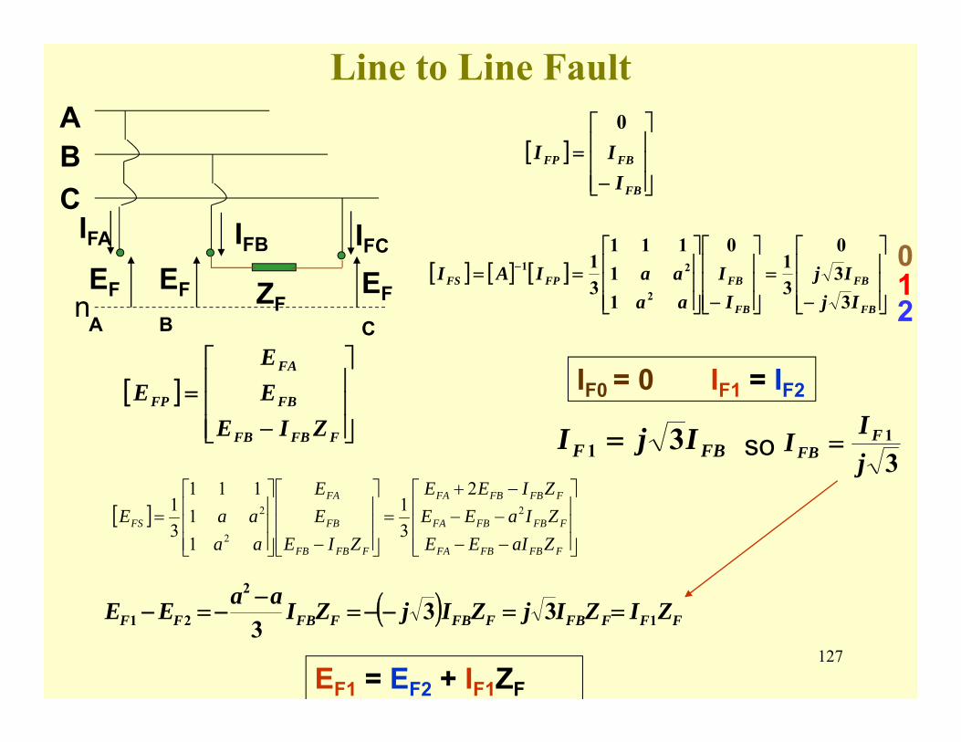
127
Line to Line Fault
[ ]⎥⎥⎥
⎦
⎤
⎢⎢⎢
⎣
⎡
−=
FB
FBFP
III0
[ ] [ ] [ ]⎥⎥⎥
⎦
⎤
⎢⎢⎢
⎣
⎡
−=
⎥⎥⎥
⎦
⎤
⎢⎢⎢
⎣
⎡
−⎥⎥⎥
⎦
⎤
⎢⎢⎢
⎣
⎡== −
FB
FB
FB
FBFPFS
IjIj
II
aaaaIAI
330
31
0
11
111
31
2
21
[ ]⎥⎥⎥
⎦
⎤
⎢⎢⎢
⎣
⎡
−=
FFBFB
FB
FA
FP
ZIEEE
E
n
ABC
IFA
EF
A
IFB IFC
EF
B
EF
CZF
IF0 = 0 IF1 = IF2
( ) FFFFBFFBFFBFF ZIZIjZIjZIaaEE 1
2
21 333
==−−=−
−=−
FBF IjI 31 = so 31
jII F
FB =
EF1 = EF2 + IF1ZF
012
[ ]⎥⎥⎥
⎦
⎤
⎢⎢⎢
⎣
⎡
−−−−−+
=⎥⎥⎥
⎦
⎤
⎢⎢⎢
⎣
⎡
−⎥⎥⎥
⎦
⎤
⎢⎢⎢
⎣
⎡=
FFBFBFA
FFBFBFA
FFBFBFA
FFBFB
FB
FA
FS
ZaIEEZIaEEZIEE
ZIEEE
aaaaE 2
2
2
2
31
11
111
31
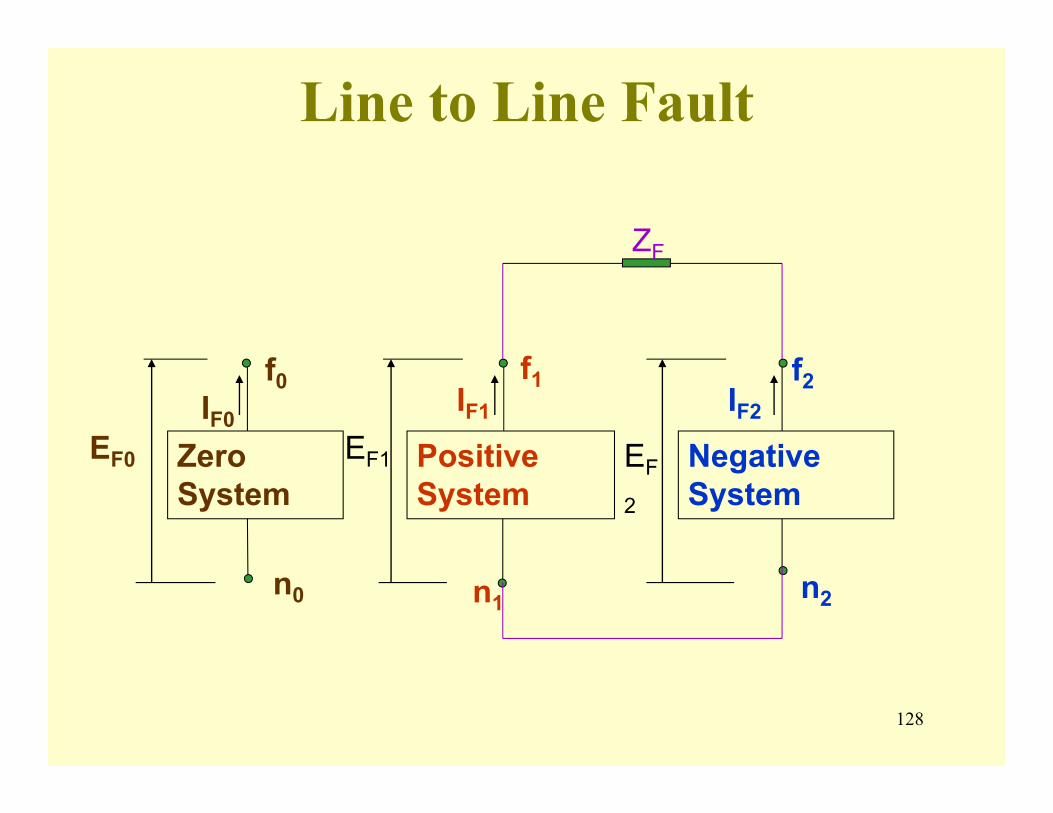
128
Line to Line Fault
Zero System
Positive System
Negative System
f0 f1 f2
n0 n1 n2
IF0IF1 IF2
EF0 EF1 EF
2
ZF
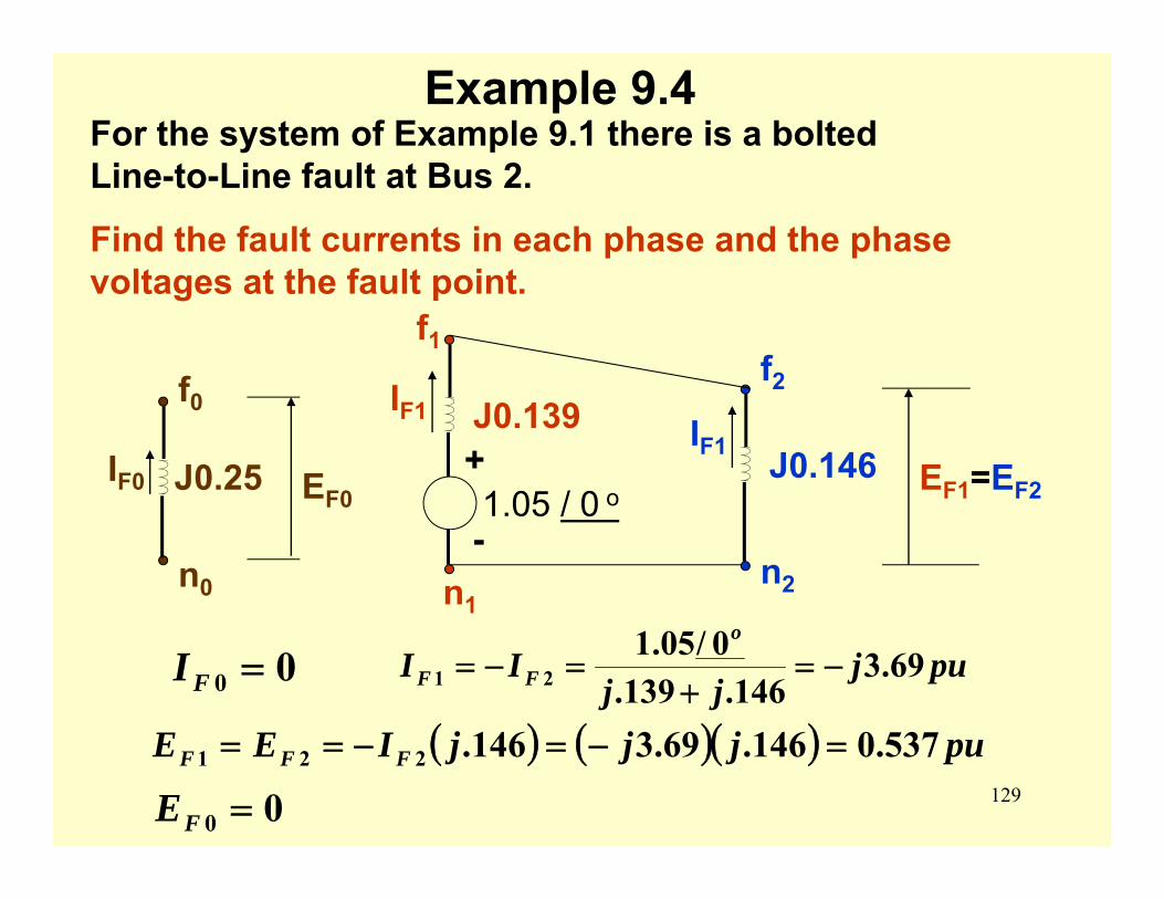
129
Example 9.4For the system of Example 9.1 there is a bolted Line-to-Line fault at Bus 2.
Find the fault currents in each phase and the phase voltages at the fault point.
f0
n0
J0.25
f1
n1
J0.139+
-1.05 / 0 o
f2
n2
J0.146
IF1IF1
IF0
pujjj
IIo
FF 69.3146.139.
0/05.121 −=
+=−=00 =FI
( ) ( )( ) pujjjIEE FFF 537.0146.69.3146.221 =−=−==
EF1=EF2EF0
00 =FE
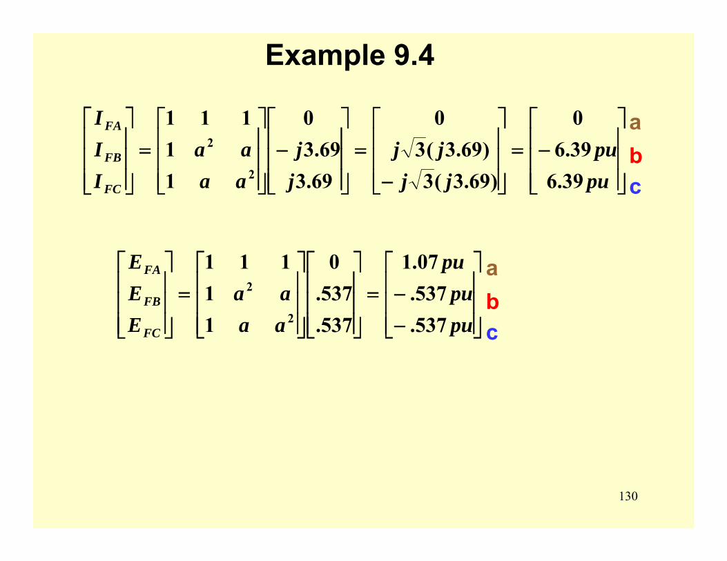
130
Example 9.4
⎥⎥⎥
⎦
⎤
⎢⎢⎢
⎣
⎡−=
⎥⎥⎥
⎦
⎤
⎢⎢⎢
⎣
⎡
−=
⎥⎥⎥
⎦
⎤
⎢⎢⎢
⎣
⎡−
⎥⎥⎥
⎦
⎤
⎢⎢⎢
⎣
⎡=
⎥⎥⎥
⎦
⎤
⎢⎢⎢
⎣
⎡
pupu
jjjj
jj
aaaa
III
FC
FB
FA
39.639.60
)69.3(3)69.3(3
0
69.369.3
0
11
111
2
2abc
⎥⎥⎥
⎦
⎤
⎢⎢⎢
⎣
⎡
−−=
⎥⎥⎥
⎦
⎤
⎢⎢⎢
⎣
⎡
⎥⎥⎥
⎦
⎤
⎢⎢⎢
⎣
⎡=
⎥⎥⎥
⎦
⎤
⎢⎢⎢
⎣
⎡
pupu
pu
aaaa
EEE
FC
FB
FA
537.537.07.1
537.537.0
11
111
2
2abc
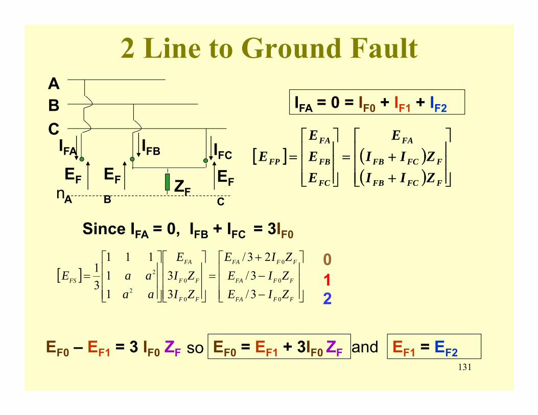
131
2 Line to Ground Fault
[ ] ( )( ) ⎥
⎥⎥
⎦
⎤
⎢⎢⎢
⎣
⎡
++=
⎥⎥⎥
⎦
⎤
⎢⎢⎢
⎣
⎡=
FFCFB
FFCFB
FA
FC
FB
FA
FP
ZIIZII
E
EEE
E
ABC
IFA
EF
A
IFB IFC
nEF
B
EF
CZF
IFA = 0 = IF0 + IF1 + IF2
Since IFA = 0, IFB + IFC = 3IF0
[ ]⎥⎥⎥
⎦
⎤
⎢⎢⎢
⎣
⎡
−−+
=⎥⎥⎥
⎦
⎤
⎢⎢⎢
⎣
⎡
⎥⎥⎥
⎦
⎤
⎢⎢⎢
⎣
⎡=
FFFA
FFFA
FFFA
FF
FF
FA
FS
ZIEZIEZIE
ZIZI
E
aaaaE
0
0
0
0
02
2
3/3/
23/
33
11
111
31
EF0 – EF1 = 3 IF0 ZF so EF0 = EF1 + 3IF0 ZF and EF1 = EF2
012
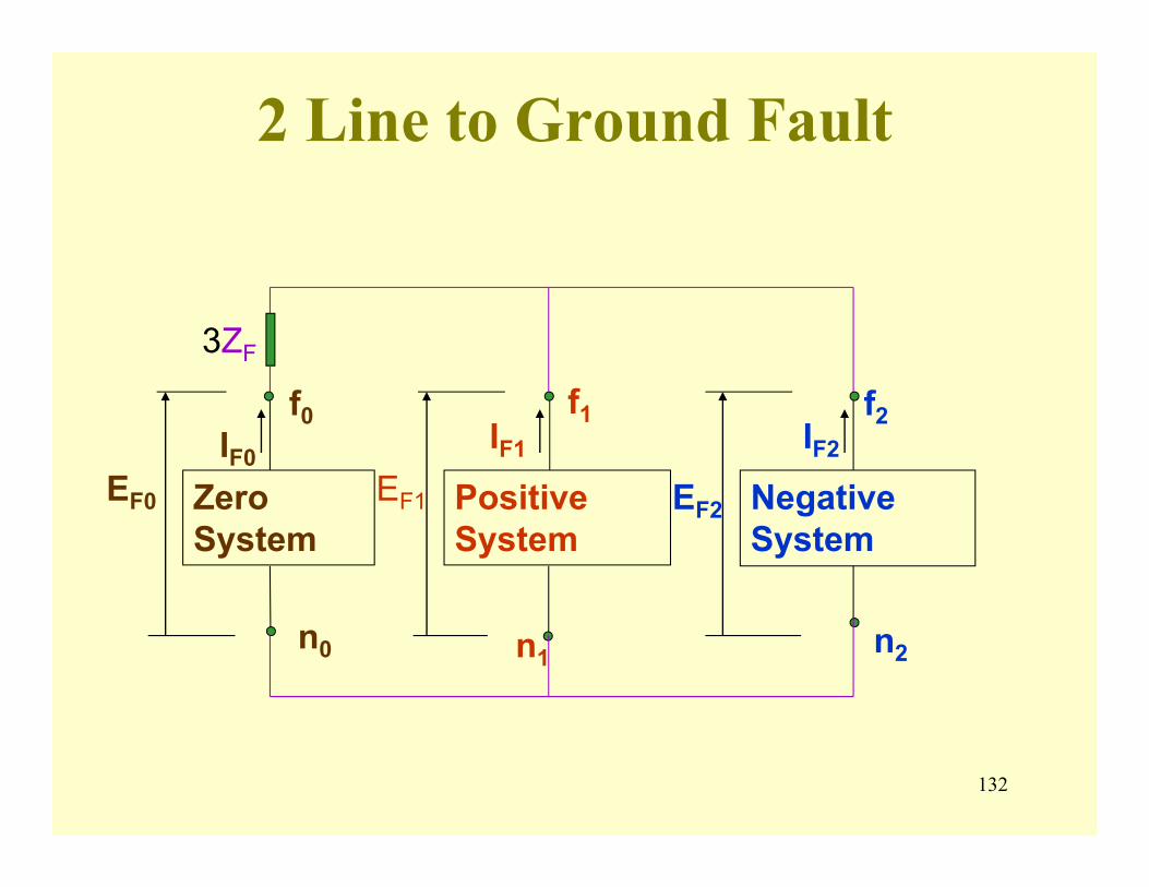
132
2 Line to Ground Fault
Zero System
Positive System
Negative System
f0 f1 f2
n0 n1 n2
IF0IF1 IF2
EF0 EF1 EF2
3ZF
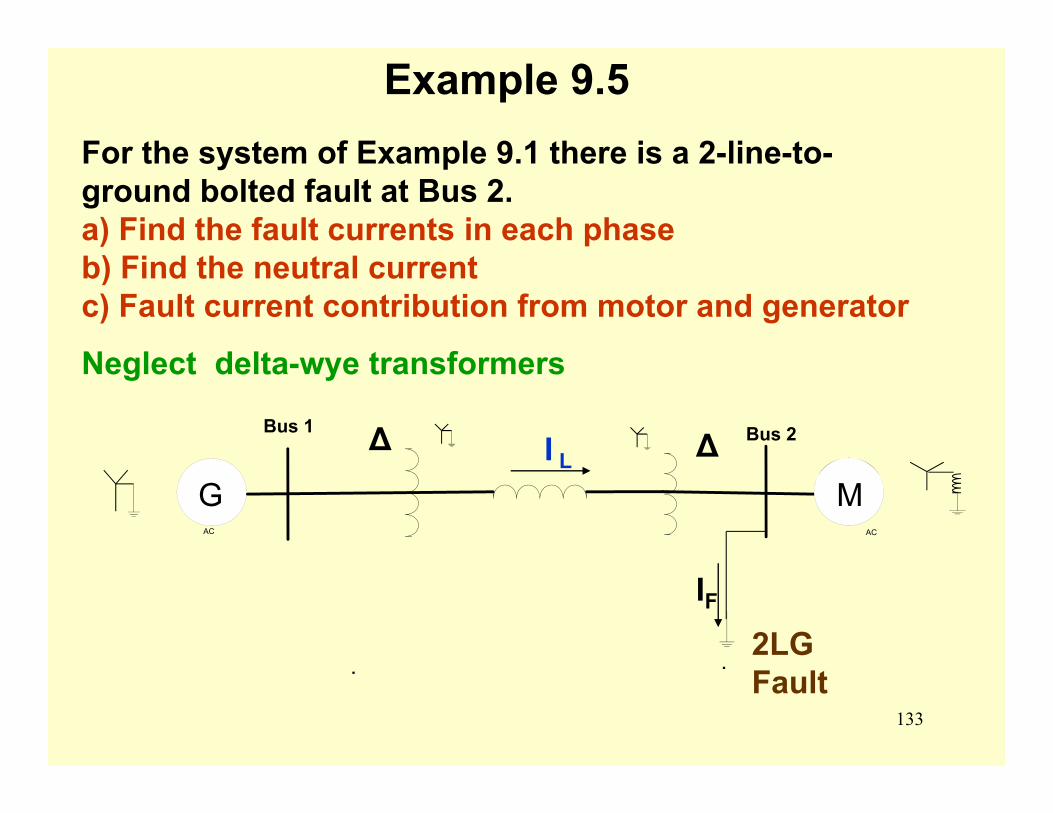
133
For the system of Example 9.1 there is a 2-line-to-ground bolted fault at Bus 2. a) Find the fault currents in each phase b) Find the neutral current c) Fault current contribution from motor and generator
Neglect delta-wye transformers
Example 9.5
. .
AC
Bus 1
AC
Bus 2∆ ∆G M
2LG Fault
IF
I L
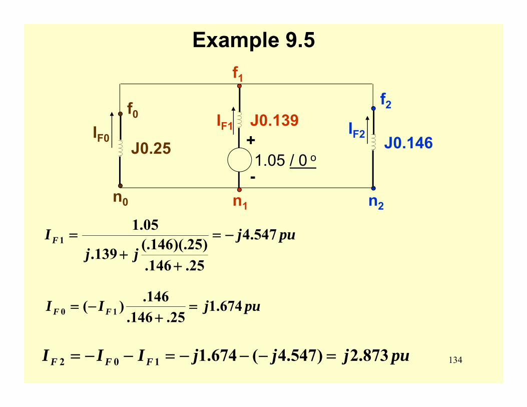
134
Example 9.5
f0
n0
J0.25
f1
n1
J0.139+
-1.05 / 0 o
f2
n2
J0.146IF0IF2
IF1
pujjj
IF 547.4
25.146.)25)(.146(.139.
05.11 −=
++
=
pujII FF 674.125.146.
146.)( 10 =+
−=
pujjjIII FFF 873.2)547.4(674.1102 =−−−=−−=
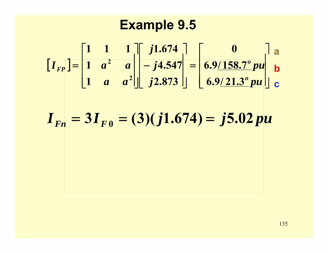
135
Example 9.5
This image cannot currently be displayed.[ ]⎥⎥⎥
⎦
⎤
⎢⎢⎢
⎣
⎡=
⎥⎥⎥
⎦
⎤
⎢⎢⎢
⎣
⎡−
⎥⎥⎥
⎦
⎤
⎢⎢⎢
⎣
⎡=
pupu
jj
j
aaaaI
o
oFP
3.21/9.67.158/9.6
0
873.2547.4
674.1
11
111
2
2abc
pujjII FFn 02.5)674.1)(3(3 0 ===
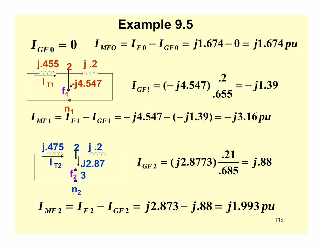
136
Example 9.5
n1
j.455 j .22I T1 -j4.547
n2
j.475 j .22I T2 J2.87
3
00 =GFI pujjIII GFFMFO 674.10674.100 =−=−=
39.1655.2.)547.4(! jjIGF −=−=
pujjjIII GFFMF 16.3)39.1(547.4111 −=−−−=−=
88.685.21.)8773.2(2 jjIGF ==
pujjjIII GFFMF 993.188.873.2222 =−=−=
f1
f2
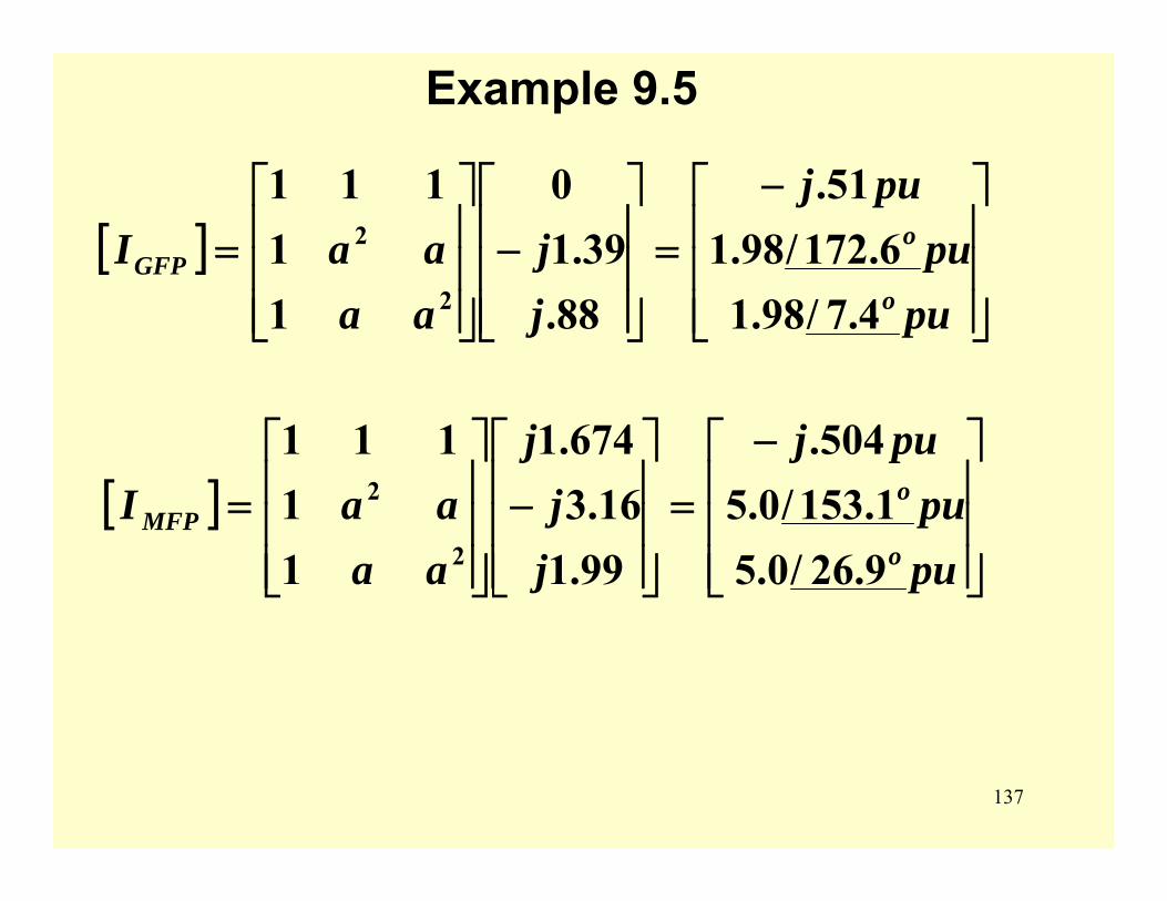
137
Example 9.5
[ ]⎥⎥⎥
⎦
⎤
⎢⎢⎢
⎣
⎡ −=
⎥⎥⎥
⎦
⎤
⎢⎢⎢
⎣
⎡−
⎥⎥⎥
⎦
⎤
⎢⎢⎢
⎣
⎡=
pupu
puj
jj
aaaaI
o
oGFP
4.7/98.16.172/98.1
51.
88.39.1
0
11
111
2
2
[ ]⎥⎥⎥
⎦
⎤
⎢⎢⎢
⎣
⎡ −=
⎥⎥⎥
⎦
⎤
⎢⎢⎢
⎣
⎡−
⎥⎥⎥
⎦
⎤
⎢⎢⎢
⎣
⎡=
pupu
puj
jj
j
aaaaI
o
oMFP
9.26/0.51.153/0.5
504.
99.116.3
674.1
11
111
2
2
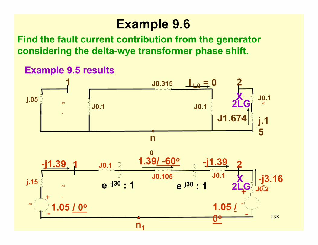
138
Example 9.5 results
AC AC
.AC
j.05J0.1
J0.315
J0.1J0.1.
1 2
j.15n
0
I L0 = 0
2LGJ1.674
X
AC AC
.
AC AC
j.15
-
+
J0.1J0.105 J0.1
J0.2.
-
+
1 2
1.05 / 0o 1.05 / 0o
n1
e -j30 : 1 2LGe j30 : 1-j3.16X
-j1.39
Find the fault current contribution from the generator considering the delta-wye transformer phase shift.
Example 9.6
1.39/ -60o-j1.39
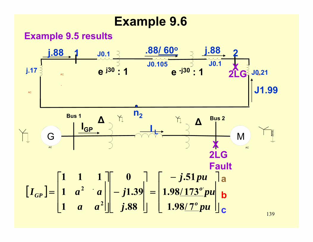
139
Example 9.6Example 9.5 results
J1.99
AC AC
.
AC
j.17
J0.1J0.105 J0.1
J0.21.
1 2
n2
e -j30 : 1 2LGe j30 : 1 X
j.88.88/ 60oj.88
. .
AC
Bus 1
AC
Bus 2∆ ∆G M
2LG Fault
I L
X
[ ]⎥⎥⎥
⎦
⎤
⎢⎢⎢
⎣
⎡ −=
⎥⎥⎥
⎦
⎤
⎢⎢⎢
⎣
⎡−
⎥⎥⎥
⎦
⎤
⎢⎢⎢
⎣
⎡=
pupu
puj
jj
aaaaI
o
oGP
7/98.1173/98.151.
88.39.1
0
11
111
2
2abc
IGP
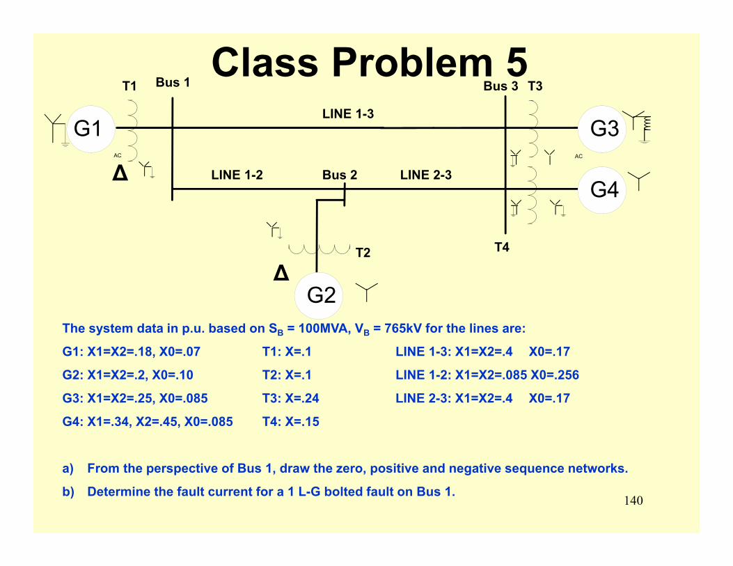
140
Class Problem 5
The system data in p.u. based on SB = 100MVA, VB = 765kV for the lines are:
G1: X1=X2=.18, X0=.07 T1: X=.1 LINE 1-3: X1=X2=.4 X0=.17
G2: X1=X2=.2, X0=.10 T2: X=.1 LINE 1-2: X1=X2=.085 X0=.256
G3: X1=X2=.25, X0=.085 T3: X=.24 LINE 2-3: X1=X2=.4 X0=.17
G4: X1=.34, X2=.45, X0=.085 T4: X=.15
a) From the perspective of Bus 1, draw the zero, positive and negative sequence networks.
b) Determine the fault current for a 1 L-G bolted fault on Bus 1.
AC
Bus 1
AC
Bus 3
∆
G1 G3
G4
G2
Bus 2
LINE 1-3
LINE 1-2 LINE 2-3∆
T1
T2
T3
T4
141
Modern Fault Analysis Methods
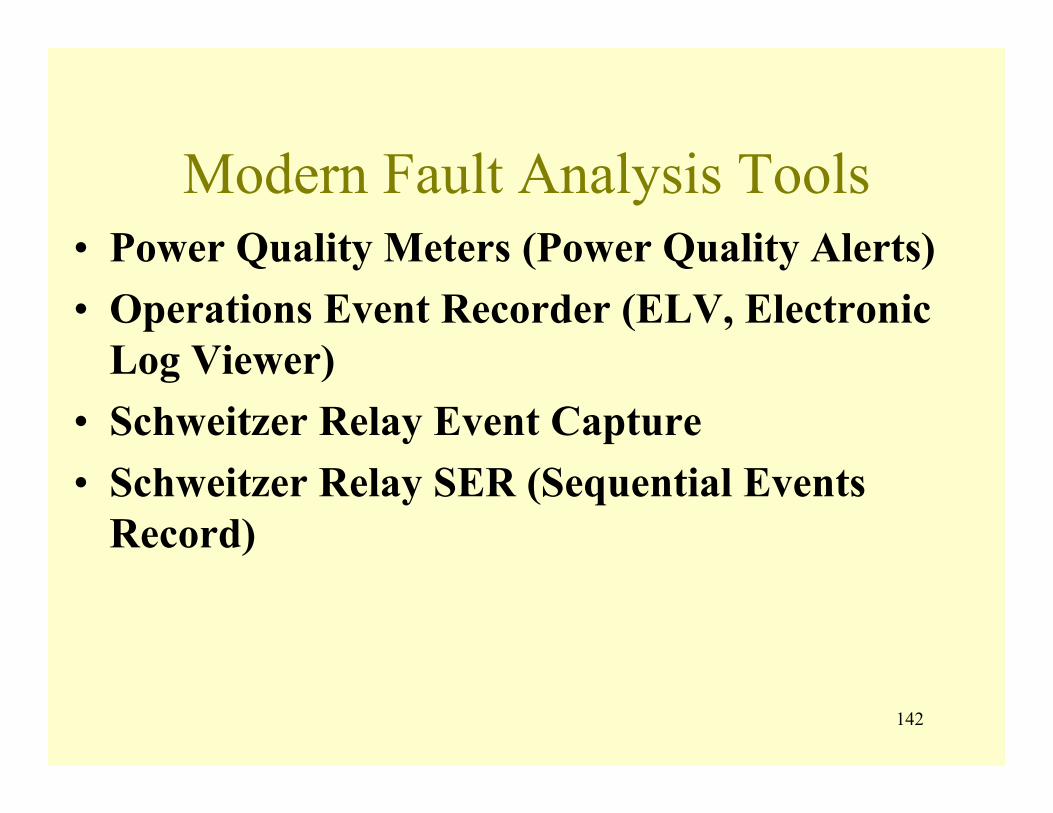
142
Modern Fault Analysis Tools• Power Quality Meters (Power Quality Alerts)• Operations Event Recorder (ELV, Electronic
Log Viewer)• Schweitzer Relay Event Capture• Schweitzer Relay SER (Sequential Events
Record)
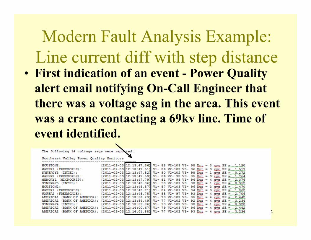
143
Modern Fault Analysis Example:Line current diff with step distance
• First indication of an event - Power Quality alert email notifying On-Call Engineer that there was a voltage sag in the area. This event was a crane contacting a 69kv line. Time of event identified.
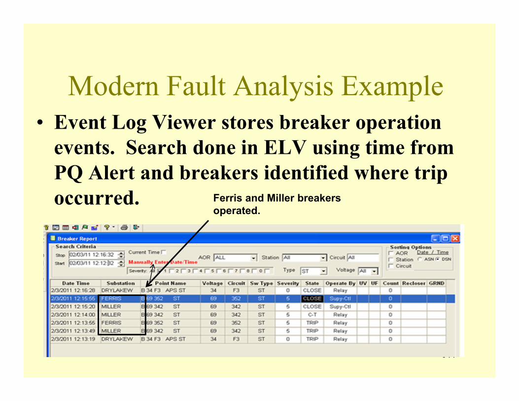
144
Modern Fault Analysis Example• Event Log Viewer stores breaker operation
events. Search done in ELV using time from PQ Alert and breakers identified where trip occurred. Ferris and Miller breakers
operated.
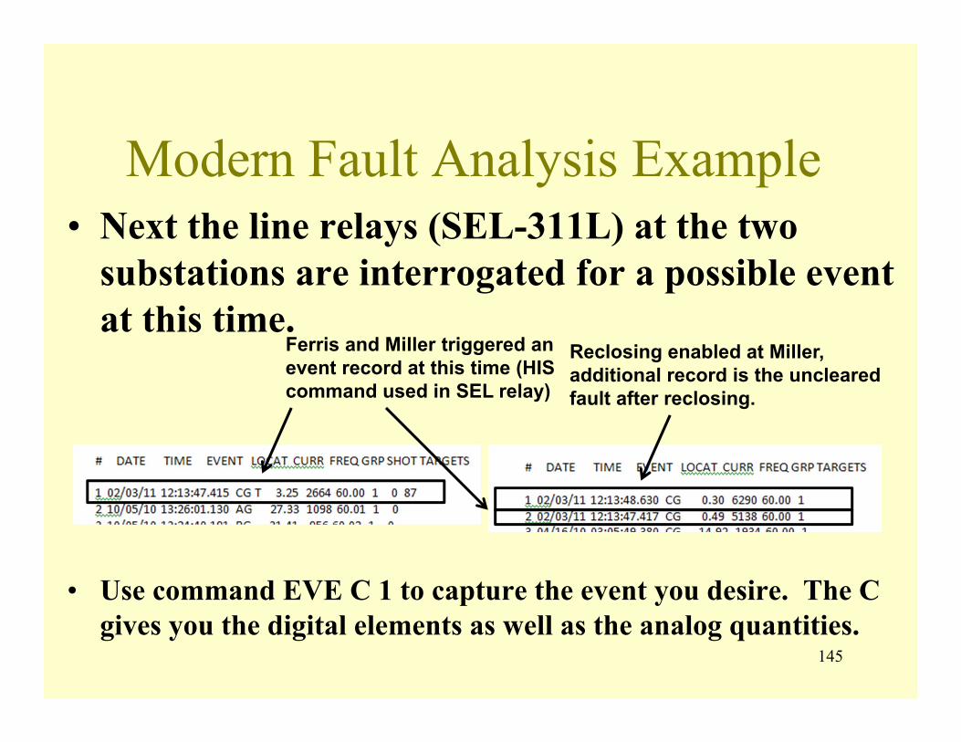
145
Modern Fault Analysis Example• Next the line relays (SEL-311L) at the two
substations are interrogated for a possible event at this time.
• Use command EVE C 1 to capture the event you desire. The C gives you the digital elements as well as the analog quantities.
Ferris and Miller triggered an event record at this time (HIS command used in SEL relay)
Reclosing enabled at Miller, additional record is the uncleared fault after reclosing.
146
Modern Fault Analysis Example• If the fault distance is not reasonable from the
relays, i.e. the fault distances from each end is longer then the line length, the fault magnitude can be modeled in Aspen to determine fault distance by running interim faults. This discrepancy in distance can result from tapped load or large infeed sources.
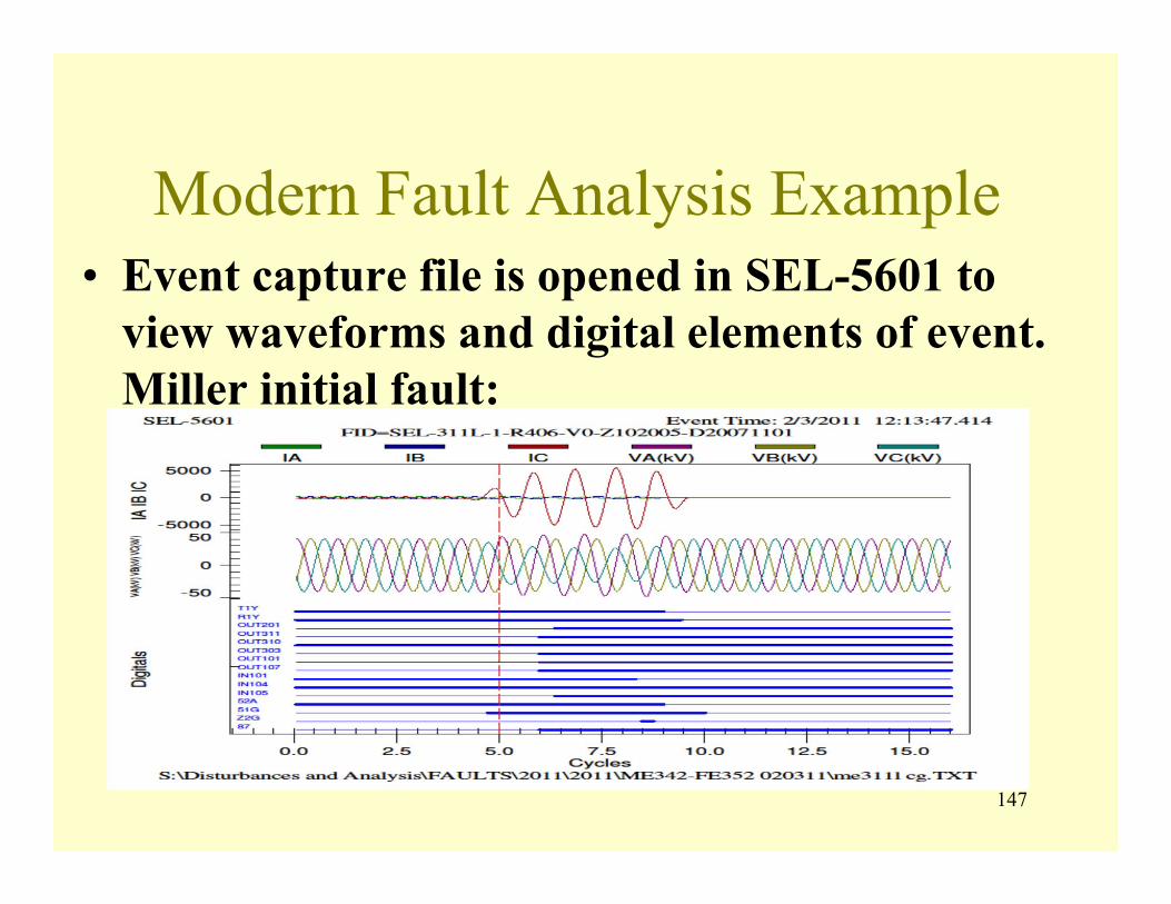
147
Modern Fault Analysis Example• Event capture file is opened in SEL-5601 to
view waveforms and digital elements of event. Miller initial fault:

148
Modern Fault Analysis Example• Event capture file is opened in SEL-5601 to
view waveforms and digital elements of event. Ferris initial fault: Unknown
source voltage
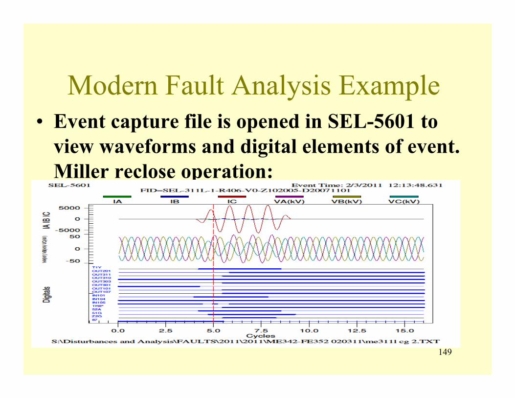
149
Modern Fault Analysis Example• Event capture file is opened in SEL-5601 to
view waveforms and digital elements of event. Miller reclose operation:
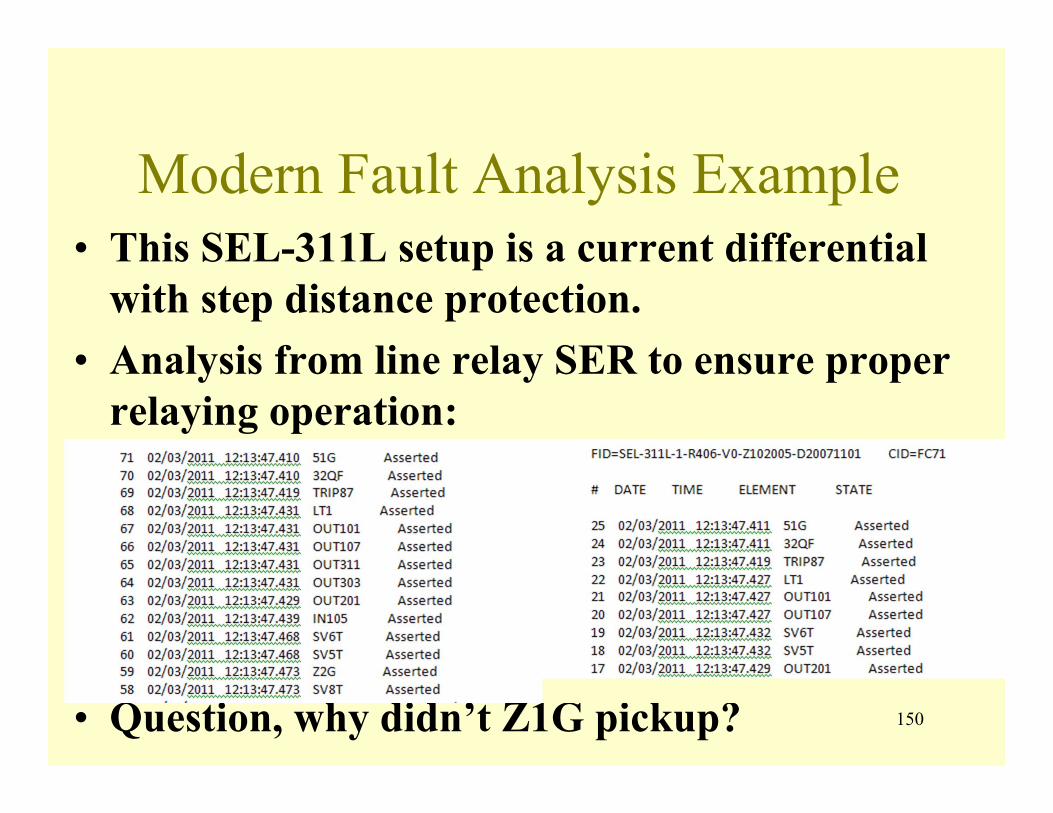
150
Modern Fault Analysis Example• This SEL-311L setup is a current differential
with step distance protection.• Analysis from line relay SER to ensure proper
relaying operation:
• Question, why didn’t Z1G pickup?

151
Questions