theory of plastic mechanism control of reinforced concrete
TRANSCRIPT

Science Arena Publications
Specialty Journal of Architecture and Construction Available online at www.sciarena.com
2020, Vol, 6 (2): 29-63
Theory of Plastic Mechanism Control of Reinforced Concrete Frames
Sajjad Najafi
Department of Civil Engineering, Faculty of Engineering, University of Lamerd Higher Education Cenrter, Lamerd, Iran.
Abstract: In this paper new advances for designing moment resisting concrete frames, failing in a global mode (TPMC: Theory of Plastic Mechanism Control), are presented. The TPMC theory has been developed in the nineties with reference to moment-resisting frames (MRFs) and progressively extended to several steel structural typologies commonly adopted as seismic-resistant structural systems. The proposed procedure is based on the application of the kinematic theorem of the plastic collapse through the evaluation of the sum of the plastic moments of the columns required, at each storey, to prevent undesired failure modes such as soft-storey mechanism. The second-order effects, due to vertical loads, can play an important role in the seismic design of rein-forced concrete (RC) frames. For this reason, they can be taken into account in the proposed approach through the equilibrium of the considered collapse mechanism. Significant improvements proposed by this approach include, among others, the possibility to account for different amount of reinforcement, not only at the top and bottom of the beam section, but also at the beam ends (left and right). A practical application of the TPMC process for the design of a multi-storey RC frame is presented with push-over and non-linear dynamic analyses that investigate the actual collapse mechanism of the designed structure. All the obtained results confirm the capability of the design procedure to achieve a collapse mechanism of global type. Keywords: Global mechanism, Concrete moment resisting frames, Plastic collapse theory
INTRODUCTION
Nowadays, the primary purpose of the structural design con-sists in avoiding a collapse mechanism characterized by minimum energy dissipation capacity of the structure, assuring instead the development of a mechanism of global type. In particular, such kind of mechanism is achieved by the development of plastic hinges at all the beam ends and at the base of the first storey columns. For moment resisting frames, the maximum number of plastic hinges is obtained when two plastic hinges develop in each bay at the beam ends. However, under particular loading conditions, plastic hinges can develop also at the bay mid span. In a collapse mechanism of global type, the energy dissipation capacity and global ductility supply are maximized because all the dissipative zones are involved in the corresponding pattern of yielding while all the other structural parts remain elastic. In the design of structures, it is clearly important to identify both dissipative and non-dissipative zones. The first ones are designed according to the internal actions generated by the seismic forces provided by the codes; the second ones are designed on the basis of the maxi-mum internal actions transmitted by the dissipative zones. In a seismic resistant concrete frame, beams are identified as

Spec. J. Archit. Constr, 2020, Vol, 6 (2): 29-63
30
dissipative zones while columns are identified as non-dissipative zones. These are the basic principles of capacity design approach, independently of the structural scheme and the building materials (Lee, 1996; Paulay, 1977; Paulay, 1980). In order to avoid undesired collapse mechanisms a hierarchy criterion, reported in all the modern seismic codes, suggests that at any structural joint, the sum of the flexural strength of the columns is greater than the sum of the flexural strength of the beams (EN, 1998; New Zealand Standard code of practice for the design of concrete structures, 1982). Generally, the beam–column hierarchy criterion, being based on simple joint equilibrium, is only able to prevent ‘‘soft-storey” mechanisms, but it does not assure the development of a collapse mechanism of global type (Heidari and Gharehbaghi, 2015; Godínez-Domínguez and Tena-Colunga, 2010; Bai and Ou, 2015; Leelataviwat et al., 2002; Hwang et al., 2010; Verderame et al., 2011). In addition, several research are devote in recent years to the understand of seismic collapse mode of RC frames, the induced loss and the retrofitting technics to be adopted in order to obtain a better and more dissipative collapse mechanism both in case of new structures (Hejazi et al., 2014; Hejazi et al., 2009; Oviedo et al., 2010; Han et al., 2010; Hejazi et al, 2011) and in case of existing structures (Mahrenholtz et al., 2015; D’Aniello et al., 2006; Della Corte et al., 2015; Mistakidis et al., 2007; Mazzolani et al., 2009). For this reason, an alternative design procedure, based on the kinematic theorem of plastic collapse and on a second order plastic analysis (i.e. the concept of mechanism equilibrium curve) has been presented in 1997 (Mazzolani and Piluso, 1997) for steel moment resisting frames and recently improved (Montuori et al., 2015). Based on the ‘‘Theory of Plastic Mechanism Control” (TPMC), for any given structural typology, the design requirement to pre-vent undesired collapse mechanisms imposes that the mechanism equilibrium curve of the global mechanism is located below those of all the other undesired mechanisms up to a displacement level compatible with the local ductility supply of dissipative zones. This design approach was successively extended to different steel structural typologies such as MRFs (Moment Resisting Frames) equipped with friction dampers (Piluso et al., 2014), EBFs (Eccentrically Braced Frames) (Montuori et al., 2014), dissipative truss-moment frames (Longo et al., 2012) and MRF–CBF (Concentrically Braced Frames) dual systems (Longo et al., 2014; Longo et al., 2016). So, it can be concluded that structures in high seismicity zones are normally designed in order to avoid the yielding of columns because the desired goal is always the development of a global mechanism. The TPMC is here developed for the RC frames removing the limitation of identical reinforcement at the beam ends (Montuori and Muscati, 2015). The simplicity of the proposed method is also emphasized by means of a case study. Static and inelastic dynamic analyses validate the occurrence of the desired collapse mechanism typology, i.e. a col-lapse mechanism of global type.
Theory of plastic mechanism control
In general, three main collapse mechanism typologies can be recognized for a frame structure: these mechanisms, depicted in Fig. 1 as type 1, 2 and 3, are to be considered undesired because they do not involve all the dissipative zones. Type-1 mechanism starts from the first storey level and involves an im-th number of storeys with plastic hinges developed at the beam ends of the storeys involved, at the base of the first storey columns and at the top of the im-th storey columns. Type-2 mechanism starts at the top of the structure and involves an im-th number of storeys. All the beam ends and the involved column bases develop plastic hinges. The global mechanism, representing the design goal, is a particular case of type-2 mechanism when involving all the storeys. Type-3 mechanism involves only one storey with plastic hinges developed at the base and top of the columns. It can be considered the worst mechanism because it involves only column sections which are less dissipative than the beam sections. TPMC allows to design a structure that will exhibit a global mechanism, i.e. assuring that plastic hinges develop only

Spec. J. Archit. Constr, 2020, Vol, 6 (2): 29-63
31
at beam ends while all the columns remain in the elastic range with the only exception of the first storey column base. In order to apply the TPMC it is of paramount importance the introduction of the concept of linearized mechanism equilibrium curve for each considered mechanism. The mathematical expression of this curve can be written as:
0 = − (1)
Fig. 1. Collapse mechanism typologies for a 2D frame structure.
where a0 is the kinematically admissible multiplier of horizontal forces, c is the slope of the curve and d is the top-sway displacement. Both parameters can be derived, according to rigid-plastic theory, using the virtual work principle. Within the framework of a kinematic approach, for any given collapse mechanism, the mechanism equilibrium curve can be easily obtained by equaling the external work to the internal work. In addition, in order to account for second-order effects, the external second-order work due to the vertical loads is also considered. The procedure presented hereafter allows to overcome all the limitations of the previous formulation (Montuori and Muscati, 2015) and to consider a generic frame with non-symmetric reinforcement distribution (different top and bottom and left and right ends) for the beams reinforcement. Obviously it means that we have to consider both directions of the earthquake because the sum of plastic design resistance of beams is different for two directions (Left to Right and Right to Left). For clarity the notation reported in Table 1 was adopted. It is important to note that the quantities involved in the eval-uation of internal work, for each considered mechanism, depend on the direction of the seismic input. In fact, due to the non-symmetric configuration of reinforcement (top and bottom at each end of the beam) four different plastic moments can be defined for each beam. When a collapse mechanism involves the generic beam, two of them are to be used for earthquake direction from left to right (LR) and, the other two, are to be used for earthquake from right to left (RL) (Fig. 2). In Fig. 2 the sign ‘‘+” is used to indicate that the bending moment produces tension in lower fibers of the beam section and compression in the upper fibers, while the sign ‘‘ ” is used to indicate the opposite

Spec. J. Archit. Constr, 2020, Vol, 6 (2): 29-63
32
case. For the evaluation of the kinematically admissible multiplier of horizontal forces, corresponding to the generic mechanism, it is easy to recognize that, in case of global type mechanism, for a plastic hinge rotation dθ of the first storey columns, the internal work can be expressed, for earthquake from Left to Right (LR) as:
Table 1. Notation.
nc Number of columns e Index of beam ends (e- L- left end. e - R- right
end)
nb Number of bays Mc;im Plastic moment of the fth column at i*-th
storey
ns Number of storeys Mc;im = Σm=1n Mc;im Sum of column plastic moments at 1.-th storey
𝐢𝐦 Index of mechanism Mv = ΣK=1n Vkhk Sum of products between the vertical loads acting on fcth storey and the corresponding
height
Ho Sum of the interstorey heights of the
storeys involved by the generic mechanism
Mf = ΣK=1n Fkhk Overturning moment of horizontal forces
hk Height of the Jrth storey (with It-1.2
n.) F=H^Fk Sum of the horizontal forces 𝐟𝐤
Horizontal force applied to the fcth storey
M𝐛𝐉𝐤 Plastic design resistance of beam at jth bay of the fcth storey
vk Sum of all the vertical loads acting at
kth storey Mb.R.ⅆ.e Sum of the plastic design resistances of beam
ends (for e end) in the global mechanism
, , ,1 . , . ,R
1 1 1 1 1
,1 .Rd, .Rd,R
c s b s bn n n n n
i LR c i b jk L b jk
i k j k j
c b L b
W M M M d
M M M d
+ +
= = = = =
− +
= + +
= + +
(2)
For earthquake from Right to Left (RL):
, , ,1 . , . ,R
1 1 1 1 1
,1 .Rd, .Rd,R
c s b s bn n n n n
i RL c i b jk L b jk
i k j k j
c b L b
W M M M d
M M M d
− −
= = = = =
+ −
= + +
= + +
(3)
The external work due to horizontal forces, is:
1
sn
e k k F
k
W F h d M d =
= = (4)
This value is the same for both LR and RL seismic input direction. The application of the virtual work principle provides the kinematically admissible multiplier that, for LR earthquake, can be written as:
,1 .Rd, .Rd,R( )
0,
c b L bg
LR
F
M M M
M
+ − + + = (5)

Spec. J. Archit. Constr, 2020, Vol, 6 (2): 29-63
33
and for RL earthquake:
,1 .Rd, .Rd,R( )
0,
c b L bg
LR
F
M M M
M
− + + + = (6)
In order to compute the slope of the mechanism equilibrium curve, it is necessary to evaluate the second-order work due to vertical loads. It can be observed in Fig. 3 that the horizontal displacement of the kth storey uk=rksinθ, where rk is the distance of the kth storey from the center of rotation C and h the angle of rotation. The top sway displacement is given by δ=H0sinθ, where Ho is the sum of the heights of the storeys involved by the generic mechanism. In case of global type mechanism, as shown in Fig. 1, all the storeys participate to the collapse mechanism, so that H0=hns. The relationship between vertical and horizontal virtual displacements at storey k is given by (Fig. 3):
Fig. 2. Plastic moment to be considered for LR and RL earthquake direction for each beam involved
in the considered collapse mechanism.
Fig. 3. Second order vertical displacements.
0
tan sink k k kd du du duH
= = (7)
Spec. J. Archit. Constr, 2020, Vol, 6 (2): 29-63
34
It shows that, as the ratio dνk/duk does not depend on the considered storey, vertical and horizontal virtual displacement vectors have the same shape i.e. they differ only for a constant value given by d=Ho. The virtual horizontal displacements are given by:
0
tan sink k k kd du du duH
= = (8)
By substituting Eq. (8) in Eq. (7), the virtual vertical displacements can be obtained as:
0
k kd r dH
= (9)
and, therefore, they have the same shape of the horizontal ones. Based on these geometrical conditions, the second-order work due to vertical loads for the global mechanism is calculated as:
1 0 0
sn
v k k V
k
W V h d M dH H
=
= = (10)
This quantity, like the external work We of Eq. (4), is not dependent on the seismic input direction. The virtual work principle can be written, for LR earthquake, as:
,i LR e vW W W= + (11)
By substituting Eqs. (2), (4) and (10) in Eq. (11) the following relation can be obtained:
,1 .Rd, .Rd,R
0
c b L b F VM M M d M d M dH
+ − + + = + (12)
Similarly for RL earthquake due to the virtual work principle:
,i RL e vW W W= + (13)
and by substituting Eqs. (3), (4) and (10) in Eq. (13):
,1 .Rd, .Rd,R
0
c b L b F VM M M d M d M dH
− + + + = + (14)
By simple manipulations the form of the linearized mechanism equilibrium curve expressed by Eq. (1) can be obtained for LR earthquake:
,1 .Rd, .Rd,R( ) ( ) ( ) 00,
1V
c b L bg g g
LR LR
F F
MM M M H
M M
+ −+ += − = − (15)

Spec. J. Archit. Constr, 2020, Vol, 6 (2): 29-63
35
While for earthquake, RL is :
,1 ,Rd, ,Rd,R( ) ( ) ( ) 00,RL
1V
c b L bg g g
RL
F F
MM M M H
M M
− ++ += − = − (16)
The slope of the mechanism equilibrium curve γ is given by:
( ) 0
11
s
VVng
F F
MMhH
M M = = (17)
This parameter is not dependent on the seismic input direction. It must be underline that the linearization of the equilibrium curve is due to the small displacement theory adopted in Eq. (8). In fact, due to this assumption, the second-order work due to vertical loads is linear as well as the mechanism equilibrium curve. For each considered mechanism of Fig. 1 an equilibrium curve can be obtained. In particular, for the im-th storey (im=1,2,…,ns); nsÞ of the t-th typology (t=1,2,3)،the application of the kinematic theorem of
plastic collapse provides, for LR earthquake:
( ) ( ) ( )
, 0, , t=1,2,3 i 1,2,...,t t t
im LR im LR im m sn = − = (18)
and for RL earthquake:
( ) ( ) ( )
,RL 0, , t=1,2,3 i 1,2,...,t t t
im im RL im m sn = − = (19)
where 𝛼0,𝑖𝑚(𝑡) and 𝛾0,𝑖𝑚(𝑡) represent, respectively, the kinematically admissible multiplier and the slope of
mechanism equilibrium curve of the im-th storey of the t-th typology. In the proposed method the beam section properties are assumed to be known quantities because they are designed to resist vertical loads. As a consequence, the design unknowns are the geometry and reinforcement of the column cross-sections. They could be determined by imposing that the kinematically admissible multiplier of the global mechanism is the minimum among all multipliers for all other mechanisms (Fig. 1). This design requirement is able to assure the desired col-lapse mechanism only in case of rigid-plastic behavior, while actual structures are characterized by elastic displacements before the development of a plastic mechanism. Due to these elastic displacements, second-order effects of vertical loads cannot be neglected. These effects can be taken into account when the equilibrium curve corresponding to the global mechanism lies below those of the other mechanisms (i.e. the upper bound theorem of plastic design is to be satisfied for each value of the displacements δ (Fig. 4)). However, the fulfilment of this requirement is necessary only up to a selected ultimate displacement δu which has to be compatible with the ductility capacity of structural members. It must be noted the value of du is related to the available capacity of members involved in the global mechanism, i.e. beam ends and base columns. It is well known that the value of the available rotational ductility depends on several factors such as: the amount of confinement steel (stirrups), the concrete and steel grade, the area of longitudinal bars and the value of axial load. So when a rotational capacity is assumed in the design, then that ductility must be pro-vided by the design of the structural detail of the section. To

Spec. J. Archit. Constr, 2020, Vol, 6 (2): 29-63
36
better clarify this aspect, in the two study cases presented in the following, two different values of rotational capacity have been assumed. This condition depicted in Fig. 4, for LR earthquake, can be expressed as:
( ) ( ) ( ) ( ) ( ) ( )
0, 0, , ,
g g g t t t
LR LR u im LR im u im LR = − − = (20)
Figure 4. Design Condition
And for earthquake RL:
( ) ( ) ( ) ( ) ( ) ( )
0,RL 0, , ,RL
g g g t t t
RL u im RL im u im = − − = (21)
with im1,2,3,…,ns و t=1,2,3. For a structure with ns storeys, there are 6ns design conditions to be satisfied. The kinematically admissible multiplier of the seismic horizontal forces is given, for LR earthquake and im-th mechanism of type-1,by:
1 1
,1 , , , ,R ,1 1 1 1(1)
0, ,
1 1
m b m b
m m s
m m
i n i n
c b jk L b jk c imk j k j
i LR i n
h k i kk k i
M M M M
F h h F
− −+ −= = = =
= = +
+ + +=
+
(22)
while for RL earthquake can be obtained as:
1 1
,1 , , , ,R ,1 1 1 1(1)
0, ,RL
1 1
m b m b
m m s
m m
i n i n
c b jk L b jk c imk j k j
i i n
h k i kk k i
M M M M
F h h F
− −− += = = =
= = +
+ + +=
+
(23)
The slope of the mechanism equilibrium curve, for both directions, is:

Spec. J. Archit. Constr, 2020, Vol, 6 (2): 29-63
37
1 1(1)
1 1
1m s
m m
m m s
m m m
i n
k k i kk k i
i i n
i h k i kk k i
V h h V
h F h h F = = +
= = +
+=
+
(24)
For the im-th mechanism of type-2 the kinematically admissible multiplier of the seismic horizontal forces is given, for LR earth-quake, by:
,im , , , ,R1 1(2)
0, ,
1( )
s b s b
m m
m s
mm
n n n n
c b jk L b jkk i j k i j
i LR n
k k ik i
M M M
F h h
+ −= = = =
−=
+ +=
−
(25)
And for the earthquake, RL is :
,im , , , ,R1 1(2)
0, ,
1( )
s b s b
m m
m s
mm
n n n n
c b jk L b jkk i j k i j
i RL n
k k ik i
M M M
F h h
− += = = =
−=
+ +=
−
(26)
while the slope of the mechanism equilibrium curve is:
1(2)
1 1
( )1
( )
s
mm
m s
s m mm
n
k k ik i
i n
n i k k ik i
V h h
h h F h h
−=
− −=
−=
− −
(27)
It can be noted that, for im=1 ،1 Eqs. (25)–(27) are coincident with Eq. (5), (6) and (17) respectively. In
such a case the mechanism is in fact of the global type. For im=1 1 the term ℎ𝑖𝑚−1 = ℎ0 must be assumed
equal to zero. For the im-th mechanism of type-3, the kinematically admissible multiplier of horizontal forces, is given by:
( ),(3)
0,
1
2
m s
m m m
c im
i n
i i kk i
M
h h F
− =
=−
(28)
In this case the expression is the same for both earthquake directions because the beams are not involved in this collapse mechanism and the associated slope of the equilibrium curve is given by:
( )(3)
1
s
m
m s
m m m
n
kk i
i n
i i kk i
V
h h F =
− =
=−
(29)
It is important to underline that, for any given geometry of the structural system, the slope term attains its minimum value when the global type mechanism is developed. In fact, γ(g), which is equal to γ1(2), is always the minimum value among all the γim(t)، This issue
assumes a paramount importance in TPMC allowing the extension of the kinematic theorem of plastic collapse to the concept of mechanism equilibrium curve by simply satisfying Eqs. (20) and
Spec. J. Archit. Constr, 2020, Vol, 6 (2): 29-63
38
(21) for δ=δu as depicted in Fig. 4. It is useful to underline that the proposed methodology can be considered consistent with the Performance Based Seismic Design philosophy (Park, 1986; Vision, 1995). In fact, in order to satisfy the limit states of ‘‘Life Safe” or ‘‘Near Collapse” the designer has to promote a dissipative collapse mechanism avoiding the so called ‘‘soft storey mechanism”. Design algorithm The above mentioned equations can be used to design concrete frames with global failure mode. In the mechanism equilibrium curve, given by Eq. (1), the multiplier of the horizontal forces is given by Eq. (5) for LR earthquake and by Eq. (6) for RL earthquake while the slope is given by Eq. (17) for both directions. The design algorithm comprises the following steps:
(a) Selection of a design top sway displacement du compatible with the ductility capacity of structural members. To this scope the plastic rotation capacity of beams can be assumed equal to 0.01 rad so that δu=0.01.hns where hns is the height of the structure.
(b) Design of beams (geometry and reinforcement) to withstand non-seismic vertical loads q. The preliminary design of beam can be made by considering a bending moment in the range qL2/8 ~ qL2/10 where L is the bay span (Mazzolani and Piluso, 1997; Montuori et al., 2015; Montuori and Muscati, 2015).
(c) Computation, by means of Eqs. (24), (27) and (29), of the slopes γim(t functions of loads (vertical and horizontal) and frame geometry.
(d) For each considered storey im, in Eqs. (20) and (21) the unknown quantities are the sum of the required plastic moments for the columns Mc;im and Mc;1 for both seismic directions. For im=1 and t=2، 2, Eqs. (20) and (21) are an identity because global mechanism is obtained. Further-more, for im=1و , type 1 and type 3 mechanisms are coincident. This observation can be
immediately derived from Fig. 1 and, in addition, it is easy to check that 𝛼0,1(1) = 𝛼0,1(3) and 𝛾1(1) =𝛾1(3). For im=1 there is only a design condition with Mc;1 unknown. For earthquake RL, by replacing the
values of 𝛼0,𝐿𝑅(𝑔) ،𝛼0,1,𝐿𝑅(3) 𝛼0,1,𝐿𝑅(1) )𝛾1,𝐿𝑅(3) ( 𝛾1,𝐿𝑅(1) ) in equation (20), we have:
( )(3) ( )
,Rd, ,Rd,R 1
,1,
1
. .
2 1
g
b L b F u
c LRF
M M MM
M
h F
+ −+ + −
− (30)
Similarly for RL earthquake:
( )(3) ( )
,Rd, ,Rd,R 1
,1,
1
. .
2 1
g
b L b F u
c LRF
M M MM
M
h F
+ −+ + −
− (31)
In this way the sum of the required plastic moments at the columns of the first storey are known, for both directions of the seismic input and the design of the first storey columns can be completed by simple calculations when external horizontal forces are known and the reinforcement for all beams have been selected.

Spec. J. Archit. Constr, 2020, Vol, 6 (2): 29-63
39
(e) The sum of the required plastic moments of the columns can be distributed among the columns
in different ways, for instance, at the discretion of the designer. In this worked example, the following simple rule can be adopted:
,1,
, ,1, i=1,2,...,nc LR
c i LR c
c
MM
n= (32)
And earthquake for the opposite direction:
,1,
, ,1, i=1,2,...,nc RL
c i RL c
c
MM
n= (33)
(f) Column section at the first storey must be able to resist the ultimate limit state NV,SLU vertical
loads:
, ,
. . 0.5. .
V SW V SW
cd cd
N Nh
v b f b f= = (34)
where h and b are the depth and width of the cross-section, m is the non-dimensional axial load and f cd is the design value of concrete compressive strength. The shape of the M–N interaction domain, for a concrete frame, does not give, immediately, the value of the design axial force because, differently as happens in steel members, the maximum axial force does not necessarily implicate the worst condition. The problem can be solved by considering two values of axial forces: – a first value NT LR, given by the sum of the axial forces due to vertical loads, in the seismic load
combination (Nq,LR) and the axial forces related to the shear actions due to the plastic hinges developed at the beam ends for earthquake from left to right (NM_LR)،, (Fig. 6):
_ , _T LR q LR M LRN N N= + (35)
– a second value NT RL, given by the same equation in which appear Nq;RL and the axial forces related
to the shear actions due to the plastic hinges developed at the beam ends for earth-quake from right to left (NM_RL), (Fig. 6):
_RL , _RLT q RL MN N N= + (36)
For a generic column and for a fixed direction of the earthquake, if the axial load is given by Eq. (35), then, for the opposite direction of horizontal forces, the axial load contribution is given by Eq. (36). For each axial force a corresponding value of the design moment expressed by Eqs. (32) and (33) can be found. In conclusion the design points are:
_ , ,1, _RL , ,1,( , ). ( , )T LR c i LR T c i RLA N M B N M (37)
(g) Design of the reinforcement of columns at first storey. If the maximum percentage of
reinforcement prescribed by code is reached, the section dimensions are increased. Once the col-

Spec. J. Archit. Constr, 2020, Vol, 6 (2): 29-63
40
umns are designed, the obtained value of Mc;1, namely Mc;Rd;1, is generally greater than the required minimum value provided by Eqs. (32) and (33) because the plastic moment is always greater than the design moment. Therefore, the kinematically admissible multiplier is evaluated by Eqs. (5) and (6), by replacing Mc;1 with Mc;Rd;1.
By applying this design algorithm, the columns at the first storey are designed to resist earthquakes from both directions. Obviously, the sums of the resistant plastic moments are different because the axial forces in the columns change with the direction of the seismic input and Mc;Rd;1;LR will generally be different from Mc;Rd;1;RL. (h) Computation of the required sum of plastic moments of columns (Mc,im) for im > 1 imposing that the
equilibrium curves of type 1, 2 and 3 are above the global curve, i.e. by applying Eqs. (20) and (21). In order to avoid the im-th mechanism of type 1, the minimum required value of Mc;im is for LR earthquake:
and for the earthquake in the opposite direction: When b and h are defined, the reinforcement of the section can be detailed.
( )(1) ( ) ( ) (1)
, , 0,LR
1 1
1 1
, ,1 , , , ,R
1 1 1 1
m s
m m
m
m b m b
i ng g
c im LR i u k k i k
k k i
i n i n
c Rd b jk L b jk
k j k j
M F h h F
M M M
= = +
− −+ −
= = = =
− + +
− − −
(38)
While for RL earthquake:
( )(1) ( ) ( ) (1)
, , 0,RL
1 1
1 1
, ,1 , , , ,R
1 1 1 1
m s
m m
m
m b m b
i ng g
c im RL i u k k i k
k k i
i n i n
c Rd b jk L b jk
k j k j
M F h h F
M M M
= = +
− −− +
= = = =
− + +
− − −
(39)
Similarly for type-2:
( )(2) ( ) ( ) (2)
, , 0, 1
, , , ,R
1 1
( )s
m m
m
s b s b
m m
ng g
c im LR LR i u k k i
k i
n n n n
b jk L b jk
k i j k i j
M F h h
M M
−=
+ −
= = = =
− + −
− −
(40)
( )(2) ( ) ( ) (2)
, , 0,RL 1
, , , ,R
1 1
( )s
m m
m
s b s b
m m
ng g
c im RL i u k k i
k i
n n n n
b jk L b jk
k i j k i j
M F h h
M M
−=
− +
= = = =
− + −
− −
(41)

Spec. J. Archit. Constr, 2020, Vol, 6 (2): 29-63
41
And for the third type:
( ) ( )1(3) ( ) ( ) (3)
, , 0,RL2
sm m
m
m
ni ig g
c im RL i u k
k i
h hM F −
=
− − + (42)
( ) ( )1(3) ( ) ( ) (3)
, , 0,RL2
sm m
m
m
ni ig g
c im RL i u k
k i
h hM F −
=
− − + (43)
In order to develop a collapse mechanism of global type must be satisfy Eqs (38), (40) and (42) for a LR earthquake and Eqs. (39),and (43) for a RL earthquake; so that the required sum of plastic moments for the im-th storey is given by:
(1) (2) (3)
, ,LR , , , , , ,max , , for i 1c im c im LR c im LR c im LR mM M M M= (44)
(1) (2) (3)
, , , , , , , ,max , , for i 1c im RL c im RL c im RL c im RL mM M M M= (45)
(i) The sum of the required plastic moments of columns at each storey, is distributed among all the
storey columns with the same procedure as for the columns on the first storey i.e. according to the following relation for LR earthquake:
, ,LR
, , ,LR i=1,2,...,nc im
c i im c
c
MM
n= (46)
While for RL earthquake:
, ,RL
, , , i=1,2,...,nc im
c i im RL c
c
MM
n= (47)
(j) Design of columns at each storey. The procedure is the same as presented at step (f) and (g) for two loading combinations:
( ) ( )_ , , , , _RL, , , ,RL, and ,T LR im c i im LR T im c i imN M N M (48)
(k) To take into account of technological condition is imposed that the column cross-sections cannot
increase in geometry along the building height. If this condition requires the change of sections at first storey then the procedure needs to be repeated from point (f). In fact, in this example, new values of Mc;Rd;1;LR and Mc;Rd;1;RL are obtained and, as a consequence, the value of required sum of plastic moments of columns at each storey changes.
This requirement can appear redundant because it is common for both axial force and shear demand to increase gradually from the top to the base of the structure. However, with the proposed procedure the required sum of plastic moments at a storey can be bigger than what required at lower floors. Case study

Spec. J. Archit. Constr, 2020, Vol, 6 (2): 29-63
42
The seismic design of a four-bay five-storey 2D moment resisting frame is presented in this section as an example of application of the procedure. The structural scheme of the frame to be designed is shown in Fig. 5. The interstorey height is equal to 3 m. The characteristic val-ues of the vertical loads acting on the beams are equal to 19.5 kN/m and 12 kN/m for permanent (Gk) and live (Q k) actions, respectively. The structural materials adopted are concrete C25/30 and reinforcement of steel grade B450C. According to Eurocode 8, the value of the period of vibration to be used for preliminary design is:
3/4 3/40.075 0.075.15 0.57T H s= = (49)
where H is the total height of the frame. By assuming the design spectrum for stiff soil conditions (soil class A of Eurocode 8) and a behavior factor q equal to 3.9, the horizontal seismic forces are those depicted in Fig. 5. In what follows, the numerical development of the design steps for the structural scheme described above is provided.
Figure 5. Structural plan of the design form
(a) Selection of the design top sway displacement.
The selection of the maximum top sway displacement up to which the global mechanism has to be assured is the important design issue. This displacement governs, in fact, the magnitude of the second-order effects to be taken into account in the design process. A good choice of the design ultimate displacement du is based on the plastic rotation capacity of beams or beam-to-column connections by assuming δu=θu.hns (where θu can be assumed equal to 0.01 rad). The design value of the top sway displacement has then been assumed as:
0.01. 0.01.15 0.15u nsh m = = = (50)
(b) Design of beam sections to withstand vertical loads.
The distributed vertical load, obtained as combination of permanent and live loads is:

Spec. J. Archit. Constr, 2020, Vol, 6 (2): 29-63
43
1.3 1.5 43.35 /SLU k kQ G Q kN m= + = (51)
and for the design of the beams has been considered a bending moment equal to:
2
max
.
8
SLUQ LM = (52)
By imposing the base of the section b=30cm،, the height of the beam can be obtained as:
SdMd r
b= (53)
where d is the effective depth of the cross-section, MSd is the design value of the applied internal bending moment and r is a coefficient, function of different factors (normalized neutral axis depth ξ, reinforcement ratio between compressive and tension bars ρ, design value of concrete compressive strength f cd, design value of yield strength of steel f sd). Assuming ξ=0.25 and ρ=0.25 a value of r=0.25 is obtained. As a consequence, the amount of reinforcement is given by:
0.85. .
Sds
sd
MA
h f= (54)
where h is the depth of the section and 0:85h represents the internal lever arm. The number of steel bars in the beam is such that:
Rd SdM M (55)
where MRd is the design plastic moment (resisting moment). The reinforcement at the beam ends are reported in Table 2. These reinforcement is assumed to be the same at all storeys.
(c) Computation of the slopes of mechanism equilibrium curve 𝛾𝑖𝑚(𝑡) By Eqs. (24), (27) and (29) the slopes of mechanism equilibrium curves are computed. These values are reported in Table 3 and are the same for both directions of seismic input. It must be noted that the slope value corresponding to the global mechanism γ(g)=γ1(2 is the minimum value of all γim(t)
( ) 10.003167gcm −= (56)
Table 2: Reinforcement at the beam ends (L = left and R = right) for the first storey. L=5m L=3m L=7m L=4m
R L R L R L R L

Spec. J. Archit. Constr, 2020, Vol, 6 (2): 29-63
44
4 # 20 4 # 20 4 # 20 5 # 20 5 # 20 5 # 20 3 # 20 3 # 20 top 4 # 20 5 # 20 5 # 20 5 # 20 5 # 20 6 # 20 4 # 20 3 # 20 Bottom
Table 3. Slopes of mechanism equilibrium curves (cm 1). γim(3) γim(2) γim(1) Storey im
0.0194 0.0032 0.0194 1
0.0166 0.0036 0.0090 2
0.0145 0.0045 0.0057 3
0.0129 0.0062 0.0041 4
0.0116 0.0116 0.0032 5
Table 4. Axial forces acting in the columns due to vertical loads for both earthquake directions
Storey
mi
qColumn A N[kN]
qColumn B N[kN]
qColumn C N[kN]
qColumn D N[kN]
qN Column E[kN]
1 231.00 63525 577.50 462.00 288.75
2 184.80 50820 462.00 369.60 231.00
3 138.60 381.15 346.50 277.20 17325
4 92.40 254.10 231.00 184.80 115.50
5 4620 127.05 115.50 92.40 57.75
(d) Computation of the required sum of plastic moments for col-umns at the first storey Mc;1.
From Eq. (30) for LR earthquake and Eq. (31) for RL earthquake Mc,1,LR=1823.58kN and Mc,1,RL=1839.71kN, respectively.
(e)–(g) Moment distribution and column design.
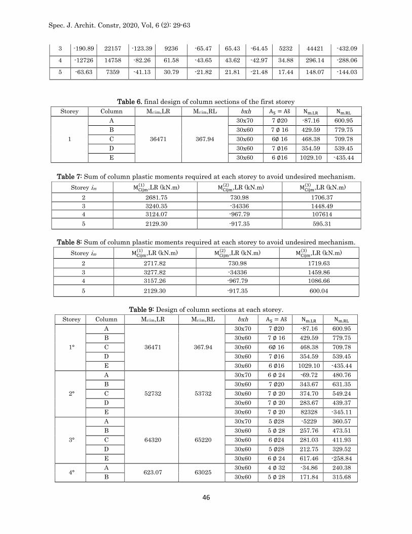
According to the global mechanism, axial forces in the columns at the collapse state depend both on the distributed loads on the beams and on the shears action due to the development of plastic hinges at the beam ends, as depicted in Fig. 6 from an earthquake from Left to Right. The first contribution to the vertical load on the columns is Nq, related to the vertical seismic loading combination (i.e. the sum of ql=2 type contributions). In Table 4 the axial forces due to vertical loads, for both directions of earthquake, are reported for each storey and for each column. The second component, NM;LR (or NM;RL), related to the shear actions is reported in Table 5. Therefore the required and obtained bending moment for each storey, the section, the upper and lower reinforcement and the axial force, for both directions of the earthquake are reported in Table 6. The sums of obtained column plastic moments at first storey are: Mc, Rd, 1, LR=2030.28kN.m kN m for LR earthquake and Mc,1,RL=2032.28kN for RL earthquake which are greater than the required one.
The value of 𝛼0(𝑔) obtained from Eq. (5) for LR earthquake and from Eq. (6) for RL earthquake are
equal to 𝛼0,𝐿𝑅(𝑔) =3.0468, 𝛼0,𝑅𝐿(𝑔) = 3.0648,
(h) Computation of the required sum of plastic moments of columns 𝑀𝑐,𝑖𝑚(𝑡) at any storey, to avoid
undesired mechanism by means of Eqs. (38) (or (39) for RL earthquake), (40) (or (41) for RL earth-quake) and (42) (or (43) for RL earthquake).

Spec. J. Archit. Constr, 2020, Vol, 6 (2): 29-63
45
So for earthquake from Left to Right the sum of column plastic moments required at each storey to avoid undesired mechanisms is reported in Table 7. And for earthquake from Right to Left the same sum is reported in Table 8. The plastic moments of columns governing the column design at each storey (Eqs. (44) and (45)) are reported in Tables 7 and 8 and underlined. For the specific case study, the need to avoid a type-1 mechanism governs the design of columns.
(i) and (j) Design of column sections at each storey. The required sum of column plastic moments Mc;i;im , the section, the upper and lower reinforcement, the axial force for both direc-tions of the earthquake are reported in Table 9.
(k) Checking of technological condition. A technological condition is considered by imposing that the column section at each storey cannot be greater than the one of the storey below. From Tables 6 and 9 it can be noted that some column section at the first storey is smaller than the cross-section of the same column at the second storey (e. g. column A). As a consequence, the values of obtained column plastic moments at first storey need to be updated. In particular, by using the same internal actions (Table 6) and the section dimensions required by technological condition (Table 9), the new design of first storey columns (Table 12) leads to obtain Mc, Rd, 1, RL=2098.26kN.m and Mc, Rd, 1, LR=2125.80kN.m, and the procedure can be repeated from step (e). In Tables 10 and 11 the new value of required plastic moments at any storey are reported for both directions of earthquake. The final geometry and reinforcement for all the columns are reported in Table 12.
Fig. 6. Loads transmitted by the beams to the columns at collapse state for LR earthquake.
Table 5. axial forces imposing on columns caused by shear forces
Storey im
Column A Column B Column C Column D Column E Nm.LR [kN)
Nm.RL [kN] Nm.LR [kN)
Nm.RL [kN] Nm.LR [kN] Nm.RL [kN]
Nm.LR [kN)
Nm.RL [kN]
Nm.LR [kN) Nm.RL [kN]
1 -318.16 36955 -205.66 144.50 -109.12 13228 -107.41 77.45 74035 -724.18
2 -254.52 29556 -164.53 123.15 -8730 8724 -85.93 69.77 59228 -576.11
Spec. J. Archit. Constr, 2020, Vol, 6 (2): 29-63
46
3 -190.89 22157 -123.39 9236 -65.47 65.43 -64.45 5232 44421 -432.09
4 -12726 14758 -82.26 61.58 -43.65 43.62 -42.97 34.88 296.14 -288.06
5 -63.63 7359 -41.13 30.79 -21.82 21.81 -21.48 17.44 148.07 -144.03
Table 6. final design of column sections of the first storey Storey Column Mc;im,LR Mc;im,RL bxh AS = As̃ Nm.LR Nm.RL
1
A
36471 367.94
30x70 7 ∅20 -87.16 600.95
B 30x60 7 ∅ 16 429.59 779.75
C 30x60 6∅ 16 468.38 709.78
D 30x60 7 ∅16 354.59 539.45
E 30x60 6 ∅16 1029.10 -435.44
Table 7: Sum of column plastic moments required at each storey to avoid undesired mechanism.
Storey im MCijm(1) ,LR (kN.m) MCijm(2) ,LR (kN.m) MCijm(3) ,LR (kN.m)
2 2681.75 730.98 1706.37 3 3240.35 -34336 1448.49 4 3124.07 -967.79 107614
5 2129.30 -917.35 595.31
Table 8: Sum of column plastic moments required at each storey to avoid undesired mechanism.
Storey im MCijm(1) ,LR (kN.m) MCijm(2) ,LR (kN.m) MCijm(3) ,LR (kN.m)
2 2717.82 730.98 1719.63
3 3277.82 -34336 1459.86 4 3157.26 -967.79 1086.66
5 2129.30 -917.35 600.04
Table 9: Design of column sections at each storey. Storey Column Mc;im,LR Mc;im,RL bxh AS = As̃ Nm.LR Nm.RL
1°
A
36471 367.94
30x70 7 ∅20 -87.16 600.95
B 30x60 7 ∅ 16 429.59 779.75
C 30x60 6∅ 16 468.38 709.78
D 30x60 7 ∅16 354.59 539.45
E 30x60 6 ∅16 1029.10 -435.44
2°
A
52732 53732
30x70 6 ∅ 24 -69.72 480.76
B 30x60 7 ∅20 343.67 631.35
C 30x60 7 ∅ 20 374.70 549.24
D 30x60 7 ∅ 20 283.67 439.37
E 30x60 7 ∅ 20 82328 -345.11
3°
A
64320 65220
30x70 5 ∅28 -5229 360.57
B 30x60 5 ∅ 28 257.76 473.51
C 30x60 6 ∅24 281.03 411.93
D 30x60 5 ∅28 212.75 329.52
E 30x60 6 ∅ 24 617.46 -258.84
4° A
623.07 63025 30x60 4 ∅ 32 -34.86 240.38
B 30x60 5 ∅ 28 171.84 315.68

Spec. J. Archit. Constr, 2020, Vol, 6 (2): 29-63
47
C 30x60 6 ∅24 187.35 274.62
D 30x60 5 ∅28 141.83 219.68
E 30x60 6 ∅ 24 411.64 -172.56
5°
A
42159 425.86
30 x 50 6 ∅ 24 -17.43 120.19
B 30x50 6 ∅ 24 85.92 157.84
C 30 x 50 6 ∅ 24 93.68 137.31
D 30 x 50 6 ∅ 24 70.92 109.84
E 30 x 50 6 ∅ 24 205.82 -86.28
Table 10: Sum of column plastic moments required at each storey for LR earthquake.
Storey im MCijm(1) ,LR (kN.m) MCijm(2) ,LR (kN.m) MCijm(3) ,LR (kN.m)
2 2636,60 800.45 1718.52
3 3216,04 -298.20 1458.91 4 3115.39 -943.47 1085.95
5 2107.97 -908.66 599.65
Table 11: Sum of column plastic moments required at each storey for RL earthquake.
Storey im MCijm(1) ,LR (kN.m) MCijm(2) ,LR (kN.m) MCijm(3) ,LR (kN.m)
2 26S6.63 769.42 1728.02 3 3261,03 -326.91 1467.06 4 315127 -967.13 1092.06
5 2129*30 -92321 603.04
Table 12: Design of column sections at each storey for both directions of the earthquake. Storey Column Mc;im,LR Mc;im,RL bxh AS = As̃ Nm.LR Nm.RL
1°
A
36471 367.94
30x70 7 ∅20 -87.16 600.95
B 30x60 7 ∅ 16 429.59 779.75
C 30x60 6∅ 16 468.38 709.78
D 30x60 7 ∅16 354.59 539.45
E 30x60 6 ∅16 1029.10 -435.44
2°
A
52732 53732
30x70 6 ∅ 24 -69.72 480.76
B 30x60 7 ∅20 343.67 631.35
C 30x60 7 ∅ 20 374.70 549.24
D 30x60 7 ∅ 20 283.67 439.37
E 30x60 7 ∅ 20 82328 -345.11
3°
A
64320 65220
30x70 5 ∅28 -5229 360.57
B 30x60 5 ∅ 28 257.76 473.51
C 30x60 6 ∅24 281.03 411.93
D 30x60 5 ∅28 212.75 329.52
E 30x60 6 ∅ 24 617.46 -258.84
4°
A
623.07 63025
30x60 4 ∅ 32 -34.86 240.38
B 30x60 5 ∅ 28 171.84 315.68
C 30x60 6 ∅24 187.35 274.62
D 30x60 5 ∅28 141.83 219.68
E 30x60 6 ∅ 24 411.64 -172.56
5° A 42159 425.86 30 x 50 6 ∅ 24 -17.43 120.19

Spec. J. Archit. Constr, 2020, Vol, 6 (2): 29-63
48
B 30x50 6 ∅ 24 85.92 157.84
C 30 x 50 6 ∅ 24 93.68 137.31
D 30 x 50 6 ∅ 24 70.92 109.84
E 30 x 50 6 ∅ 24 205.82 -86.28
Validation of the design procedure In order to validate the design procedure, a static non-linear analysis (push-over) has been carried out in SAP2000 (SAP, 2007) in order to investigate the actual seismic performance of the designed frame. This analysis has the primary goal to confirm the development of the desired collapse mechanism typology and to evaluate the energy dissipation capacity while testing the accuracy of the proposed design methodology. In the structural model, the mechanical non-linearities, have been concentrated at beam and column ends by means of plastic hinge elements. The constitutive law of such plastic hinges is provided by a rigid plastic moment– rotation curve. The type of hinge depends on the element considered i.e. by its internal action. For the beams and the columns M3 and P-M3 hinge type have been considered, respectively. In case of P-M3 hinge type, the interaction domain has been evaluated for each column. The results of the push-over analysis are expressed as base shear–top sway displacement curves presented in Fig. 7. In the same figure a straight line provides the linearized equilibrium curve of global mechanism with equation:
( ) 3.0468 0.003167g
LR = − (57)
( ) 3.0468 0.003167g
RL = − (58)
for LR and RL earthquake, respectively. The difference between the LR and RL push-over curves of Fig. 7 must be ascribed to the variation in columns axial forces, as a con-sequence, also the corresponding plastic moments are different. Despite their close proximity curves should be always considered when a non-symmetric moment-resisting frame is analyzed. The base shear is obtained by multiplying the value of a, from Eqs. (57) and (58) by the design base shear (value). The comparison between the push-over curve and the global equilibrium curve provides a first confirmation of the accuracy of the proposed design procedure because when a collapse mechanism is completely developed, the corresponding branch of the push-over curve represents the equilibrium curve of the developed mechanism. In fact, as showed in Fig. 7, push-over curves are very close and parallel to the global mechanism equilibrium curves. The fulfilment of the design objective is also confirmed by the yielding pattern developed at the occurrence of the design ultimate displacement. The developed plastic hinges are shown in Fig. 8 and their distribution is in agreement with the global mechanism. The serviceability condition requires the interstorey drift to be compared with limit value reported in the Eurocode 8 (EN, 1998). For buildings with nonstructural elements of brittle materials the limit condition is:
0.005rd v h (59)
where dr is the design interstorey drift, evaluated as the difference between the lateral displacements ds at the top and bottom of the storey under consideration, m is the reduction factor which takes into account the lower return period of the seismic action associ-ated with the damage limitation requirement and h is the corre-sponding interstorey height. The value of the reduction factor m depend

Spec. J. Archit. Constr, 2020, Vol, 6 (2): 29-63
49
on the importance class of the building (a value of v=0.5 was adopted). In Table 13 the interstorey limits are reported together the absolute ds and relative dr displacements. If this serviceability requirement is not verified the structural stiffness can be improved by increasing the beam sections or the ultimate design displacement. In fact, in both cases the final results will be a more rigid structure with respect to the one obtained in the worked example herein presented. In several codes recommended values of the strong-column/ weak-beam (SCWB) ratio can be found. ACI 318 M-11 – 21.6.2.2 ( Standard, 2011), states that at the face of a joint the sum of the nominal moments of the columns framing into the joint shall be greater than the sum of the flexural strengths of the beams by a factor of 1.2, unique value of the SCWB for all points is not able to assure the development of a global mechanism. while the Eurocode 8 (EN, 1998) requires a factor of 1.3 for the column-to beam design flexural strength ratio. Also Paulay and Priestly (Paulay and Priestley, 1992) agree that this factor should not be less than 6/5 since it is sufficient to ensure that a ‘‘soft-storey” will not develop even if they suggest a factor of 1.5. Fig. 9 shows as the SCWB ratios, reported for both directions of earthquake, are bigger than 1.2 in each joint but even bigger than 1.3 that is the recommended value of Eurocode 8 used for the design of the frame. In addition, it is evident that there is a big variability in such ratios. This result shows that the condition which requires a minimum unique value of the SCWB for all points is not able to assure the development of a global mechanism. To provide a more robust validation of the design methodology, non-linear incremental dynamic analyses have been developed for the same structural model used for push-over analyses and with the same computer program (SAP, 2007). Seven recorded accelerograms from the PEER data base were selected (Pacific Earthquake Engineering Research Center), the main characteristics of the records (name, date, magnitude, ratio between PGA and gravity acceleration, length and sampling rate) are provided in Table 14. These earthquake records have been selected to approximately match the linear elastic design response spectrum of Eurocode 8, for type A soil. The average and the scatter of the selected spectra are compared to the elastic code spectrum in Fig. 10
Fig. 7. Overlap of the push-over curve with the global mechanism equilibrium curve.

Spec. J. Archit. Constr, 2020, Vol, 6 (2): 29-63
50
Fig. 8. Pattern of yielding of the designed frame at δ=δu for LR and RL earthquake direction
Table 13. Interstorey drift limits.
Storey ds [mm] dr [mm] 𝑣 dr u[mm] 0.005h [mm]
5 6.2448 0.8497 0.5 0.4248 1.5
4 5.3950 1.2280 0.6140 1.5
3 4.1669 1.5483 0.7741 1.5
2 2.6186 1.6274 0.8137 1.5
1 0.9911 0.9911 0.4955 1.5
Fig. 9. SCWB ratios of the 5 storey frame for LR and RL earthquake direction.
Table 14: Accelerogram characteristics.
Earthquake (record) Component Date PGA/g Length [s] Sampling rate
Kobe (Kakogawa) KAK000 1995/01/16 0.251 40.95 0.01
Northridge (Stone Canyon) SCR000 1994/01/17 0.252 39.99 0.01
Palm Springs (Soboba) H08000 1986/07/08 0.250 26.00 0.005
Santa Barbara (Courthouse) SBA132 1978/08/13 0.102 12.57 0.01
Spitak Armenia (Gukasian) GUK000 1988/07/12 0.199 19.89 0.01
Duzce, Turkey (Lamont) 375-N 1999/11/12 0.97 41.50 0.01
Victoria Mexico (Chihuahua) CHI102 1980/06/09 0.150 26.91 0.01

Spec. J. Archit. Constr, 2020, Vol, 6 (2): 29-63
51
Fig. 10. Comparison of the average and the scatter of the selected spectra with the elastic code
spectrum.
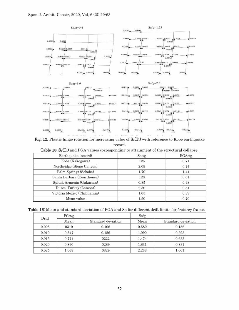
In order to perform IDA analyses, each ground motion has been scaled to obtain the same value of the spectral acceleration Sa(T1) associated to the fundamental period of vibration T1 of the structure (T1=0.54). This is the seismic intensity measure (IM) adopted for IDA analyses where Sa(T1) values have been progressively increased. In Fig. 11, the maximum interstorey drift ratio (MIDR) is reported versus the spectral acceleration. For each record the yielding pattern has been monitored for increasing values of Sa(T1) and the plastic hinges development is always in agreement with the global mechanism.
Fig. 11. Maximum interstorey drift ratio versus Sa(T1)
Spec. J. Archit. Constr, 2020, Vol, 6 (2): 29-63
52
Fig. 12. Plastic hinge rotation for increasing value of Sa(T1) with reference to Kobe earthquake
record. Table 15: Sa(T1) and PGA values corresponding to attainment of the structural collapse.
Earthquake (record) Sac/g PGAc/g
Kobe (Kakogawa) 125 0.71
Northridge (Stone Canyon) 2.09 0.74
Palm Springs (Soboba) 1.70 1.44
Santa Barbara (Courthouse) 123 0.61
Spitak Armenia (Gukasian) 0.85 0.48
Duzce, Turkey (Lamont) 2.30 0.54
Victoria Mexico (Chihuahua) 1.05 0.39
Mean value 1.50 0.70
Table 16: Mean and standard deviation of PGA and Sa for different drift limits for 5-storey frame.
Drift PGA/g Sa/g
Mean Standard deviation Mean Standard deviation
0.005 0319 0.106 0.589 0.186
0.010 0.547 0.156 1.090 0.393
0.015 0.724 0222 1.474 0.633
0.020 0.890 0289 1.831 0.831
0.025 1.069 0329 2.233 1.001

Spec. J. Archit. Constr, 2020, Vol, 6 (2): 29-63
53
Fig. 13. Structural scheme of ten-storey designed frame.
Table 18: Axial forces acting in the columns related to the vertical loads for both directions of earthquake.
Storey
im Column A Nq [kN] Column B Nq[kN] Column C Nq[kN] Column D Nq[kN]
Column E
Nq [kN]
1 462.00 1270.50 1155.00 924.00 577.50
2 415.80 1143.45 1039.50 831.60 519.75
3 369.60 1016.40 924.00 739.20 462.00
4 323.40 889.35 808.50 646.80 40425
5 21120 762.30 693.00 554.40 346.50
6 231.00 635.25 577.50 462.00 288.75
7 184.80 50820 462.00 369.60 231.00
8 138.60 381.15 346.50 277.20 17325
9 92.40 254.10 231.00 184.80 115.50
10 46.20 127.05 115.50 92.40 57.75
Fig. 12 provides the distribution of plastic hinges for increasing value of Sa(T1) with reference to Kobe earthquake record. As it can be noted, for a value of Sa(T1)/g=1.25 there is a plastic hinge which reaches the design value of 0.01 rad, if the actual capacity of the section is not greater than 0.01 rad, collapse can be considered as achieved. On the contrary, a bigger value of spectral acceleration can be reached, if a greater capacity of the beam sections is available. The frames present some spurious hinges at the column ends of some storeys. In addition, the average value of Sa(T1) leading to col-lapse is near to 1.50 g while the average PGA is about 0.70 g. Indeed,

Spec. J. Archit. Constr, 2020, Vol, 6 (2): 29-63
54
these hinges are displayed by the SAP2000 but their plastic rotation is very close to zero so that they do not participate in the development of the collapse mechanism. The spectral acceleration values leading to a plastic hinge rotation equal to 0.01, given in Table 15, are very high and compatible with the adoption of the designed structure even in case of destructive earthquakes. In addition, in order to show the variability of the results with the considered ground motions, in Table 16 the average and the standard deviation of Sa(T1)/g values, corresponding to different drift limits, have been reported. To guarantee the effectiveness of the proposed procedure another test problem, the seismic design of a four-bay ten-storey moment resisting frame, is presented (Fig. 13). As already stated, for this application a value of θu=0.02 is used. According to Eurocode 8, the value of the period of vibration to be used for preliminary design is:
3/4 3/40.075 0.075.30 0.96T H s= = (60)
The interstorey height is equal to 3 m. The structural materials, permanent (Gk) and live (Qk) actions are the same adopted in the previous example. According to proposed procedure the design value of the top sway displacement can be determined as:
0.02. 0.02.30 0.60u nsh m = = = (61)
The reinforcements at the beam ends, reported in Table 17, are the same at all the storeys. In Table 18 the axial forces due to vertical loads, for both directions of earthquake, are reported for each storey and for each column. Finally the values of NM;LR and NM;RL are in Table 19.
For shortness reason, for this application, all the steps seen for the first example are not reported. Therefore, before obtaining the final columns it was necessary, initially, to solve a technological condition on the first floor and then one on the upper floors. In Table 20 are reported the final values of the columns. Fig. 14 shows the results of the push-over analysis. In the same figure a straight line provides the linearized equilibrium curve of global mechanism with equation: and:
( ) 2.3868 0.002558g
LR = − (62)
( ) 2.4299 0.002558g
RL = − (63)
for LR and RL earthquake, respectively.
Table 19. axial forces imposing on the columns related to the shear forces for both directions of earthquake
Storey
Column A Column B Column C Column D Column E Nm.LR
[kN]
Nm.RL
[kN]
Nm.LR
[kN]
Nm.RL
[kN]
Nm.LR
[kN]
Nm.RL
[kN]
Nm.LR
[kN]
Nm.RL
[kN]
Nm.LR
[kN]
Nm.RL
[kN]
1 -84423 740.65 -14.40 21223 -68433 452.19 562.16 -316.91 980.80 -1088.16
2 -759.81 666.58 -12.% 191.01 -615.90 40637 505.94 -285.22 882.72 -97935

Spec. J. Archit. Constr, 2020, Vol, 6 (2): 29-63
55
3 -67538 592.52 -11.52 169.78 -547.47 361.75 449.73 -253.53 784.64 -87033
4 -590.96 518.45 -10.08 14836 -479.03 31634 39331 -221.83 686.56 -761.71
5 -50634 444.39 -8.64 12734 -410.60 27132 33730 -190.14 588.48 -65230
6 -422.11 37032 -7.20 106.11 -342.17 226.10 281.08 -158.45 490.40 -544.08
7 -337.69 29626 -5.76 84.89 -273.73 180.88 224.86 -126.76 39232 -43526
8 -25327 222.19 -4.32 63.67 -20530 135.66 168.65 -95.07 29424 -326.45
9 -168.85 148.13 -2.88 42.45 -136.87 90.44 112.43 -63.38 196.16 -217.63
10 -84.42 74.06 -1.44 2122 -68.43 45.22 5622 -31.69 98.08 -108.82
Table 20. Design of column sections in every storey
Storey Column Mc;im,LR Mc;im,RL bxh AS = As̃ Nm.LR Nm.RL
1
A
55239 55806
30.83 6∅ 24 -38223 120265
B 30x90 7∅ 16 125610 148273
C 30x90 7∅ 16 47Û67 1607.19
D 30x90 7∅ 16 148616 637.(8
E 30x70 7∅ 16 1558-30 -51066
2
A
59433 60228
30x83 6∅ 24 -34401 108238
B 30x83 5 ∅ 20 113649 133446
C 30x90 7∅ 16 43260 144647
D 30x83 6∅ 16 1337-54 54638
E 30x70 5 ∅ 20 140247 -45963
3
A
75895 77053
30x83 4 ∅ 32 -305.78 96212
B 30x70 6∅ 24 100488 118618
C 30x90 6∅ 20 37653 128575
D 30x70 7 ∅ 20 118893 48567
E 30x70 7 ∅ 20 124664 -40853
4
A
89072 905-30
30x83 5 ∅ 32 -26756 84185
B 30x70 4 ∅ 32 87927 103791
C 30x83 6∅ 24 32947 112504
D 30x70 6∅ 24 1040-31 42497
E 30x70 5 ∅ 28 1(8081 -357.46
5
A
97870 99542
30x83 5 ∅ 32 -22934 72159
B 30x 70 5 ∅ 32 75266 88964
C 30x 70 5 ∅ 32 28240 96432
D 30x 70 4 ∅ 32 891.70 36426
E 30x 70 4 ∅ 32 93498 -30643
6
A
101193 102974
30x83 5 ∅ 32 -191.11 60132
B 30x 70 5 ∅ 32 62805 74136
C 30x70 5 ∅ 32 23533 63263
D 30x70 5 ∅ 32 74208 30255
E 30x70 5 ∅ 32 77915 -25533
7
A
97946 997.10
30x83 5 ∅ 32 -15289 481.06
B 30x70 5 ∅ 32 50244 592(8
C 30x70 5 ∅ 32 18827 64288
D 30x70 5 ∅ 32 59446 24284

Spec. J. Archit. Constr, 2020, Vol, 6 (2): 29-63
56
E 30x70 5 ∅ 32 62232 -20426
8
A
87035 88633
30x70 5 ∅ 32 -11467 36079
B 30x70 5 ∅ 32 37683 44482
C 30x70 5 ∅ 32 14120 48216
D 30x70 5 ∅ 32 44585 18213
E 30x70 4 ∅ 32 467.49 -15220
9
A
67364 68627
30x70 5 ∅ 28 -7645 24053
B 30x83 4 ∅ 32 25122 29655
C 30x83 5 ∅ 28 9413 321.44
D 30x83 5 ∅ 28 29723 121.42
E 30x83 5 ∅ 28 311.66 -10213
10
A
37840 38577
30x50 6∅ 24 -3822 12026
B 30x 50 7 ∅ 20 12561 14827
C 30x 50 7 ∅ 20 47.07 16072
D 30x 50 7 ∅20 14862 6Û71
E 30x50 7 ∅20 15583 -5197
Fig. 14. Overlap of the push-over curve with the global mechanism equilibrium curve for ten-storey
frame.

Spec. J. Archit. Constr, 2020, Vol, 6 (2): 29-63
57
Fig. 15. Overlap of the global mechanism equilibrium curve with the push-over evaluated for a value
of Young’s modulus equal to 10 times the original one. As already stated, the upper bound theorem of plastic collapse is based on a rigid- perfectly-plastic behavior, i.e. the elastic behavior is completely neglected. In fact, the first part of push-over curve is not coincident with the theoretical mechanism equilibrium curve due to the elastic effects. When a collapse mechanism is completely developed then the last branch of push-over curve is obtained. This last branch represents the equilibrium curve of the developed mechanism (Figs. 7 and 14). To better show this aspect, the push-over curve of the 10-storey structure has been evaluated with a value of Young’s modulus equal to 10 times the original one. From Fig. 15 it is evident that the elastic behavior is concentrated in the first 12 cm of top displacement, after that, the push-over is practically coincident with the global mechanism equilibrium curve. At the limit, if the push-over is evaluated with an elastic modulus equal to infinite, the push-over curve is coincident with the global mechanism equilibrium curve from the beginning of the top displacement. In Fig. 16 the developed plastic hinges are shown for both static push-over analyses. Their distribution is again in agreement with the global mechanism. For buildings having non-structural elements of brittle materials attached to the structure the limitation of interstorey drift, regarding the serviceability condition, is given by Eq. (59) and the results are reported in Table 21. As in the previous study case, also in this analyzed structure, the SCWB ratios are major of the value 1.2 as provided by the ACI-318, confirming the result already obtained (see Fig. 17)

Spec. J. Archit. Constr, 2020, Vol, 6 (2): 29-63
58
Fig. 16. Pattern of yielding of the 10 storey frame for δ=δu for LR and RL earthquake direction.
Table 21: Interstorey drift limits.
Storey ds [mm] dr [mm] 𝑣 dr u[mm] 0.005h [mm] 10 14.087 0.6632 0.5 03316 1.5 9 13.3455 0.9615 0.4807 1.5 8 12.3840 1.2009 0.6004 1.5 7 11.1830 1.4540 0.7270 1.5 6 9.7290 1.6772 0.8386 1.5 5 8.0518 1.8544 0.9272 1.5 4 6.1973 1.9344 0.9672 1.5 3 4.2628 1.8952 0.9476 1.5 2 2.3675 1.5921 0.7960 1.5 1 0.7754 0.7754 03877 1.5
Also for this second frame IDA have been made by using the same set of ground motions. Each ground motion has been scaled to obtain the same value of the spectral acceleration Sa(T1) associated to the fundamental period of vibration T1 of the structure ((T1=1.04s)). In Fig. 18 the distribution of plastic hinges for increasing value of Sa(T1) with reference to Santa Barbara earthquake record is reported. In this case, for a value of Sa(T1)/g=1.10 there is a plastic hinge which reaches the design value of 0.02 rad, if the actual capacity of the section is not greater than 0.02 rad, collapse can be considered as achieved. As for the previous study case, the yielding pattern has been monitored for increasing values of Sa(T1) for each record and the

Spec. J. Archit. Constr, 2020, Vol, 6 (2): 29-63
59
Fig. 17. SCWB ratios of the 10 storey frame for LR and RL earthquake direction.

Spec. J. Archit. Constr, 2020, Vol, 6 (2): 29-63
60
Fig. 18. Pattern of yielding for increasing value of Sa(T1) with reference to Santa Barbara earthquake
record. Table 22: Mean and standard deviation of PGA and Sa for different drift limits for 10-storey frame.
Drift PGA/g Sa/g
Mean Standard deviation Mean Standard deviation
0.005 0.312 0.167 0217 0.097
0.010 0.750 0.399 0.465 0.340
0.015 1.019 0.509 0.726 0.352
0.020 1.235 0.726 0.969 0.414
0.025 1.633 0.818 1.188 0.508
0.030 2.124 1.397 1.50 0.711
plastic hinges development is always in agreement with the global mechanism. Finally, in Table 22, the average and the standard deviation of Sa(T1)/g values corresponding to different drift limits have been reported. Conclusions In this paper a methodology called Theory of Plastic Mechanism Control (TPMC) for the design of RC moment resisting frames has been presented. On the base of the extension of the kinematic theorem of plastic collapse to the concept of mechanism equilibrium curve, the Theory of Plastic Mechanism

Spec. J. Archit. Constr, 2020, Vol, 6 (2): 29-63
61
Control allows to evaluate the sum of plastic moments of the columns, required at each storey, in order to develop a collapse mechanism of global type. The closed form solution of the design conditions makes the design procedure very easy to be applied even by means of hand calculations and, therefore, it could also be suggested by codes as solution to the problem of collapse mechanism control whose importance in seismic design is universally recognized. Beam– column hierarchy criterion, commonly suggested by seismic codes, appears only as a very rough approximation when compared to TPMC and its theoretical background. The reliability of the pro-posed design procedure has been also validated through its application to a four-bays, five-storey frame, leading to the fulfilment of the design objective, i.e. the development of a collapse mechanism of global type. The results of both push-over analysis and non-linear dynamic analyses confirm the theoretical results. In addition, it can be noted that the proposed procedure constitutes a rigorous application of the capacity design principles. Beams are, in fact, designed in order to bear external loads, while columns are designed according to the maximum internal actions transmitted by the dissipative zones. The proposed procedure can be applied for MRFs characterized by a non-symmetric geometry and a non-symmetric reinforcement distribution in each beam cross-section.
References
1. Bai, J., & Ou, J. (2015). Realization of the global yield mechanism of RC frame structures by redesigning the columns using column tree method. Science China Technological Sciences, 58(10), 1627-1637.
2. D’Aniello M, Della Corte G, & Mazzolani FM. (2006). Seismic upgrading of RC buildings by steel eccentric braces: experimental results vs numerical modeling. In: Proceedings of the 5th international conference on behaviour of steel structures in seismic areas – Stessa 200, Yokohama; Japan; 14–17, 809–814.
3. D’Aniello M, Della Corte G, & Mazzolani FM. (2006). Seismic upgrading of RC buildings by buckling restrained braces: experimental results vs numerical modeling. In: Proceedings of the 5th international conference on behaviour of steel structures in seismic areas – Stessa 200, Yokohama; Japan; 14–17 August, 2006. 809–814.
4. Della Corte, G., D’Aniello, M., & Landolfo, R. (2015). Field testing of all-steel buckling-restrained braces applied to a damaged reinforced concrete building. Journal of structural engineering, 141(1), D4014004.
5. EN (1998). Eurocode 8: design of structures for earthquake resistance – Part 1: General rules, seismic actions and rules for buildings, CEN; 2004.
6. Godínez-Domínguez, E. A., & Tena-Colunga, A. (2010). Nonlinear behavior of code-designed reinforced concrete concentric braced frames under lateral loading. Engineering Structures, 32(4), 944-963. http://dx.doi.org/10.1016/j.engstruct.2009.12.020.
7. Han, J., Li, Y. M., & Ji, S. Y. (2010). Realization of rational failure mechanism for the RC frame structure. Journal of Harbin Institute of Technology, 42(12), 2003-2008.
8. Heidari, A., & Gharehbaghi, S. (2015). Seismic performance improvement of special truss moment frames using damage and energy concepts. Earthquake Engineering & Structural Dynamics, 44(7), 1055-1073. http://dx.doi.org/10.1002/eqe.2499.
9. Hejazi, F., Kojouri, S. J., Noorzaei, J., Jaafar, M. S., Thanoon, W. A., & Abdullah, A. (2011). Inelastic seismic response of RC building with control system. In Key engineering materials (Vol. 462, pp. 241-246). Trans Tech Publications Ltd. http://dx.doi.org/10.4028/www.scientific.net/ KEM.462-463.241.

Spec. J. Archit. Constr, 2020, Vol, 6 (2): 29-63
62
10. Hejazi, F., Noorzaei, J., Jaafar, M. S., Abdullah, A. A. A. (2009). Earthquake analysis of reinforce concrete framed structures with added viscous dampers. World Acad Sci Eng Technol 38; 205-210.
11. Hejazi, F., Zabihi, A., & Jaafar, M. S. (2014). Development of elasto-plastic viscous damper finite element model for reinforced concrete frames. Soil Dynamics and Earthquake Engineering, 65, 284-293. http://dx.doi.org/10.1016/j.soildyn.2014.06.008.
12. Hwang, J. S., Tsai, C. H., Wang, S. J., & Huang, Y. N. (2010). Applications of viscous dampers to RC structures with lightly reinforced concrete walls. In: Wind and earthquake engineering. proceedings of the 10th East Asia-Pacific conference on structural engineering and construction, EASEC 2010, vol. 3; 2006. 315–320.
13. Lee, H. S. (1996). Revised rule for concept of strong-column weak-girder design. Journal of Structural Engineering, 122(4), 359-364.
14. Leelataviwat, S., Goel, S. C., & Stojadinović, B. (2002). Energy-based seismic design of structures using yield mechanism and target drift. Journal of Structural Engineering, 128(8), 1046-1054.
15. Longo, A., Montuori, R., & Piluso, V. (2012). Failure mode control and seismic response of dissipative truss moment frames. Journal of Structural Engineering, 138(11), 1388-1397.
16. Longo, A., Montuori, R., & Piluso, V. (2014). Theory of plastic mechanism control for MRF–CBF dual systems and its validation. Bulletin of Earthquake Engineering, 12(6), 2745-2775.
17. Longo, A., Montuori, R., & Piluso, V. (2016). Moment frames–concentrically braced frames dual systems: analysis of different design criteria. Structure and infrastructure engineering, 12(1), 122-141.
18. Mahrenholtz, C., Lin, P. C., Wu, A. C., Tsai, K. C., Hwang, S. J., Lin, R. Y., & Bhayusukma, M. Y. (2015). Retrofit of reinforced concrete frames with buckling‐restrained braces. Earthquake Engineering & Structural Dynamics, 44(1), 59-78. http://dx.doi.org/10.1002/eqe.2458.
19. Mazzolani, F. M., & Piluso, V. (1997). Plastic design of seismic resistant steel frames. Earthquake engineering & structural dynamics, 26(2), 167-191.
20. Mazzolani, F. M., Corte, G. D., & D'Aniello, M. (2009). Experimental analysis of steel dissipative bracing systems for seismic upgrading. Journal of Civil Engineering and Management, 15(1), 7-19.
21. Mistakidis, E. S., De Matteis, G., & Formisano, A. (2007). Low yield metal shear panels as an alternative for the seismic upgrading of concrete structures. Advances in Engineering Software, 38(8-9), 626-636.
22. Montuori, R., & Muscati, R. (2015). Plastic design of seismic resistant reinforced concrete frame. Earthquakes and Structures, 8(1), 205-224.
23. Montuori, R., Nastri, E., & Piluso, V. (2014). Theory of plastic mechanism control for eccentrically braced frames with inverted Y-scheme. Journal of Constructional Steel Research, 92, 122-135.
24. Montuori, R., Nastri, E., & Piluso, V. (2015). Advances in theory of plastic mechanism control: closed form solution for MR‐Frames. Earthquake Engineering & Structural Dynamics, 44(7), 1035-1054.
25. New Zealand Standard code of practice for the design of concrete structures, (1982). NZS 3101: Part 1; Commentary NZS 3101: Part 2; Standard Association of New Zealand, Wellington, New Zealand.
26. Oviedo, JA, Midorikawa, M, & Asari, T. (2010). Earthquake response of ten-story story-drift-controlled reinforced concrete frames with hysteretic dampers. Eng Struct 32(6):1735–46. http://dx.doi.org/10.1016/j.engstruct.2010.02.025.
27. Pacific Earthquake Engineering Research Center. PEER strong motion database. <http://peer.berkeley.edu>.
Spec. J. Archit. Constr, 2020, Vol, 6 (2): 29-63
63
28. Park, R. (1986). Ductile design approach for reinforced concrete frames. Earthquake spectra, 2(3), 565-619.
29. Paulay T. (1977). Seismic Design of Ductile Moment Resisting Reinforced Concrete Frames, Columns: Evaluation of Actions. Bulletin of the New Zealand National Society for Earthquake Engineering, 10(2), 85–94.
30. Paulay, T. (1980). Deterministic design procedure for ductile frames in seismic areas. Special Publication, 63, 357-382.
31. Paulay, T., & Priestley, M. N. (1992). Seismic design of reinforced concrete and masonry buildings. New York: John Wiley & Sons Inc.
32. Piluso, V., Montuori, R., & Troisi, M. (2014). Innovative structural details in MR-frames for free from damage structures. Mechanics Research Communications, 58, 146-156.
33. SAP, C. (2007). Integrated finite element analysis and design of structures. Analysis reference. Computer and Structure Inc., University of California, Berkeley.
34. Standard, A. A. (2011, August). Building Code Requirements for Structural Concrete (ACI 318-11) and commentary – American Concrete Institute, ACI Committee 318, Farmington Hills (MI); 2011.
35. Verderame, G. M., De Luca, F., Ricci, P., & Manfredi, G. (2011). Preliminary analysis of a soft‐storey mechanism after the 2009 L'Aquila earthquake. Earthquake engineering & structural dynamics, 40(8), 925-944.
36. Vision, S. E. A. O. C. (1995). A framework for performance based design, Vol. I, II and III. Structural Engineers Association of California (SEAOC), Vision 2000 Committee. Sacramento (California); 1995.