thermal break technology for various construction types · 0.396 (0.686) - manufactured thermal...
TRANSCRIPT

Morrison Hershfield | Suite 310, 4321 Still Creek Drive, Burnaby, BC V5C 6S7, Canada | Tel 604 454 0402 Fax 604 454 0403 | morrisonhershfield.com
REPORT
Thermal Break Technology for Various Construction Types
Presented to:
Dieter Hardock Product Manager North America
Schöck Bauteile GmbH Vimbucher Straße 2 76534 Baden-Baden, Germany
Report No. 5131042.00 August 1, 2014
M:\PROJ\5131042\REPORT\MH_REPORT 2014 JULY.DOCX

TABLE OF CONTENTS
Page
1. INTRODUCTION 1
2. THERMAL ANALYSIS 5
2.1 Thermal Transmittance 5
2.1.1 Cantilevered Concrete 5
2.1.2 Concrete Parapets 6
2.1.3 Steel to Steel Connection 7
2.1.4 Steel to Concrete Connection 8
2.1.5 Poured-in Place Concrete Wall to Floor Slab 8
2.2 Interior Slab Surface Temperatures 9
2.2.1 Cantilevered Concrete 9
2.2.2 Concrete Parapet 10
2.2.3 Steel to Steel Connection 11
2.2.4 Steel to Concrete Connection 12
2.2.1 Poured-in Place Concrete Wall to Floor Slab 12
3. SUMMARY 13
APPENDIX A: Material and Assembly Data Sheets
APPENDIX B: Thermal Results Data Sheets
APPENDIX C: Thermal Resistance Tables
APPENDIX D: Design Condition Thermal Profiles

-1-
1. INTRODUCTION
Morrison Hershfield Ltd. (MH) was retained by Schöck Bauteile GmbH (Shoeck) to evaluate the thermal performance of their thermal break technology for a variety of common details. This report summarizes the predicted thermal performance of 18 different scenarios for various types of construction.
For this report, 5 types of details were examined:
A. Steel stud assembly with a cantilevered concrete balcony
B. Steel stud assembly at a concrete parapet and roof deck
C. Structural steel beam penetration through a steel stud assembly
D. Concrete floor slab to structural steel beam connection
E. Interior insulated poured-in place concrete at wall to floor slab interface
Each of these detail groups consists of the conventional construction method alongside the comparative thermal break solution offered by Schöck. Several types of steel stud clear walls were used in the analysis of scenarios A-D and were exterior insulated, or split insulated (exterior and interior insulated) with horizontal or vertical clip cladding attachments. For the steel beam connection details C and D, additional thermal isolator pad solutions were also investigated alongside the Schöck solutions. Tables 1-5 summarize the assemblies modeled for this report. In the detail numbering, the suffixes denote the following:
CC – Conventional Construction
TI – Thermal Isolator Solution
SA – Schöck Assembly Solution
More information on each detail, including model dimensions, material properties and assembly images are shown in Appendix A. In addition, the thermal information in this report is also included in the “Building Envelope Thermal Bridging Guide: Analysis, Applications and Insights”1, which contains methodology and a catalogue of details to assist designers in reducing thermal bridging in buildings. The Schöck details can be compared to a wider variety of similar types of construction details contained in the guide. Also included in the guide is a simple cost benefit analysis that includes construction costs and energy use/savings for a variety of design strategies, including scenarios utilizing Schöck products.
1 Guide to be published in April, 2014

-2-
Table 1: Cantilevered Concrete Projections with Steel Stud Assemblies
Detail Wall
Assembly Additional Detail Description
Co
nv
en
tio
na
l
Co
nst
ruc
tio
n
R-15
Exterior
Insulated
Steel Stud
Assembly
• A01-CC: Without insulation at
curb, continuous concrete
projection
• A02-CC: With insulation at curb,
continuous concrete projection
Ma
nu
fac
ture
d
The
rma
l B
rea
k
(Iso
ko
rb C
M2
0)
R-15
Exterior
Insulated
Steel Stud
Assembly
• A03-SA: Without insulation at curb,
Isokorb CM20 thermal break at
concrete projection
• A04-SA: With insulation at curb,
Isokorb CM20 thermal break at
concrete projection
Co
nv
en
tio
na
l
Co
nst
ruc
tio
n
R-15/R-12
Split
Insulated
Steel Stud
Assembly
• A05-CC: Without insulation at
curb, continuous concrete
projection
• A06-CC: With insulation at curb,
continuous concrete projection
Ma
nu
fac
ture
d T
he
rma
l
Bre
ak (
Iso
ko
rb C
M2
0)
R-15/R-12
Split
Insulated
Steel Stud
Assembly
• A07-SA: Without insulation at curb,
Isokorb CM20 thermal break at
concrete projection
• A08-SA: With insulation at curb,
Isokorb CM20 thermal break at
concrete projection

-3-
Table 2: Concrete Parapets with Concrete Roof Decks and Steel Stud Walls
Detail Wall
Assembly Detail
Co
nv
en
tio
na
l
Co
nst
ruc
tio
n
R-15/R-12
Split
Insulated
Steel Stud
Assembly,
R-20
Insulated
Roof Deck
• B01-CC: Parapet insulated on
exterior side only, continuous
concrete parapet bypassing
interior insulation
Ma
nu
fac
ture
d
The
rma
l B
rea
k
(Iso
ko
rb A
XT1
)
R-15/R-12
Split
Insulated
Steel Stud
Assembly,
R-20
Insulated
Roof Deck
• B02-SA: Parapet insulated on
exterior side only, Isokorb AXT1
thermal break at roof insulation
level
Table 3: Structural Steel Beam Penetrations through Steel Stud Walls
Detail Wall
Assembly Additional Detail Description
Co
nv
en
tio
na
l
Co
nst
ruc
tio
n
R-15/R-12
Split
Insulated
Steel Stud
Assembly
• C01-CC: Uninterrupted steel beam
The
rma
l Is
ola
tor
Pa
d
R-15/R-12
Split
Insulated
Steel Stud
Assembly
• C02-TI: Steel beams separated by:
o 5 mm pad, stainless steel bolts
o 5 mm pad, steel bolts
o 5 mm pad, stainless steel bolts,
with R-10 Insulation outboard of
flanges
o 10 mm pad, stainless steel bolts
o 10 mm pad, steel bolts
Ma
nu
fac
ture
d
The
rma
l B
rea
k
(Iso
ko
rb S
22
)
R-15/R-12
Split
Insulated
Steel Stud
Assembly
• C03-SA: Steel Beam separated by
Isokorb S22 thermal break

-4-
Table 4: Structural Steel Beam Connections to Concrete Floor Slabs
Detail Wall
Assembly Detail
Co
nv
en
tio
na
l
Co
nst
ruc
tio
n
R-15/R-12
Split
Insulated
Steel Stud
Assembly
• D01-CC: Steel beam bypassing
exterior insulation with direct
connection to concrete
The
rma
l Is
ola
tor
Pa
d
R-15/R-12
Split
Insulated
Steel Stud
Assembly
• D02-TI: Steel beam bypassing
exterior insulation with 10 mm
isolator pad at slab connection
Ma
nu
fac
ture
d
The
rma
l B
rea
k
(Iso
ko
rb K
S1
4)
R-15/R-12
Split
Insulated
Steel Stud
Assembly
• D03-SA:Steel beam outboard of
exterior insulation with Isokorb KS14
thermal break at slab connection,
in line with exterior insulation
Table 5: Interior Insulated Concrete Walls at the Floor Slab Interface
Detail Wall
Assembly Detail
Co
nv
en
tio
na
l
Co
nst
ruc
tio
n
R-10
Interior
Insulated
Poured-in-
Place
Concrete
• E01-CC: Continuous concrete
connection between wall and
floor slab, bypassing insulation
Ma
nu
fac
ture
d
The
rma
l B
rea
k
(Iso
ko
rb R
uth
erm
a
DF)
R-10
Interior
Insulated
Poured-in-
Place
Concrete
• E02-SA: Concrete wall and floor
slab connection with Isokorb
Rutherma DF thermal break

-5-
2. THERMAL ANALYSIS
Thermal analysis was completed using 3D heat transfer software from Siemens called Nx. The analysis utilized steady-state conditions, published thermal properties of materials, and information provided by Schöck for their product. The objectives of the thermal analysis were:
1. Determine thermal transmittance (U-value, linear transmittance and point transmittance) for all the scenarios listed in Tables 1-5.
2. Provide temperature indices for all scenarios at locations of interest for evaluating the risk of condensation.
For more information regarding the assumptions used for thermal modeling see Appendix B.
2.1 Thermal Transmittance
The thermal performance for each assembly was analyzed using the methodology put forth by ASHRAE 1365-RP2. Tables 6-11 show the thermal transmittance for each scenario. Each table contains the scenario reference, a brief description, the clear field U-value (thermal performance of the wall or roof away from the connection detail), the overall U-value of the modeled assembly, the linear or point transmittance of the connection detail and the percent reduction in heat loss. The percent reduction is based on the comparison between the linear or point transmittance of the detail and the conventional construction detail. More detailed results information for each scenario is given in Appendix B. R-value versions of the following Tables 6-11 are given in Appendix C.
2.1.1 Cantilevered Concrete
Table 6: Thermal Transmittance of Cantilevered Concrete Projections with Exterior Insulated Steel Stud Assemblies
Scenario Description
Clear Wall U-
value Btu/ft² ·hr ·°F
(W/m²K)
Overall U-
value Btu/ft2 ∙hr ∙°F
(W/m²K)
ψ
Btu/ft ·hr ·°F
(W/mK)
%
Reduction
in Heat
Loss
Co
nv
en
tio
na
l
Co
nst
ruc
tio
n
A01-CC Without insulation at
curb 0.088 (0.50) 0.148 (0.84) 0.584 (1.011) -
A02-CC With insulation at curb 0.088 (0.50) 0.138 (0.78) 0.485 (0.840) 17%
Ma
nu
fac
ture
d
The
rma
l B
rea
k
(Iso
ko
rb C
M20
)
A03-SA Without insulation at
curb 0.088 (0.50) 0.115 (0.65) 0.261 (0.452) 55%
A04-SA With insulation at curb 0.088 (0.50) 0.100 (0.57) 0.117 (0.203) 80%
2 Details of the model and calibration can be found in ASHRAE 1365-RP “Thermal Performance of Building Envelope Details for
Mid- and High-Rise Construction”, 2011

-6-
Table 7: Thermal Transmittance of Cantilevered Concrete Projections with Exterior and Interior Insulated Steel Stud Assemblies
Scenario Description
Clear Wall
U-value Btu/ft² ·hr ·°F
(W/m²K)
Overall U-
value Btu/ft2 ∙hr ∙°F
(W/m²K)
ψ
Btu/ft ·hr ·°F
(W/mK)
%
Reduction
in Heat
Loss
Co
nv
en
tio
na
l
Co
nst
ruc
tio
n
A05-CC Without insulation
at curb 0.054 (0.31) 0.116 (0.66) 0.612 (1.059) -
A06-CC With insulation at
curb 0.054 (0.31) 0.108 (0.61) 0.528 (0.914) 14%
Ma
nu
fac
ture
d
The
rma
l B
rea
k
(Iso
ko
rb C
M20
)
A07-SA Without insulation
at curb 0.054 (0.31) 0.087 (0.49) 0.319 (0.551) 48%
A08-SA With insulation at
curb 0.054 (0.31) 0.073 (0.42) 0.189 (0.327) 69%
2.1.2 Concrete Parapets
Table 8: Thermal transmittance of Concrete Parapets with Concrete Roof Decks and Steel Stud Walls
Scenario Description
Clear
Wall U-
value Btu/ft² ·hr ·°F
(W/m²K)
Clear Roof
U-value Btu/ft² ·hr ·°F
(W/m²K)
Overall
U-value Btu/ft2 ∙hr ∙°F
(W/m²K)
ψ
Btu/ft ·hr ·°F
(W/mK)
%
Reduction
in Heat
Loss
Co
nv
en
tio
na
l
Co
nst
ruc
tio
n
B01-CC
Continuous
concrete parapet
bypassing interior
wall and roof
insulation
0.053
(0.30)
0.046
(0.26)
0.104
(0.59) 0.396 (0.686) -
Ma
nu
fac
ture
d
The
rma
l B
rea
k
(Iso
ko
rb A
XT1
)
B02- SA
Concrete parapet
and roof separated
by AXT1 Thermal
Break
0.053
(0.30)
0.046
(0.26)
0.058
(0.33) 0.058 (0.100) 87%

-7-
2.1.3 Steel to Steel Connection
Table 9: Thermal transmittance of Structural Steel Beam Penetrations through Steel Stud Walls
Scenario Description
Clear Wall
U-value Btu/ft² ·hr ·°F
(W/m²K)
Overall U-
value Btu/ft2 ∙hr ∙°F
(W/m²K)
χ Btu/hr ·°F
(W/K)
%
Reduction
in Heat
Loss
Co
nv
en
tio
na
l
Co
nst
ruc
tio
n
C01-CC Uninterrupted steel beam 0.054 (0.31) 0.146 (0.83) 1.73 (0.92) -
The
rma
l Is
ola
tor
Pa
d
C02-TI
5 mm isolator pad, stainless
steel bolts 0.054 (0.31) 0.167 (0.95) 2.17 (1.15) -26%
5 mm isolator pad, steel
bolts 0.054 (0.31) 0.170 (0.97) 2.24 (1.19) -30%
5 mm pad, stainless steel
bolts, R-10 outboard of
flanges 0.054 (0.31) 0.156 (0.89) 1.80 (1.03) -12%
10 mm isolator pad,
stainless steel bolts 0.054 (0.31) 0.150 (0.85) 1.82 (0.97) -5%
10 mm isolator pad, steel
bolts 0.054 (0.31) 0.153 (0.87) 1.89 (1.00) -9%
19 mm isolator pad, steel
bolts 0.054 (0.31) 0.145 (0.82) 1.71(0.91) 1%
25 mm isolator pad, steel
bolts 0.054 (0.31) 0.140 (0.80) 1.61(0.86) 7%
Ma
nu
fac
ture
d
The
rma
l B
rea
k
(Iso
ko
rb S
22)
C03-SA Steel beam separated by
Isokorb S22 thermal break 0.054 (0.31) 0.107 (0.61) 0.91 (0.48) 48%

-8-
2.1.4 Steel to Concrete Connection
Table 10: Thermal transmittance of Structural Steel Beam Connections to Concrete Floor Slabs
Scenario Description
Clear Wall
U-value Btu/ft² ·hr ·°F
(W/m²K)
Overall U-
value Btu/ft2 ∙hr ∙°F
(W/m²K)
χ Btu/hr ·°F
(W/K)
%
Reduction
in Heat
Loss
Co
nv
en
tio
na
l
Co
nst
ruc
tio
n
D01-CC
Steel beam
bypassing exterior
insulation
0.07 (0.41) 0.137 (0.78) 1.24 (0.66) -
The
rma
l
Iso
lato
r
Pa
d
D02-TI
10mm Isolator pad
between steel
beam and
concrete
0.07 (0.41) 0.121 (0.69) 0.91 (0.48) 27%
Ma
nu
fac
ture
d
The
rma
l B
rea
k
(Iso
ko
rb K
S1
4)
D03-SA
Isokorb KS14
thermal break
between steel
beam and
concrete
0.07 (0.41) 0.082 (0.47) 0.07 (0.04) 94%
2.1.5 Poured-in Place Concrete Wall to Floor Slab
Table 11: Thermal transmittance of Interior Insulated Concrete Walls at the Floor Slab Interface
Scenario Description
Clear Wall
U-value Btu/ft² ·hr ·°F
(W/m²K)
Overall U-
value Btu/ft2 ∙hr ∙°F
(W/m²K)
ψ
Btu/ft ·hr ·°F
(W/mK)
%
Reduction
in Heat
Loss
Co
nv
en
tio
na
l
Co
nst
ruc
tio
n
E01-CC
Continuous
concrete floor to
wall connection,
bypassing interior
insulation
0.082 (0.47) 0.134 (0.76) 0.447 (0.773) -
Ma
nu
fac
ture
d
The
rma
l B
rea
k
(Iso
ko
rb R
uth
erm
a D
F)
E02-SA
Concrete wall and
floor separated by
Rutherma DF
Thermal Break
0.082 (0.47) 0.103 (0.58) 0.179 (0.310) 60%

-9-
2.2 Interior Slab Surface Temperatures
Temperature indices are noted for key locations for evaluating of the risk of condensation. The indices are in non-dimensionalized format between 0 and 1 (0 representing the exterior temperature, 1 representing the interior temperature) so they can be applicable to any temperature difference. Further information on the temperature indices are given in Appendix B. Along with the temperature indices, surface temperatures are given for the following design conditions, which are conditions representative of a cold climate:
o Exterior temperature: -180C
o Interior Temperature: 210C
o Indoor Relative Humidity: 35%
o Indoor Dewpoint: 50C
The lowest temperature indices for the concrete/beam surfaces exposed to interior air conditions were found for each scenario. Note that for fully exterior insulated assemblies, it was assumed that the vapour barrier is at the plane of the sheathing, while with the insulated stud cavities, the vapour barrier was assumed to be at the plane of the interior gypsum. The key location for evaluating the risk of condensation was assumed to be at the vapour barrier. Concrete/beam temperature indices and subsequent surface temperatures are given in Tables 12-17 for each scenario along with an indication if the assembly meets the representative cold climate design conditions for condensation resistance. Locations and other temperature indices are shown with each results data sheet in Appendix B. 2-D section temperature profiles for each scenario under the same example design conditions are given in Appendix D.
2.2.1 Cantilevered Concrete
Table 12: Coldest Temperature on the Concrete Floor at the Vapour Barrier for Cantilevered Concrete Projections with Exterior Insulated Steel Stud Assemblies
Scenario Description
Coldest
Interior
Concrete
Surface
Temperature
Index
Concrete
Temperature at
Example
Design
Conditions
(-18°C Exterior
& 21°C Interior)
Critical RH %
at 21°C
based on
Concrete
Temperature
Co
nv
en
tio
na
l
Co
nst
ruc
tio
n
A01-CC Without insulation at
curb 0.45 -1 23%
A02-CC With insulation at curb 0.57 4 33%
Ma
nu
fac
ture
d
The
rma
l B
rea
k
(Iso
ko
rb C
M20
)
A03-SA Without insulation at curb 0.60 5 36%
A04-SA With insulation at curb 0.77 12 57%
-10-
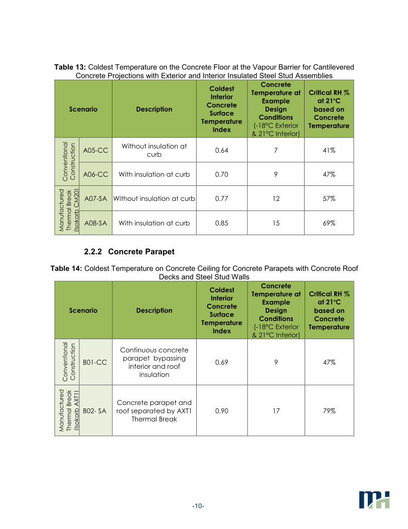
Table 13: Coldest Temperature on the Concrete Floor at the Vapour Barrier for Cantilevered Concrete Projections with Exterior and Interior Insulated Steel Stud Assemblies
Scenario Description
Coldest
Interior
Concrete
Surface
Temperature
Index
Concrete
Temperature at
Example
Design
Conditions
(-18°C Exterior
& 21°C Interior)
Critical RH %
at 21°C
based on
Concrete
Temperature
Co
nv
en
tio
na
l
Co
nst
ruc
tio
n
A05-CC Without insulation at
curb 0.64 7 41%
A06-CC With insulation at curb 0.70 9 47%
Ma
nu
fac
ture
d
The
rma
l B
rea
k
(Iso
ko
rb C
M20
)
A07-SA Without insulation at curb 0.77 12 57%
A08-SA With insulation at curb 0.85 15 69%
2.2.2 Concrete Parapet
Table 14: Coldest Temperature on Concrete Ceiling for Concrete Parapets with Concrete Roof Decks and Steel Stud Walls
Scenario Description
Coldest
Interior
Concrete
Surface
Temperature
Index
Concrete
Temperature at
Example
Design
Conditions
(-18°C Exterior
& 21°C Interior)
Critical RH %
at 21°C
based on
Concrete
Temperature
Co
nv
en
tio
na
l
Co
nst
ruc
tio
n
B01-CC
Continuous concrete
parapet bypassing
interior and roof
insulation
0.69 9 47%
Ma
nu
fac
ture
d
The
rma
l B
rea
k
(Iso
ko
rb A
XT1
)
B02- SA
Concrete parapet and
roof separated by AXT1
Thermal Break
0.90 17 79%

-11-
2.2.3 Steel to Steel Connection
Table 15: Coldest Temperature on Steel Beam at Vapour Barrier for Structural Steel Beam Connections to Concrete Floor Slabs
Scenario Description Temperature
Index
Beam
Temperature at
Example
Design
Conditions
(-18°C Exterior
& 21°C Interior)
Critical RH %
at 21°C
based on
Beam
Surface
Temperature
Co
nv
en
tio
na
l
Co
nst
ruc
tio
n
C01-CC Uninterrupted steel
beam 0.52 2 29%
The
rma
l Is
ola
tor
Pa
d
C02-TI
5 mm isolator pad,
stainless steel bolts 0.33 -5 17%
5 mm isolator pad,
steel bolts 0.32 -5 17%
5 mm pad, stainless
steel bolts, R-10
outboard of flanges
0.39 -3 20%
10 mm isolator pad,
stainless steel bolts 0.42 -2 21%
10 mm isolator pad,
steel bolts 0.41 -2 21%
19 mm isolator pad,
steel bolts 0.48 1 27%
25 mm isolator pad,
steel bolts 0.51 2 29%
Ma
nu
fac
ture
d
The
rma
l B
rea
k
(Iso
ko
rb S
22)
C03-SA
Steel beam
separated by Isokorb
S22 thermal break
0.79 13 61%

-12-
2.2.4 Steel to Concrete Connection
Table 16: Coldest Temperature on the Concrete Floor for Structural Steel Beam Connections to Concrete Floor Slabs
Scenario Description Temperature
Index
Concrete
Temperature at
Example
Design
Conditions
(-18°C Exterior
& 21°C Interior)
Critical RH %
at 21°C
based on
Concrete
Surface
Temperature
Co
nv
en
tio
na
l
Co
nst
ruc
tio
n
D01-CC Steel beam bypassing
exterior insulation 0.40 -2 21%
The
rma
l
Iso
lato
r P
ad
D02-TI
10mm Isolator pad
between steel beam
and concrete
0.54 3 31%
Ma
nu
fac
ture
d
The
rma
l B
rea
k
(Iso
ko
rb K
S1
4)
D03-SA
Isokorb KS14 thermal
break between steel
beam and concrete
0.84 15 70%
2.2.1 Poured-in Place Concrete Wall to Floor Slab
Table 17: Coldest Temperature on the Concrete Floor at the Vapour Barrier for Interior Insulated Concrete Walls
Scenario Description Temperature
Index
Concrete
Temperature at
Example
Design
Conditions
(-18°C Exterior
& 21°C Interior)
Critical RH %
at 21°C
based on
Concrete
Surface
Temperature
Co
nv
en
tio
na
l
Co
nst
ruc
tio
n
E01-CC
Continuous concrete
floor to wall
connection,
bypassing interior
insulation
0.57 4 33%
Ma
nu
fac
ture
d
The
rma
l B
rea
k
(Ru
the
rma
DF)
E02-SA
Concrete wall and
floor separated by
Rutherma DF Thermal
Break
0.70 9 47%

-13-
3. SUMMARY
The Schöck products evaluated in this study demonstrate effective solutions to minimize the impact of thermal bridging at common interface details. The Schöck solutions provide significant improvements in reducing the thermal transmittance and risk of condensation compared to current common practice.
Continuous concrete slab projections have very high linear transmittances. The Schöck Isokorb CM20 can reduce that heat loss by a large amount, but by how much depends on the detailing. For the scenario without insulation at the curb, there is a gap in the insulation between the Isokorb system and the exterior insulation, and the linear transmittance is reduced by over 50%. When there is insulation at the curb, the linear transmittance is reduced by almost 80%. This highlights the importance of a holistic approach for reducing thermal bridging and how a small amount of insulation can make a difference if the large thermal bridges are dealt with using products like the Isokorb system.
The concrete parapets can also result in a large amount of heat loss, especially in low-rise buildings. With the Schöck AXT1 system, the heat loss is reduced by over 85% compared to common practice. Moreover, the AXT1 system is likely cheaper and more effective to use the AXTI system than wrapping the entire parapet in insulation. The AXT1 system is more effective, and has lower linear transmittance than a fully insulated parapet tall parapet, because the geometric thermal bridge is eliminated with the AXT1 system. A geometric thermal bridge for a fully insulated parapet is a result of heat flowing to the parapet and increased surface area exposed to the exterior. A direct comparable parapet was not evaluated as part of this study but examples of fully insulated parapets are included in the Thermal Bridging Guide, which also includes construction cost comparisons. The following graphics illustrate the difference between a parapet with AXT1 and a fully insulated parapet. Note the clear wall assemblies are slightly different.
Figure 1. A parapet with the AXT1 system. The roof
insulation is carried to the exterior insulation at the same
level via the AXT1 system. The parapet is cold
(blue),indicating less heat flow and a more efficient
system.
Figure 2. A parapet with the insulation wrapped around the
parapet structure. The parapet is warm (green), indicating
more heat flow and a less efficient system.
Steel beams penetrating the envelope may be a concern with heat loss. However, a greater concern is often the risk of condensation at cold surfaces. For the evaluated scenarios, the isolator pads did not provide an effective solution. This is partially because of the assumed
-14-
large flanges on the beams that are required to support cantilevered beams. This detail results in less insulation around the beam and increased conductive area (fin effect) at the connection. The other reason is that the isolator pads provide little thermal resistance to overcome the increased conductive area created by the flanges at the connection. The heat flow is reduced by almost 50% using the Isokorb S22 system for the same assumptions as the isolator pads. Moreover, the risk of condensation is minimized with the Isokorb S22 system. The Isokorb S22 system is effective because the thermal break is much thicker, provides effective thermal resistance, and aligns with the exterior insulation around it.
With the steel beam to concrete floor connection, the isolator pads reduce the heat flow by almost 30% compared to over 90% for the Isokorb KS14 system. The risk of condensation is also greatly reduced with the Isokorb KS14 system. In comparison the benefit of the isolator pads is marginal. It is also important to recognize that the thermally broken steel beams appear to offer significant reductions in heat flow for balcony applications than the thermally broken cantilevered concrete solution (Isokorb CM20).
The interior insulated concrete wall at the floor slab interface is a major source of heat loss, on par with continuous concrete balconies. With the Schöck Rutherma DF, the thermal transmittance is reduced by over 60% compared to common construction. Other options to minimize thermal bridging at the floor slabs is to insulate outboard of the concrete structure and/or utilize precast concrete assemblies that are insulated at the floor slab. In comparison, these options are a larger deviation from this common construction practice than for the Rutherma DF system. The Rutherma DF system is a solution that has the potential to integrate into interior insulated poured-in-place concrete construction and make the insulation effective, which is not current practice for this type of construction.
Finally, readers should recognize that the Schöck products in this report were evaluated strictly in terms of thermal performance. There are other considerations that designers need to consider alongside thermal performance, such as structural requirements. Schöck has technical manuals that have been developed for these purposes.
Yours truly,
Morrison Hershfield Limited
Neil Norris, M.A.Sc. Patrick Roppel, P.Eng. Building Science Consultant Building Science Specialist

APPENDIX A: Material and Assembly Data Sheets

-A.1-
Detail A01-CC Exterior Insulated 3 5/8” x 1 5/8” Steel Stud (16” o.c.) Wall Assembly with Horizontal Z-girts (24” o.c.) Supporting Metal Cladding – Uninsulated Concrete Slab Intersection with Uninsulated Curb
1 Value selected from table 1, p. 26.1 of 2009 ASHRAE Handbook – Fundamentals depending on surface orientation
ID Component Thickness
Inches (mm)
Conductivity Btu·in / ft2·hr·oF (W/m K)
Nominal Resistance hr·ft2·oF/Btu
(m2K/W)
Density lb/ft3
(kg/m3)
Specific Heat
Btu/lb·oF (J/kg K)
1 Interior Film (right side)1 - - R-0.6 (0.11 RSI) to
R-0.9 (0.16 RSI) - -
2 Gypsum Board 1/2" (13) 1.1 (0.16) R-0.5 (0.08 RSI) 50 (800) 0.26 (1090)
3 3 5/8” x 1 5/8” Steel Studs with Top and Bottom Tracks
18 Gauge 430 (62) - 489 (7830) 0.12 (500)
4 Air Cavity 3 5/8” (92) - R-0.9 (0.16 RSI) 0.075 (1.2) 0.24 (1000)
5 Exterior Sheathing 1/2” (13) 1.1 (0.16) R-0.5 (0.09 RSI) 50 (800) 0.26 (1090)
6 Horizontal Z-Girt with 1 1/2” Flange 18 Gauge 430 (62) - 489 (7830) 0.12 (500)
7 Exterior Insulation 3” (76) - R-15 (2.64 RSI) 1.8 (28) 0.29 (1220)
8 Panel Clip 14 Gauge 430 (62) - 489 (7830) 0.12 (500)
9 Metal Cladding with ½” vented airspace incorporated into exterior heat transfer coefficient
10 Concrete Slab 8” (204) 12.5 (1.8) - 140 (2250) 0.20 (850)
11 Exterior Film (left side)1 - - R-0.2 (0.03 RSI) to
R-0.7 (0.12 RSI) - -
Balcony Stepdown Detail
-A.2-
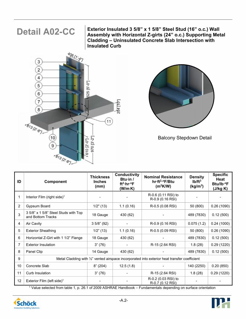
Detail A02-CC Exterior Insulated 3 5/8” x 1 5/8” Steel Stud (16” o.c.) Wall Assembly with Horizontal Z-girts (24” o.c.) Supporting Metal Cladding – Uninsulated Concrete Slab Intersection with Insulated Curb
1 Value selected from table 1, p. 26.1 of 2009 ASHRAE Handbook – Fundamentals depending on surface orientation
ID Component Thickness
Inches (mm)
Conductivity Btu·in / ft2·hr·oF (W/m K)
Nominal Resistance hr·ft2·oF/Btu
(m2K/W)
Density lb/ft3
(kg/m3)
Specific Heat
Btu/lb·oF (J/kg K)
1 Interior Film (right side)1 - - R-0.6 (0.11 RSI) to
R-0.9 (0.16 RSI) - -
2 Gypsum Board 1/2" (13) 1.1 (0.16) R-0.5 (0.08 RSI) 50 (800) 0.26 (1090)
3 3 5/8” x 1 5/8” Steel Studs with Top and Bottom Tracks
18 Gauge 430 (62) - 489 (7830) 0.12 (500)
4 Air Cavity 3 5/8” (92) - R-0.9 (0.16 RSI) 0.075 (1.2) 0.24 (1000)
5 Exterior Sheathing 1/2” (13) 1.1 (0.16) R-0.5 (0.09 RSI) 50 (800) 0.26 (1090)
6 Horizontal Z-Girt with 1 1/2” Flange 18 Gauge 430 (62) - 489 (7830) 0.12 (500)
7 Exterior Insulation 3” (76) - R-15 (2.64 RSI) 1.8 (28) 0.29 (1220)
8 Panel Clip 14 Gauge 430 (62) - 489 (7830) 0.12 (500)
9 Metal Cladding with ½” vented airspace incorporated into exterior heat transfer coefficient
10 Concrete Slab 8” (204) 12.5 (1.8) - 140 (2250) 0.20 (850)
11 Curb Insulation 3” (76) - R-15 (2.64 RSI) 1.8 (28) 0.29 (1220)
12 Exterior Film (left side)1 - - R-0.2 (0.03 RSI) to
R-0.7 (0.12 RSI) - -
Balcony Stepdown Detail

-A.3-
Detail A03-SA Exterior Insulated 3 5/8” x 1 5/8” Steel Stud (16” o.c.) Wall Assembly with Horizontal Z-girts (24” o.c.) Supporting Metal Cladding – Isokorb CM20 Thermally Broken Slab Projection with Uninsulated Curb
1 Value selected from table 1, p. 26.1 of 2009 ASHRAE Handbook – Fundamentals depending on surface orientation
ID Component Thickness
Inches (mm)
Conductivity Btu·in / ft2·hr·oF (W/m K)
Nominal Resistance hr·ft2·oF/Btu
(m2K/W)
Density lb/ft3
(kg/m3)
Specific Heat
Btu/lb·oF (J/kg K)
1 Interior Films (right side)1 - - R-0.6 (0.11 RSI) to
R-0.9 (0.16 RSI) - -
2 Gypsum Board 1/2" (13) 1.1 (0.16) R-0.5 (0.08 RSI) 50 (800) 0.26 (1090)
3 3 5/8” x 1 5/8” Steel Studs with Top and Bottom Tracks
18 Gauge 430 (62) - 489 (7830) 0.12 (500)
4 Air Cavity 3 5/8” (92) - R-0.9 (0.16 RSI) 0.075 (1.2) 0.24 (1000)
5 Exterior Sheathing 1/2” (13) 1.1 (0.16) R-0.5 (0.09 RSI) 50 (800) 0.26 (1090)
6 Horizontal Z-girts w/ 1 1/2" Flange 18 Gauge 430 (62) - 489 (7830) 0.12 (500)
7 Exterior Insulation 3” (76) - R-15 (2.64 RSI) 1.8 (28) 0.29 (1220)
8 Metal Cladding with ½” vented airspace incorporated into exterior heat transfer coefficient
9 Concrete Slab 8” (203) 12 (1.8) - 140 (2250) 0.20 (850)
10 Stainless Steel Rebar - 118 (17) - 500 (8000) 0.12 (500)
11 HDPE Plastic Sleeve - 1.7 (0.25) - 59 (950) 0.48 (2000)
UHPC Concrete Mix - 5.5 (0.80) - 140 (2250) 0.20 (850)
12 Polystyrene Hard Foam Insulation 3” (76) 0.217 (0.031) R-14.7 (2.58 RSI) 66 (1060) 0.35 (1500)
13 Cement Board 1/2” (13) 1.7 (0.25) - 72 (1150) 0.20 (850)
14 Exterior Film (left side)1 - - R-0.2 (0.03 RSI) to
R-0.7 (0.12 RSI) - -
Thermally Broken Slab Detail (Isokorb CM20)

-A.4-
Detail A04-SA Exterior Insulated 3 5/8” x 1 5/8” Steel Stud (16” o.c.) Wall Assembly with Horizontal Z-girts (24” o.c.) Supporting Metal Cladding – Isokorb CM20 Thermally Broken Slab Projection with Insulated Curb
1 Value selected from table 1, p. 26.1 of 2009 ASHRAE Handbook – Fundamentals depending on surface orientation
ID Component Thickness
Inches (mm)
Conductivity Btu·in / ft2·hr·oF (W/m K)
Nominal Resistance hr·ft2·oF/Btu
(m2K/W)
Density lb/ft3
(kg/m3)
Specific Heat
Btu/lb·oF (J/kg K)
1 Interior Films (right side)1 - - R-0.6 (0.11 RSI) to
R-0.9 (0.16 RSI) - -
2 Gypsum Board 1/2" (13) 1.1 (0.16) R-0.5 (0.08 RSI) 50 (800) 0.26 (1090)
3 3 5/8” x 1 5/8” Steel Studs with Top and Bottom Tracks
18 Gauge 430 (62) - 489 (7830) 0.12 (500)
4 Air Cavity 3 5/8” (92) - R-0.9 (0.16 RSI) 0.075 (1.2) 0.24 (1000)
5 Exterior Sheathing 1/2” (13) 1.1 (0.16) R-0.5 (0.09 RSI) 50 (800) 0.26 (1090)
6 Horizontal Z-girts w/ 1 1/2" Flange 18 Gauge 430 (62) - 489 (7830) 0.12 (500)
7 Exterior Insulation 3” (76) - R-15 (2.64 RSI) 1.8 (28) 0.29 (1220)
8 Metal Cladding with ½” vented airspace incorporated into exterior heat transfer coefficient
9 Concrete Slab 8” (203) 12 (1.8) - 140 (2250) 0.20 (850)
10 Stainless Steel Rebar - 118 (17) - 500 (8000) 0.12 (500)
11 HDPE Plastic Sleeve - 1.7 (0.25) - 59 (950) 0.48 (2000)
UHPC Concrete Mix - 5.5 (0.80) - 140 (2250) 0.20 (850)
12 Polystyrene Hard Foam Insulation 3 1/8” (80) 0.217 (0.031) R-14.7 (2.58 RSI) 66 (1060) 0.35 (1500)
13 Cement Board 1/2” (13) 1.7 (0.25) - 72 (1150) 0.20 (850)
14 Curb Insulation 3” (76) - R-15 (2.64 RSI) 1.8 (28) 0.29 (1220)
15 Exterior Film (left side)1 - - R-0.2 (0.03 RSI) to
R-0.7 (0.12 RSI) - -
Thermally Broken Slab Detail (Isokorb CM20)

-A.5-
Detail A05-CC Exterior and Interior Insulated 3 5/8” x 1 5/8” Steel Stud (16” o.c.) Wall Assembly with Horizontal Z-girts (24” o.c.) Supporting Metal Cladding – Uninsulated Concrete Slab Intersection with Uninsulated Curb
1 Value selected from table 1, p. 26.1 of 2009 ASHRAE Handbook – Fundamentals depending on surface orientation
ID Component Thickness
Inches (mm)
Conductivity Btu·in / ft2·hr·oF (W/m K)
Nominal Resistance hr·ft2·oF/Btu
(m2K/W)
Density lb/ft3
(kg/m3)
Specific Heat
Btu/lb·oF (J/kg K)
1 Interior Film (right side)1 - - R-0.6 (0.11 RSI) to
R-0.9 (0.16 RSI) - -
2 Gypsum Board 1/2" (13) 1.1 (0.16) R-0.5 (0.08 RSI) 50 (800) 0.26 (1090)
3 3 5/8” x 1 5/8” Steel Studs with Top and Bottom Tracks
18 Gauge 430 (62) - 489 (7830) 0.12 (500)
4 Fiberglass Batt Insulation 3 5/8” (92) 0.29 (0.044) R-12 (2.11 RSI) 0.9 (14) 0.17 (710)
5 Exterior Sheathing 1/2” (13) 1.1 (0.16) R-0.5 (0.09 RSI) 50 (800) 0.26 (1090)
6 Horizontal Z-Girt with 1 1/2” Flange 18 Gauge 430 (62) - 489 (7830) 0.12 (500)
7 Exterior Insulation 3” (76) - R-15 (2.64 RSI) 1.8 (28) 0.29 (1220)
8 Panel Clip 14 Gauge 430 (62) - 489 (7830) 0.12 (500)
9 Metal Cladding with ½” vented airspace incorporated into exterior heat transfer coefficient
10 Concrete Slab 8” (204) 12.5 (1.8) - 140 (2250) 0.20 (850)
11 Exterior Film (left side)1 - - R-0.2 (0.03 RSI) to
R-0.7 (0.12 RSI) - -
Balcony Stepdown Detail

-A.6-
Detail A06-CC Exterior and Interior Insulated 3 5/8” x 1 5/8” Steel Stud (16” o.c.) Wall Assembly with Horizontal Z-girts (24” o.c.) Supporting Metal Cladding – Uninsulated Concrete Slab Intersection with Insulated Curb
1 Value selected from table 1, p. 26.1 of 2009 ASHRAE Handbook – Fundamentals depending on surface orientation
ID Component Thickness
Inches (mm)
Conductivity Btu·in / ft2·hr·oF (W/m K)
Nominal Resistance hr·ft2·oF/Btu
(m2K/W)
Density lb/ft3
(kg/m3)
Specific Heat
Btu/lb·oF (J/kg K)
1 Interior Film (right side)1 - - R-0.6 (0.11 RSI) to
R-0.9 (0.16 RSI) - -
2 Gypsum Board 1/2" (13) 1.1 (0.16) R-0.5 (0.08 RSI) 50 (800) 0.26 (1090)
3 3 5/8” x 1 5/8” Steel Studs with Top and Bottom Tracks
18 Gauge 430 (62) - 489 (7830) 0.12 (500)
4 Fiberglass Batt Insulation 3 5/8” (92) 0.29 (0.044) R-12.0 (2.11 RSI) 0.9 (14) 0.17 (710)
5 Exterior Sheathing 1/2” (13) 1.1 (0.16) R-0.5 (0.09 RSI) 50 (800) 0.26 (1090)
6 Horizontal Z-Girt with 1 1/2” Flange 18 Gauge 430 (62) - 489 (7830) 0.12 (500)
7 Exterior Insulation 3” (76) - R-15 (2.64 RSI) 1.8 (28) 0.29 (1220)
8 Panel Clip 14 Gauge 430 (62) - 489 (7830) 0.12 (500)
9 Metal Cladding with ½” vented airspace incorporated into exterior heat transfer coefficient
10 Concrete Slab 8” (204) 12.5 (1.8) - 140 (2250) 0.20 (850)
11 Curb Insulation - - R-15 (2.64 RSI) 1.8 (28) 0.29 (1220)
12 Exterior Film (left side)1 - - R-0.2 (0.03 RSI) to
R-0.7 (0.12 RSI) - -
Balcony Stepdown Detail

-A.7-
Detail A07-SA Exterior and Interior Insulated 3 5/8” x 1 5/8” Steel Stud (16” o.c.) Wall Assembly with Horizontal Z-girts (24” o.c.) Supporting Metal Cladding – Isokorb CM20 Thermally Broken Slab Projection with Uninsulated Curb
1 Value selected from table 1, p. 26.1 of 2009 ASHRAE Handbook – Fundamentals depending on surface orientation
ID Component Thickness
Inches (mm)
Conductivity Btu·in / ft2·hr·oF (W/m K)
Nominal Resistance hr·ft2·oF/Btu
(m2K/W)
Density lb/ft3
(kg/m3)
Specific Heat
Btu/lb·oF (J/kg K)
1 Interior Films (right side)1 - - R-0.6 (0.11 RSI) to
R-0.9 (0.16 RSI) - -
2 Gypsum Board 1/2" (13) 1.1 (0.16) R-0.5 (0.08 RSI) 50 (800) 0.26 (1090)
3 3 5/8” x 1 5/8” Steel Studs with Top and Bottom Tracks
18 Gauge 430 (62) - 489 (7830) 0.12 (500)
4 Fibreglass Batt Insulation 3 5/8” (92) 0.29 (0.044) R-12.0 (2.11 RSI) 0.9 (14) 0.17 (710)
5 Exterior Sheathing 1/2” (13) 1.1 (0.16) R-0.5 (0.09 RSI) 50 (800) 0.26 (1090)
6 Horizontal Z-girts w/ 1 1/2" Flange 18 Gauge 430 (62) - 489 (7830) 0.12 (500)
7 Exterior Insulation 3” (76) - R-15 (2.64 RSI) 1.8 (28) 0.29 (1220)
8 Metal Cladding with ½” vented airspace incorporated into exterior heat transfer coefficient
9 Concrete Slab 8” (203) 12 (1.8) - 140 (2250) 0.20 (850)
10 Stainless Steel Rebar - 118 (17) - 500 (8000) 0.12 (500)
11 HDPE Plastic Sleeve - 1.7 (0.25) - 59 (950) 0.48 (2000)
UHPC Concrete Mix - 5.5 (0.80) - 140 (2250) 0.20 (850)
12 Polystyrene Hard Foam Insulation 3 1/8” (80) 0.2 (0.031) R-14.7 (2.58 RSI) 66 (1060) 0.35 (1500)
13 Cement Board 1/2” (13) 1.7 (0.25) - 72 (1150) 0.20 (850)
14 Exterior Film (left side)1 - - R-0.2 (0.03 RSI) to
R-0.7 (0.12 RSI) - -
Thermally Broken Slab Detail (Isokorb CM20)

-A.8-
Detail A08-SA Exterior and Interior Insulated 3 5/8” x 1 5/8” Steel Stud (16” o.c.) Wall Assembly with Horizontal Z-girts (24” o.c.) Supporting Metal Cladding – Isokorb CM20 Thermally Broken Slab Projection with Insulated Curb
1 Value selected from table 1, p. 26.1 of 2009 ASHRAE Handbook – Fundamentals depending on surface orientation
ID Component Thickness
Inches (mm)
Conductivity Btu·in / ft2·hr·oF (W/m K)
Nominal Resistance hr·ft2·oF/Btu
(m2K/W)
Density lb/ft3
(kg/m3)
Specific Heat
Btu/lb·oF (J/kg K)
1 Interior Films (right side)1 - - R-0.6 (0.11 RSI) to
R-0.9 (0.16 RSI) - -
2 Gypsum Board 1/2" (13) 1.1 (0.16) R-0.5 (0.08 RSI) 50 (800) 0.26 (1090)
3 3 5/8” x 1 5/8” Steel Studs with Top and Bottom Tracks
18 Gauge 430 (62) - 489 (7830) 0.12 (500)
4 Fibreglass Batt Insulation 3 5/8” (92) 0.29 (0.044) R-12.0 (2.11 RSI) 0.9 (14) 0.17 (710)
5 Exterior Sheathing 1/2” (13) 1.1 (0.16) R-0.5 (0.09 RSI) 50 (800) 0.26 (1090)
6 Horizontal Z-girts w/ 1 1/2" Flange 18 Gauge 430 (62) - 489 (7830) 0.12 (500)
7 Exterior Insulation 3” (76) - R-15 (2.64 RSI) 1.8 (28) 0.29 (1220)
8 Metal Cladding with ½” vented airspace incorporated into exterior heat transfer coefficient
9 Concrete Slab 8” (203) 12 (1.8) - 140 (2250) 0.20 (850)
10 Stainless Steel Rebar - 118 (17) - 500 (8000) 0.12 (500)
11 HDPE Plastic Sleeve - 1.7 (0.25) - 59 (950) 0.48 (2000)
UHPC Concrete Mix - 5.5 (0.80) - 140 (2250) 0.20 (850)
12 Polystyrene Hard Foam Insulation 3 1/8” (80) 0.217 (0.031) R-14.7 (2.58 RSI) 66 (1060) 0.35 (1500)
13 Cement Board 1/2” (13) 1.7 (0.25) - 72 (1150) 0.20 (850)
14 Curb Insulation 3” (76) - R-15 (2.64 RSI) 1.8 (28) 0.29 (1220)
15 Exterior Film (left side)1 - - R-0.2 (0.03 RSI) to
R-0.7 (0.12 RSI) - -
Thermally Broken Slab Detail (Isokorb CM20)
-A.9-
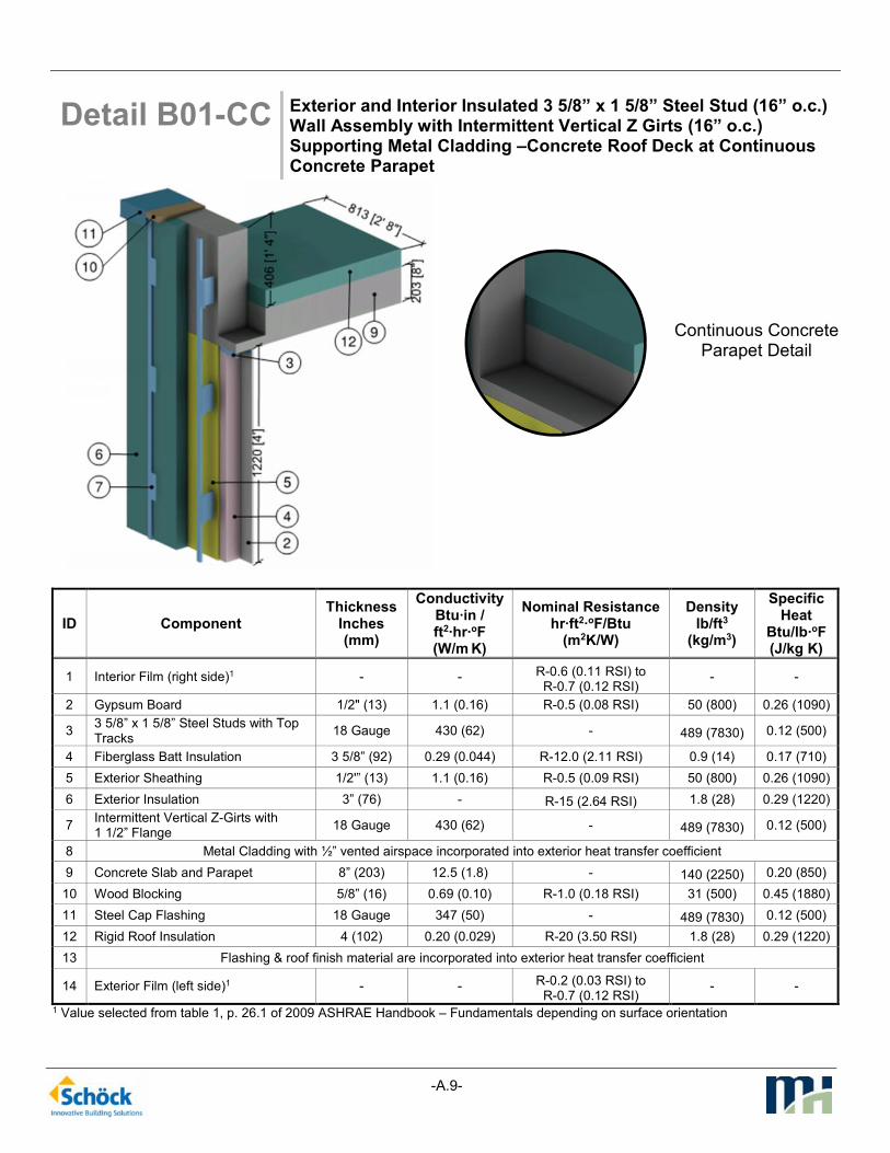
Detail B01-CC Exterior and Interior Insulated 3 5/8” x 1 5/8” Steel Stud (16” o.c.) Wall Assembly with Intermittent Vertical Z Girts (16” o.c.) Supporting Metal Cladding –Concrete Roof Deck at Continuous Concrete Parapet
1 Value selected from table 1, p. 26.1 of 2009 ASHRAE Handbook – Fundamentals depending on surface orientation
ID Component Thickness
Inches (mm)
Conductivity Btu·in / ft2·hr·oF (W/m K)
Nominal Resistance hr·ft2·oF/Btu
(m2K/W)
Density lb/ft3
(kg/m3)
Specific Heat
Btu/lb·oF (J/kg K)
1 Interior Film (right side)1 - - R-0.6 (0.11 RSI) to R-0.7 (0.12 RSI)
- -
2 Gypsum Board 1/2" (13) 1.1 (0.16) R-0.5 (0.08 RSI) 50 (800) 0.26 (1090)
3 3 5/8” x 1 5/8” Steel Studs with Top Tracks
18 Gauge 430 (62) - 489 (7830) 0.12 (500)
4 Fiberglass Batt Insulation 3 5/8” (92) 0.29 (0.044) R-12.0 (2.11 RSI) 0.9 (14) 0.17 (710)
5 Exterior Sheathing 1/2'” (13) 1.1 (0.16) R-0.5 (0.09 RSI) 50 (800) 0.26 (1090)
6 Exterior Insulation 3” (76) - R-15 (2.64 RSI) 1.8 (28) 0.29 (1220)
7 Intermittent Vertical Z-Girts with 1 1/2” Flange
18 Gauge 430 (62) - 489 (7830) 0.12 (500)
8 Metal Cladding with ½” vented airspace incorporated into exterior heat transfer coefficient
9 Concrete Slab and Parapet 8” (203) 12.5 (1.8) - 140 (2250) 0.20 (850)
10 Wood Blocking 5/8” (16) 0.69 (0.10) R-1.0 (0.18 RSI) 31 (500) 0.45 (1880)
11 Steel Cap Flashing 18 Gauge 347 (50) - 489 (7830) 0.12 (500)
12 Rigid Roof Insulation 4 (102) 0.20 (0.029) R-20 (3.50 RSI) 1.8 (28) 0.29 (1220)
13 Flashing & roof finish material are incorporated into exterior heat transfer coefficient
14 Exterior Film (left side)1 - - R-0.2 (0.03 RSI) to R-0.7 (0.12 RSI)
- -
Continuous Concrete Parapet Detail

-A.10-
Detail B02-SA Exterior and Interior Insulated 3 5/8” x 1 5/8” Steel Stud (16” o.c.) Wall Assembly with Intermittent Vertical Z Girts (16” o.c.) Supporting Metal Cladding –Concrete Roof Deck at Isokorb AXT1 Thermally Broken Concrete Parapet
1 Value selected from table 1, p. 26.1 of 2009 ASHRAE Handbook – Fundamentals depending on surface orientation
ID Component Thickness
Inches (mm)
Conductivity Btu·in / ft2·hr·oF (W/m K)
Nominal Resistance hr·ft2·oF/Btu
(m2K/W)
Density lb/ft3
(kg/m3)
Specific Heat
Btu/lb·oF (J/kg K)
1 Interior Film (right side)1 - - R-0.6 (0.11 RSI) to R-0.7 (0.12 RSI)
- -
2 Gypsum Board 1/2" (13) 1.1 (0.16) R-0.5 (0.08 RSI) 50 (800) 0.26 (1090)
3 3 5/8” x 1 5/8” Steel Studs with Top Tracks
18 Gauge 430 (62) - 489 (7830) 0.12 (500)
4 Fiberglass Batt Insulation 3 5/8” (92) 0.29 (0.044) R-12.0 (2.11 RSI) 0.9 (14) 0.17 (710)
5 Exterior Sheathing 1/2'” (13) 1.1 (0.16) R-0.5 (0.09 RSI) 50 (800) 0.26 (1090)
6 Exterior Insulation 3” (76) - R-15 (2.64 RSI) 1.8 (28) 0.29 (1220)
7 Intermittent Vertical Z-Girts with 1 1/2” Flange
18 Gauge 430 (62) - 489 (7830) 0.12 (500)
8 Metal Cladding with ½” vented airspace incorporated into exterior heat transfer coefficient
9 Concrete Slab and Parapet 8” (203) 12.5 (1.8) - 140 (2250) 0.20 (850)
10 Stainless Steel Rebar - 118 (17) - 500 (8000) 0.12 (500)
11 Polystyrene Hard Foam Insulation 4 3/4” (120) 0.217 (0.031) R-22.0 (3.87 RSI) 66 (1060) 0.35 (1500)
12 Wood Blocking 5/8” (16) 0.69 (0.10) R-1.0 (0.18 RSI) 31 (500) 0.45 (1880)
13 Steel Cap Flashing 18 Gauge 347 (50) - 489 (7830) 0.12 (500)
14 Rigid Roof Insulation 4 (102) 0.20 (0.029) R-20 (3.50 RSI) 1.8 (28) 0.29 (1220)
15 Flashing & roof finish material are incorporated into exterior heat transfer coefficient
16 Exterior Film (left side)1 - - R-0.2 (0.03 RSI) to R-0.7 (0.12 RSI)
- -
Thermally Broken Parapet Detail (Isokorb AXT1)

-A.11-
Detail C01-CC Exterior and Interior Insulated 3 5/8” x 1 5/8” Steel Stud (16” o.c.) Wall Assembly with Horizontal Z-girts (24” o.c.) Supporting Metal Cladding – Structural Steel Floor Intersection with Uninterrupted Beam
1 Value selected from table 1, p. 26.1 of 2009 ASHRAE Handbook – Fundamentals depending on surface orientation
ID Component Thickness
Inches (mm)
Conductivity Btu·in / ft2·hr·oF (W/m K)
Nominal Resistance hr·ft2·oF/Btu
(m2K/W)
Density lb/ft3
(kg/m3)
Specific Heat
Btu/lb·oF (J/kg K)
1 Interior Film (right side)1 - - R-0.6 (0.11 RSI) to
R-0.9 (0.16 RSI) - -
2 Gypsum Board 1/2" (13) 1.1 (0.16) R-0.5 (0.08 RSI) 50 (800) 0.26 (1090)
3 3 5/8” x 1 5/8” Steel Studs with Top and Bottom Tracks
18 Gauge 430 (62) - 489 (7830) 0.12 (500)
4 Fibreglass Batt Insulation 3 5/8” (92) 0.29 (0.044) R-12.0 (2.11 RSI) 0.9 (14) 0.17 (710)
5 Exterior Sheathing 1/2” (13) 1.1 (0.16) R-0.5 (0.09 RSI) 50 (800) 0.26 (1090)
6 Horizontal Z-girts with 1 ½” Flange 18 Gauge 430 (62) - 489 (7830) 0.12 (500)
7 Exterior Insulation 3” (76) - R-15 (2.64 RSI) 1.8 (28) 0.29 (1220)
8 Metal Cladding with ½” vented airspace incorporated into exterior heat transfer coefficient
9 Steel Through Beam W14x26 (W360x39)
- 347 (50) - 489 (7830) 0.12 (500)
10 Steel Deck 1/16” (1.6) 347 (50) - 489 (7830) 0.12 (500)
11 Concrete Topping 6” (152) 6.3 (0.9) - 120 (1920) 0.20 (850)
12 Exterior Film (left side)1 - - R-0.7 (0.12 RSI) - -

-A.12-
Detail C02-TI Exterior and Interior Insulated 3 5/8” x 1 5/8” Steel Stud (16” o.c.) Wall Assembly with Horizontal Z-girts (24” o.c.) Supporting Metal Cladding – Structural Steel Floor Intersection with Isolator Pad
1 Value selected from table 1, p. 26.1 of 2009 ASHRAE Handbook – Fundamentals depending on surface orientation
ID Component Thickness
Inches (mm)
Conductivity Btu·in / ft2·hr·oF (W/m K)
Nominal Resistance hr·ft2·oF/Btu
(m2K/W)
Density lb/ft3
(kg/m3)
Specific Heat
Btu/lb·oF (J/kg K)
1 Interior Film (right side)1 - - R-0.6 (0.11 RSI) to
R-0.9 (0.16 RSI) - -
2 Gypsum Board 1/2" (13) 1.1 (0.16) R-0.5 (0.08 RSI) 50 (800) 0.26 (1090)
3 3 5/8” x 1 5/8” Steel Studs with Top and Bottom Tracks
18 Gauge 430 (62) - 489 (7830) 0.12 (500)
4 Fibreglass Batt Insulation 3 5/8” (92) 0.29 (0.044) R-12.0 (2.11 RSI) 0.9 (14) 0.17 (710)
5 Exterior Sheathing 1/2” (13) 1.1 (0.16) R-0.5 (0.09 RSI) 50 (800) 0.26 (1090)
6 Horizontal Z-girts with 1 ½” Flange 18 Gauge 430 (62) - 489 (7830) 0.12 (500)
7 Exterior Insulation 3” (76) - R-15 (2.64 RSI) 1.8 (28) 0.29 (1220)
8 Metal Cladding with ½” vented airspace incorporated into exterior heat transfer coefficient
9 Steel Beam W14x26 (W360x39) - 347 (50) - 489 (7830) 0.12 (500)
10 Steel Bearing Plates 1 3/16” (30) 347 (50) - 489 (7830) 0.12 (500)
11 Steel Deck 1/16” (1.6) 347 (50) - 489 (7830) 0.12 (500)
12 Concrete Topping 6” (152) 6.3 (0.9) - 120 (1920) 0.20 (850)
13 Steel or Stainless Steel Bolts - 347 (50) to
118 (17) - 500 (8000) 0.12 (500)
14 Polymer Thermal Isolator Pad 3/16”(5) to
1” (25) 1.7 (0.25)
R0.1 (0.02 RSI) to R-0.6 (0.10 RSI)
137 (2200) 0.31 (1300)
15 Exterior Film (left side)1 - - R-0.7 (0.12 RSI) - -

-A.13-
Detail C03-SA Exterior and Interior Insulated 3 5/8” x 1 5/8” Steel Stud (16” o.c.) Wall Assembly with Horizontal Z-girts (24” o.c.) Supporting Metal Cladding – Structural Steel Floor Intersection with Isokorb S22 Thermally Broken Beam
1 Value selected from table 1, p. 26.1 of 2009 ASHRAE Handbook – Fundamentals depending on surface orientation
ID Component Thickness
Inches (mm)
Conductivity Btu·in / ft2·hr·oF (W/m K)
Nominal Resistance hr·ft2·oF/Btu
(m2K/W)
Density lb/ft3
(kg/m3)
Specific Heat
Btu/lb·oF (J/kg K)
1 Interior Film (right side)1 - - R-0.6 (0.11 RSI) to
R-0.9 (0.16 RSI) - -
2 Gypsum Board 1/2" (13) 1.1 (0.16) R-0.5 (0.08 RSI) 50 (800) 0.26 (1090)
3 3 5/8” x 1 5/8” Steel Studs with Top and Bottom Tracks
18 Gauge 430 (62) - 489 (7830) 0.12 (500)
4 Fibreglass Batt Insulation 3 5/8” (92) 0.29 (0.044) R-12.0 (2.11 RSI) 0.9 (14) 0.17 (710)
5 Exterior Sheathing 1/2” (13) 1.1 (0.16) R-0.5 (0.09 RSI) 50 (800) 0.26 (1090)
6 Horizontal Z-girts with 1 ½” Flange 18 Gauge 430 (62) - 489 (7830) 0.12 (500)
7 Exterior Insulation 3” (76) - R-15 (2.64 RSI) 1.8 (28) 0.29 (1220)
8 Metal Cladding with ½” vented airspace incorporated into exterior heat transfer coefficient
9 Steel Beam W14x26 (W360x39) - 347 (50) - 489 (7830) 0.12 (500)
10 Steel Bearing Plates 1 3/16” (30) 347 (50) - 489 (7830) 0.12 (500)
11 Steel Deck 1/16” (1.6) 347 (50) - 489 (7830) 0.12 (500)
12 Concrete Topping 6” (152) 6.3 (0.9) - 120 (1920) 0.20 (850)
Isokorb S22 Thermal Break
13 Stainless Steel Bolts, Plates and HSS
- 118 (17) - 500 (8000) 0.12 (500)
14 Polystyrene Hard Foam Insulation 3 1/8” (80) 0.217 (0.031) R-14.5 (2.6 RSI) 66 (1060) 0.35 (1500)
15 Exterior Film (left side)1 - - R-0.7 (0.12 RSI) - -

-A.14-
Detail D01-CC Exterior Insulated 3 5/8” x 1 5/8” Steel Stud (16” o.c.) Wall Assembly with Intermittent Vertical Z-girts (16” o.c.) Supporting Metal Cladding – Concrete Floor to Steel Beam Connection
1 Value selected from table 1, p. 26.1 of 2009 ASHRAE Handbook – Fundamentals depending on surface orientation
ID Component Thickness
Inches (mm)
Conductivity Btu·in / ft2·hr·oF (W/m K)
Nominal Resistance hr·ft2·oF/Btu
(m2K/W)
Density lb/ft3
(kg/m3)
Specific Heat
Btu/lb·oF (J/kg K)
1 Interior Film (right side)1 - - R-0.6 (0.11 RSI) to
R-0.9 (0.16 RSI) - -
2 Gypsum Board 1/2" (13) 1.1 (0.16) R-0.5 (0.08 RSI) 50 (800) 0.26 (1090)
3 3 5/8” x 1 5/8” Steel Studs with Top and Bottom Tracks
18 Gauge 430 (62) - 489 (7830) 0.12 (500)
4 Air Cavity 3 5/8” (92) - R-0.9 (0.16 RSI) 0.075 (1.2) 0.24 (1000)
5 Exterior Sheathing 1/2” (13) 1.1 (0.16) R-0.5 (0.09 RSI) 50 (800) 0.26 (1090)
6 Intermittent Vertical Z-Girts with 1 1/2” Flange
18 Gauge 430 (62) - 489 (7830) 0.12 (500)
7 Exterior Insulation 3” (76) - R-15 (2.64 RSI) 1.8 (28) 0.29 (1220)
8 Metal Cladding with ½” vented airspace incorporated into exterior heat transfer coefficient
9 Concrete Slab 8 5/8” (220) 12.5 (1.8) - 140 (2250) 0.20 (850)
10 Steel Beam W8x18 (W200x27) - 347 (50) - 489 (7830) 0.12 (500)
11 Steel Bearing Plates 3/4” (20) 347 (50) - 489 (7830) 0.12 (500)
12 Steel Bolts and Rebar - 347 (50) - 489 (7830) 0.12 (500)
13 Stainless Steel Anchors - 118 (17) - 500 (8000) 0.12 (500)
14 Exterior Film (left side)1 - - R-0.2 (0.03 RSI) to
R-0.7 (0.12 RSI) - -

-A.15-
Detail D02-TI Exterior Insulated 3 5/8” x 1 5/8” Steel Stud (16” o.c.) Wall Assembly with Intermittent Vertical Z-girts (16” o.c.) Supporting Metal Cladding – Concrete Floor to Steel Beam with a Thermal Isolator Pad Connection
1 Value selected from table 1, p. 26.1 of 2009 ASHRAE Handbook – Fundamentals depending on surface orientation
ID Component Thickness
Inches (mm)
Conductivity Btu·in / ft2·hr·oF (W/m K)
Nominal Resistance hr·ft2·oF/Btu
(m2K/W)
Density lb/ft3
(kg/m3)
Specific Heat
Btu/lb·oF (J/kg K)
1 Interior Film (right side)1 - - R-0.6 (0.11 RSI) to
R-0.9 (0.16 RSI) - -
2 Gypsum Board 1/2" (13) 1.1 (0.16) R-0.5 (0.08 RSI) 50 (800) 0.26 (1090)
3 3 5/8” x 1 5/8” Steel Studs with Top and Bottom Tracks
18 Gauge 430 (62) - 489 (7830) 0.12 (500)
4 Air Cavity 3 5/8” (92) - R-0.9 (0.16 RSI) 0.075 (1.2) 0.24 (1000)
5 Exterior Sheathing 1/2” (13) 1.1 (0.16) R-0.5 (0.09 RSI) 50 (800) 0.26 (1090)
6 Intermittent Vertical Z-Girts with 1 1/2” Flange
18 Gauge 430 (62) - 489 (7830) 0.12 (500)
7 Exterior Insulation 3” (76) - R-15 (2.64 RSI) 1.8 (28) 0.29 (1220)
8 Metal Cladding with ½” vented airspace incorporated into exterior heat transfer coefficient
9 Concrete Slab 8 5/8” (220) 12.5 (1.8) - 140 (2250) 0.20 (850)
10 Steel Beam W8x18 (W200x27) - 347 (50) - 489 (7830) 0.12 (500)
11 Steel Bearing Plates 3/4” (20) 347 (50) - 489 (7830) 0.12 (500)
12 Steel Bolts and Rebar - 347 (50) - 489 (7830) 0.12 (500)
13 Stainless Steel Anchors - 118 (17) - 500 (8000) 0.12 (500)
14 Polymer Thermal Isolator Pad 3/8” (10) 1.7 (0.25) R-0.23 (0.04 RSI) 137 (2200) 0.31 (1300)
15 Exterior Film (left side)1 - - R-0.2 (0.03 RSI) to
R-0.7 (0.12 RSI) - -

-A.16-
Detail D03-SA Exterior Insulated 3 5/8” x 1 5/8” Steel Stud (16” o.c.) Wall Assembly with Intermittent Vertical Z-girts (16” o.c.) Supporting Metal Cladding – Concrete Floor to Steel Beam with Isokorb Ks14 Connection
1 Value selected from table 1, p. 26.1 of 2009 ASHRAE Handbook – Fundamentals depending on surface orientation
ID Component Thickness
Inches (mm)
Conductivity Btu·in / ft2·hr·oF (W/m K)
Nominal Resistance hr·ft2·oF/Btu
(m2K/W)
Density lb/ft3
(kg/m3)
Specific Heat
Btu/lb·oF (J/kg K)
1 Interior Film (right side)1 - - R-0.6 (0.11 RSI) to
R-0.9 (0.16 RSI) - -
2 Gypsum Board 1/2" (13) 1.1 (0.16) R-0.5 (0.08 RSI) 50 (800) 0.26 (1090)
3 3 5/8” x 1 5/8” Steel Studs with Top and Bottom Tracks
18 Gauge 430 (62) - 489 (7830) 0.12 (500)
4 Air Cavity 3 5/8” (92) - R-0.9 (0.16 RSI) 0.075 (1.2) 0.24 (1000)
5 Exterior Sheathing 1/2” (13) 1.1 (0.16) R-0.5 (0.09 RSI) 50 (800) 0.26 (1090)
6 Intermittent Vertical Z-Girts with 1 1/2” Flange
18 Gauge 430 (62) - 489 (7830) 0.12 (500)
7 Exterior Insulation 3” (76) - R-15 (2.64 RSI) 1.8 (28) 0.29 (1220)
8 Metal Cladding with ½” vented airspace incorporated into exterior heat transfer coefficient
9 Concrete Slab 8 5/8” (220) 12.5 (1.8) - 140 (2250) 0.20 (850)
10 Steel Beam W8x18 (W200x27) - 347 (50) - 489 (7830) 0.12 (500)
11 Steel Bearing Plate with Butt Stop 3/4” (20) 347 (50) - 489 (7830) 0.12 (500)
Isokorb KS14 Thermal Break
12 Stainless Steel Reinforcement - 118 (17) - 500 (8000) 0.12 (500)
13 Polystyrene Hard Foam Insulation 3 1/8” (80) 0.217 (0.031) R-14.5 (2.6 RSI) 66 (1060) 0.35 (1500)
14 Exterior Film (left side)1 - - R-0.2 (0.03 RSI)
to R-0.7 (0.12 RSI) - -

-A.17-
Detail E01-CC Interior Insulated Concrete Mass Wall with 1 5/8” Steel Studs (16” o.c.) Supporting Interior Finish – Continuous Concrete Floor Slab Intersection
1 Value selected from table 1, p. 26.1 of 2009 ASHRAE Handbook – Fundamentals depending on surface orientation
ID Component Thickness
Inches (mm)
Conductivity Btu·in / ft2·hr·oF (W/m K)
Nominal Resistance hr·ft2·oF/Btu
(m2K/W)
Density lb/ft3
(kg/m3)
Specific Heat
Btu/lb·oF (J/kg K)
1 Interior Film (right side)1 - - R-0.6 (0.11 RSI) to
R-0.9 (0.16 RSI) - -
2 Gypsum Board 1/2" (13) 1.1 (0.16) R-0.5 (0.08 RSI) 50 (800) 0.26 (1090)
3 1 5/8” x 1 5/8” Steel Studs with Top and Bottom Tracks
18 Gauge 430 (62) - 489 (7830) 0.12 (500)
4 Air in Stud Cavity 1 5/8” (41) - R-0.9 (0.16 RSI) 0.075 (1.2) 0.24 (1000)
5 Continuous Insulation 2 1/2" (64) - R-10.0 (1.76 RSI) 1.8 (28) 0.29 (1220)
6 Concrete Wall 8” (203) 12.5 (1.8) R-0.64 (0.11 RSI) 140 (2250) 0.20 (850)
7 Concrete Slab 8” (203) 12.5 (1.8) - 140 (2250) 0.20 (850)
8 Exterior Film (left side)1 - - R-0.2 (0.03 RSI) - -
Continuous Concrete Slab Detail

-A.18-
Detail E02-SA Interior Insulated Concrete Mass Wall with 1 5/8” Steel Studs (16” o.c.) Supporting Interior Finish – Isokorb Rutherma DF Thermally Broken Concrete Floor Slab Intersection
1 Value selected from table 1, p. 26.1 of 2009 ASHRAE Handbook – Fundamentals depending on surface orientation
ID Component Thickness
Inches (mm)
Conductivity Btu·in / ft2·hr·oF (W/m K)
Nominal Resistance hr·ft2·oF/Btu
(m2K/W)
Density lb/ft3
(kg/m3)
Specific Heat
Btu/lb·oF (J/kg K)
1 Interior Film (right side)1 - - R-0.6 (0.11 RSI) to
R-0.9 (0.16 RSI) - -
2 Gypsum Board 1/2" (13) 1.1 (0.16) R-0.5 (0.08 RSI) 50 (800) 0.26 (1090)
3 1 5/8” x 1 5/8” Steel Studs with Top and Bottom Tracks
18 Gauge 430 (62) - 489 (7830) 0.12 (500)
4 Air in Stud Cavity 1 5/8” (41) - R-0.9 (0.16 RSI) 0.075 (1.2) 0.24 (1000)
5 Continuous Insulation 2 1/2" (64) - R-10.0 (1.76 RSI) 1.8 (28) 0.29 (1220)
6 Concrete Wall 8” (203) 12.5 (1.8) R-0.64 (0.11 RSI) 140 (2250) 0.20 (850)
7 Concrete Slab 8” (203) 12.5 (1.8) - 140 (2250) 0.20 (850)
8 Stainless Steel Reinforcement - 118 (17) - 500 (8000) 0.12 (500)
9 Polystyrene Hard Foam Insulation 2 3/8” (60) 0.217 (0.031) R-10.9 (1.93 RSI) 66 (1060) 0.35 (1500)
10 Cement Board 1/2” (13) 1.7 (0.25) - 72 (1150) 0.20 (850)
11 Exterior Film (left side)1 - - R-0.2 (0.03 RSI) - -
Thermally Broken Slab Detail (Rutherma DF)

APPENDIX B: Thermal Results Data Sheets

-B.i-
General Modeling Approach
For this report, a steady-state conduction model was used. Air cavities were assumed to have an effective thermal conductivity which includes the effects of cavity convection. Interior/exterior air films were taken from Table 1, p. 26.1 of 2009 ASHRAE Handbook – Fundaments depending on surface orientation. From the calibration in 1365-RP, contact resistances between materials were modeled. The temperature difference between interior and exterior was modeled as a dimensionless temperature index between 0. These values, along with other modeling parameters, are given in ASHRAE 1365-RP, Chapter 5.
Thermal Transmittance
The methodology presented in ASHRAE 1365-RP separates the thermal performance of assemblies and details in order to simplify heat loss calculations. For the assemblies, a characteristic area is modeled and the heat flow through that area is found. To find the effects of thermal bridges in details (such as slab edges), the assembly is modeled with and without the detail. The difference in heat loss between the two models is then prescribed to that detail. This allows the thermal transmittances to be divided into three categories: clear field, linear and point transmittances.
The clear field transmittance is the heat flow from the wall or roof assembly, including uniformly distributed thermal bridges that are not practical to account for on an individual basis, such as structural framing, brick ties and cladding supports. This is treated the same as in standard practice, defined as a U-value, Uo (heat flow per area). For a specific area of opaque wall, this can be converted into an overall heat flow per temperature difference, Qo.
The linear transmittance is the additional heat flow caused by details that can be defined by a characteristic length, L. This includes slab edges, corners, parapets, and transitions between assemblies. The linear transmittance is a heat flow per length, and is represented by psi (Ψ).
The point transmittance is the heat flow caused by thermal bridges that occur only at single, infrequent locations. This includes building components such as pipe penetrations and intersections between linear details. The point transmittance is a single additive amount of heat, represented by chi (χ).
With these thermal quantities the overall heat flow can be found simple by adding all the components together, as given in equation 1.
( ) ( ) oodgethermalbri QLQQQ +Σ+⋅ΨΣ=+Σ= χ
EQ 1
Equation 1 gives the overall heat flow for a given building size. For energy modeling, or comparisons to standards and codes, often it is more useful to present equation 1 as a heat flow per area. Knowing that the opaque wall area is Atotal, and U=Q/Atotal, equation 2 can be derived.
( ) ( )o
Total
UA
LU +Σ+⋅ΨΣ= χ
EQ 2
Since the linear and point transmittances are simply added amounts of heat flow, they can be individually included or excluded depending on design requirements.

-B.ii-
Temperature Index
For condensation concerns, the thermal model can also provide surface temperatures of assembly components to help locate potential areas of risk. In order to be applicable for any climate (varying indoor and outdoor temperatures), the temperatures can been non-dimensionalized into a temperature index, Ti, as shown below in Equation 3.
�� =������ − ��� ���
������ − ��� ���
EQ 3
The index is the ratio of the surface temperature relative to the interior and exterior temperatures. The temperature index has a value between 0 and 1, where 0 is the exterior temperature and 1 is the interior temperature. If Ti is known, Equation 3 can be rearranged for Tsurface. These temperatures are given at steady state conductive heat flow with constant heat transfer coefficients. These are meant to give guidance in terms of potential areas of concern from condensation. Limitations of these values are discussed in ASHRAE 1365-RP.

-B.1-
Detail A01-CC Exterior Insulated 3 5/8” x 1 5/8” Steel Stud (16” o.c.) Wall Assembly with Horizontal Z-girts (24” o.c.) Supporting Metal Cladding – Uninsulated Concrete Slab Intersection with Uninsulated Curb
View from Interior
View from Exterior
Thermal Performance Indicators
Assembly 1D (Nominal) R-Value
R1D R-3.2 (0.56 RSI) + exterior insulation
Transmittance / Resistance without Anomaly
Uo, Ro
“clear wall” U- and R-value, without slab
Transmittance / Resistance
U R
U- and R-values for overall assembly
Surface
Temperature Index¹ Ti
0 = exterior temperature
1 = interior temperature
Linear Transmittance
ψ Incremental increase in transmittance per linear length of slab
¹Surface temperatures are a result of steady-state conductive heat flow with constant heat transfer coefficients. Limitations are identified in ASHRAE 1365-RP
Nominal (1D) vs. Assembly Performance Indicators
Exterior Insulation 1D
R-Value (RSI)
R1D
ft2∙hr∙oF / Btu
(m2 K / W)
Ro ft2∙hr∙oF / Btu
(m2 K / W)
Uo
Btu/ft2 ∙hr ∙oF
(W/m2 K)
R
ft2∙hr∙oF / Btu
(m2 K / W)
U
Btu/ft2 ∙hr ∙oF
(W/m2 K)
ψ Btu/ft hr oF (W/m K)
R-15 (2.64) R-18.2 (3.20) R-11.3 (1.99) 0.088 (0.50) R-6.8 (1.19) 0.148 (0.84) 0.584 (1.011)
Temperature Indices
Ti1 0.71 Min T on sheathing away from slab, between studs at girts
Ti2 0.86 Max T on sheathing away from slab, between girts at studs
Ti3 0.45 Min T on slab exposed to interior air, at sheathing between studs
Ti2
Ti3
Ti1

-B.2-
Detail A02-CC Exterior Insulated 3 5/8” x 1 5/8” Steel Stud (16” o.c.) Wall Assembly with Horizontal Z-girts (24” o.c.) Supporting Metal Cladding – Uninsulated Concrete Slab Intersection with Insulated Curb
View from Interior
View from Exterior
Thermal Performance Indicators
Assembly 1D (Nominal) R-Value
R1D R-3.2 (0.56 RSI) + exterior insulation
Transmittance / Resistance without Anomaly
Uo, Ro
“clear wall” U- and R-value, without slab
Transmittance / Resistance
U R
U- and R-values for overall assembly
Surface
Temperature Index¹ Ti
0 = exterior temperature
1 = interior temperature
Linear Transmittance
ψ Incremental increase in transmittance per linear length of slab
¹Surface temperatures are a result of steady-state conductive heat flow with constant heat transfer coefficients. Limitations are identified in ASHRAE 1365-RP.
Nominal (1D) vs. Assembly Performance Indicators
Exterior Insulation 1D
R-Value (RSI)
R1D
ft2∙hr∙oF / Btu
(m2 K / W)
Ro ft2∙hr∙oF / Btu
(m2 K / W)
Uo
Btu/ft2 ∙hr ∙oF
(W/m2 K)
R
ft2∙hr∙oF / Btu
(m2 K / W)
U
Btu/ft2 ∙hr ∙oF
(W/m2 K)
ψ Btu/ft hr oF (W/m K)
R-15 (2.64) R-18.2 (3.20) R-11.3 (1.99) 0.088 (0.50) R-7.3 (1.28) 0.138 (0.78) 0.485 (0.840)
Temperature Indices
Ti1 0.71 Min T on sheathing away from slab, between studs at girts
Ti2 0.86 Max T on sheathing away from slab, between girts at studs
Ti3 0.57 Min T on slab exposed to interior air, at sheathing between studs
Ti2
Ti1
Ti3

-B.3-
Detail A03-SA Exterior Insulated 3 5/8” x 1 5/8” Steel Stud (16” o.c.) Wall Assembly with Horizontal Z-girts (24” o.c.) Supporting Metal Cladding – Isokorb CM20 Thermally Broken Slab Projection with Uninsulated Curb
View from Interior
View from Exterior
Thermal Performance Indicators
Assembly 1D (Nominal) R-Value
R1D R-3.2 (0.56 RSI) + exterior insulation
Transmittance / Resistance without Anomaly
Uo, Ro
“clear wall” U- and R-value, without slab
Transmittance / Resistance
U R
U- and R-values for overall assembly
Surface
Temperature Index¹ Ti
0 = exterior temperature
1 = interior temperature
Linear Transmittance
ψ Incremental increase in transmittance per linear length of slab
¹Surface temperatures are a result of steady-state conductive heat flow with constant heat transfer coefficients. Limitations are identified in ASHRAE 1365-RP.
Nominal (1D) vs. Assembly Performance Indicators
Exterior Insulation 1D
R-Value (RSI)
R1D
ft2∙hr∙oF / Btu
(m2 K / W)
Ro ft2∙hr∙oF / Btu
(m2 K / W)
Uo
Btu/ft2 ∙hr ∙oF
(W/m2 K)
R
ft2∙hr∙oF / Btu
(m2 K / W)
U
Btu/ft2 ∙hr ∙oF
(W/m2 K)
ψ Btu/ft hr oF (W/m K)
R-15 (2.64) R-18.2 (3.20) R-11.3 (1.99) 0.088 (0.50) R-8.7 (1.53) 0.115 (0.65) 0.261 (0.452)
Temperature Indices
Ti1 0.71 Min T on sheathing away from slab, between studs at girts
Ti2 0.86 Max T on sheathing away from slab, between girts at studs
Ti3 0.60 Min T on slab exposed to interior air, at sheathing between studs
Ti2
Ti3
Ti1
-B.4-
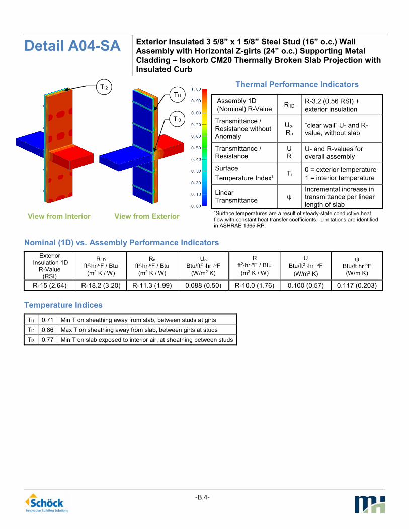
Detail A04-SA Exterior Insulated 3 5/8” x 1 5/8” Steel Stud (16” o.c.) Wall Assembly with Horizontal Z-girts (24” o.c.) Supporting Metal Cladding – Isokorb CM20 Thermally Broken Slab Projection with Insulated Curb
View from Interior
View from Exterior
Thermal Performance Indicators
Assembly 1D (Nominal) R-Value
R1D R-3.2 (0.56 RSI) + exterior insulation
Transmittance / Resistance without Anomaly
Uo, Ro
“clear wall” U- and R-value, without slab
Transmittance / Resistance
U R
U- and R-values for overall assembly
Surface
Temperature Index¹ Ti
0 = exterior temperature
1 = interior temperature
Linear Transmittance
ψ Incremental increase in transmittance per linear length of slab
¹Surface temperatures are a result of steady-state conductive heat flow with constant heat transfer coefficients. Limitations are identified in ASHRAE 1365-RP.
Nominal (1D) vs. Assembly Performance Indicators
Exterior Insulation 1D
R-Value (RSI)
R1D
ft2∙hr∙oF / Btu
(m2 K / W)
Ro ft2∙hr∙oF / Btu
(m2 K / W)
Uo
Btu/ft2 ∙hr ∙oF
(W/m2 K)
R
ft2∙hr∙oF / Btu
(m2 K / W)
U
Btu/ft2 ∙hr ∙oF
(W/m2 K)
ψ Btu/ft hr oF (W/m K)
R-15 (2.64) R-18.2 (3.20) R-11.3 (1.99) 0.088 (0.50) R-10.0 (1.76) 0.100 (0.57) 0.117 (0.203)
Temperature Indices
Ti1 0.71 Min T on sheathing away from slab, between studs at girts
Ti2 0.86 Max T on sheathing away from slab, between girts at studs
Ti3 0.77 Min T on slab exposed to interior air, at sheathing between studs
Ti2
Ti1
Ti3

-B.5-
Detail A05-CC Exterior and Interior Insulated 3 5/8” x 1 5/8” Steel Stud (16” o.c.) Wall Assembly with Horizontal Z-girts (24” o.c.) Supporting Metal Cladding – Un-insulated concrete slab intersection
View from Interior
View from Exterior
Thermal Performance Indicators
¹Surface temperatures are a result of steady-state conductive heat flow with constant heat transfer coefficients. Limitations are identified in ASHRAE 1365-RP.
Assembly 1D (Nominal) R-Value
R1D R-14.3 (2.52 RSI) + exterior insulation
Transmittance / Resistance
Uo, Ro
“clear wall” U- and R-value, without slab
Transmittance / Resistance
U, R
U- and R-values for overall assembly
Surface
Temperature Index¹ Ti
0 = exterior temperature
1 = interior temperature
Linear Transmittance
ψ Incremental increase in transmittance per linear length of slab
Nominal (1D) vs. Assembly Performance Indicators
Exterior Insulation 1D
R-Value
(RSI)
R1D
ft2∙hr∙oF / Btu
(m2 K / W)
Ro
ft2∙hr∙oF / Btu
(m2 K / W)
Uo
Btu/ft2 ∙hr ∙oF
(W/m2 K)
R
ft2∙hr∙oF / Btu
(m2 K / W)
U
Btu/ft2 ∙hr ∙oF
(W/m2 K)
ψ
Btu/ft ·hr·oF
(W/m K)
R-15 (2.64) R-29.3 (5.16) R-18.5 (3.25) 0.054 (0.31) R-8.6 (1.51) 0.116 (0.66) 0.612 (1.059)
Temperature Indices
Ti1 0.35 Min T on sheathing away from slab, between studs at girts
Ti2 0.73 Max T on sheathing away from slab, between girts at studs
Ti3 0.64 Min T on slab exposed to interior air, at gypsum between studs
Ti3
Ti1
Ti2

-B.6-
Detail A06-CC Exterior and Interior Insulated 3 5/8” x 1 5/8” Steel Stud (16” o.c.) Wall Assembly with Horizontal Z-girts (24” o.c.) Supporting Metal Cladding – Uninsulated Concrete Slab Intersection with Insulated Curb
View from Interior
View from Exterior
Thermal Performance Indicators
Assembly 1D (Nominal) R-Value
R1D R-14.3 (2.52 RSI) + exterior insulation
Transmittance / Resistance without Anomaly
Uo, Ro
“clear wall” U- and R-value, without slab
Transmittance / Resistance
U R
U- and R-values for overall assembly
Surface
Temperature Index¹ Ti
0 = exterior temperature
1 = interior temperature
Linear Transmittance
ψ Incremental increase in transmittance per linear length of slab
¹Surface temperatures are a result of steady-state conductive heat flow with constant heat transfer coefficients. Limitations are identified in ASHRAE 1365-RP.
Nominal (1D) vs. Assembly Performance Indicators
Exterior Insulation 1D
R-Value (RSI)
R1D
ft2∙hr∙oF / Btu
(m2 K / W)
Ro ft2∙hr∙oF / Btu
(m2 K / W)
Uo
Btu/ft2 ∙hr ∙oF
(W/m2 K)
R
ft2∙hr∙oF / Btu
(m2 K / W)
U
Btu/ft2 ∙hr ∙oF
(W/m2 K)
ψ Btu/ft hr oF (W/m K)
R-15 (2.64) R-29.3 (5.16) R-18.5 (3.25) 0.054 (0.31) R-9.3 (1.63) 0.108 (0.61) 0.528 (0.914)
Temperature Indices
Ti1 0.35 Min T on sheathing away from slab, between studs at girts
Ti2 0.73 Max T on sheathing away from slab, between girts at studs
Ti3 0.70 Min T on slab exposed to interior air, at gypsum between studs
Ti2
Ti1
Ti3

-B.7-
Detail A07-SA Exterior and Interior Insulated 3 5/8” x 1 5/8” Steel Stud (16” o.c.) Wall Assembly with Horizontal Z-girts (24” o.c.) Supporting Metal Cladding – Isokorb CM20 Thermally Broken Slab Projection with Uninsulated Curb
View from Interior
View from Exterior
Thermal Performance Indicators
Assembly 1D (Nominal) R-Value
R1D R-14.3 (2.52 RSI) + exterior insulation
Transmittance / Resistance without Anomaly
Uo, Ro
“clear wall” U- and R-value, without slab
Transmittance / Resistance
U R
U- and R-values for overall assembly
Surface
Temperature Index¹ Ti
0 = exterior temperature
1 = interior temperature
Linear Transmittance
ψ Incremental increase in transmittance per linear length of slab
¹Surface temperatures are a result of steady-state conductive heat flow with constant heat transfer coefficients. Limitations are identified in ASHRAE 1365-RP.
Nominal (1D) vs. Assembly Performance Indicators
Exterior Insulation 1D
R-Value (RSI)
R1D
ft2∙hr∙oF / Btu
(m2 K / W)
Ro ft2∙hr∙oF / Btu
(m2 K / W)
Uo
Btu/ft2 ∙hr ∙oF
(W/m2 K)
R
ft2∙hr∙oF / Btu
53(m2 K / W)
U
Btu/ft2 ∙hr ∙oF
(W/m2 K)
ψ Btu/ft hr oF (W/m K)
R-15 (2.64) R-29.3 (5.16) R-18.5 (3.25) 0.054 (0.31) R-11.6 (2.04) 0.087 (0.49) 0.319 (0.551)
Temperature Indices
Ti1 0.35 Min T on sheathing away from slab, between studs at girts
Ti2 0.73 Max T on sheathing away from slab, between girts at studs
Ti3 0.77 Min T on slab exposed to interior air, at gypsum between studs
Ti2
Ti1
Ti3

-B.8-
Detail A08-SA Exterior and Interior Insulated 3 5/8” x 1 5/8” Steel Stud (16” o.c.) Wall Assembly with Horizontal Z-girts (24” o.c.) Supporting Metal Cladding – Isokorb CM20 Thermally Broken Slab Projection with Insulated Curb
View from Interior
View from Exterior
Thermal Performance Indicators
Assembly 1D (Nominal) R-Value
R1D R-14.3 (2.52 RSI) + exterior insulation
Transmittance / Resistance without Anomaly
Uo, Ro
“clear wall” U- and R-value, without slab
Transmittance / Resistance
U R
U- and R-values for overall assembly
Surface
Temperature Index¹ Ti
0 = exterior temperature
1 = interior temperature
Linear Transmittance
ψ Incremental increase in transmittance per linear length of slab
¹Surface temperatures are a result of steady-state conductive heat flow with constant heat transfer coefficients. Limitations are identified in ASHRAE 1365-RP.
Nominal (1D) vs. Assembly Performance Indicators
Exterior Insulation 1D
R-Value (RSI)
R1D
ft2∙hr∙oF / Btu
(m2 K / W)
Ro ft2∙hr∙oF / Btu
(m2 K / W)
Uo
Btu/ft2 ∙hr ∙oF
(W/m2 K)
R
ft2∙hr∙oF / Btu
(m2 K / W)
U
Btu/ft2 ∙hr ∙oF
(W/m2 K)
ψ Btu/ft hr oF (W/m K)
R-15 (2.64) R-29.3 (5.16) R-18.5 (3.25) 0.054 (0.31) R-13.6 (2.40) 0.073 (0.42) 0.189 (0.327)
Temperature Indices
Ti1 0.35 Min T on sheathing away from slab, between studs at girts
Ti2 0.73 Max T on sheathing away from slab, between girts at studs
Ti3 0.85 Min T on slab exposed to interior air, at gypsum between studs
Ti2 Ti1
Ti3
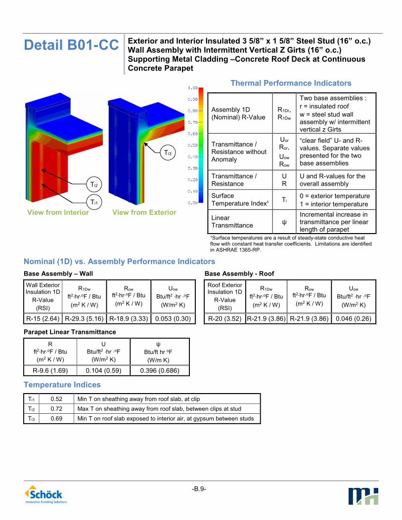
-B.9-
Detail B01-CC Exterior and Interior Insulated 3 5/8” x 1 5/8” Steel Stud (16” o.c.) Wall Assembly with Intermittent Vertical Z Girts (16” o.c.) Supporting Metal Cladding –Concrete Roof Deck at Continuous Concrete Parapet
View from Interior
View from Exterior
Thermal Performance Indicators
Assembly 1D (Nominal) R-Value
R1Dr, R1Dw
Two base assemblies :
r = insulated roof
w = steel stud wall assembly w/ intermittent vertical z Girts
Transmittance / Resistance without Anomaly
Uor Ror,
Uow
Row
“clear field” U- and R-values. Separate values presented for the two base assemblies
Transmittance / Resistance
U R
U and R-values for the overall assembly
Surface
Temperature Index¹ Ti
0 = exterior temperature
1 = interior temperature
Linear Transmittance
ψ Incremental increase in transmittance per linear length of parapet
¹Surface temperatures are a result of steady-state conductive heat flow with constant heat transfer coefficients. Limitations are identified in ASHRAE 1365-RP.
Nominal (1D) vs. Assembly Performance Indicators
Base Assembly – Wall Base Assembly - Roof
Wall Exterior Insulation 1D
R-Value
(RSI)
R1Dw
ft2∙hr∙oF / Btu
(m2 K / W)
Row ft2∙hr∙oF / Btu
(m2 K / W)
Uow
Btu/ft2 ∙hr ∙oF
(W/m2 K)
Roof Exterior Insulation 1D
R-Value
(RSI)
R1Dw
ft2∙hr∙oF / Btu
(m2 K / W)
Row ft2∙hr∙oF / Btu
(m2 K / W)
Uow
Btu/ft2 ∙hr ∙oF
(W/m2 K)
R-15 (2.64) R-29.3 (5.16) R-18.9 (3.33) 0.053 (0.30) R-20 (3.52) R-21.9 (3.86) R-21.9 (3.86) 0.046 (0.26)
Parapet Linear Transmittance
R
ft2∙hr∙oF / Btu
(m2 K / W)
U
Btu/ft2 ∙hr ∙oF
(W/m2 K)
ψ
Btu/ft hr oF
(W/m K)
R-9.6 (1.69) 0.104 (0.59) 0.396 (0.686)
Temperature Indices
Ti1 0.52 Min T on sheathing away from roof slab, at clip
Ti2 0.72 Max T on sheathing away from roof slab, between clips at stud
Ti3 0.69 Min T on roof slab exposed to interior air, at gypsum between studs
Ti1
Ti2
Ti3
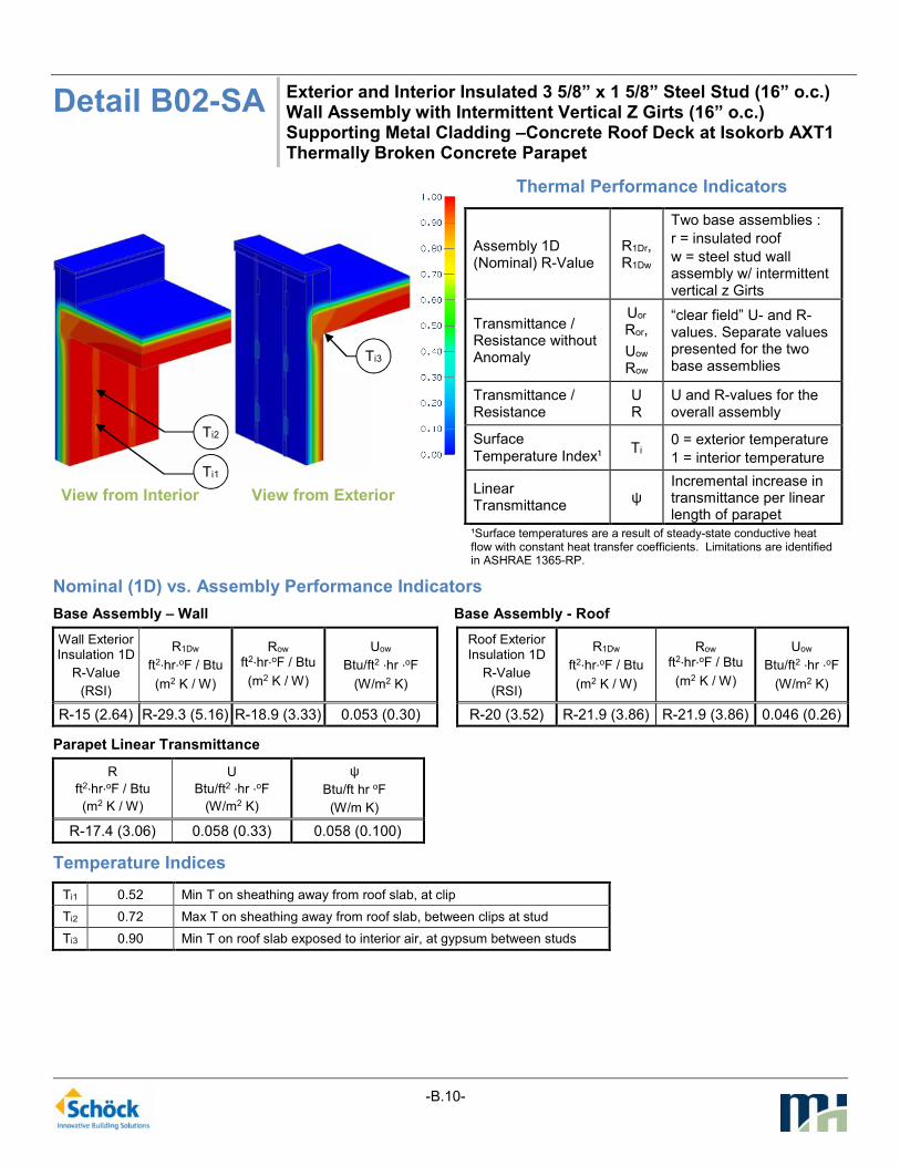
-B.10-
Detail B02-SA Exterior and Interior Insulated 3 5/8” x 1 5/8” Steel Stud (16” o.c.) Wall Assembly with Intermittent Vertical Z Girts (16” o.c.) Supporting Metal Cladding –Concrete Roof Deck at Isokorb AXT1 Thermally Broken Concrete Parapet
View from Interior
View from Exterior
Thermal Performance Indicators
Assembly 1D (Nominal) R-Value
R1Dr, R1Dw
Two base assemblies :
r = insulated roof
w = steel stud wall assembly w/ intermittent vertical z Girts
Transmittance / Resistance without Anomaly
Uor Ror,
Uow
Row
“clear field” U- and R-values. Separate values presented for the two base assemblies
Transmittance / Resistance
U R
U and R-values for the overall assembly
Surface
Temperature Index¹ Ti
0 = exterior temperature
1 = interior temperature
Linear Transmittance
ψ Incremental increase in transmittance per linear length of parapet
¹Surface temperatures are a result of steady-state conductive heat flow with constant heat transfer coefficients. Limitations are identified in ASHRAE 1365-RP.
Nominal (1D) vs. Assembly Performance Indicators
Base Assembly – Wall Base Assembly - Roof
Wall Exterior Insulation 1D
R-Value
(RSI)
R1Dw
ft2∙hr∙oF / Btu
(m2 K / W)
Row ft2∙hr∙oF / Btu
(m2 K / W)
Uow
Btu/ft2 ∙hr ∙oF
(W/m2 K)
Roof Exterior Insulation 1D
R-Value
(RSI)
R1Dw
ft2∙hr∙oF / Btu
(m2 K / W)
Row ft2∙hr∙oF / Btu
(m2 K / W)
Uow
Btu/ft2 ∙hr ∙oF
(W/m2 K)
R-15 (2.64) R-29.3 (5.16) R-18.9 (3.33) 0.053 (0.30) R-20 (3.52) R-21.9 (3.86) R-21.9 (3.86) 0.046 (0.26)
Parapet Linear Transmittance
R
ft2∙hr∙oF / Btu
(m2 K / W)
U
Btu/ft2 ∙hr ∙oF
(W/m2 K)
ψ
Btu/ft hr oF
(W/m K)
R-17.4 (3.06) 0.058 (0.33) 0.058 (0.100)
Temperature Indices
Ti1 0.52 Min T on sheathing away from roof slab, at clip
Ti2 0.72 Max T on sheathing away from roof slab, between clips at stud
Ti3 0.90 Min T on roof slab exposed to interior air, at gypsum between studs
Ti1
Ti2
Ti3

-B.11-
Detail C01-CC Exterior and Interior Insulated 3 5/8” x 1 5/8” Steel Stud (16” o.c.) Wall Assembly with Horizontal Z-girts (24” o.c.) Supporting Metal Cladding – Structural Steel Floor Intersection with Uninterrupted Beam
View from Interior
View from Exterior
Thermal Performance Indicators
Assembly 1D (Nominal) R-Value
R1D R-14.3 (2.52 RSI) + exterior insulation
Transmittance / Resistance without Anomaly
Uo, Ro
“clear wall” U- and R-value without slab or beam
Transmittance / Resistance
Us Rs
U and R-values for steel stud wall with slab
Transmittance / Resistance
U R
U and R-values for the overall assembly
Surface
Temperature Index¹ Ti
0 = exterior temperature
1 = interior temperature
Linear Transmittance
ψs Incremental increase in transmittance per linear length of floor slab
Point Transmittance
χ
Incremental increase in transmittance for beam penetration
¹Surface temperatures are a result of steady-state conductive heat flow with constant heat transfer coefficients. Limitations are identified in ASHRAE 1365-RP.
Nominal (1D) vs. Assembly Performance Indicators
Base Assembly – Wall Beam Point Transmittance
Wall Exterior Insulation 1D
R-Value
(RSI)
R1D
ft2·hr·oF / Btu (m2 K / W)
Ro ft2∙hr∙oF / Btu
(m2 K / W)
Uo
Btu/ft2 ∙hr ∙oF
(W/m2 K)
R ft2∙hr∙oF / Btu
(m2 K / W)
U
Btu/ft2 ∙hr ∙oF
(W/m2 K)
χ
Btu/hr oF (W/K)
R-15 (2.64) R-29.3 (5.16) R-18.5 (3.25) 0.054 (0.31) R-6.9 (1.21) 0.146 (0.83) 1.73 (0.92)
Slab Linear Transmittance
Rs
ft2·hr·oF / Btu (m2 K / W)
Us
Btu/ft2 ∙hr ∙oF
(W/m2 K)
ψs
Btu/ft hr oF (W/m K)
R-15.6 (2.75) 0.064 (0.36) 0.083 (0.143)
Temperature Indices
Ti1 0.35 Min T on sheathing away from slab, between studs at girts
Ti2 0.73 Max T on sheathing away from slab, between girts at studs
Ti3 0.52 Min T on beam exposed to interior air, top flange at I-beam intersection
Ti2
Ti3
Ti1

-B.12-
Detail C02-TI Exterior and Interior Insulated 3 5/8” x 1 5/8” Steel Stud (16” o.c.) Wall Assembly with Horizontal Z-girts (24” o.c.) Supporting Metal Cladding – Structural Steel Floor Intersection with Isolator Pad
View from Interior
View from Exterior
Thermal Performance Indicators
Assembly 1D (Nominal) R-Value
R1D R-14.3 (2.52 RSI) + exterior insulation
Transmittance / Resistance without Anomaly
Uo, Ro
“clear wall” U- and R-value without slab or beam
Transmittance / Resistance
Us Rs
U and R-values for steel stud wall with slab
Transmittance / Resistance
U R
U and R-values for the overall assembly
Surface
Temperature Index¹ Ti
0 = exterior temperature
1 = interior temperature
Linear Transmittance
ψs Incremental increase in transmittance per linear length of floor slab
Point Transmittance
χ
Incremental increase in transmittance for beam penetration
¹Surface temperatures are a result of steady-state conductive heat flow with constant heat transfer coefficients. Limitations are identified in ASHRAE 1365-RP.
Nominal (1D) vs. Assembly Performance Indicators
Base Assembly – Wall
Wall Exterior Insulation 1D
R-Value
(RSI)
R1D
ft2∙hr∙oF / Btu
(m2 K / W)
Ro
ft2∙hr∙oF / Btu
(m2 K / W)
Uo
Btu/ft2 ∙hr ∙oF
(W/m2 K)
R-15 (2.64) R-29.3 (5.16) R-18.5 (3.25) 0.054 (0.31)
Slab Linear Transmittance
Rs ft2∙hr∙oF / Btu
(m2 K / W)
Us
Btu/ft2 ∙hr ∙oF
(W/m2 K)
ψs
Btu/ft hr oF (W/m K)
R-15.6 (2.75) 0.064 (0.36) 0.083 (0.143)
Beam Point Transmittance
Thermal Isolator Pad
R ft2∙hr∙oF / Btu
(m2 K / W)
U
Btu/ft2 ∙hr ∙oF
(W/m2 K)
χ
Btu/hr oF
(W/K)
5 mm pad, stainless steel bolts
R-6.0 (1.06) 0.167 (0.95) 2.17 (1.15)
5 mm pad, steel bolts R-5.9 (1.04) 0.170 (0.97) 2.24 (1.19)
5 mm pad, stainless steel bolts, w/ R10 outboard of plates
R-6.4 (1.13) 0.156 (0.89) 1.80 (1.03)
10 mm pad, stainless steel bolts
R-6.7 (1.17) 0.150 (0.85) 1.82 (0.97)
10 mm pad, steel bolts R-6.5 (1.15) 0.153 (0.87) 1.89 (1.00)
19 mm pad, steel bolts R-6.9 (1.22) 0.145 (0.82) 1.71 (0.91)
25 mm pad, steel bolts R-7.1 (1.25) 0.140 (0.80) 1.61 (0.86)
Temperature Indices
5 mm pad,
stainless bolts
5 mm pad, steel bolts
5 mm pad, stainless
bolts, w/ R10
10 mm pad,
stainless bolts
10 mm pad, steel
bolts
Ti1 0.35 0.35 0.35 0.35 0.35 Min T on sheathing away from slab, between studs at girts
Ti2 0.73 0.73 0.73 0.73 0.73 Max T on sheathing away from slab, between girts at studs
Ti3 0.33 0.32 0.39 0.42 0.41 Min T on beam exposed to interior air, top flange at I-beam intersection
Ti2
Ti3
Ti1

-B.13-
Detail C03-SA Exterior and Interior Insulated 3 5/8” x 1 5/8” Steel Stud (16” o.c.) Wall Assembly with Horizontal Z-girts (24” o.c.) Supporting Metal Cladding – Structural Steel Floor Intersection with Isokorb S22 Thermally Broken Beam
View from Interior
View from Exterior
Thermal Performance Indicators
Assembly 1D (Nominal) R-Value
R1D R-14.3 (2.52 RSI) + exterior insulation
Transmittance / Resistance without Anomaly
Uo, Ro
“clear wall” U- and R-value without slab or beam
Transmittance / Resistance
Us Rs
U and R-values for steel stud wall with slab
Transmittance / Resistance
U R
U and R-values for the overall assembly
Surface
Temperature Index¹ Ti
0 = exterior temperature
1 = interior temperature
Linear Transmittance
ψs Incremental increase in transmittance per linear length of floor slab
Point Transmittance
χ
Incremental increase in transmittance for beam penetration
¹Surface temperatures are a result of steady-state conductive heat flow with constant heat transfer coefficients. Limitations are identified in ASHRAE 1365-RP.
Nominal (1D) vs. Assembly Performance Indicators
Base Assembly – Wall Beam Point Transmittance
Wall Exterior Insulation 1D
R-Value
(RSI)
Rw1D
ft2·hr·oF / Btu (m2 K / W)
Ro ft2∙hr∙oF / Btu
(m2 K / W)
Uo
Btu/ft2 ∙hr ∙oF
(W/m2 K)
R ft2∙hr∙oF / Btu
(m2 K / W)
U
Btu/ft2 ∙hr ∙oF
(W/m2 K)
χ
Btu/hr oF (W/K)
R-15 (2.64) R-29.3 (5.16) R-18.5 (3.25) 0.054 (0.31) R-9.4 (1.65) 0.107 (0.61) 0.91 (0.48)
Slab Linear Transmittance
Rs
ft2·hr·oF / Btu (m2 K / W)
Us
Btu/ft2 ∙hr ∙oF
(W/m2 K)
ψs
Btu/ft hr oF (W/m K)
R-15.6 (2.75) 0.064 (0.36) 0.083 (0.143)
Temperature Indices
Ti1 0.32 Min T on sheathing away from slab, between studs at girts
Ti2 0.89 Max T on sheathing away from slab, between girts at studs
Ti3 0.79 Min T on beam exposed to interior air, top flange at I-beam intersection
Ti3
Ti1
Ti2

-B.14-
Detail D01-CC Exterior Insulated 3 5/8” x 1 5/8” Steel Stud (16” o.c.) Wall Assembly with Intermittent Vertical Z-girts (16” o.c.) Supporting Metal Cladding – Concrete Floor to Steel Beam Connection
View from Interior
View from Exterior
Thermal Performance Indicators
Assembly 1D (Nominal) R-Value
R1D R-3.2 (0.56 RSI) + exterior insulation
Transmittance / Resistance without Anomaly
Uo, Ro
“clear wall” U- and R-value without slab or beam
Transmittance / Resistance
Us Rs
U and R-values for steel stud wall with slab
Transmittance / Resistance
U R
U and R-values for the overall assembly
Surface
Temperature Index¹ Ti
0 = exterior temperature
1 = interior temperature
Linear Transmittance
ψs Incremental increase in transmittance per linear length of floor slab
Point Transmittance
χ
Incremental increase in transmittance for beam penetration
¹Surface temperatures are a result of steady-state conductive heat flow with constant heat transfer coefficients. Limitations are identified in ASHRAE 1365-RP.
Nominal (1D) vs. Assembly Performance Indicators
Base Assembly – Wall Beam Point Transmittance
Exterior Insulation 1D
R-Value (RSI)
R1D
ft2∙hr∙oF / Btu
(m2 K / W)
Ro ft2∙hr∙oF / Btu
(m2 K / W)
Uo
Btu/ft2 ∙hr ∙oF
(W/m2 K)
R ft2∙hr∙oF / Btu
(m2 K / W)
U
Btu/ft2 ∙hr ∙oF
(W/m2 K)
χ
Btu/hr oF (W/K)
R-15 (2.64) R-18.2 (3.20) R-13.8 (2.44) 0.072 (0.41) R-7.3 (1.28) 0.137 (0.78) 1.24 (0.66)
Slab Linear Transmittance
Rs
ft2·hr·oF / Btu (m2 K / W)
Us
Btu/ft2 ∙hr ∙oF
(W/m2 K)
ψs
Btu/ft hr oF (W/m K)
R-12.7 (2.24) 0.079 (0.45) 0.052 (0.090)
Temperature Indices
Ti1 0.44 Min T on sheathing, at slab, in line with beam
Ti2 0.88 Max T on sheathing, at studs, between clips
Ti3 0.40 Min T on slab exposed to interior air, at sheathing, in line with beam
Ti2
Ti3
Ti1

-B.15-
Detail D02-TI Exterior Insulated 3 5/8” x 1 5/8” Steel Stud (16” o.c.) Wall Assembly with Intermittent Vertical Z-girts (16” o.c.) Supporting Metal Cladding – Concrete Floor to Steel Beam with a Thermal Isolator Pad Connection
View from Interior
View from Exterior
Thermal Performance Indicators
Assembly 1D (Nominal) R-Value
R1D R-3.2 (0.56 RSI) + exterior insulation
Transmittance / Resistance without Anomaly
Uo, Ro
“clear wall” U- and R-value without slab or beam
Transmittance / Resistance
Us Rs
U and R-values for steel stud wall with slab
Transmittance / Resistance
U R
U and R-values for the overall assembly
Surface
Temperature Index¹ Ti
0 = exterior temperature
1 = interior temperature
Linear Transmittance
ψs Incremental increase in transmittance per linear length of floor slab
Point Transmittance
χ
Incremental increase in transmittance for beam penetration
¹Surface temperatures are a result of steady-state conductive heat flow with constant heat transfer coefficients. Limitations are identified in ASHRAE 1365-RP.
Nominal (1D) vs. Assembly Performance Indicators
Base Assembly – Wall Beam Point Transmittance
Exterior Insulation 1D
R-Value (RSI)
R1D
ft2∙hr∙oF / Btu
(m2 K / W)
Ro ft2∙hr∙oF / Btu
(m2 K / W)
Uo
Btu/ft2 ∙hr ∙oF
(W/m2 K)
R ft2∙hr∙oF / Btu
(m2 K / W)
U
Btu/ft2 ∙hr ∙oF
(W/m2 K)
χ
Btu/hr oF (W/K)
R-15 (2.64) R-18.2 (3.20) R-13.8 (2.44) 0.072 (0.41) R-8.2 (1.45) 0.121 (0.69) 0.91 (0.48)
Slab Linear Transmittance
Rs
ft2·hr·oF / Btu (m2 K / W)
Us
Btu/ft2 ∙hr ∙oF
(W/m2 K)
ψs
Btu/ft hr oF (W/m K)
R-12.7 (2.24) 0.079 (0.45) 0.052 (0.090)
Temperature Indices
Ti1 0.44 Min T on sheathing, at slab, in line with beam
Ti2 0.88 Max T on sheathing, at studs, between clips
Ti3 0.54 Min T on slab exposed to interior air, at sheathing, in line with beam
Ti1
Ti2
Ti3

-B.16-
Detail D03-SA Exterior Insulated 3 5/8” x 1 5/8” Steel Stud (16” o.c.) Wall Assembly with Intermittent Vertical Z-girts (16” o.c.) Supporting Metal Cladding – Concrete Floor to Steel Beam with Isokorb KS14 Connection
View from Interior
View from Exterior
Thermal Performance Indicators
Assembly 1D (Nominal) R-Value
R1D R-3.2 (0.56 RSI) + exterior insulation
Transmittance / Resistance without Anomaly
Uo, Ro
“clear wall” U- and R-value without slab or beam
Transmittance / Resistance
Us Rs
U and R-values for steel stud wall with slab
Transmittance / Resistance
U R
U and R-values for the overall assembly
Surface
Temperature Index¹ Ti
0 = exterior temperature
1 = interior temperature
Linear Transmittance
ψs Incremental increase in transmittance per linear length of floor slab
Point Transmittance
χ
Incremental increase in transmittance for beam penetration
¹Surface temperatures are a result of steady-state conductive heat flow with constant heat transfer coefficients. Limitations are identified in ASHRAE 1365-RP.
Nominal (1D) vs. Assembly Performance Indicators
Base Assembly – Wall Beam Point Transmittance
Exterior Insulation 1D
R-Value (RSI)
R1D
ft2∙hr∙oF / Btu
(m2 K / W)
Ro ft2∙hr∙oF / Btu
(m2 K / W)
Uo
Btu/ft2 ∙hr ∙oF
(W/m2 K)
R ft2∙hr∙oF / Btu
(m2 K / W)
U
Btu/ft2 ∙hr ∙oF
(W/m2 K)
χ
Btu/hr oF (W/K)
R-15 (2.64) R-18.2 (3.20) R-13.8 (2.44) 0.072 (0.41) R-12.2 (2.14) 0.082 (0.47) 0.07 (0.04)
Slab Linear Transmittance
Rs
ft2·hr·oF / Btu (m2 K / W)
Us
Btu/ft2 ∙hr ∙oF
(W/m2 K)
ψs
Btu/ft hr oF (W/m K)
R-12.7 (2.24) 0.079 (0.45) 0.052 (0.090)
Temperature Indices
Ti1 0.44 Min T on sheathing, at slab, in line with beam
Ti2 0.88 Max T on sheathing, at studs, between clips
Ti3 0.84 Min T on slab exposed to interior air, at sheathing, in line with beam
Ti1
Ti2
Ti3
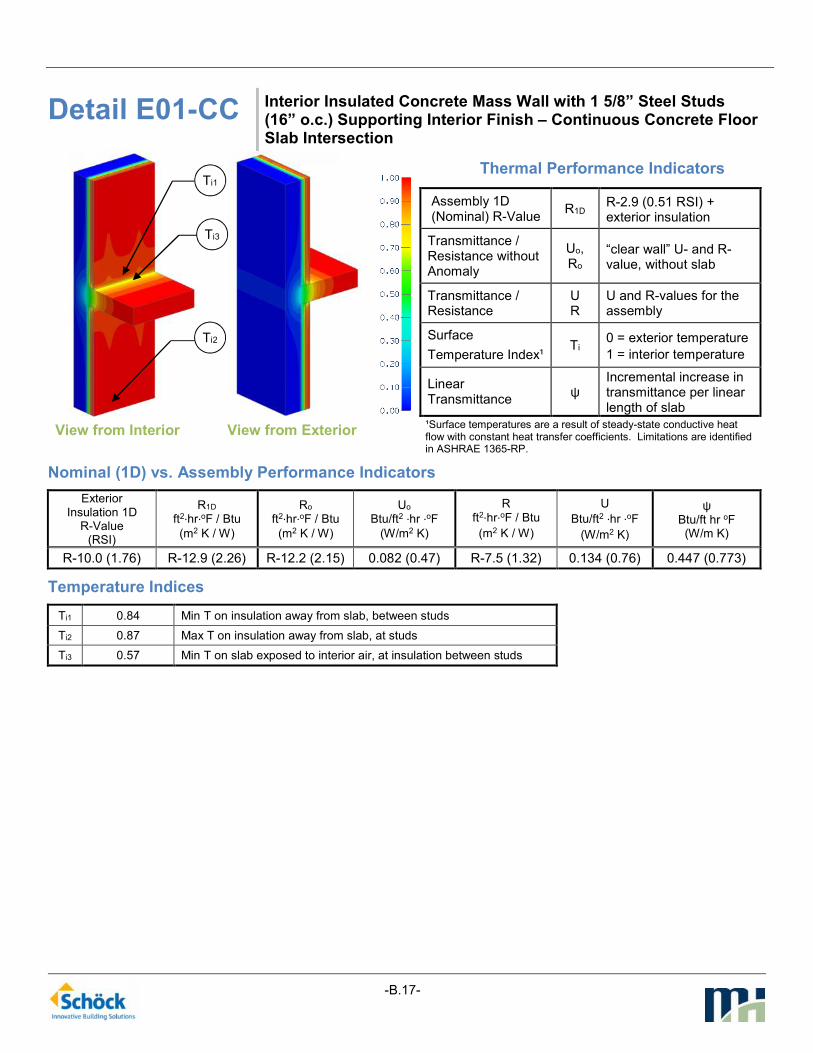
-B.17-
Detail E01-CC Interior Insulated Concrete Mass Wall with 1 5/8” Steel Studs (16” o.c.) Supporting Interior Finish – Continuous Concrete Floor Slab Intersection
View from Interior
View from Exterior
Thermal Performance Indicators
Assembly 1D (Nominal) R-Value
R1D R-2.9 (0.51 RSI) + exterior insulation
Transmittance / Resistance without Anomaly
Uo, Ro
“clear wall” U- and R-value, without slab
Transmittance / Resistance
U R
U and R-values for the assembly
Surface
Temperature Index¹ Ti
0 = exterior temperature
1 = interior temperature
Linear Transmittance
ψ Incremental increase in transmittance per linear length of slab
¹Surface temperatures are a result of steady-state conductive heat flow with constant heat transfer coefficients. Limitations are identified in ASHRAE 1365-RP.
Nominal (1D) vs. Assembly Performance Indicators
Exterior Insulation 1D
R-Value (RSI)
R1D
ft2∙hr∙oF / Btu
(m2 K / W)
Ro ft2∙hr∙oF / Btu
(m2 K / W)
Uo
Btu/ft2 ∙hr ∙oF
(W/m2 K)
R
ft2∙hr∙oF / Btu
(m2 K / W)
U
Btu/ft2 ∙hr ∙oF
(W/m2 K)
ψ Btu/ft hr oF (W/m K)
R-10.0 (1.76) R-12.9 (2.26) R-12.2 (2.15) 0.082 (0.47) R-7.5 (1.32) 0.134 (0.76) 0.447 (0.773)
Temperature Indices
Ti1 0.84 Min T on insulation away from slab, between studs
Ti2 0.87 Max T on insulation away from slab, at studs
Ti3 0.57 Min T on slab exposed to interior air, at insulation between studs
Ti2
Ti3
Ti1

-B.18-
Detail E02-SA Interior Insulated Concrete Mass Wall with 1 5/8” Steel Studs (16” o.c.) Supporting Interior Finish – Isokorb Rutherma DF Thermally Broken Concrete Floor Slab Intersection
View from Interior
View from Exterior
Thermal Performance Indicators
Assembly 1D (Nominal) R-Value
R1D R-2.9 (0.51 RSI) + exterior insulation
Transmittance / Resistance without Anomaly
Uo, Ro
“clear wall” U- and R-value, without slab
Transmittance / Resistance
U R
U and R-values for the assembly
Surface
Temperature Index¹ Ti
0 = exterior temperature
1 = interior temperature
Linear Transmittance
ψ Incremental increase in transmittance per linear length of slab
¹Surface temperatures are a result of steady-state conductive heat flow with constant heat transfer coefficients. Limitations are identified in ASHRAE 1365-RP.
Nominal (1D) vs. Assembly Performance Indicators
Exterior Insulation 1D
R-Value (RSI)
R1D
ft2∙hr∙oF / Btu
(m2 K / W)
Ro ft2∙hr∙oF / Btu
(m2 K / W)
Uo
Btu/ft2 ∙hr ∙oF
(W/m2 K)
R
ft2∙hr∙oF / Btu
(m2 K / W)
U
Btu/ft2 ∙hr ∙oF
(W/m2 K)
ψ Btu/ft hr oF (W/m K)
R-10.0 (1.76) R-12.9 (2.26) R-12.2 (2.15) 0.082 (0.47) R-9.7 (1.72) 0.103 (0.58) 0.179 (0.310)
Temperature Indices
Ti1 0.84 Min T on insulation away from slab, between studs
Ti2 0.87 Max T on insulation away from slab, at studs
Ti3 0.70 Min T on slab exposed to interior air, at insulation between studs
Ti2
Ti3
Ti1

APPENDIX C: Thermal Resistance Tables

-C.1-
Table C1: Thermal resistance of of R-15 exterior insulated steel stud assemblies with cantilevered concrete slab
Scenario Description
Clear Wall R-
value ft² ·hr ·°F/Btu
(m²K/W)
Overall R-
value ft² ·hr ·°F/Btu
(m²K/W)
ψ Btu/ft ·hr ·°F
(W/mK)
%
Reduction
in Heat
Loss
Co
nv
en
tio
na
l
Co
nst
ruc
tio
n
A01-CC Without insulation at
curb R-11.3 (1.99) R-6.8 (1.19) 0.584 (1.011) -
A02-CC With insulation at curb R-11.3 (1.99) R-7.3 (1.28) 0.485 (0.840) 17%
Ma
nu
fac
ture
d
The
rma
l B
rea
k
(Iso
ko
rb C
M20
)
A03-SA Without insulation at
curb R-11.3 (1.99) R-8.7 (1.53) 0.261 (0.452) 55%
A04-SA With insulation at curb R-11.3 (1.99) R-10 (1.76) 0.117 (0.203) 80%
Table C2: Thermal resistance of R-15/R-12 split insulated steel stud assemblies with cantilevered concrete slab
Scenario Description
Clear Wall
R-value ft² ·hr ·°F/Btu
(m²K/W)
Overall R-
value ft² ·hr ·°F/Btu
(m²K/W)
ψ
Btu/ft ·hr ·°F
(W/mK)
%
Reduction
in Heat
Loss
Co
nv
en
tio
na
l
Co
nst
ruc
tio
n
A05-CC Without insulation
at curb R-18.5 (3.25) R-8.6 (1.51) 0.612 (1.059) -
A06-CC With insulation at
curb R-18.5 (3.25) R-9.3 (1.63) 0.528 (0.914) 14%
Ma
nu
fac
ture
d
The
rma
l B
rea
k
(Iso
ko
rb C
M20
)
A07-SA Without insulation
at curb R-18.5 (3.25) R-11.6 (2.04) 0.319 (0.528) 48%
A08-SA With insulation at
curb R-18.5 (3.25) R-13.6 (2.4) 0.189 (0.327) 69%

-C.2-
Table C3: Thermal resistance of R-15/R-12 split insulated steel stud assembly at a concrete parapet and roof deck
with R-20 insulation
Scenario Description
Clear Wall
R-value ft² ·hr ·°F/Btu
(m²K/W)
Clear Roof
R-value ft² ·hr ·°F/Btu
(m²K/W)
Overall R-
value ft² ·hr ·°F/Btu
(m²K/W)
ψ
Btu/ft ·hr ·°F
(W/mK)
%
Reduction
in Heat
Loss
Co
nv
en
tio
na
l
Co
nst
ruc
tio
n
B01-CC
Continuous
concrete
parapet
bypassing
interior wall
and roof
insulation
R-18.9 (3.33) R-21.9 (3.86) R-9.6 (1.69) 0.396 (0.686) -
Ma
nu
fac
ture
d
The
rma
l B
rea
k
(Iso
ko
rb A
XT1
)
B02- SA
Concrete
parapet and
roof
separated by
AXT1 Thermal
Break
R-18.9 (3.33) R-21.9 (3.86) R-17.4 (3.06) 0.058 (0.100) 85%
Table C4: Thermal resistance of structural steel beam penetration through R-15/R-12 split insulated steel stud
assembly
Scenario Description
Clear Wall
R-value ft² ·hr ·°F/Btu
(m²K/W)
Overall R-
value ft² ·hr ·°F/Btu
(m²K/W)
χ Btu/hr ·°F
(W/K)
%
Reduction
in Heat
Loss
Co
nv
en
tio
na
l
Co
nst
ruc
tio
n
C01-CC Uninterrupted steel through beam R-18.5 (3.25) R-6.9 (1.21) 1.73 (0.92) -
The
rma
l Is
ola
tor
Pa
d
C02-TI
5 mm isolator pad, stainless steel
bolts R-18.5 (3.25) R-6 (1.06) 2.17 (1.15) -26%
5 mm isolator pad, steel bolts R-18.5 (3.25) R-5.9 (1.04) 2.24 (1.19) -30%
5 mm pad, stainless steel bolts, R-
10 outboard of flanges R-18.5 (3.25) R-6.4 (1.13) 1.94 (1.03) -12%
10 mm isolator pad, stainless steel
bolts R-18.5 (3.25) R-6.7 (1.17) 1.82 (0.97) -5%
10 mm isolator pad, steel bolts R-18.5 (3.25) R-6.5 (1.15) 1.89 (1.00) -9%
19 mm isolator pad, steel bolts R-18.5 (3.25) R-6.9 (1.22) 1.71 (0.91) 1%
25 mm isolator pad, steel bolts R-18.5 (3.25) R-7.1 (1.25) 1.61 (0.86) 7%
Ma
nu
fac
ture
d
The
rma
l B
rea
k
(Iso
ko
rb S
22)
C03-SA Steel beam separated by Isokorb
S22 thermal break R-18.5 (3.25) R-9.4 (1.65) 0.91 (0.48) 48%

-C.3-
Table C5: Thermal resistance of concrete floor slab to structural steel balcony with a R-15/R-12 split insulated steel
stud wall assembly
Scenario Description
Clear Wall
R-value ft² ·hr ·°F/Btu
(m²K/W)
Overall R-
value ft² ·hr ·°F/Btu
(m²K/W)
χ Btu/hr ·°F
(W/K)
%
Reduction
in Heat
Loss
Co
nv
en
tio
na
l
Co
nst
ruc
tio
n
D01-CC
Steel beam
bypassing exterior
insulation
R-13.8 (2.44) R-7.3 (1.28) 1.24 (0.66) -
The
rma
l
Iso
lato
r P
ad
D02-TI
10mm Isolator pad
between steel
beam and
concrete
R-13.8 (2.44) R-8.2 (1.45) 0.91 (0.48) 27%
Ma
nu
fac
ture
d
The
rma
l B
rea
k
(Iso
ko
rb K
S1
4)
D03-SA
Isokorb KS14
thermal break
between steel
beam and
concrete
R-13.8 (2.44) R-12.2 (2.14) 0.07 (0.04) 94%
Table C6: Thermal resistance of R-10 Interior insulated poured-in place concrete wall at floor slab interface
Scenario Description
Clear Wall
R-value ft² ·hr ·°F/Btu
(m²K/W)
Overall R-
value ft² ·hr ·°F/Btu
(m²K/W)
ψ
Btu/ft ·hr ·°F
(W/mK)
%
Reduction
in Heat
Loss
Co
nv
en
tio
na
l
Co
nst
ruc
tio
n
E01-CC
Continuous
concrete floor to
wall connection,
bypassing interior
insulation
R-12.2 (2.15) R-7.5 (1.32) 0.447 (0.773) -
Ma
nu
fac
ture
d
The
rma
l B
rea
k
(Iso
ko
rb R
uth
erm
a D
F)
E02-SA
Concrete wall and
floor separated by
Rutherma DF
Thermal Break
R-12.2 (2.15) R-9.7 (1.72) 0.179 (0.310) 60%

APPENDIX D: Design Condition Thermal Profiles

-D.1-
Table D1: Thermal profiles for cantilevered concrete with exterior insulated steel stud assembly
A01-CC: Without curb insulation, without
thermal break
A03-SA: Without curb insulation, with
Isokorb CM20
A02-CC: With curb insulation, without
thermal break
A04-SA: With curb insulation, with Isokorb
CM20

-D.2-
Table D2: Thermal profiles for cantilevered concrete with split insulated steel stud assembly
A05-CC: Without curb insulation, without
thermal break
A07-SA: Without curb insulation, with
Isokorb CM20
A06-CC: With curb insulation, without
thermal break
A08-SA: With curb insulation, with Isokorb
CM20

-D.3-
Table D3: Temperature profiles for concrete parapets
B01-CC: Continuous concrete bypassing
insulation B02-SA: Isokorb AXT1
Table D4: Temperature profiles for steel to steel connections
C01-CC: Continuous steel
through beam
C02-TI: 5mm isolator pad,
steel bolts
C03-SA: Isokorb S22 thermal
break

-D.4-
Table D5: Temperature profiles for concrete floor slabs to steel connections
D01-CC: Steel beam
bypassing exterior insulation
D02-TI: 10 mm pad, steel
bolts
D03-SA: Isokorb KS14
thermal break
Table D6: Temperature profiles for interior insulated poured-in-place concrete
E01-CC: Continuous concrete bypassing
insulation E02-SA: Isokorb Rutherma DF