thermal energy storage - irena | home tech... · thermal energy storage systems can be either...
TRANSCRIPT

IEA-ETSAP and IRENA© Technology Brief E17 – January 2013www.etsap.org – www.irena.org
Thermal Energy Storage
Technology Brief
International Renewable Energy Agency
IRENAENERGY TECHNOLOGY SYSTEMS ANALYSIS PROGRAMME

This brief is available for download from the following IEA-ETSAP and IRENA sitesiea-etsap.org/web/Supply.aspwww.irena.org/Publications
Copyright © IEA-ETSAP and IRENA 2013
About IRENAThe International Renewable Energy Agency (IRENA) is an intergovernmental organiza-tion dedicated to renewable energy. In accordance with its Statute, IRENA’s objective is to “promote the widespread and increased adoption, and the sustainable use of all forms of renewable energy”. This concerns all forms of energy produced from renewable sources in a sustainable manner and includes bioenergy, geothermal energy, hydropower, ocean, solar and wind energy.
As of December 2012, the membership of IRENA comprises some 160 States and the European Union (EU), out of which 104 States and the EU have ratifi ed the Statute.
About IEA-ETSAPThe Energy Technology Systems Analysis Programme (ETSAP) is an Implementing Agree-ment of the International Energy Agency (IEA), fi rst established in 1976. It functions as a consortium of member country teams and invited teams that actively cooperate to establish, maintain, and expand a consistent multi-country energy/economy/environment/engineering (4E) analytical capability.
Its backbone consists of individual national teams in nearly 70 countries, and a common, comparable and combinable methodology, mainly based on the MARKAL / TIMES family of models, permitting the compilation of long term energy scenarios and in-depth national, multi-country, and global energy and environmental analyses.
ETSAP promotes and supports the application of technical economic tools at the global, regional, national and local levels. It aims at preparing sustainable strategies for economic development, energy security, climate change mitigation and environment.
ETSAP holds open workshops twice a year, to discuss methodologies, disseminate results, and provide opportunities for new users to get acquainted with advanced energy-technolo-gies, systems and modeling developments.
Print compensatedId-No. 1225221
www.bvdm-online.de
Thermal Energy Storage | Technology Br ief 1
Insights for Policy Makers
Thermal energy storage (TES) is a technology that stocks thermal energy by heating or cooling a storage medium so that the stored energy can be used at a later time for heating and cooling applications and power generation. TES systems are used particularly in buildings and industrial processes. In these applications, approximately half of the energy consumed is in the form of thermal energy, the demand for which may vary during any given day and from one day to next. Therefore, TES systems can help balance energy demand and supply on a daily, weekly and even seasonal basis. They can also reduce peak demand, energy con-sumption, CO2 emissions and costs, while increasing overall effi ciency of energy systems. Furthermore, the conversion and storage of variable renewable energy in the form of thermal energy can also help increase the share of renewables in the energy mix. TES is becoming particularly important for electricity storage in combination with concentrating solar power (CSP) plants where solar heat can be stored for electricity production when sunlight is not available.
There are three kinds of TES systems, namely: 1) sensible heat storage that is based on storing thermal energy by heating or cooling a liquid or solid storage medium (e.g. water, sand, molten salts, rocks), with water being the cheapest option; 2) latent heat storage using phase change materials or PCMs (e.g. from a solid state into a liquid state); and 3) thermo-chemical storage (TCS) using chemical reac-tions to store and release thermal energy.
Sensible heat storage is relatively inexpensive compared to PCM and TCS systems and is applicable to domestic systems, district heating and industrial needs. How-ever, in general sensible heat storage requires large volumes because of its low energy density (i.e. three and fi ve times lower than that of PCM and TCS systems, respectively). Furthermore, sensible heat storage systems require proper design to discharge thermal energy at constant temperatures. Several developers in Ger-many, Slovenia, Japan, Russia and the Netherlands are working on new materials and techniques for all TES systems, including their integration into building walls (e.g. by encapsulating phase change materials into plaster or air vents) and trans-portation of thermal energy from one place to another. These new applications are just now being commercialised, and their cost, performance and reliability need to be verifi ed.
Thermal energy storage systems can be either centralised or distributed systems. Centralised applications can be used in district heating or cooling systems, large industrial plants, combined heat and power plants, or in renewable power plants (e.g. CSP plants). Distributed systems are mostly applied in domestic or commer-
12-30705_Thermal Energy Storage_Inhalt.indd 1 21.12.12 15:04

Thermal Energy Storage | Technology Br ief2
cial buildings to capture solar energy for water and space heating or cooling. In both cases, TES systems may reduce energy demand at peak times.
A TES system’s economic performance depends substantially on its specifi c ap-plication and operational needs, including the number and frequency of storage cycles. In general, PCM and TCS systems are more expensive than sensible heat systems and are economically viable only for applications with a high number of cycles. In mature economies (e.g. OECD countries), a major constraint for TES deployment is the low construction rate of new buildings, while in emerging economies TES systems have a larger deployment potential.
Support for research and development (R&D) of new storage materials, as well as policy measures and investment incentives for TES integration in buildings, industrial applications and variable renewable power generation is essential to foster its deployment. R&D eff orts are particularly important with regards to PCM and TCS systems.
12-30705_Thermal Energy Storage_Inhalt.indd 2 21.12.12 15:04

Thermal Energy Storage | Technology Br ief 3
Highlights � Process and Technology Status – Thermal energy storage (TES) includes a
number of diff erent technologies. Thermal energy can be stored at tempera-tures from -40°C to more than 400°C as sensible heat, latent heat and chemi-cal energy (i.e. thermo-chemical energy storage) using chemical reactions. Thermal energy storage in the form of sensible heat is based on the specifi c heat of a storage medium, which is usually kept in storage tanks with high thermal insulation. The most popular and commercial heat storage medium is water, which has a number of residential and industrial applications. Under-ground storage of sensible heat in both liquid and solid media is also used for typically large-scale applications. However, TES systems based on sensible heat storage off er a storage capacity that is limited by the specifi c heat of the storage medium. Phase change materials (PCMs) can off er a higher storage capacity that is associated with the latent heat of the phase change. PCMs also enable a target-oriented discharging temperature that is set by the constant temperature of the phase change. Thermo-chemical storage (TCS) can off er even higher storage capacities. Thermo-chemical reactions (e.g. adsorption or the adhesion of a substance to the surface of another solid or liquid) can be used to accumulate and discharge heat and cold on demand (also regulating humidity) in a variety of applications using diff erent chemical reactants. At present, TES systems based on sensible heat are commercially available while TCS and PCM-based storage systems are mostly under devel-opment and demonstration.
� Performance and Costs – Thermal energy storage includes a number of dif-ferent technologies, each one with its own specifi c performance, application and cost. TES systems based on sensible heat storage off er a storage capac-ity ranging from 10-50 kWh/t and storage effi ciencies between 50-90%, depending on the specifi c heat of the storage medium and thermal insulation technologies. Phase change materials (PCMs) can off er higher storage capac-ity and storage effi ciencies from 75-90%. In most cases, storage is based on a solid/liquid phase change with energy densities on the order of 100 kWh/m3 (e.g. ice). Thermo-chemical storage (TCS) systems can reach storage ca-pacities of up to 250 kWh/t with operation temperatures of more than 300°C and effi ciencies from 75% to nearly 100%. The cost of a complete system for sensible heat storage ranges between €0.1-10/kWh, depending on the size, application and thermal insulation technology. The costs for PCM and TCS systems are in general higher. In these systems, major costs are associated with the heat (and mass) transfer technology, which has to be installed to achieve a suffi cient charging/discharging power. Costs of latent heat stor-age systems based on PCMs range between €10-50/kWh while TCS costs
12-30705_Thermal Energy Storage_Inhalt.indd 3 21.12.12 15:04

Thermal Energy Storage | Technology Br ief4
are estimated to range from €8-100/kWh. The economic viability of a TES depends heavily on application and operation needs, including the number and frequency of the storage cycles.
� Potential and Barriers – The storage of thermal energy (typically from renewable energy sources, waste heat or surplus energy production) can replace heat and cold production from fossil fuels, reduce CO2 emissions and lower the need for costly peak power and heat production capacity. In Europe, it has been estimated that around 1.4 million GWh per year could be saved—and 400 million tonnes of CO2 emissions avoided—in the building and indus-trial sectors by more extensive use of heat and cold storage. However, TES technologies face some barriers to market entry. In most cases, cost is a major issue. Storage systems based on TCS and PCM also need improvements in the stability of storage performance, which is associated with material properties.
12-30705_Thermal Energy Storage_Inhalt.indd 4 21.12.12 15:04

Thermal Energy Storage | Technology Br ief 5
Process and Technology Status Energy storage systems are designed to accumulate energy when production ex-ceeds demand and to make it available at the user’s request. They can help match energy supply and demand, exploit the variable production of renewable energy sources (e.g. solar and wind), increase the overall effi ciency of the energy system and reduce CO2 emissions. This brief deals primarily with heat storage systems or thermal energy storage (TES). An energy storage system can be described in terms of the following properties:
● Capacity: defi nes the energy stored in the system and depends on the stor-age process, the medium and the size of the system;
● Power: defi nes how fast the energy stored in the system can be discharged (and charged);
● Effi ciency: is the ratio of the energy provided to the user to the energy needed to charge the storage system. It accounts for the energy loss during the storage period and the charging/discharging cycle;
● Storage period: defi nes how long the energy is stored and lasts hours to months (i.e. hours, days, weeks and months for seasonal storage);
● Charge and discharge time: defi nes how much time is needed to charge/discharge the system; and
● Cost: refers to either capacity (€/kWh) or power (€/kW) of the storage system and depends on the capital and operation costs of the storage equip-ment and its lifetime (i.e. the number of cycles).
Capacity, power and discharge time are interdependent variables and in some storage systems, capacity and power can also depend on each other. For example, in TES systems, high power means enhanced heat transfer (e.g. additional fi ns in the heat exchanger), which, for a given volume, reduce the amount of active stor-age material and thereby the capacity.
Thermal energy (i.e. heat and cold) can be stored as sensible heat in heat stor-age media, as latent heat associated with phase change materials (PCMs) or as thermo-chemical energy associated with chemical reactions (i.e. thermo-chemical storage) at operation temperatures ranging from -40°C to above 400°C. Typical fi gures for TES systems are shown in Table 1 [1], including capacity, power, effi -ciency, storage period and costs.
12-30705_Thermal Energy Storage_Inhalt.indd 5 21.12.12 15:04
Thermal Energy Storage | Technology Br ief6
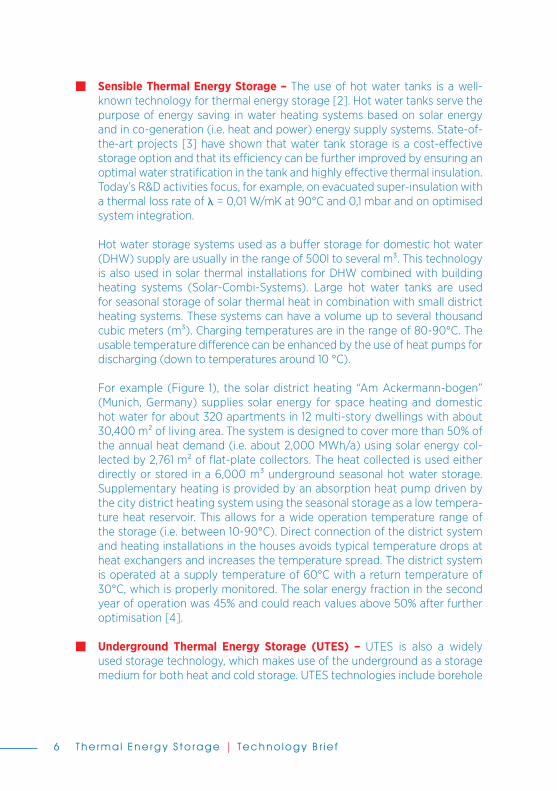
� Sensible Thermal Energy Storage – The use of hot water tanks is a well-known technology for thermal energy storage [2]. Hot water tanks serve the purpose of energy saving in water heating systems based on solar energy and in co-generation (i.e. heat and power) energy supply systems. State-of-the-art projects [3] have shown that water tank storage is a cost-eff ective storage option and that its effi ciency can be further improved by ensuring an optimal water stratifi cation in the tank and highly eff ective thermal insulation. Today’s R&D activities focus, for example, on evacuated super-insulation with a thermal loss rate of � = 0,01 W/mK at 90°C and 0,1 mbar and on optimised system integration.
Hot water storage systems used as a buff er storage for domestic hot water (DHW) supply are usually in the range of 500l to several m3. This technology is also used in solar thermal installations for DHW combined with building heating systems (Solar-Combi-Systems). Large hot water tanks are used for seasonal storage of solar thermal heat in combination with small district heating systems. These systems can have a volume up to several thousand cubic meters (m3). Charging temperatures are in the range of 80-90°C. The usable temperature diff erence can be enhanced by the use of heat pumps for discharging (down to temperatures around 10 °C).
For example (Figure 1), the solar district heating “Am Ackermann-bogen” (Munich, Germany) supplies solar energy for space heating and domestic hot water for about 320 apartments in 12 multi-story dwellings with about 30,400 m2 of living area. The system is designed to cover more than 50% of the annual heat demand (i.e. about 2,000 MWh/a) using solar energy col-lected by 2,761 m2 of fl at-plate collectors. The heat collected is used either directly or stored in a 6,000 m3 underground seasonal hot water storage. Supplementary heating is provided by an absorption heat pump driven by the city district heating system using the seasonal storage as a low tempera-ture heat reservoir. This allows for a wide operation temperature range of the storage (i.e. between 10-90°C). Direct connection of the district system and heating installations in the houses avoids typical temperature drops at heat exchangers and increases the temperature spread. The district system is operated at a supply temperature of 60°C with a return temperature of 30°C, which is properly monitored. The solar energy fraction in the second
year of operation was 45% and could reach values above 50% after further optimisation [4].
� Underground Thermal Energy Storage (UTES) – UTES is also a widely used storage technology, which makes use of the underground as a storage medium for both heat and cold storage. UTES technologies include borehole
12-30705_Thermal Energy Storage_Inhalt.indd 6 21.12.12 15:04

Thermal Energy Storage | Technology Br ief 7
storage, aquifer storage, cavern storage and pit storage. Which of these technologies is selected strongly depends on the local geological conditions.
Borehole storage is based on vertical heat exchangers installed underground, which ensure the transfer of thermal energy to and from the ground layers (e.g. clay, sand, rock). Many projects aim for seasonal storage of solar heat in summer to heat houses or offi ces in winter. Ground heat exchangers are also frequently used in combination with heat pumps where the ground heat exchanger extracts low-temperature heat from the soil.
Aquifer storage uses a natural underground water-permeable layer as a storage medium. The transfer of thermal energy is achieved by mass transfer (i.e. extracting/re-injecting water from/into the underground layer). Most
Table 1 – Typical Parameters of Thermal Energy Storage Systems [1]
TESSystem
Capa
city
(kW
h/t)
Pow
er
MW
)
Effi c
ienc
y (%
)
Stor
age
perio
d (h
, d, m
)
Cost
(€
/kW
h)
Sensible (hot water) 10-50 0.001-10 50-90 d/m 0.1-10PCM 50-150 0.001-1 75-90 h/m 10-50Chemical reactions 120-250 0.01-1 75-100 h/d 8-100
Figure 1 – Large Hot Water Storage (construction and fi nal state) combined with Solar Thermal District Heating “Am Ackermann-bogen”
in Munich, Germany
12-30705_Thermal Energy Storage_Inhalt.indd 7 21.12.12 15:04
Thermal Energy Storage | Technology Br ief8
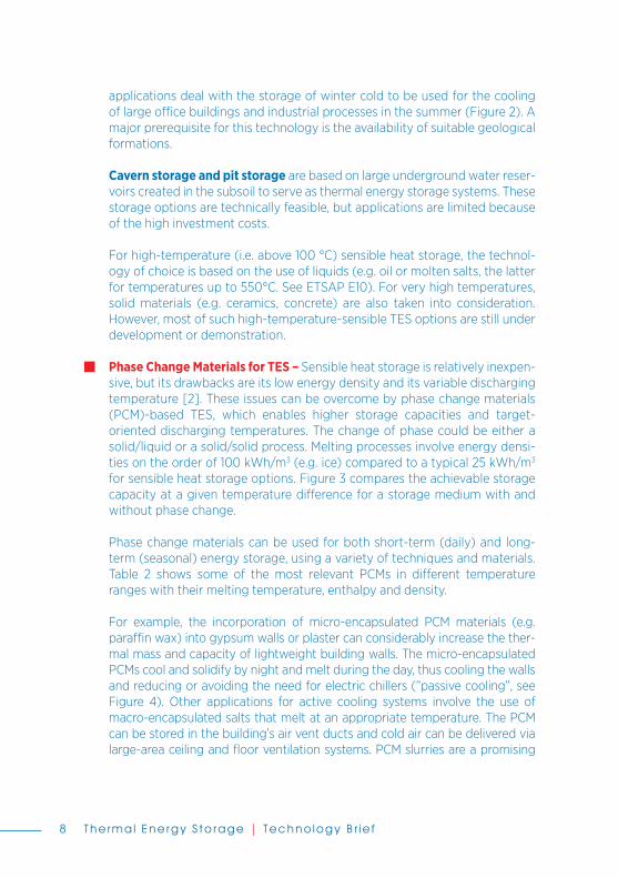
applications deal with the storage of winter cold to be used for the cooling of large offi ce buildings and industrial processes in the summer (Figure 2). A major prerequisite for this technology is the availability of suitable geological formations.
Cavern storage and pit storage are based on large underground water reser-voirs created in the subsoil to serve as thermal energy storage systems. These storage options are technically feasible, but applications are limited because of the high investment costs.
For high-temperature (i.e. above 100 °C) sensible heat storage, the technol-ogy of choice is based on the use of liquids (e.g. oil or molten salts, the latter for temperatures up to 550°C. See ETSAP E10). For very high temperatures, solid materials (e.g. ceramics, concrete) are also taken into consideration. However, most of such high-temperature-sensible TES options are still under development or demonstration.
� Phase Change Materials for TES – Sensible heat storage is relatively inexpen-sive, but its drawbacks are its low energy density and its variable discharging temperature [2]. These issues can be overcome by phase change materials (PCM)-based TES, which enables higher storage capacities and target-oriented discharging temperatures. The change of phase could be either a solid/liquid or a solid/solid process. Melting processes involve energy densi-ties on the order of 100 kWh/m3 (e.g. ice) compared to a typical 25 kWh/m3 for sensible heat storage options. Figure 3 compares the achievable storage capacity at a given temperature diff erence for a storage medium with and without phase change.
Phase change materials can be used for both short-term (daily) and long-term (seasonal) energy storage, using a variety of techniques and materials. Table 2 shows some of the most relevant PCMs in diff erent temperature ranges with their melting temperature, enthalpy and density.
For example, the incorporation of micro-encapsulated PCM materials (e.g. paraffi n wax) into gypsum walls or plaster can considerably increase the ther-mal mass and capacity of lightweight building walls. The micro-encapsulated PCMs cool and solidify by night and melt during the day, thus cooling the walls and reducing or avoiding the need for electric chillers (”passive cooling”, see Figure 4). Other applications for active cooling systems involve the use of macro-encapsulated salts that melt at an appropriate temperature. The PCM can be stored in the building’s air vent ducts and cold air can be delivered via large-area ceiling and fl oor ventilation systems. PCM slurries are a promising
12-30705_Thermal Energy Storage_Inhalt.indd 8 21.12.12 15:04

Thermal Energy Storage | Technology Br ief 9
Table 2 Thermal Storage PCM Properties
PCM Melting Temp., °C Melting Enthalpy, kJ/kg Density, g/cm3
Ice 0 333 0.92Na-acetate Trihydrate
58 250 1.3
Paraffi n -5 to 120 150-240 0.77Erytritol 118 340 1.3
Figure 2 – Layout Scheme of an Aquifer Storage System
Figure 3 – Stored Heat vs. Temperature for Sensible (without phase change) and Latent TES [4]
Figure 4 – Layout Scheme for “Passive Cooling”
Summer:Coolingof office buildings /industrialprocesses
Winter:Heatingof office buildings /industrialprocesses
12-30705_Thermal Energy Storage_Inhalt.indd 9 21.12.12 15:04

Thermal Energy Storage | Technology Br ief10
technology. For example, ice-slurries or water-paraffi n dispersions can be used for building or industrial cooling purposes. As slurries can be pumped, they can be used for either storing or distributing thermal energy.
A number of R&D activities, most of them aimed at industrial applications, currently focus on high-temperature PCM (above 150°C).
� Thermal Energy Storage via Chemical Reactions – High energy density (i.e. 300 kWh/m3) TES systems can be achieved using chemical reactions (e.g. thermo-chemical storage, TCS) [2]. Thermo-chemical reactions, such as ad-sorption (i.e. adhesion of a substance to the surface of another solid or liquid), can be used to store heat and cold, as well as to control humidity. Typical applications involve adsorption of water vapour to silica-gel or zeolites (i.e. micro-porous crystalline alumino-silicates). Of special importance for use in hot/humid climates or confi ned spaces with high humidity are open sorption systems based on lithium-chloride to cool water and on zeolites to control humidity. Figure 5 shows an example of thermal energy storage by an adsorp-tion process (e.g. water vapour on zeolite): during charging, water molecules are desorbed from the inner surface of the adsorbent. The TES remains in this state until water molecules can be adsorbed by the adsorbent and the TES is discharged again. Table 3 shows some of the sorption materials that are currently under investigation [6]. Interesting fi elds of application include waste heat utilisation. In this context, TCSs are able to store thermal energy with high effi ciency and to convert heat into cold (i.e. desiccant cooling) at the same time, which makes these systems very attractive.
The high storage capacity of sorption processes also allows thermal energy transportation. Figure 6 shows a schematic view of such a system. For exam-ple, an ongoing demonstration project utilises waste heat from an incinera-tion plant to be used at an industrial drying process. The sorption TES (using zeolite/water) is charged at 150°C, transported over seven kilometers and dis-charged at 180°C. Dry and hot air during discharging are directly integrated into the drying process. The higher discharging temperature is made possible because the enthalpy of the humid air from drying is converted into a tem-perature lift by the adsorption of water vapour. A pilot storage in a standard freight container containing 13 tonnes of zeolite, with a storage capacity of up to three MWh and a charging power of 500 kW, is currently on the road. The economic analysis shows that applications of mobile storage systems with more than 200 storage cycles per year allow the system to run with a fi nal cost of delivered heat of about €55/MWh. Of course, the distance between energy source and demand site, investment costs and energy capacity have a strong infl uence on the energy price [9].
12-30705_Thermal Energy Storage_Inhalt.indd 10 21.12.12 15:04

Thermal Energy Storage | Technology Br ief 11
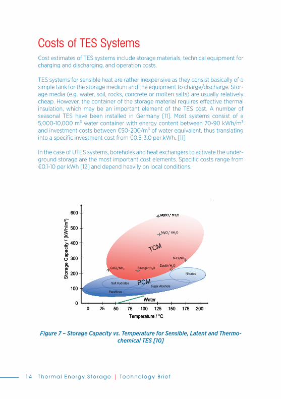
Table 4 lists some of the most interesting chemical reactions for thermal en-ergy storage [7, 8]. While sorption storages can only work up to temperatures of about 350°C, chemical reactions can go much higher. Figure 7 shows the diff erent TES technologies: sensible heat (i.e. water as an example); latent heat (i.e. diff erent materials); and thermo-chemical (i.e. sorption and chemi-cal reactions).
� Applications – Important fi elds of application for TES systems are in the building sector (e.g. domestic hot water, space heating, air-conditioning)
Table 3 – Sorption Materials under Investigation [6]
Material Example Developer
Microporous materials
Bindeless zeolite 13XBF, 4ABF Chemiewerke GermanyAlumino-phosphate
APO-CHANat. Institute of ChemistrySlovenia
Functional adsorbents
FAM-Z01FAM-Z02
MitsubishiJapan
Compositematerials
Selective water adsorbents
SWS-11CaCl2/silica
Boreskov InstituteRussia
Porous salt hydrates
MgSO4/MgCl2ECN (NL)Weimar Univ. Germany
Figure 5 – TES De/Adsorption Process
12-30705_Thermal Energy Storage_Inhalt.indd 11 21.12.12 15:04

Thermal Energy Storage | Technology Br ief12
and in the industrial sector (e.g. process heat and cold). TES systems can be installed as either centralised plants or distributed devices. Centralised plants are designed to store waste heat from large industrial processes, conventional power plants, combined heat and power plants and from renewable power plants, such as concentrated solar power (CSP). Their power capacity ranges typically from hundreds of kW to several MW (i.e. thermal power). Distributed devices are usually buff er storage systems to accumulate solar heat to be used for domestic and commercial buildings (e.g. hot water, heating, appli-ances). Distributed systems are mostly in the range of a few to tens of kW.
TES systems – either centralised or distributed - improve the energy effi ciency of industrial processes, residential energy uses and power plants by storing waste or by-product heat or renewable heat when it is available and supplying it upon demand. Thermo-chemical storage systems can also convert waste heat into higher temperature heat or into cold. A number of energy-intensive industrial sectors and processes (e.g. cement, iron and steel, glass) benefi t from TES systems. Manufacturing industry (e.g. automobile industry) can also benefi t signifi cantly from TES. Most importantly, TES can help integrate variable solar heat into the energy system. This applies either to short-term storage based on daily heat buff ers for domestic hot-water production or to long-term heat storage for residential and industrial heating purposes, based on large central storage systems and district heating networks.
TES systems can also help integrate renewable electricity from PV and wind. For example, the effi ciency of a (mechanical) compressed air energy storage (CAES) can be improved from about 50% to more than 70% by storing heat
WasteIncineration TCS
TCS
Truck and standardfreight container
DryingProcessTCS
ChargingTemperature150 °C
DischargingTemperature180 °C
Waste heat:3 MWh
Distance 10 km
Figure 6 – Mobile Sorption Storage System for Industrial Waste Heat Utilisation
12-30705_Thermal Energy Storage_Inhalt.indd 12 21.12.12 15:04

Thermal Energy Storage | Technology Br ief 13
during compression and discharging it to support expansion (see ETSAP E18). Charging a cold storage system using renewable electricity during high solar irradiation periods or wind peaks and delivering cold to consumers on demand is a further potential TES application.
Table 5 lists applications for centralised and distributed TES technologies, along with their contribution to energy effi ciency or to the integration of renewable energy.
12-30705_Thermal Energy Storage_Inhalt.indd 13 21.12.12 15:04
Thermal Energy Storage | Technology Br ief14
Costs of TES Systems Cost estimates of TES systems include storage materials, technical equipment for charging and discharging, and operation costs.
TES systems for sensible heat are rather inexpensive as they consist basically of a simple tank for the storage medium and the equipment to charge/discharge. Stor-age media (e.g. water, soil, rocks, concrete or molten salts) are usually relatively cheap. However, the container of the storage material requires eff ective thermal insulation, which may be an important element of the TES cost. A number of seasonal TES have been installed in Germany [11]. Most systems consist of a 5,000-10,000 m3 water container with energy content between 70-90 kWh/m3 and investment costs between €50-200/m3 of water equivalent, thus translating into a specifi c investment cost from €0.5-3.0 per kWh. [11]
In the case of UTES systems, boreholes and heat exchangers to activate the under-ground storage are the most important cost elements. Specifi c costs range from €0.1-10 per kWh [12] and depend heavily on local conditions.
0 25 50 75 100 125 150 175 200
100
200
300
400
500
600
Stor
age
Cap
acity
/ (kW
h/m
³)
Temperature / °C
0Water
PCMSalt Hydrates
Nitrates
Paraffines
Sugar Alcohols
TCMNiCl2NH3
CaCl2*NH3
MgSO4* 6H2O
Zeolith*H2OSilicagel*H2O
MgCl2* 6H2O
0 25 50 75 100 125 150 175 200
100
200
300
400
500
600
Stor
age
Cap
acity
/ (kW
h/m
³)
Temperature / °C
0WaterWater
PCMSalt Hydrates
Nitrates
Paraffines
Sugar AlcoholsPCMSalt Hydrates
Nitrates
Paraffines
PCMSalt Hydrates
Nitrates
Paraffines
PCMSalt Hydrates
Nitrates
Paraffines
Sugar Alcohols
TCMNiCl2NH3
CaCl2*NH3
MgSO4* 6H2O
Zeolith*H2OSilicagel*H2O
MgCl2* 6H2O
TCMNiCl2NH3
CaCl2*NH3
MgSO4* 6H2O
Zeolith*H2OSilicagel*H2O
MgCl2* 6H2O
Figure 7 – Storage Capacity vs. Temperature for Sensible, Latent and Thermo-chemical TES [10]
12-30705_Thermal Energy Storage_Inhalt.indd 14 21.12.12 15:04

Thermal Energy Storage | Technology Br ief 15
Phase change material (PCM) storage and thermo-chemical storage (TCS) sys-tems are signifi cantly more complex and expensive than the storage systems for sensible heat. In most cases (e.g. thermo-chemical reactors), they use enhanced heat and mass transfer technologies to achieve the required performance in terms of storage capacity and power, and the cost of the equipment is much higher than the cost for the storage material. In general, the cost of a PCM sys-tem ranges between €10-50 per kWh [12]. The cost of systems using expensive micro-encapsulated PCMs, which avoid the use of heat exchange surfaces, can be even higher. For example, the cost of complete plaster board (€17/kg) with micro-encapsulated paraffi n to be used as a passive cooling device within building structures (e.g. gypsum boards) includes the price of paraffi n (about €5/kg) and the micro-encapsulated material (€13/kg) [13].
The diff erence between the pure PCM and the complete TES system is even higher for active PCM installations. As an example, the costs of a calcium-chloride stor-age for the heat rejected from a thermally-driven absorption chiller includes [14] the cost of calcium-chloride, which is rather inexpensive (€0.3/kg) and the cost of a container, heat exchanger and other components that is around €65/kWh. Materials for thermo-chemical storage (TCS) are also expensive as they have to be prepared (e.g. pelletised or layered over supporting structures).
Also expensive are the containers and the auxiliary TCS equipment for both heat and mass transfer during energy charging and discharging. TCS systems can be operated as either open systems (i.e. basically packed beds of pellets at ambient
Table 4 – Most Interesting Chemical Reactions for Thermal Energy Storage [7, 8]
Reaction Temp. °C En. density,kJ/kg
Methane steam reforming CH4+H2O=CO+3H2 480-1195 6053Ammonia dissociation 2NH3=N2+3H2 400-500 3940Thermal dehydrogenation of metal hydrides
MgH2=Mg+H2 250-5003079 heat stor.9000 H2 stor.
Dehydration of metal hydroxides
CA(OH)2=CAO+H2O 402-572 1415
Catalytic dissociation SO3=SO2+ ½O2 520-960 1235
12-30705_Thermal Energy Storage_Inhalt.indd 15 21.12.12 15:04

Thermal Energy Storage | Technology Br ief16
Table 6 – Economic Viability of TES Systems as a Function of the Number of Storage Cycles per Year [15]
Cycles per year
5-yr energy savings,
kWh
5-yr economic savings,
€
Invest. cost
€/kWhSeasonal storage 1 500 25 0.25Daily storage 300 150,000 7500 75Short-term storage (3 c/day)
900 450,000 22,500 225
Buff er storage (10 c/day)
3,000 1,500,000 75,000 750
Table 5 – TES-relevant Applications
Application Technology Central/Distrib.
Energy Effi c./ Ren.
EnergyCold storage. (buildings)
PCM (ice, passive cooling) D EE + RE
Cold storage. (industry, appliances),
PCM (slurries) Absorption stor. (heat to cold)
D EE+RE
Domestic hot water (buff er storage)
Sensible storage (hot water) D RE
Heating (buildings, seasonal stor.)
Sensible stor. (UTES, large water tanks, district heating)
C RE
Process heat (indus-trial heating/drying, appliances)
Thermo-chem. storage. (sorption storage)
D EE+RE
Waste heat (cement, steel & glass industry)
Sensible stor. (solids), PCM, chem. reactions
C+D EE
High temp. storage (>400°C) for CSP & CAES
Sensible stor. (liquids, molten salt) PCM, chem.
reactionsC RE
pressure) or closed systems. Open systems are often the cheapest option while closed systems need sophisticated heat exchangers. The TCS cost ranges from €8-100 per kWh [12].
12-30705_Thermal Energy Storage_Inhalt.indd 16 21.12.12 15:04

Thermal Energy Storage | Technology Br ief 17
Table 7 – State of Development, Barriers and Main R&D Topics for Diff erent TES Technologies
Technology Status (%) Market/R&D
Barriers Main R&D topics
Sensible TESHot water tanks (buff ers)
95/5 Super insulation
Large water tanks (seasonal)
25/75 System integrationMaterial tank, stratifi cation
UTES 25/75Regulation, high cost,
low capacitySystem integration
High temp. solids 10/90 Cost, low capacity High temp materialsHigh temp. liquids 50/50 Cost, temp<400C Materials
PCM
Cold storage (ice) 90/10 Low temp.Ice
productionCold storage (other)
75/25 High cost Materials (slurries)
Passive cooling (buildings)
75/25High cost,
performanceMaterials
(encapulation)High temp. PCM (waste heat)
0/100High cost,
Mat.stabilityMaterials
(PCM containers)TCS
Adsorption TES 5/95 High cost, complexityMaterials, and reactor design
Aborption TES 5/95 High cost, complexityMaterials and reactor design
Other chemical reactions
5/95 High cost, complexityMaterials and reactor design
The overall economic evaluation of a TES system depends signifi cantly on the specifi c application and operation needs, including the number and frequency of storage cycles. This dependency is shown in Table 6 [15] where a simplifi ed calculation is based on a TES system with a 100-kWh storage capacity, a price of thermal energy of €0.05/kWh and an investment return time of fi ve years. The calculation focuses on the price of thermal energy and determines the cost range for TES to be economically competitive based on today’s energy prices. Table 6
12-30705_Thermal Energy Storage_Inhalt.indd 17 21.12.12 15:04

Thermal Energy Storage | Technology Br ief18
shows that, for seasonal storage, with one cycle per year, the energy saving over fi ve years amounts to just €25, which leads to a maximum (aff ordable) specifi c investment cost of €0.25/kWh. This cost can only be viable using a cheap sensible heat TES system (i.e. basically a large water tank). PCM and TCS systems, which are in general much more expensive, are economically viable only for applications with a higher number of cycles. For applications with more than 1,000 cycles per year, the viable investment cost is higher than €250/kWh.
Potential and Barriers TES technologies face some barriers to market entry and cost is a key issue. Other barriers relate to material properties and stability, in particular for TCS. Each stor-age application needs a specifi c TES design to fi t specifi c boundary conditions and requirements. R&D activities focus on all TES technologies. Most of such R&D eff orts deal with materials (i.e. storage media for diff erent temperature ranges), containers and thermal insulation development. More complex systems (i.e. PCM, TCS) require R&D eff orts to improve reacting materials, as well as a better under-standing of system integration and process parameters (Table 7).
TES market development and penetration varies considerably, depending on the application fi elds and regions. Penetration in the building sector is comparably slow in Europe where the construction of new buildings is around 1.3% per year and the renovation rate is around 1.5%; of course, the integration of TES systems is easier during construction. The estimate of the European potential is based on a 5% implementation rate of TES systems in buildings [16]. Penetration could be much higher in emerging economies with their high rates of new building con-struction.
TES potential for co-generation and district heating in Europe is also associated with the building stock. The implementation rate of co-generation is 10.2% [17], while the implementation of TES in these systems is assumed to be 15%. As far as TES for power applications is concerned, a driving sector is the concentrating solar power (CSP) where almost all new power plants in operation or under construc-tion are equipped with TES systems, mostly based on molten salt. This is perhaps the most important development fi led for large, centralised TES installations [18]. In the industrial sector, about 5% of the fi nal energy consumption is assumed to be used by TES installations. In particular, the use of industrial waste heat is expected to grow since the price of fossil fuels will rise and energy effi ciency will be the key
12-30705_Thermal Energy Storage_Inhalt.indd 18 21.12.12 15:04

Thermal Energy Storage | Technology Br ief 19
to competitiveness. Based on the University of Lleida study [16], the expansion of TES technologies is expected to be signifi cant in Europe and Asia (particularly Japan) and somewhat lower (50%) in the United States. The global potential is estimated at approximately three times the European potential.
References and Further Information1. Hauer, A., Storage Technology Issues and Opportunities, Committee on Energy Re-
search and Technology (International Energy Agency), International Low-Carbon Energy Technology Platform, Strategic and Cross-Cutting Workshop “Energy Stor-age – Issues and Opportunities”, 15 February 2011, Paris. France.
2. Energy Conservation through Energy Storage (ECES) Programme, International Energy Agency, Brochure: http://www.iea-eces.org/fi les/090525_broschuere_eces.pdf.
3. ECES homepage: http://www.iea-eces.org/.
4. Reuss, M., Solar District Heating in Germany – Findings and Prospects, Proceed-ings of the ISES Solar World Congress 2011, 28 August – 2 September 2011, Kassel, Germany.
5. Günther, E., H. Mehling, S. Hiebler, Measurement of the Enthalpy of PCM, Proceed-ings of Eff stock 2009 – 11th International Conference on Thermal Energy Storage, 2009, Stockholm, Sweden.
6. Hauer, A., Thermochemical Energy Storage Systems, CIMTEC, 5th Forum on New Materials, June 2006, Montecatini Italy.
7. Garg, H.P. et al., Solar Thermal Energy Storage, D. Reidel Publishing Company, Dordrecht/Boston/Lancaster, 1985, ISBN 90-277-1930-6.
8. Bogdanovic, A., B. Ritter, Spliethoff , Active MgH2-Mg systems for reversible chemical energy storage, Angewandte Chemie (International Edition), Vol. 29, Nr. 3, pages 223 – 328.
9. Kroenauer, A., E. Laevemann, A. Hauer, Mobile Sorption Heat Storage in Industrial Waste Heat Recovery, International Conference on Energy Storage, InnoStock 2012, May 2012, Lleida, Spain.
10. Laevemann, E., Thermische Energiespeicher, Theoretische Grenzen und Beur-teilungskriterien, Experten-Workshop „Thermische Speicher: Potentiale und Gren-zen der Steigerung der Energiespeicherdichten“, DFG/PTJ, Berlin, June 2010, Berlin, Germany.
11. Solites, Solare Nahwärme und Langzeit-Wärmespeicherung – wissenschaftlich-technische Programmbegleitung für Solarthermie 2000 Plus, Final report of R&D project 0329607L, German Federal Ministry of Environment BMU, November 2007.
12-30705_Thermal Energy Storage_Inhalt.indd 19 21.12.12 15:04

Thermal Energy Storage | Technology Br ief20
12. Hauer, A., Energiespeicherung und Netzmanagement, FVEE-Jahrestagung 2010: „Forschung für das Zeitalter der erneuerbaren Energien“, October 2010, Berlin, Germany.
13. Price information by BASF and Maxit, 2009.
14. Helm, M., C. Keil, S. Hiebler, H. Mehling, C. Schweigler, Solar heating and cooling system with absorption chiller and low temperature latent heat storage: Energetic performance and operational experience, International Journal of Refrigeration, Volume 32, Issue 4, Pages 596-606, June 2009.
15. Tamme, R., Hochtemperaturwärmespeicherung für effi zientes Wärmemanage-ment in Industrie und Kraftwerkstechnik, ProcessNet-Jahrestagung 2010, Aachen, Germany.
16. Arce, P., L. F. Cabeza, M. Medrano, GREA – Report: Potential of Energy & CO2 Sav-ings due to the Use of Thermal Energy Storage. A Continental Overview – Europe, Universitat de Lleida, 2010.
17. Hendel-Blackford, S., T. Angelini and S. Ozawa, Energy Effi ciency in Lifestyles: Eu-rope and Japan, EU-Japan Centre for Industrial Cooperation, Final report, Report Number PECSGB0731212007.
18. International Energy Agency (IEA), Energy Technology Perspectives 2008, 2008, Paris, France.
Tabl
e 8
– Su
mm
ary
Tabl
e: K
ey D
ata
and
Figu
res
for T
herm
al S
tora
ge T
echn
olog
ies
Tech
nica
l per
form
ance
Typi
cal c
urre
nt in
tern
atio
nal v
alue
s an
d ra
nges
Ener
gy In
put/
Out
put
Sola
r hea
t, w
aste
hea
t, va
riabl
e re
new
able
ene
rgy
sour
ces
(PV,
win
d),
elec
tric
ity/h
eat
Tech
nolo
gy V
aria
nts
Sens
ible
The
rmal
Ene
rgy
Stor
age,
STE
SSt
orag
e in
Pha
se C
hang
e M
ater
ials
, PCM
Ther
mo-
chem
ical
Ene
rgy
Stor
age,
TCS
Stor
age
Cap
acity
(kW
h/t)
10 -
50
50 -
150
120
- 2
50Th
erm
al P
ower
(M
W)
0.0
01 -
100
.00
1 - 1
0.0
1 - 1
Effi c
ienc
y, %
50 -
90
75 -
90
75 -1
00
St
orag
e Pe
riod
(h,d
,w,m
)d
- y
h -
wh
- d
Cos
t (€
/kW
h)0
.1 -
10ot
t-50
8 -
100
Tech
nica
l life
time,
yr
10-3
0+
(dep
endi
ng o
n st
orag
e cy
cles
, tem
pera
ture
and
ope
ratin
g co
nditi
ons)
Load
(cap
acity
) fa
ctor
, %
8080
55M
ax. (
plan
t) a
vaila
bilit
y, %
95
9595
Typi
cal (
capa
city
) si
ze, M
We
250
.510
0In
stal
led
capa
city
, GW
e (GW
th)
9–10
(al
l typ
es)
<<1
18 (e
stim
ate)
Envi
ronm
enta
l Im
pact
Neg
ligib
le, w
ith G
HG
em
issi
ons
redu
ctio
n, d
epen
ding
on
the
amou
nt o
f prim
ary
foss
il en
ergy
sav
ed b
y us
ing
ener
gy s
tora
ge
Cost
s (U
SD 2
00
8)
Typi
cal c
urre
nt in
tern
atio
nal v
alue
s an
d ra
nges
Inve
stm
ent c
ost,
$/kW
340
0 –
450
060
00
– 15
,00
010
00
– 3
00
0O
&M
cos
t (fi x
ed &
var
iabl
e), $
/kW
/a12
025
020
– 6
0Fu
el c
ost,
$/M
Wh
N/A
N/A
N/A
Econ
omic
life
time,
yr
20To
tal p
rodu
ctio
n co
st, $
/MW
h80
– 11
012
0 –
30
025
– 7
5M
arke
t sha
re, %
0.2
5N
eglig
ible
N/A
12-30705_Thermal Energy Storage_Inhalt.indd 20 21.12.12 15:04

DisclaimerThe designations employed and the presentation of materials herein do not imply the expression of any opinion whatsoever on the part of the Sec-retariat of the International Renewable Energy Agency concerning the le-gal status of any country, territory, city or area or of its authorities, or con-cerning the delimitation of its frontiers or boundaries. The term “country” as used in this material also refers, as appropriate, to territories or areas.

The preparation of the paper was led byAndreas Hauer (ZAE Bayern).
Comments are welcome and should be addressed toRuud Kempener ([email protected]),Giorgio Simbolotti ([email protected]) and Giancarlo Tosato ([email protected])