thermal insulation from wood for … insulation from wood for buildings: effects of moisture and its...
TRANSCRIPT
U.S.D.A. FOREST SERVICE RESEARCH PAPER FPL 86 JULY 1968
U.S. DEPARTMENT OF AGRICULTURE FOREST SERVICE FOREST PRODUCTS LABORATORY MADISON, WIS.
THERMAL INSULATION FROM WOOD FOR BUILDINGS: EFFECTS OF MOISTURE AND ITS CONTROL
ABSTRACT
Thermal insulation is an important component of modern homes and other buildings. It provides for the comfort required for livability and, when properly designed for and installed, pays �or itself in fuel savings during winter heating and power savings during summer cooling.
Various kinds of thermal insulation made from wood are described. Considerations required for proper design are discussed. Design values for wood and wood-base materials are presented. Methods are presented for estimating heat flow, fuel savings, and temperatures on surfaces and within typical constructions. The effects of moisture as influenced by insulation and cold weather are discussed. Proper vapor barrier practice for good results are presented.
This Paper is a revision of U.S. Forest Products Laboratory Report 1740, “Thermal Insulation Made of Wood-Base Materials--Its Application and Use in Houses, ” originally prepared by L. V. Teesdale in 1949.
FOREWORD
Wood and wood-base materials are by nature relatively good heat insulators. The natural fiber of wood is in itself a hollow cell which provides a minute air space, hence an insulating unit. Thermal insulations, usually considered to be materials with a unit conductivity of less than are frequently made from wood and wood fiber.
The need for factual information on the heat flow factors of materials is more important today because of higher fuel and power costs for winter heat-ing and summer cooling (air conditioning), greater overall comfort demands by the user, and the cost of the equipment needed to maintain this desired comfort.
The Forest Products Laboratory, during the course of its engineering investi-gations and allied studies extending over the past 57 years, has obtained much basic information on the thermal insulation of wood and wood-base materials, including their influence on fuel economy, comfort of occupants, attic ventilation, vapor barriers, and cold weather condensation. It is the purpose of this publica-tion to present such information, together with procedures necessary for calculating the thickness of insulation required for a specified installation and the influence of the other components of a building. The fullest efficiency to be derived from the use of insulation, as with any material, is in large part dependent on how it is used. The selection of the wrong materials, the use of improper thicknesses of materials, or faulty installation methods can constitute a severe drain on the owner’s income as well as on the Nation’s resources.
This publication is intended to aid in independent judgment regarding insula-tion. To prudent buyers, a knowledge of the fact that they are using insulation is insufficient. Accordingly, this publication aims to assist in a careful estima-tion of where, when, and why insulation is needed; to show how the different wood-base materials meet specific requirements; and to emphasize some of the principles frequently overlooked that should be followed in the proper installa-tion of insulation.
CONTENTS
Page
Introduction . . . . . . . . . . . . . . . . . . . . . . . . . . . . . . . . . . Fundamentals for heating and cooling . . . . . . . . . . . . . . . . . . .
Methods of heat transfer . . . . . . . . . . . . . . . . . . . . . . . . . Thermal properties of materials . . . . . . . . . . . . . . . . . . . . . Method of computing thermal conductivities . . . . . . . . . . . . . . . Type of window . . . . . . . . . . . . . . . . . . . . . . . . . . . . . . Inside surface temperatures . . . . . . . . . . . . . . . . . . . . . . .
Why insulate and where . . . . . . . . . . . . . . . . . . . . . . . . . . . Influence of insulation on comfort . . . . . . . . . . . . . . . . . . . . Relation of climate to insulation . . . . . . . . . . . . . . . . . . . . . Insulation requirements . . . . . . . . . . . . . . . . . . . . . . . . . . Using tables of calculated coefficients of transmission . . . . . . . . Where to insulate . . . . . . . . . . . . . . . . . . . . . . . . . . . . . Reducing heat loss in existing buildings . . . . . . . . . . . . . . . . . Fuel savings from insulation . . . . . . . . . . . . . . . . . . . . . . . Influence of insulation on dirt pattern development . . . . . . . . . . .
Wood and wood-base insulations . . . . . . . . . . . . . . . . . . . . . . Rigid insulation . . . . . . . . . . . . . . . . . . . . . . . . . . . . . . Flexible insulation . . . . . . . . . . . . . . . . . . . . . . . . . . . . . Fill insulation . . . . . . . . . . . . . . . . . . . . . . . . . . . . . . . Reflective insulation . . . . . . . . . . . . . . . . . . . . . . . . . . . . Miscellaneous insulating materials . . . . . . . . . . . . . . . . . . . .
Cold weather and other condensation as influenced by insulation . . . . Condensation within walls and roofs . . . . . . . . . . . . . . . . . . . Effect of insulation on condensation . . . . . . . . . . . . . . . . . . . Vapor pressure-permeability relationships . . . . . . . . . . . . . . . Vapor barriers . . . . . . . . . . . . . . . . . . . . . . . . . . . . . . Ventilation in attics and roofs . . . . . . . . . . . . . . . . . . . . . . Crawl space condensation control . . . . . . . . . . . . . . . . . . . . Condensation on interior wall surfaces . . . . . . . . . . . . . . . . . Effect of humidity on comfort and health . . . . . . . . . . . . . . . .
1 2 2 3
10 14 14 16 16
17 20 20 22 23 25 26 26 28 28 28 29 29 29 32 33 35 37 39 41 41
FPL 86 ii
THERMAL INSULATION FROM WOOD FOR BUILDINGS:
EFFECTS OF MOISTURE AND ITS CONTROL
By W A Y N E C. LEWIS, Engineer
Forest Products Laboratory 1
Forest Service U.S. Department of Agriculture
INTRODUCTION
One of the most important developments in modern construction practices is the use of ther-mal insulation in all types of buildings and partic-ularly in the intermediate and low-cost dwellings. Comfort is the basic objective establishing the need for insulation, but fuel and power economy may often be the factors justifying the added first cost involved in applying insulation. During cold weather, houses must be heated to maintain com-fortable indoor temperatures, and insulation plays an important part in obtaining the uniformity of temperature that establishes comfortable condi-tions. During hot weather, insulation helps to keep indoor temperatures cooler than they would be in an uninsulated building.
Even these advantages would not necessarily justify the use of insulation were it not for the fact that in cold climates there is a material saving in fuel, smaller heating plants can be used, and cleaning and decorating expense may be reduced; where summer conditioning is used, the power savings will further offset the cost of
added thermal insulation. These savings will in themselves return the added cost of the insulation in a relatively short time.
Materials used in construction are selected to suit the needs of the service they are expected to perform. For example, in a conventional frame wall, the exterior may be wood sidingover wood or insulating board sheathing fastened to the studs, which act as structural supports for the wall. The inner wall surface may be gypsum lath and plaster or other suitable wall covering. All these materials offer resistance to the trans-mission of heat from one side to the other, and the heat transmission is proportional to the dif-ferences in temperature on opposite sides of the wall. Stucco or brick or stone veneer may be used in place of wood for exterior wall covering. Other materials may also be used for walls, such as brick, tile, concrete blocks, or stone, with the interior surface furred, lathed, and plastered. Such walls, as commonly constructed in the usual thicknesses, will transmit more heat than will conventional frame walls. Where pre-fabricated construction is used, the wall panels may be made of light framing members covered
1Maintained at Madison, Wis., in cooperation with the University of Wisconsin.

on both sides with plywood or other suitable materials.
The heat transfer through any of the wall types described can be reduced by increasing the thick-ness of the basic materials. For example, two thicknesses of wood sheathing could be used in place of the one thickness generally used, or the thickness of a masonry wall could be increased above that required for minimum strength. Gen-erally speaking, however, this means of decreas-ing heat loss is expensive without being very effective, and there are better means of accom-plishing the desired purpose.
The materials used in construction are gener-ally selected on a basis of initial cost, availabil-ity, building code requirements, appearance, fire hazard, and similar factors. In some cases, the materials may be selected because they are more resistive to heat transfer than others. For example, insulating board products may be used in place of wood sheathing, as wall or ceiling surfacing materials, or in some applications as sound-deadening material in the wall or floor system where the thermal resistance is an added factor.
Structural and finish materials vary widely in thermal properties. Wood is much more resistive to heat transmission than is masonry. In this respect, 1 inch of Douglas-fir is equal in resist-ance to heat transmission to about 12 inches of concrete or stone, but it would take about 2 inches of the wood to equal 1 inch of insulating board.
FUNDAMENTALS FOR HEATING AND COOLING
Methods of Heat Transfer
Heat seeks to attain a balance with the sur-rounding conditions, just as water will flow from a high to a low level or gases will flow from a high- to a low-pressure area. When outside tem-peratures are low, heat is supplied in houses and other similarly occupied buildings to main-tain the inside temperatures in the comfort range. Under such conditions, with a difference in tem-perature between the inside and outside, there will be a transfer of heat through the walls, floors, ceiling, and through windows and doors at
a rate that bears some relation to the tempera-ture differences and to the resistance to heat flow of intervening materials. To maintain a con-stant inside temperature when outside tempera-tures are constant and below inside temperatures will require a constant supply of heat, and the heat supply or inflow in this case equals the heat loss or outflow. The amount of heat required at any fixed temperature depends upon the rate that the heat will be transmitted through intervening materials used on the construction of the enclos-ing units.
The transfer of heat may take place by one or more of three methods--conduction, convection, and radiation (fig. 1).
Heat is transmitted through solid materials by conduction. In a steam-heated radiator, the steam heats the inner surface of the radiator walls, and this heat flows through the walls to the outer sur-face by conduction.
Heat transfer by convection applies to heat carried by air currents from a warm zone to a cold zone. Air in contact with the warm outer surface of a radiator becomes heated above the temperature of the surrounding atmosphere, and rises, being replaced by colder air. Thus a cir-culation of air over the heated surface carries heat from the radiator to raise the temperature of the surrounding atmosphere.
Heat may be transmitted from a warm body to a cold one by wave motion through space; the process is called radiation, as it represents radiant energy. The waves do not heat the space through which they move, but when they come in contact with a colder surface or object, a part of the radiant energy is absorbed and converted into heat and part is reflected. For example, when one is standing near a radiator or an open fire, those surfaces of the body toward the source of heat are warmed by radiation and those surfaces away from the source of heat do not feel the radiant heat. The air temperature would be essen-tially the same in both types of exposure.
Heat transfer through a structural unit com-posed of a variety of materials may include any one or more of the three methods described. In the case of a frame house having anexterior wall consisting of plaster, gypsum lath, 2- by 4-inch studs placed 16 inches on centers, 3/4-inch wood sheathing, sheathing paper, and bevel siding, heat is transferred from the room atmosphere to the plaster by radiation and convection, and through the lath and plaster by conduction. Heat
FPL 86 2

ZM 83284 F
Figure 1.--Methods of heat transfer transfer across the stud space is by radiation from the back of the lath to the colder sheathing and by convection, since the air warmed by the lath moves upward on the warm side of the stud space and air cooled by the sheathing moves downward on the cold side, Heat transfer through the sheathing, sheathing paper, and siding will be by conduction. Some minor air spaces will be found behind bevel siding, and the heat transfer across these spaces will be principally by radia-tion. The heat transfer through the studs from the lath to the sheathing will be by conduction. The heat transfer from the outer surface of the wall to the atmosphere will be principally by convection and radiation. The movement of air on the outside (wind) will increase this convective loss.
Heat transfer by radiation across an air space is affected by the character of both of the sur-faces. A dull black body or surface absorbs all the radiant waves that strike it but other types of surface reflect some part of the radiant heat. In general, bright metallic surfaces have high reflective properties, whereas most nonmetallic materials used in building construction have low reflective properties.
The emission of radiant heat from a surface, emissivity, is in direct proportion to the amount of absorption. The transfer of heat by radiation across an air space is affected by the emissivity of the boundary surfaces.
Thermal Properties of Materials
When it is necessary to calculatethe air-to-air heat transmission factor (U) for a given combi-nation of building materials with greatest accu-racy, tests would be made on full-sized panels of the construction unit represented in a guarded hot box. Few research organizations are equipped to make hot-box tests, and the tests are expen-sive. It would hardly be practical to make tests on all combinations of construction and insulation that may occur in buildings. Nevertheless, for design purposes there is need for a simple and practical method of determining U values of con-struction assemblies so that the thermal prop-erties of different combinations of construction and insulation may be compared, and estimates made of the total amount of heat capacity needed
3
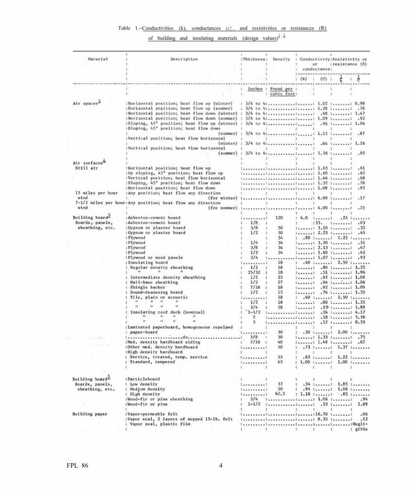
Table 1.--Conductivities (k), conductances and resistivities or resistances (R)
of building and insulating materials (design values)1 , 2
FPL 86 4
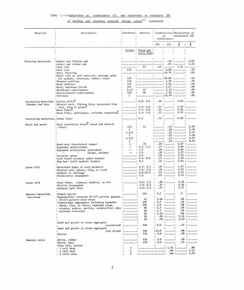
Table 1.--Conductivities conductances (C), and resistivities or resistances (R)
of building and insulating materials (design values)1, 2
(continued)
5

Table 1.--Conductivities (k), conductances (C), and resistivities o r resistances (R)
of building and insulating materials (design values)1,2
(continued)
FPL 86 6

Table 1. --Conductivities (k), conductances and resistivities or resistances
of building and insulating materials (design values)1 , 2
(continued)
(size of heating unit) and radiation or equivalent required for various in a building.
Tests have been made and coefficients of heat transmission have been established for the usual materials used in construction or for insulating materials. Materials of a homogenous character, such as wood, fiberboard, fiberous insulation and similar materials, are generally tested by the hot-plate method, but of irregular shape, such as concrete block and hollow tile, are tested by the guarded-box method. By proper use of the coefficients established for the various materials used in a construction assembly, the overall U value can be estimated by calculation. The results obtained by calculation agree reason-ably well with those obtained by test in the guarded hot box.
The standard test procedure by the hot-plate method requires that the test material be oven-dried. Therefore the conductivity values as given in most tables are based on dry material. Under service conditions, some building materials may contain moisture, and the moisture may affect the overall heat transmission. For most design purposes, however, the U values obtained by computation based on dry materials will be sufficiently accurate.
Values recommended for use in computing the thermal properties of building units are given in table 1. Values that may be used for reflective
insulation are given in table 2. The Forest Products Laboratory has made
careful determinations of the thermal conductivity of wood at various values of moisture content. These tests furnished sufficient data on the relationship between conductivity, specific grav-ity, and moisture content to make it possible to compute the approximate thermal conductivity across the grain for any wood for which the specific gravity is known and for which the mois-ture content can be determined or assumed.
Unit heat conductivity, represented by the symbol k, is defined as the amount of heat in British thermal units that will pass in 1 hour through 1 square foot of material 1 inch thick per 1° F. temperature difference between faces of the material. This unit is expressed as B.t.u. inch per hour square foot degree F.
Table 3 gives the average specific gravity of ovendry specimens of many commercial species of wood in the United States, and the k value at 0 percent moisture content. Also given are the R value per inch of thickness and the R value for material 3/4 inch thick. R is the resistance to heat flow, which is the reciprocal of conductivity, or conductance.
For some purposes, the calculated thermal properties of materials should be based on the moisture content attained in service. The thermal conductivity of a given wood at a known or
7

assumed moisture content can be determined from figure 2. To use this chart, obtain the average specific gravity from table 3 for the wood under consideration. Determine or assume the moisture content of the wood. When the actual moisture content is not known, assume it is
15 percent for wood siding or sheathing and 7 percent for inside woodwork or finish. On the chart, find the moisture content of the wood and follow the vertical line upward until it intersects the sloping line that corresponds to the specific gravity of the wood. The reading on the vertical
Figure 2.--Relation between computed conductivity and moisture content for wood having different specific gravity values. (Specific gravity based on volume at current mois-ture content and weight when ovendry. Conductivity computed from formula K = S [1.39 + 0.028M] + 0.165.) ZM 38147 F
FPL 86 8

scale at the left of this intersection point is the desired thermal conductivity, k, for the wood at the assumed moisture content.
The specific gravity data of table 3 are average values for the species listed. There are, of course, appreciable variations in specific gravity between boards and even between shipments of the same species. Infiltrated substance, such as gums and resins, and such defects as checks, knots and irregular grain may also influence conductivity, but for purpose of calculation, those factors may be ignored.
The conductivity value for plywood is essen-tially the same as that for solid wood of the same thickness.
Values for corrugated paper of the type devel-oped at the Forest Products Laboratory for use as core stock in sandwich construction are given in table 4. Corrugated paper products with vari-ous combinations of surfacing materials and of different thicknesses are also among the mater-ials used as insulation in conventional frame
construction. These data are based on paper treated with 15 percent of water-soluble phenolic resin before the paper was corrugated with “A” flute rolls. Figure 3 shows a number of different methods of assembling, some with flutes parallel with the covering faces, some with flutes per-pendicular, some with simple cells with the nodes of opposing corrugations in contact, and others with an between corrugated sheets. As made, there are about 3-1/2 corrugations per inch. The k value applies to the corrugated material without the covering sheet of plywood shown.
In table 5 are given the effects of foamed resin and fill insulation on thermal properties of honeycomb cores.
The Forest Products Laboratory has also determined that the thermal conductivity of the other wood-base panel materials can be estimated on the basis of the density of the particleboard or building fiberboard.2 Values of typical products are presented in table 1 for use in design.
Table 2.--Approximate thermal conductance and resistance values 1for reflective surfaces with air space
2Lewis, Wayne C. Thermal Conductivity of Wood-Base Fiber and Particle Panel Materials. U.S. Forest Service Research Paper FPL 77, Forest Products Laboratory, June 1967.
9
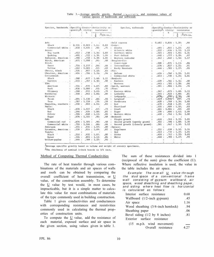
Table 3.--Average specific gravity, thermal and resistance values of various species of hardwoods and softwoods
Method of Computing Thermal Conductivities
The rate of heat transfer through various com-binations of the materials and air spaces of walls and roofs can be obtained by comparing the overall coefficient of heat transmission, or U value, of the construction assembly. To determine the U value by test would, in most cases, be impracticable, but it is a simple matter to calcu-late this value for most combinations of materials of the type commonly used in building construction.
Table 1 gives conductivities and conductances with corresponding resistances and resistivities commonly used in calculating the thermal prop-erties of construction units.
To compute the U value, add the resistance of each material, exposed surface and air space in the given section, using values given in table 1.
The sum of these resistances divided into 1 (reciprocal of the sum) gives the coefficient (U). Where reflective insulation is used, the value in the table includes the air space.
Example: The overall U value through the stud space of a conventional frame wall consisting of gypsum wallboard, air space, wood sheathing and sheathing paper, and siding where heat flow is horizontal is calculated as follows:
Interior surface resistance Wallboard (1/2-inch gypsum) Air space Wood sheathing (3/4-inch hemlock) Sheathing paper Bevel siding (1/2 by 8 inches) Exterior surface resistance
(15 m.p.h. wind movement) Overall resistance
0.68 .45
1.16 .94 .06 .81
.17 4.27
FPL 86 10

Table 4.--Thermal conductivity of honeycomb cores with
no fill insulation1
Figure 3.--Various types of corrugated-paper honeycomb cores. ZM 92877 F
11
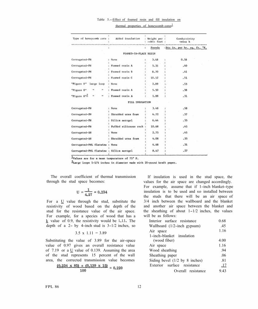
Table 5.--Effect of foamed resin and fill insulation on
thermal properties of honeycomb cores1
The overall coefficient of thermal transmission If insulation is used in the stud space, the through the stud space becomes: values for the air space are changed accordingly.
For example, assume that if 1-inch blanket-type insulation is to be used and so installed between the studs that there will be an air space of
For a U value through the stud, substitute the 3/4 inch between the wallboard and the blanket resistivity of wood based on the depth of the and another air space between the blanket and stud for the resistance value of the air space. the sheathing of about 1-1/2 inches, the values For example, for a species of wood that has a will be as follows: k value of 0.9, the resistivity would be The Interior surface resistance 0.68 depth of a 2- by 4-inch stud is 3-1/2 inches, so Wallboard (1/2-inch gypsum) .45
3.5 x 1.11 = 3.89 Air space 1-inch-blanket insulation
1.16
Substituting the value of 3.89 for the air-space (wood fiber) 4.00 value of 0.97 gives an overall resistance value Air space 1.16 of 7.19 or a U value of 0.139. Assuming the area Wood sheathing .94 of the stud represents 15 percent of the wall Sheathing paper .06 area, the corrected transmission value becomes Siding bevel (1/2 by 8 inches) .81
Exterior surface resistance .17 Overall resistance 9.43
FPL 86 12
Gypsum board ceiling (1/2 inch) .45 .45
The U value for the stud space and stud would be
Where regular-density insulating board sheath-ing is used in place of wood sheathing, the com-putation through the stud space would be made as follows:
Interior surface resistance 0.68 Wallboard (1/2-inch gypsum) .45 Air space 1.16 Insulation sheathing (25/32 inch) 1.96 Wood siding, bevel (1/2 by 8 inches) .81 Exterior surface resistance .17
Overall resistance 5.23
1 u = - = 0.1915.23
The U value for the stud and stud space would be
The application of the formula for heat trans-mission to top floor ceilings is done in the same manner as for side walls, but the coefficients used for surface and air space resistances depend upon the direction of heat flow,
If insulation is used, there should be provision for ventilation between the insulation and roof sheathing. In computing heat flow, the roof sheathing, roofing, and exterior surface resist-ances are not included, but the resistance value used for the air space between the insulation and roof sheathing is the same as that used for a closed air space.
For a flat deck having a composition roof, wood sheathing, 10-inch-roof joist with a 2-inch blanket set between the joists, with an air space above and below the insulation, and with a ceiling of 1/2-inch gypsum hoard, the computation would be as follows:
Heat flow up Heat flow down Winter Summer
Interior surface resistance 0.61 0.92
Air space (3/4 inch) .98 .92 Blanket insulation
(2 x 3.70) 7.40 7.40 Air space (6 inches) .98 .92
Overall resistance 10.42 10.61
The difference in overall U value between heat flow up and heat flow down is not significant in the case of insulated roofs where poured, rigid,
or batt insulation is used, and the U value is 0.15 or lower. It is significant where higher values occur, If the covering sheet of the insulation facing the 3/4-inch air space were of a reflective material having an effective emissivity value of 0.05, the R value 2.00 (see table 2) could be substituted for the R value 0.98 for heat flow up, changing the U value from
to For heat flow down, the R value of 0.92 for the 3/4-inch air space would be changed to 4.8, changing the U value to
The method of computing the U value for floors over unheated crawl spaces in basement-less houses is the same as that used for roofs; that is, the values set up for heat flow down are used. The surface resistance value for the sur-face facing the crawl space would be that used for still air (0.92). For concrete slab floors laid on the ground, heat is transmitted through the floor to the ground below and from the ground
the slab through the foundation wall to the ground outside. The heat transfer through the floor to the ground is not uniform over the whole area, greatest near the outside walls. Heat is also transmitted through the slab to the founda-tion wall and to the outside both above and below grade. Accurate methods of determining the heat transfer are very involved and beyond the scope of this presentation. Tests made by the National Bureau of Standards on concrete slab floors (reference BMS 103) have shown that the heat loss may be calculated as proportional to the linear length of the exposed edge rather than total floor area, and that insulation the floor and the foundation wall around the perim-eter of the building will reduce the heat loss at this point very appreciably.
The heat loss through doors and windows is
generally much greater than that through walls, ceilings, or floors. The coefficients of trans-mission values) generally used for doors are given in table 6.
Table 6.--Coefficients of themal transmission (U) through solid core flush doors of dif-ferent thicknesses with and with-out wood storm doors
These values are for solid doors of the thick-ness indicated and glazed storm doors. The losses of heat through doors having glass or wood panels can be computed, assuming a U value of 1.13 for glass or thin wood panels.
The values commonly used for windows in vertical position are:
Type of Window3
Single window 1.13 Double (storm sash) .56 Double glazing (2 thicknesses
of glass 1/4 inch apart) .65 Glass blocks
6 by 6 by 4 inches thick .60 8 by 8 by 4 inches thick .56 1 2 by 1 2 by 4 inches thick .52
Doors and windows represent about 20 percent of the surface of exterior walls. The loss of heat through unprotected glass and door surfaces is several times as great per unit of area as that through the walls and ceilings. The cold glass surface can also be the cause of considerable discomfort because of radiation from the body to the glass. Condensation collecting on the windows not only obscures the outlook but also wets the sash and window stool, stains the walls, and may also cause decay or corrosion in the window sash and frame.
Installing storm doors and storm or double-glazed sash reduces the heat losses through these surfaces by approximately one-half. Pro-tecting doors and windows in this way raises the temperatures of their inside surfaces andthereby eliminates condensation under most conditions and adds materially to comfort. Protection against cold weather offered by the installation of storm doors and storm sash should be included in all houses in zones D, E, F, G, and H, (figs. 4 and 5) and in any zone where condensation on windows in cold weather creates a real nuisance or damage.
Inside Surface Temperatures
The temperature of any inside surface may be computed by the following formulas:
For horizontal heat flow, as through walls:
(1)
For vertical heat flow upward, as through ceilings in winter:
(2)
For vertical heat flow downward, as through ceilings in summer or through floors in winter:
(3)
Where ti is the temperature of the inside air,
generally assumed at 70° t is the temperatureo of the outside air, (ti - t o) is the difference
between the temperature of the inside andoutside air, and T is the temperature of the inside sur-s face. The values 1.46, 1.63, and 1.08 are the sur-face conductances for walls, ceilings, and floors.
Temperatures for other surfaces in a compos-ite structural unit can be computed by adding the respective resistances of intervening materials and substituting the reciprocal of this sum for the surface conductances used in the foregoing formulas.
3No adjustment is included for type of sash or perrent-age of glass in these figures. Such adjustments range from none for metal sash with 80 percent glass to 20 percent reduction in U factor for wood sash with 60 percent glass.
FPL 86 14
are a cause of discomfort. Perhaps a reasonable,WHY INSULATE AND WHERE practical, and economical goal would be a differ-
Influence of Insulation on Comfort
The primary function of insulation is to retard the transfer of heat, either from within a build-ing to the outside or from the outside to within a building. The question naturally arises as to how much insulation should be used. The answer to this question depends somewhat upon whether the dwelling is in a cold climate or a hot one. Houses are heated in cold weather to establish temperatures inside that are most conducive to comfort and health. Regardless of the variations in outside temperatures, comfort requires that inside temperatures be controlled within com-paratively narrow limits. A similar situation exists during the summer in hot climates; air conditioners are becoming an added reason for insulating even where winter heating might not justify it. Most adults are comfortable at temper-atures from 70° to 72° F. in mild winter weather, but during severe weather, they prefer higher temperatures.
The comfort of a person at rest is affected to a marked extent by exchange of radiant heat between the body and surrounding surfaces. Con-ditions most conducive to comfort are found where the surface temperatures of the enclosing walls, ceiling, and floor are very close to that of the air; where this condition is attained, a tem-perature of 70° F. is considered comfortable. If such surrounding surfaces are several degrees below 70° F., however, comfort demands that the air temperature be raised to compensate.
In cold weather and in inadequately insulated homes, the householder finds it necessary to raise the temperature above that acceptable in mild weather in an effort to acquire equal com-fort. Even this practice does not fully accomplish the desired effect, since the variations in tem-perature between the cold surfaces, particularly the walls, create uncomfortable drafts; therefore some parts of a room become much less com-fortable than others.
While no standard has been so far established for the surface temperature of enclosing walls, ceilings, and floors, it is generally accepted that temperatures of these surfaces that are more than 10" F. below the average air temperature
ence of about 6° F. between the air and enclosing wall surfaces, and of 4° F. for ceilings under unheated attics or roofs, at design temperature conditions for the zone where the building is located. This solution would be reasonable from the standpoint of comfort, practical from the standpoint of the availability and cost of insulat-ing materials, and economical from the standpoint of fuel consumption. A difference of 6° F. as sug-gested is used for extremely cold weather: in normally cold weather, the difference would be less.
Windows and doors are sources of greater heat loss than most wall materials, and the sur-face temperatures in cold weather will be below the standard suggested, even when they are pro-tected by storm sash and storm doors. The physical discomfort caused by the colder sur-faces and the drafts they produce should be offset as far as possible by limiting the heat transfer through other areas.
Large expanses of glass, even of the double-pane variety with spaces of less than an inch between them can, in the colder climates, create an uncomfortable condition. Heavy drapes are used sometimes to reduce radiation from people to the surface of the large cool area, but such drapes should extend from floor to ceiling to prevent undue convection from air chilled from the glass surface.
Insulation may be used to retard the inflow of heat, particularly through roof and wall surfaces exposed to the direct rays of the sun. Under such exposure, these surfaces become hotter than outdoor air temperatures. When outdoor air temperatures are about 90" F., the roof surface may have a temperature of F. or higher, Since the transfer of heat through materials is proportional to the difference in surface tempera-ture, it is the outside surface temperature, rather than the air temperature, that establishes the rate of heat flow into the structure and explains why an attic or roof space may have a temperature much higher than the outdoor air temperature.
Heat from the attic or roof space can be transmitted through the ceiling to the rooms below. Attic spaces often remain at a high tem-perature long after the sun has set and supply heat that- makes the rooms below uncomfortably hot all night. Insulation between the occupied
FPL 86 16

- -
rooms and the attic or roof space retards the heat flow and adds materially to the comfort of the occupants of the rooms. Side wall insulation, particularly on those sides exposed to the direct rays of the sun, is also helpful in reducing room temperatures,
Relation of Climate to Insulation
Enough insulation should be provided to assure comfort and economical heating in the coldest weather expected where the house will be erected. Because winter temperatures vary materially in different parts of the country, buildings in the cold zones require more insulation than do those where winters are less severe. This principle is recognized by heating engineers, and for design purposes, they use outside temperatures estab-lished for each major city or area. These tem-peratures are generally selected at about 15° F. above the lowest recorded temperature for the location, or are based on the average minimum temperature for that location or on established
local practice. Actual design temperatures, par-ticularly in the mountain areas, may differ locally as much as 20° F. from the design temper-atures shown in figure 6, and local weather records should be examined to adjust them accordingly.
Insulation Requirements
It is comparatively simple to determine the amount of insulation required to accomplish a desired result. The thermal properties of most building materials are known, and the coefficient of transmission, or U value, for most combina-tions of construction and insulation can be calcu-lated. The U value represents the overall coeffi-cient of heat transmission; this is the amount of heat, expressed in British thermal units, trans-mitted in 1 hour through 1 square foot of surface per 1° F. difference in temperature between the inside and outside air.
It is also comparatively easy to determine the calculated temperature of a surface when the
F i g u r e 6 . Approx imate o u t s i d e d e s i g n t e m p e r a t u r e zones f o r house o r s i m i l a r o c c u p a n c i e s .
17
U value and the temperature of the air on oppo-site faces of a wall, floor, or ceiling are known or assumed. If some minimum acceptable differ-ence between inside air and surface temperature is established at some estimated outdoor tem-perature, the U value necessary to meet this requirement can be determined. The amount of insulation required to obtain the desired value can then be determined for any combination of construction. The values for a number of com-binations of construction with and without insula-tion are given in table 7.
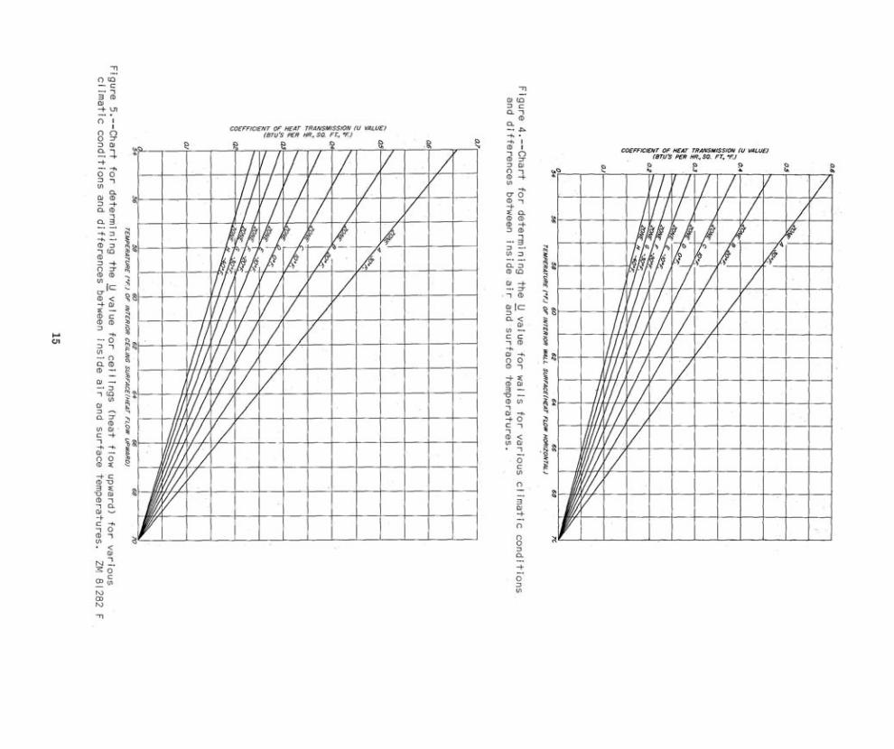
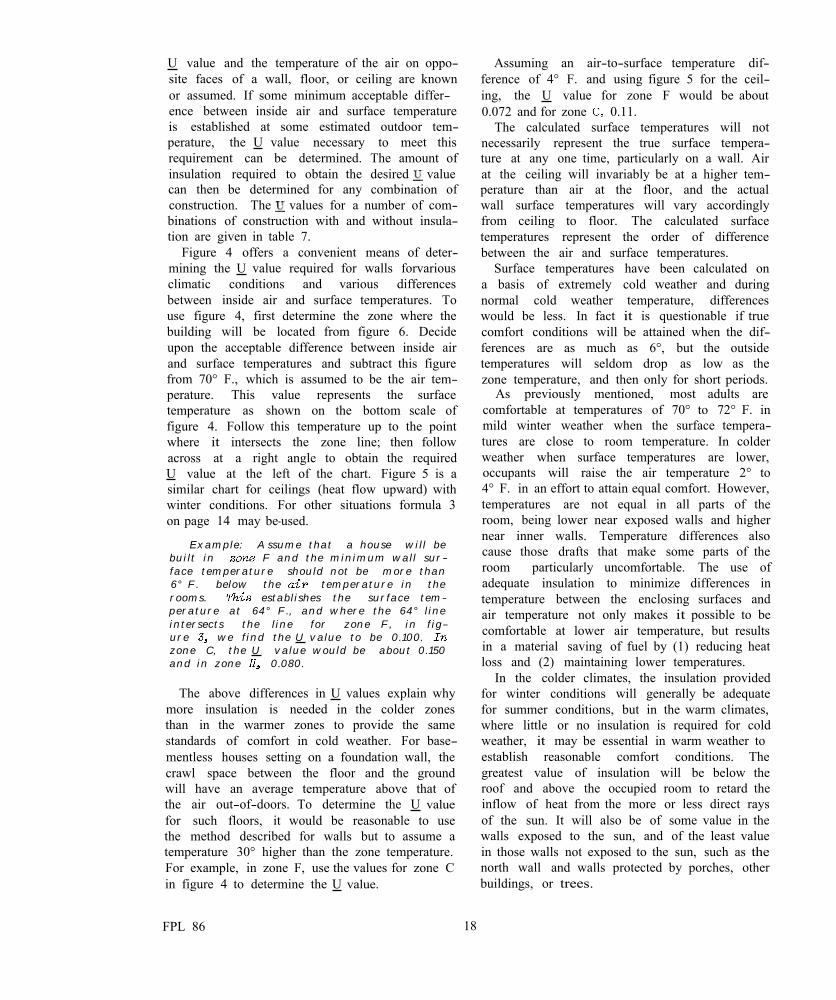
Figure 4 offers a convenient means of deter-mining the U value required for walls forvarious climatic conditions and various differences between inside air and surface temperatures. To use figure 4, first determine the zone where the building will be located from figure 6. Decide upon the acceptable difference between inside air and surface temperatures and subtract this figure from 70° F., which is assumed to be the air tem-perature. This value represents the surface temperature as shown on the bottom scale of figure 4. Follow this temperature up to the point where it intersects the zone line; then follow across at a right angle to obtain the required U value at the left of the chart. Figure 5 is a similar chart for ceilings (heat flow upward) with winter conditions. For other situations formula 3 on page 14 may be-used.
Example: Assume that a house will be built in F and the minimum wall surface temperature should not be more than 6° F. below the temperature in the rooms. establishes the surface temperature at 64° F., and where the 64° line intersects the line for zone F, in figure we find the U value to be 0.100. zone C, the U value would be about 0.150 and in zone 0.080.
The above differences in U values explain why more insulation is needed in the colder zones than in the warmer zones to provide the same standards of comfort in cold weather. For base-mentless houses setting on a foundation wall, the crawl space between the floor and the ground will have an average temperature above that of the air out-of-doors. To determine the U value for such floors, it would be reasonable to use the method described for walls but to assume a temperature 30° higher than the zone temperature. For example, in zone F, use the values for zone C in figure 4 to determine the U value.
Assuming an air-to-surface temperature dif-ference of 4° F. and using figure 5 for the ceil-ing, the U value for zone F would be about 0.072 and for zone 0.11.
The calculated surface temperatures will not necessarily represent the true surface tempera-ture at any one time, particularly on a wall. Air at the ceiling will invariably be at a higher tem-perature than air at the floor, and the actual wall surface temperatures will vary accordingly from ceiling to floor. The calculated surface temperatures represent the order of difference between the air and surface temperatures.
Surface temperatures have been calculated on a basis of extremely cold weather and during normal cold weather temperature, differences would be less. In fact it is questionable if true comfort conditions will be attained when the dif-ferences are as much as 6°, but the outside temperatures will seldom drop as low as the zone temperature, and then only for short periods.
As previously mentioned, most adults are comfortable at temperatures of 70° to 72° F. in mild winter weather when the surface tempera-tures are close to room temperature. In colder weather when surface temperatures are lower, occupants will raise the air temperature 2° to 4° F. in an effort to attain equal comfort. However, temperatures are not equal in all parts of the room, being lower near exposed walls and higher near inner walls. Temperature differences also cause those drafts that make some parts of the room particularly uncomfortable. The use of adequate insulation to minimize differences in temperature between the enclosing surfaces and air temperature not only makes it possible to be comfortable at lower air temperature, but results in a material saving of fuel by (1) reducing heat loss and (2) maintaining lower temperatures.
In the colder climates, the insulation provided for winter conditions will generally be adequate for summer conditions, but in the warm climates, where little or no insulation is required for cold weather, it may be essential in warm weather to establish reasonable comfort conditions. The greatest value of insulation will be below the roof and above the occupied room to retard the inflow of heat from the more or less direct rays of the sun. It will also be of some value in the walls exposed to the sun, and of the least value in those walls not exposed to the sun, such as the north wall and walls protected by porches, other buildings, or trees.
FPL 86 18
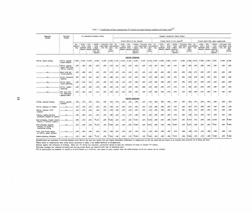
2 , 3 Table 7.--Coefficients of heat transmission (U) based on winter heating condition for frame walls

Insulation is of value in all walls in situations where it is customary to close all windows and doors and draw the shades during the hottest part of the day and to open the house to cool it off at night; here the insulation retards the inflow of heat during the period when outdoor tempera-tures are above indoor temperatures. Insulation is also of value if air-cooling systems are used. In fact the power costs required for summer cooling may be more, on a B.t.u. basis, than for winter heating.
Direct rays of the sun on a roof raise the sur-face roof temperature much above that of the air. Thus the surface temperature of the roof may raise the temperature of the closed roof and attic as much as 50" or more above outdoor tem-peratures, and the roof space then holds heat long after the sun has set. Insulation between this roof space and the ceiling below will retard, but not stop, the heat flow. Ventilation of the roof space can carry away some part of the heat that is otherwise trapped there and may lower the temperature of the roof space from 20° to 30° F. It also hastens the cooling of the roof space after the sun has set. A combination of adequate roof space ventilation and insulation will be very effective in retarding the inflow of heat through the roof and roof space into the occupied rooms below.
The amount of insulation that should be used is largely a matter of judgment, but if comfort during hot weather is the justification for insula-tion, the following maximum U values are suggested:
Side walls 0.20 Ceilings under pitched roofs 0.15 Flat roofs 0.10
Where mechanical cooling systems are used, lower values can be justified.
Using Tables of Calculated
Coefficients of Transmission
Table 7 shows the calculated coefficients of transmission, or U values, for various types of walls, ceilings, and roofs of frame construction without insulation and with various combinations of insulation. No table is shown for an attic
space between the ceiling and the roof, since the calculations for such attics are too involved for simple tabulating.
Tables 1, 2, and 7 are useful in making com-parisons between various types of construction and combinations of insulation. They show that the materials used for interior finish, sheathing, or for exterior finish have an important bearing upon the overall rate of heat transmission. They also show that, when insulation is added--as, for example, blanket-type material in the stud spaces--the rate of heat transmission decreases as the thickness of insulation increases, but not in direct relation to the increase. The first inch reduces the coefficient of heat transmission more than the second inch, and the second inch, more than the third inch.
For example, in a frame wall having a U value of 0.25 without insulation (table 7, see 3/4-inch lumber paneling), the addition of 1 inch of blanket insulation in the stud space lowers the U value to 0.11, or by 56 percent, the second inch lowers the value to 0.083, or by 67 percent, and the third inch to 0.067, or by 73 percent. If the cost of insulation were proportional to the thickness, the first inch would show the best return for the investment. However, the cost of blanket insula-tion is not proportional to its thickness, the second inch costing appreciably less than the first inch in both labor and material.
Fill types of insulation, on the other hand, are sold in bulk, and the cost of the material is proportional to the thickness used; hence the labor cost for installation would be nearly pro-portional to the thickness.
If the materials used for structural and cover-ing purposes in walls and roofs, tables 1 and 2, do not provide the desired amount of resistance to heat transmission, insulating materials must be added. In frame construction, the insulation is usually placed in the stud spaces in side walls and between joists in the attic or roof. In new construction, the insulation used in side walls is generally of a blanket type, and the same type may also be used in the roof. In level ceil-ings the fill type may be used. For existing buildings the fill type is commonly used in the stud spaces of side walls.
Where to Insulate
Insulation is used to retard the flow of heat through ceilings, walls, and floors where wide
FPL 86 20

Figure 7.--lnsulation should be installed in (1) side walls between heated rooms and outdoors, (2) in walls and floors between unheated garages and porches and heated rooms, (3) in floors of basementless houses, (4) in ceilings below unheated attics, (5) in roofs over heated rooms, (6) in side walls and below stairs leading to unheated attics.
temperature differences occur on opposite sides of those surfaces. In unheated attics, the insula-tion should he placed over the ceiling of the room below, but in heated attic spaces, the insulation should be located in the attic ceiling and down the slope of the roof to the wall plate
7). Where a dwarf wall is used between the floor and slope of the roof and the space behind the wall is not used, the insulation may be placed in the dwarf wall and across the ceiling below to the wall plate. Walls and ceilings of
ZM 81277 F
dormers and the gable ends of the attic should also be insulated if the space is heated. is desirable to insulate the walls and undersides of stairways leading to unheated attics.
In flat and pitched roofs of frame buildings, where the insulation is placed over the ceiling and below the roof, it should be so installed that there is an air space between the insulation and the roof sheathing for air circulation. In flat-roofed buildings, insulation may be placed on top of the roof deck. If this is done, there should be
21

a vapor barrier below insulation. No outside ventilation should be provided in the roof space below the insulation
All exterior walls should be insulated, includ-ing walls between heated room and unheated garages, porches, and similar spaces.
The floors over unheated garages, porches, and floors over crawl spaces or unheated base-ments should also be insulated.
Insulation of basement and cellar walls is generally less important than in the walls of rooms above grade; nevertheless, there are circumstances where i n s u l a t i o n should be considered.
Basements used only for work space, laundry, and storage may have temperatures 10° F. or more below those acceptable for living rooms. If basements are too cold for comfort or if water pipes freeze because of excessive heat loss through the basement walls, insulation may he used to reduce the heat loss, Suck conditions will be found more frequently in basements with a large part of the exterior walls above grade than where only a small part is above grade. Space in basements used for living room OF play rooms should have insulation in exterior walls.
Where water or plumbing pipes, such as those near a kitchen sink, located in exterior walls, the pipes should be as close as possible to the inside wall, and no insulation should be used between the pipes and the inside wall, All insula-tion should be on the cold side of the pipes to give maximum protection against freezing.
In hot climates. insulation can be used effec-tively to improve comfort conditions within the house. Those surfaces exposed to direct rays of the sun may attain temperatures 50° or more above temperatures in the and, of course, tend to transfer this heat toward the inside of the house. Insulation in roofs and walls retards the flow of heat, and consequently, less heat is transmitted through these exposed sur-faces to heat the atmosphere inside of house.
Where any system of cooling the air inside of the house is employed, insulation should be used in all exposed ceilings and walls in the same manner as that used for houses cold regions. In such installations, it is presumed that all windows and doors in the house will be closed during those periods when the outdoor tempera-tures are above the temperature inside. It is important that windows exposed to the sun be
shaded with awnings or that drapes curtains be drawn to reduce the flow of heat through the glass surfaces.
Ventilation of attics and roof spaces is an important adjunct to insulation. On a bright sunshiny day when outdoor temperatures are about 90° F., the temperature in a closed attic space may be 150° F., but with ventilation, the attic temperature may be reduced to about 120° or 125° F. Obviously, less heat will be trans-mitted through the ceiling to the rooms below if the attic temperature is 125° than if it is 150° F. Moreover, the closed attic remains hot for many hours after the sun has set, but the ventilated attic cools off more rapidly.
Methods of ventilation suggested for protection against condensation during cold weather apply equally well for protection against excessive roof temperatures during hot weather.
Reducing Heat Loss
in Existing Buildings
Owners of existing houses are often concerned with ways and means of reducing heat loss and improving comfort conditions in their homes. It is necessary, of course, to first determine the nature and importance of the various causes of heat loss and to consider the most practical means of reducing them. Each house must be considered as an individual problem, and each principal source of heat loss must be considered separately as it affects that house.
The heat transfer through each square foot of window surface and exposed door surface is many times that through most wall materials. In conventional construction and design, the area represented may be about percent of the total exterior wall surface, but in some houses, the area is much greater than in others. Weather strips around windows and doors will reduce air infiltration. Storm sash and storm doors will also reduce air infiltration and, in addition, reduce heat transfer by 50 percent more through the exposed surfaces. Though condensa-tion or frost may collect on single windows in mild weather, it is unlikely to form on windows protected by storm sash except at very low out-side temperature or where moisture being evap-orated in the enclosed area is excessive.
FPL 86 22
The transfer of heat and the corresponding losses of heat that occur through uninsulated ceilings and walls or between heated and unheated spaces can be reduced by insulation. Attics and roof spaces often of a type that are easy to insulate, but side walls my present a problem Table 7 may be used to estimate the extent to which it is possible to reduce the heat transfer through walls and ceilings of different types. Table 6 presents values for exterior doors with and without storm doors.
In the application of insulation to existing buildings, there are certain limitations that do not apply for new construction. In an attic where the framing are exposed, it should be possible to use any of the types that can be fitted between or over the framing members. Where the framing are enclosed, it may be necessary to use blown insulation as described �or side walls. In the side walls of a typical frame house, the members are covered on the outside with sheathing and some siding material, and on the inside with plaster or other wall finish It is impractical to introduce blanket or batt insulation to the stud space. It is possible, however, to fill the stud space with a fill-type insulation by making small openings in the out-side wall through which the insulation may be blown or poured. This is the method generally used by insulation applicators or contractors equipped for such work
On houses having wood siding, a piece of siding is removed at the top of the wall and below each window opening (fig. 8, F). Holes about 2 inches in diameter axe cut through the sheathing into each stud space. The applicator uses a plumb bob to determine the depth of the stud space and cuts additional holes where necessary below the top hole and below windows, so that he will have access to the full height of the wall. By means of a blower, insulation is forced through a hose and nozzle into each opening under a slight pressure until the stud space is completely filled. The siding is then replaced. When properly applied, there is little or no settling of the insulation.
The same general method is used for stucco, brick, and stone veneer walls. Blown insulation is also commonly used in attic and roof spaces, particularly where applied to a horizontal surface.
Some applicators follow a practice leaving the hole in the sheathing open, that such practice provides a means of escape of moisture from the wall and is a protection against conden-
sation difficulties. Tests have been made, how-ever, which show that the influence of such holes is very local in walls where condensation occurs and that they cannot be considered an effective protective measure against condensation.
Masonry walls of existing buildings, such as brick, stone, concrete, and tile, be insu-lated by the method used for frame walls. Insulating materials can be applied to interior surfaces of exterior walls where conditions are such that the and loss of space in the room are justified. One method is to apply insu-lating board 1/2 inch thick over the wall surface. It could be plastered or left exposed, depending upon the finish desired. Thicker insulating board can also be used and the resistance to heat loss increased accordingly. Another more effective method is to fur-over the old wall with 2- by 2-inch strips at 16-inch centers and apply 1-inch-blanket insulation over strips and under the insulating board, lath, or wall finish. employ-ing thicker furring strips, it is possible to use thicker blanket insulation.
Fuel Savings from Insulation
Since substantial savings of fuel can be effected by the proper use of insulation, the question naturally arises as to how much fuel might be saved for any given condition. The most satis-factory method is to approach the problem by calculation; it is reasonably accurate if the proper assumptions are used.
For an example, assume a 2-story, Colonial-type frame house about 26 by 32 feet in area, located in a suburb of Chicago. The walls have wood siding, wood sheathing, studs, and gypsum wallboard. Such a wall has a calculated U value of Assume that enough insulation is added to stud space to reduce the U value to 0.09, thereby saving 0.15 B.t.u. per square foot per hour per degree of difference in temperature on opposite sides of the wall. The area of the wall, exclusive of windows and doors, is about 1,700 square feet, and total reduction per degree of difference in temperature would be 0.15 x or 255 B.t.u. per hour °F.
The next step is to project this value of 255 B.t.u. per hour °F. into the total number of thermal units that could be saved in a normal heating year. The common unit that is used for
23

Figure 8.--Various kinds of insulation. A, structural insulating beard sheathing applied to studs. B, insulating board used as an interior walI surfacing material over the vapor barrier. C, blanket insulation In a ceiling below an attic. Blanket insulation may also be applied from below the ceiling before lath are applied. Most blanket mate-rials have tabs on the edges used in fastening the blanket in place. D, blanket insula-tion in a stud space of an outside wall, E, pouring-fill type insulation between ceil-ing joist and leveled to a uniform thickness. Note vapor barrier in part not covered. F, pneumatic method of blowing fill-type insulation into existing walls.
FPL 86 24
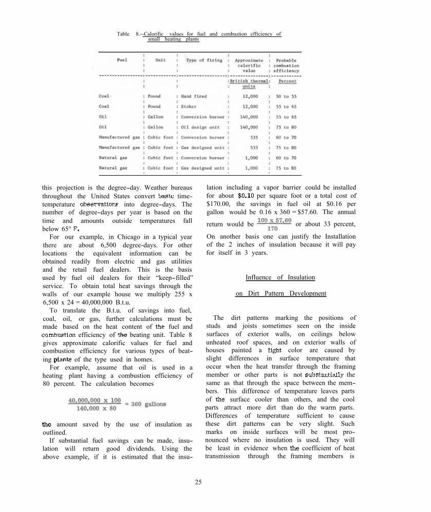
Table 8.--Calorific values for fuel and combustion efficiency of small heating plants
this projection is the degree-day. Weather bureaus throughout the United States convert time-temperature into degree-days. The number of degree-days per year is based on the time and amounts outside temperatures fall below 65°
For our example, in Chicago in a typical year there are about 6,500 degree-days. For other locations the equivalent information can be obtained readily from electric and gas utilities and the retail fuel dealers. This is the basis used by fuel oil dealers for their “keep-filled” service. To obtain total heat savings through the walls of our example house we multiply 255 x 6,500 x 24 = 40,000,000 B.t.u.
To translate the B.t.u. of savings into fuel, coal, oil, or gas, further calculations must be made based on the heat content of fuel and
efficiency of beating unit. Table 8 gives approximate calorific values fer fuel and combustion efficiency for various types of beat-ing of the type used in homes.
For example, assume that oil is used in a heating plant having a combustion efficiency of 80 percent. The calculation becomes
amount saved by the use of insulation as outlined.
If substantial fuel savings can be made, insu-lation will return good dividends. Using the above example, if it is estimated that the insu-
lation including a vapor barrier could be installed for about per square foot or a total cost of $170.00, the savings in fuel oil at $0.16 per gallon would be 0.16 x 360 = $57.60. The annual
return would be or about 33 percent,
On another basis one can justify the Installation of the 2 inches of insulation because it will pay for itself in 3 years.
Influence of Insulation
on Dirt Pattern Development
The dirt patterns marking the positions of studs and joists sometimes seen on the inside surfaces of exterior walls, on ceilings below unheated roof spaces, and on exterior walls of houses painted a color are caused by slight differences in surface temperature that occur when the heat transfer through the framing member or other parts is not the same as that through the space between the mem-bers. This difference of temperature leaves parts of surface cooler than others, and the cool parts attract more dirt than do the warm parts. Differences of temperature sufficient to cause these dirt patterns can be very slight. Such marks on inside surfaces will be most pro-nounced where no insulation is used. They will be least in evidence when coefficient of heat transmission through the framing members is
25

the same as that through the space between members.
Very pronounced dirt patterns may appear on some surfaces in 1 to 2 years after these sur-faces have been decorated. This may be taken as evidence that the heat transfer through these surfaces is high, affecting comfort, fuel economy, and maintenance. It may take 10 years or more for the same degree of pattern to develop on surfaces where insulation has been used in construction unit.
A comparison of temperatures may be deter-mined by computation. Assume a conventional frame wall having a U value of through the stud space and 0.140 through the stud, an outside temperature of 0° F., and an inside temperature of 70° Using formulas given in the section on calculating “Inside Surface Temperatures,” we find that the surface temperature over the stud space would be 70 - 11.7 or 58.3° F., and over the stud 70 - 6.7 or 63.3° F., a difference of 5.0°
If wall at the stud space has a U value of 0.107, equivalent to the use of I-inch-blanket insulation, the calculated surface temperature would be - 5.0 or 65.0° F. For a stud space with a U value of 0.075, equivalent to the use of a 2-inch blanket, the calculated surface temper-ature would be - 3.6 or 66.4° F. The temper-ature differences between the surface over the stud and the air between studs are 1.7 and 3.1, respectively, much less than for uninsulated wall. Moreover, the greater the difference between room and surface temperature, the greater the air movement that carries the dirt particles to the surface,
Where drywall construction is used, involving such materials as insulating board. plywood, gypsum board, and similar materials, the wall finish is often attached to the studs with nails through the face of the covering material. The nail is a better conductor of heat than the wall material and in consequence, a dirt pattern my outline each nailhead. The type of material used will in some cases establish the size and shape of the nail. Where the requirements of the mate-rial permit, short nails having small heads should be used. The nails should as deep as possible, to minimize the dirt pattern. Some types of material are attached with concealed clips, some are held in place with glue or mastic. By using these types of fastenings, the dirt pattern characteristic where are used will he avoided.
WOOD AND WOOD-BASE INSULATION
Those materials that have high resistance to heat transmission called thermal insulators or more commonly, insulation. Since wood has better thermal properties than most other build-ing materials, such as brick, stone, concrete, or plaster, it might be called insulation. However, when the wood is made into fibrous products of low-to-moderate density. it becomes far superior to solid wood in thermal properties. The term “insulation” is, therefore, generally applied to materials, including wood-base materials, that have thermal properties superior to that of solid wood. Even among the materials called insulation, there are variations in thermal. properties, as some types of insulation are more resistive than others. Commercial insulation is manufactured in a variety of forms and types, each having certain advantages for specific uses and no one type being best for all applications. This report is concerned only with those obtained from wood.
Fox purposes of description, the various kinds of materials (fig. 8) used commonly for insula-tion my be grouped within the following general classes: A, rigid insulation, (1) structural, (2) non-structural; B, flexible insulation; C, fill insula-tion; and D, miscellaneous types.
Rigid Insulation
Structural.--Structural insulating board is a term generally applied to a type of product made by seducing wood, cane, or other lignocellulosic fibers to a pulp, and then assembling the fibrous material into large lightweight or low-density boards that combine strength with heat- and sound-insulating properties. Such material may also be used for decorative purposes. The fin-ished board as generally made is 6 to 12 feet long, 4 feet wide, and to 1 inch thick. Greater thicknesses are also furnished, usually lam-inating the material of standard thickness to obtain the thickness desired. Insulating board products can be used for numerous pur-poses and consequently are furnished in a variety of sizes and finishes. The most common products are building board, sheathing, roof insulation board, roof deck, factory-finished interior board,
FPL 86 26

insulated siding base, insulating form board, and shingle backer.
Building board.--Building board is a general purpose insulating board supplied in widths of 4 feet, in lengths from 6 to 12 feet, and in thick-nesses of 1/2 1 inch.
Regular-density sheathing.--As the name implies, sheathing is intended for use as a cover-ing on walls. It is furnished in widths of 2 and 4 feet, lengths of 8 to 12 feet, and thicknesses of
and 25/32 inches. It may be obtained with a natural finish or with surface coatings, generally of asphaltic material. Material in this class generally has a density of about pounds per cubic foot.
Inter ior board.--Factory-finished interior board is regularly furnished with a factory-applied fire-retardant paint finish in the follow-ing types: (1) Board, (2) plain tile, (3) acoustical tile, (4) plank, and (5) lay-in panel.
Board is usually 1/2 inch thick and 4 by 8 feet in area and is applied as full-sized panels or is cut up and used in other manu-facture. Some material 3/8 inch thick is mar-keted as “thin-board” for remanufacture.
Plain and acoustic tile are made in small squares or rectangular patterns generally with tongued and grooved interlocking edges, and are used for interior finish, particularly in ceilings. They are available in a variety of sizes from 12 by 12 to 16 by 32 inches and in thicknesses of 1/2, 3/4, 1 inch.
Plank is another type of interior finish used in conjunction with the board. It is used as sidewall material particularly in moderniz-ing or finishing extra rooms. It is made in widths ranging from 8 to 16 inches and lengths from 8 to 12 feet, with the usual thickness being 1/2 inch. Plank is factory finished in a variety of colors and textures.
Lay-in panel is a specially fabricated 1/2-inch-thick panel, nominally 2 by 2 or 2 by 4 feet in size, and used for suspended ceiling systems wherein the panels are supported an a grid of metal or other framing. Lay-in panel material is finished in the same way as tile. Insulating roof deck.--Insulating roof deck for
roof decking is made up in panels 2 by 8 foot and in nominal thicknesses of 1-1/2, 2, and 3 inches. The lower face is of 1/2-inch, factory-finish interior board and the remaining layers are of sheathing-quality board. A vapor barrier is incorporated between the interior and sheathing
quality boards when condensation control is desired .
Insulating roof deck is manufactured to pro-vide the structural strength and rigidity for the roof construction as well as the desired thermal insulation. Each manufacturer furnishes the insu-lating roof deck in slightly more than nominal thickness, so that roofs constructed with it will have “C” factor values of 0.24, 0.18, and 0.12 British thermal. units per hour square foot difference in temperature for heat flow up (winter heating) for the respective thicknesses of 1-1/2, 2, and 3 inches.
For most areas, design requirements are met if the 1-1/2-inch decking is used
where spans do not exceed 24 inches. the 2-inch decking where do not exceed 32 inches, and the 3-inch decking where spans do not exceed 48 inches.
Insulated aiding base.--Some sheathing grade board is manufactured into insulating siding. The board is given further impregnation of asphalt and then coated on one side with asphalt and granules or plastic to make a build-ing siding that has the appearance wood, stone, or brick Material simulating wood is applied as lapped siding. Insulating siding that simulates stone or brick is applied in panels with matched joints.
Shingle backer.--Shingle backer is a product, usually 5/16 inch thick, used for backing of coursed shingle siding. It adds some insulation, a shadow line that enhances appearance. and, when properly used, eliminates the need for nail-ing strips over insulation board sheathing.
Roof insulating board.--This insulating board product is made expressly for above-deck ther-mal insulation, where the board in blocks about 2 feet wide, 4 feet long and 1/2 to 3 inches thick is laid in pitch on flat or nearly flat roofs, and a builtup roofing membrane is applied over it,
Cork blocks.--Cork are made bond-ing small pieces of cork together in blocks or slabs ranging from 12 by 36 inches to 36 by 36 inches and from 1 to 6 inches in thickness. This product is used widely for cold storage insulation and for insulating the flat roofs of industrial and commercial buildings.
Wood-wool cement panels.--This wood-base material is usually used as decking material in commercial buildings. It is manufactured in panels 2 by 8 feet in size and up to about 4 inches
27

thick It is made by bonding wood excelsior or similar elements with an inorganic cement like portland. Besides providing adequate strength to support roof loadings and moderate thermal insu-lation, these materials have good flame-spread ratings. This panel material is used also in non-load-bearing partitions and in small tile form for ceiling finish where the principal function is acoustical absorption.
Special high-density insulating board sheathing.--Most sheathing-grade i n s u l a t i n g board is manufactured in a density range of 16 to 18 pounds per cubic foot (regular-density), Two additional qualities of sheathing-grade insu-lating board of higher density are also being used--intermediate-density sheathing from 19 to 25 pounds per cubic foot and nail-base sheathing from 22 to 27 pounds per cubic foot. They are less effective thermal insulators than the regular-density products. Their increased density, how-ever, gives them improved racking resistance when used in walls. They are regularly manu-factured in 1/2-inch thickness, 4 feet wide, and 8, 9, or 10 feet long, Nail-base sheathing in addition provides an adequate base for direct attachment by nailing of wood or cement asbestos shingles as siding.
Flexible Insulation
Flexible insulation is manufactured in two classes or (1) blanket or quilt, and (2) batt. Blanket insulation is generally furnished in rolls or strips of convenient length and in various widths suited to standard stud and joist spacing. The thicknesses range from about 1/2 inch to 3-1/2 inches. This insulation may be made of loosely felted mats of wood fiber or chemically treated wood-fiber products. The fibers used are generally chemically treated to make them resistive to fire, decay, and vermin. Quilts may also be made of multiple layers of paper, plain ox creped, stitched together.
Most blanket insulating materials are supplied with a covering sheet of paper on one or both sides, and this covering material has tabs on the sides of the blanket used for fastening it in place. The covering sheet on one side be of a type intended to serve as a vapor barrier. In some cases the covering sheet may be sur-faced with aluminum foil or other materials to
provide reflective insulation. Blanket insulations are also manufactured without the paper cover-ing, the fibers having sufficient strength to hold the material in the intended form and shape.
Batt insulation is generally thicker than blanket, up to inches thick, is made in widths to fit between framing and lengths of 4 or 8 feet.
Fill Insulation
Loose, fill-type insulation is generally com-posed of materials used in bulk form, usually supplied in bags or bales and intended to be poured or blown into place or packed by hand. It is used to fill wall spaces or to build up any desired thickness on horizontal surfaces. Wood products most commonly used are wood fiber, granulated cork, shredded redwood bark, ground or macerated newsprint, and to a limited extent sawdust and shavings, which are not as efficient insulators as the more finely divided material.
Reflective Insulation
Most materials reflect radiant heat, cer-tain ones have this property a high degree. For reflective insulation, high and low emissivity are required. as provided by aluminum foil, sheet metal with polished surface coating, and paper products coated with reflective materials. Reflective insulation is available in a variety of forms, usually as foil or coatings mounted on paper backing and on the back of gypsum lath and wallboard. is used in combination with blanket insulation as the sur-face cover of one or both faces. Reflective insu-lation, to be effective, must be installed with the reflective surfaces facing or exposed to an air space 3/4 inch or more in depth. Reflective materials in contact with other sur-faces lose their reflective properties. To be effective, air spaces in conjunction with reflective insulation should not be so great that convective air currents reduce the effect of the reflective properties.
Emissivity, as used here, applies to the emis-sion ox radiation of radiant heat from a surface on the warm side of an ais space, and reflectivity applies to the of radiant heat from a surface on the cold side of an air space.
FPL 28
Miscellaneous Insulating Materials
There are, of course, insulation materials that do not fit into the classification described, such as (1) confetti-like material mixed with adhesive and sprayed on surface to be insulated, and (2) multiple layers of corrugated paper.
COLD WEATHER AND OTHER CONDENSATION A S
INFLUENCED BY INSULATION
Condensation Within Walls and Roofs
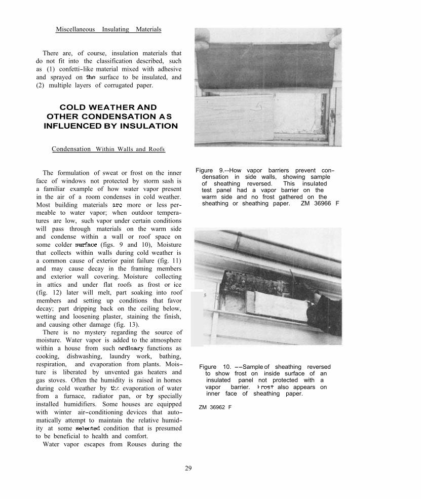
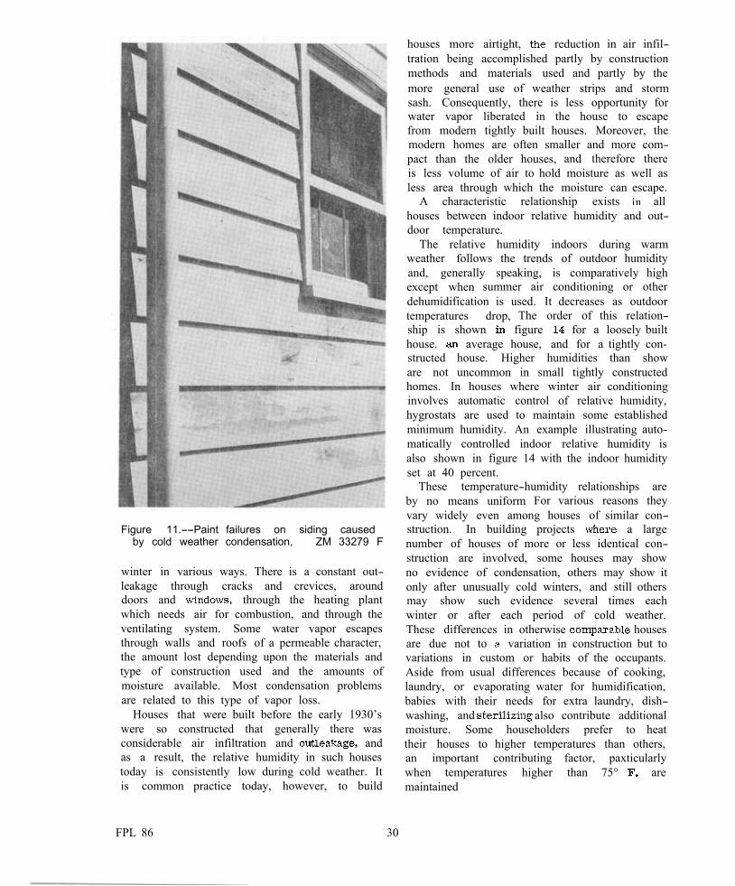
The formulation of sweat or frost on the inner face of windows not protected by storm sash is a familiar example of how water vapor present in the air of a room condenses in cold weather. Most building materials more or less per-meable to water vapor; when outdoor tempera-tures are low, such vapor under certain conditions will pass through materials on the warm side and condense within a wall or roof space on some colder (figs. 9 and 10), Moisture that collects within walls during cold weather is a common cause of exterior paint failure (fig. 11) and may cause decay in the framing members and exterior wall covering. Moisture collecting in attics and under flat roofs as frost or ice (fig. 12) later will melt, part soaking into roof members and setting up conditions that favor decay; part dripping back on the ceiling below, wetting and loosening plaster, staining the finish, and causing other damage (fig. 13).
There is no mystery regarding the source of moisture. Water vapor is added to the atmosphere within a house from such functions as cooking, dishwashing, laundry work, bathing, respiration, and evaporation from plants. Mois-ture is liberated by unvented gas heaters and gas stoves. Often the humidity is raised in homes during cold weather by evaporation of water from a furnace, radiator pan, or specially installed humidifiers. Some houses are equipped with winter air-conditioning devices that auto-matically attempt to maintain the relative humid-ity at some condition that is presumed to be beneficial to health and comfort.
Water vapor escapes from Rouses during the
Figure 9.--How vapor barriers prevent con-densation in side walls, showing sample of sheathing reversed. This insuIated test panel had a vapor barrier on the warm side and no frost gathered on the sheathing or sheathing paper. ZM 36966 F
Figure 10. --Sample of sheathing reversed to show frost on inside surface of an insulated panel not protected with a vapor barrier. also appears on inner face of sheathing paper.
ZM 36962 F
29
houses more airtight, reduction in air infil-tration being accomplished partly by construction methods and materials used and partly by the more general use of weather strips and storm sash. Consequently, there is less opportunity for water vapor liberated in the house to escape from modern tightly built houses. Moreover, the modern homes are often smaller and more com-pact than the older houses, and therefore there is less volume of air to hold moisture as well as less area through which the moisture can escape.
A characteristic relationship exists all houses between indoor relative humidity and out-door temperature.
The relative humidity indoors during warm weather follows the trends of outdoor humidity and, generally speaking, except when summer air dehumidification is used. temperatures drop, The ship is shown figure house. average house, structed house. Higher
is comparatively high conditioning or other
It decreases as outdoor order of this relation-
for a loosely built and for a tightly con-
humidities than show
Figure 11.--Paint failures on siding caused by cold weather condensation, ZM 33279 F
winter in various ways. There is a constant out-leakage through cracks and crevices, around doors and through the heating plant which needs air for combustion, and through the ventilating system. Some water vapor escapes through walls and roofs of a permeable character, the amount lost depending upon the materials and type of construction used and the amounts of moisture available. Most condensation problems are related to this type of vapor loss.
Houses that were built before the early 1930’s were so constructed that generally there was considerable air infiltration and and as a result, the relative humidity in such houses today is consistently low during cold weather. It is common practice today, however, to build
are not uncommon in small tightly constructed homes. In houses where winter air conditioning involves automatic control of relative humidity, hygrostats are used to maintain some established minimum humidity. An example illustrating auto-matically controlled indoor relative humidity is also shown in figure 14 with the indoor humidity set at 40 percent.
These temperature-humidity relationships are by no means uniform For various reasons they vary widely even among houses of similar con-struction. In building projects a large number of houses of more or less identical con-struction are involved, some houses may show no evidence of condensation, others may show it only after unusually cold winters, and still others may show such evidence several times each winter or after each period of cold weather. These differences in otherwise houses are due not to variation in construction but to variations in custom or habits of the occupants. Aside from usual differences because of cooking, laundry, or evaporating water for humidification, babies with their needs for extra laundry, dish-washing, and also contribute additional moisture. Some householders prefer to heat their houses to higher temperatures than others, an important contributing factor, paxticularly when temperatures higher than 75° are maintained
FPL 86 30
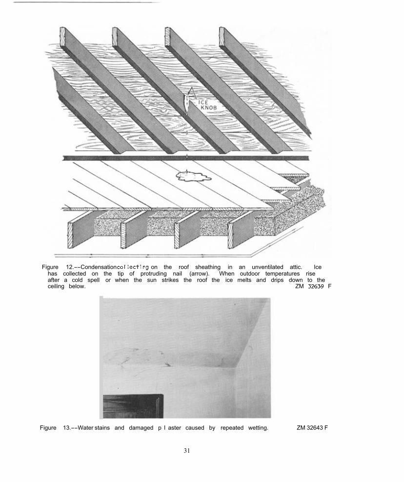
Figure 12.--Condensation on the roof sheathing in an unventilated attic. Ice has collected on the tip of protruding nail (arrow). When outdoor temperatures rise after a cold spell or when the sun strikes the roof the ice melts and drips down to the ceiling below. ZM F
Figure 13.--Water stains and damaged p I aster caused by repeated wetting. ZM 32643 F
31
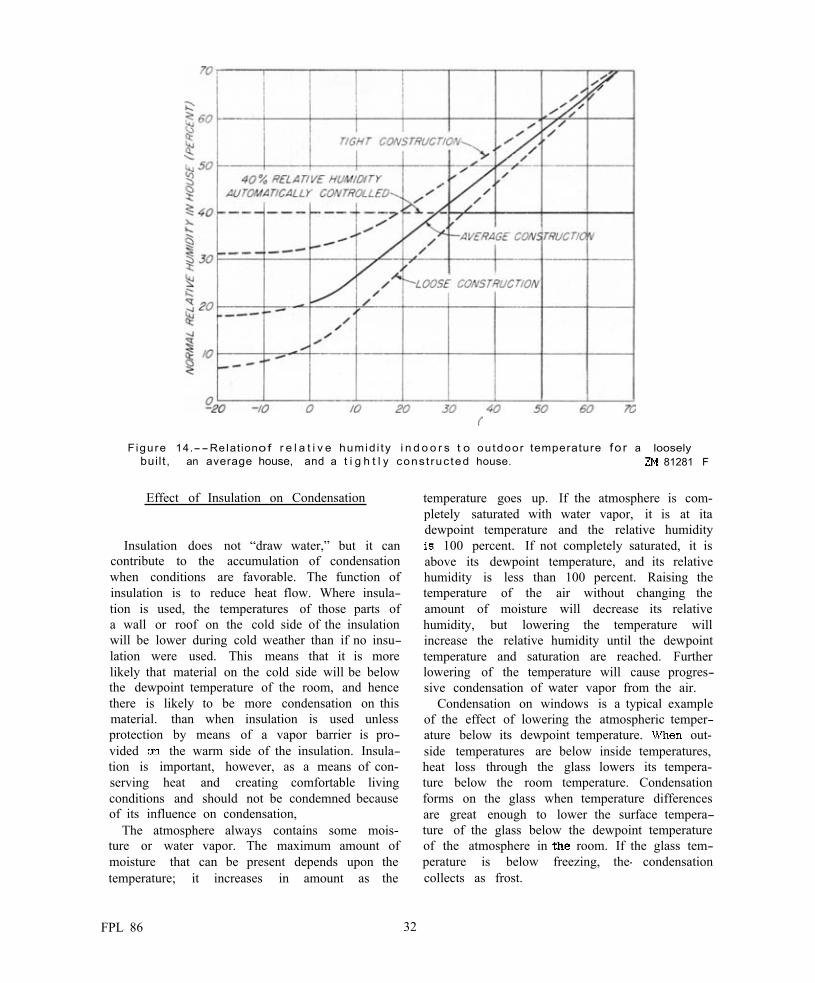
Figure 14.--ReIationof r e l a t i v e humid i ty i n d o o r s t o outdoor temperature fo r a loosely buil t , an average house, and a t i g h t l y const ruc ted house. 81281 F
Effect of Insulation on Condensation
Insulation does not “draw water,” but it can contribute to the accumulation of condensation when conditions are favorable. The function of insulation is to reduce heat flow. Where insula-tion is used, the temperatures of those parts of a wall or roof on the cold side of the insulation will be lower during cold weather than if no insu-lation were used. This means that it is more likely that material on the cold side will be below the dewpoint temperature of the room, and hence there is likely to be more condensation on this material. than when insulation is used unless protection by means of a vapor barrier is pro-vided the warm side of the insulation. Insula-tion is important, however, as a means of con-serving heat and creating comfortable living conditions and should not be condemned because of its influence on condensation,
The atmosphere always contains some mois-ture or water vapor. The maximum amount of moisture that can be present depends upon the temperature; it increases in amount as the
temperature goes up. If the atmosphere is com-pletely saturated with water vapor, it is at ita dewpoint temperature and the relative humidity
100 percent. If not completely saturated, it is above its dewpoint temperature, and its relative humidity is less than 100 percent. Raising the temperature of the air without changing the amount of moisture will decrease its relative humidity, but lowering the temperature will increase the relative humidity until the dewpoint temperature and saturation are reached. Further lowering of the temperature will cause progres-sive condensation of water vapor from the air.
Condensation on windows is a typical example of the effect of lowering the atmospheric temper-ature below its dewpoint temperature. out-side temperatures are below inside temperatures, heat loss through the glass lowers its tempera-ture below the room temperature. Condensation forms on the glass when temperature differences are great enough to lower the surface tempera-ture of the glass below the dewpoint temperature of the atmosphere in room. If the glass tem-perature is below freezing, the- condensation collects as frost.
FPL 86 32
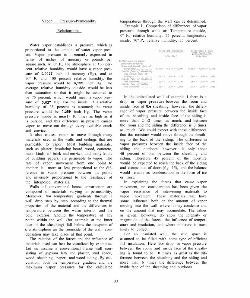
Vapor Pressure-Permeability
Relationships
Water vapor establishes a pressure, which is proportional to the amount of water vapor pres-ent. Vapor pressure is expressed in terms of inches of mercury or pounds per square inch. At 0° F., the atmosphere at per-cent relative humidity would have a vapor pres-sure of inch of mercury (Hg), and at 70° and 100 percent relative humidity, the vapor pressure would be inch Hg. The average relative humidity outside would be less than saturation so that it might be assumed to be 75 percent, which would mean a vapor pres-sure of Hg. For the inside, if a relative humidity 35 percent is assumed; the vapor pressure would be inch Hg. The vapor pressure inside is 10 times as high as it is outside, and this difference in pressure causes vapor to move out through every available crack and crevice.
It also causes vapor to move through many materials used in the walls and ceilings that are permeable to vapor. Most building materials, such as plaster, insulating board, wood, concrete, most kinds of brick and and many kinds of building papers, are permeable to vapor. The rate of vapor movement from one point to another is more or less proportional to the dif-ference in vapor pressure between the points and inversely proportional to the resistance of the interposed materials.
Walls of conventional house construction are composed of materials varying in permeability, Moreover, temperature gradients through a wall drop step by step according to the thermal properties of the material and the differences in temperature between the warm interior and the cold exterior. Should the temperature at any point within the wall (for example at the inner face of the sheathing) fall below the dewpoint of
atmosphere an the roomside of the wall, con-densation may take place at that point.
The relation of the forces and the influence of materials used can best be visualized by examples. Let us assume a conventional frame wall con-sisting of gypsum lath and plaster, stud space, wood sheathing, paper, and wood siding. By cal-culation, both the temperature gradient and the maximum vapor pressures for the calculated
temperatures through the wall can be determined. Example 1. Comparison of differences of vapor
pressure through walls at: Temperature outside, 0° F.; relative humidity, 75 percent; temperature inside, 70° relative humidity, 35 percent.
In the uninsulated wall of example 1 there is a drop in vapor between the room and inside face of sheathing; however, the differ-ence of vapor pressure between the inside face of the sheathing and inside face of the siding is more than 2-1/2 times as much, and between the room and the siding the difference is 3 times as much. We could expect with these differences that moisture would move through the sheath-ing to the back of the siding. The difference in vapor pressures between the inside face of the siding and outdoors, however, is only about
percent of that between the sheathing and siding. Therefore 45 percent of the moisture would be expected to reach the back of the siding and escape out-of-doors (fig. 15), and the balance would remain as condensation in the form of ice or frost.
In explaining the forces that cause vapor movement, no consideration has been given the vapor resistance of intervening materials to vapor movement. These materials will have some influence both on the amount of vapor moving into the wall where it may condense and on the amount that may accumulate. The values as given. however, do show the intensity or magnitude of the forces, the influence of temper-ature and insulation, and where moisture is most likely to collect.
For an insulated wall, the stud space is assumed to be filled with some type of efficient fill insulation. Here drop in vapor pressure between the room and inside face of the sheath-ing is found to be times as great as the dif-ference between the sheathing and the siding and more than 6 times the difference between the inside face of the sheathing and outdoors.
33

Figure 15.--Stains on a painted wall caused by condensation collecting behind siding in cold weather as ice, and melting when the weather moderated. The water drains out through laps in the siding carrying water-soluble extractives that cause the stain. This building, located in Wisconsin, had no vapor barrier. ZM 77407 F
a basis of the differences in pressure, it can be estimated that for each 6 parts of water vapor moving into the wall, only 1 part would move out and 5 parts would remain as condensa-tion, collecting on the inner face of the sheatking.
Example 2. Conditions: Temperature outside, 0° F.; relative humidity, 75 percent; temperature inside, 80° F.; relative humidity, 35 percent.
In example 2, the conditions are similar to example 1 except that, owing to the increased room temperature, the differences of vapor pressure are materially increased. In the uninsu-lated wall, the difference between room and siding is 3.7 times the difference between siding and outdoors. In the insulated wall, the difference between room and sheathing is 8.3 times the difference between sheathing and outdoors.
Materials used in wall construction vary widely in resistance to vapor transmission The com-parative resistance of such materials is an important factor influencing vapor movement. Over a of years, various investigators have tested the resistance of different materials to moisture movement by diffusion, conducting
FPL 86 34
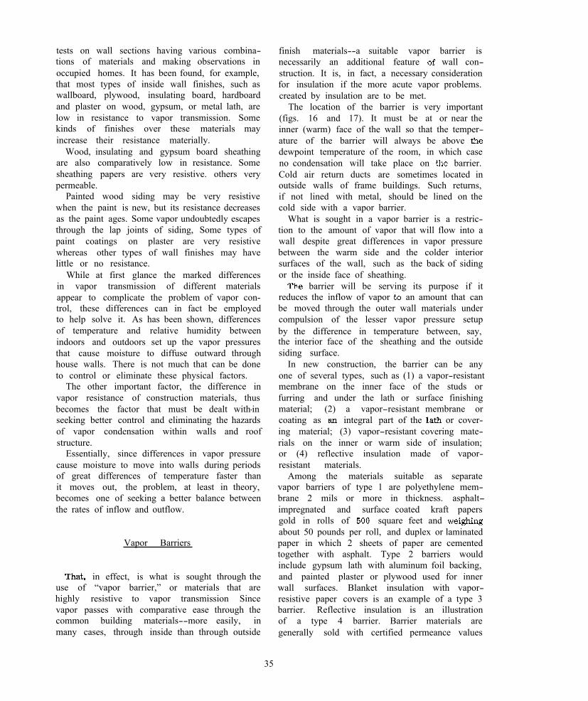
tests on wall sections having various combina-tions of materials and making observations in occupied homes. It has been found, for example, that most types of inside wall finishes, such as wallboard, plywood, insulating board, hardboard and plaster on wood, gypsum, or metal lath, are low in resistance to vapor transmission. Some kinds of finishes over these materials may increase their resistance materially.
Wood, insulating and gypsum board sheathing are also comparatively low in resistance. Some sheathing papers are very resistive. others very permeable.
Painted wood siding may be very resistive when the paint is new, but its resistance decreases as the paint ages. Some vapor undoubtedly escapes through the lap joints of siding, Some types of paint coatings on plaster are very resistive whereas other types of wall finishes may have little or no resistance.
While at first glance the marked differences in vapor transmission of different materials appear to complicate the problem of vapor con-trol, these differences can in fact be employed to help solve it. As has been shown, differences of temperature and relative humidity between indoors and outdoors set up the vapor pressures that cause moisture to diffuse outward through house walls. There is not much that can be done to control or eliminate these physical factors.
The other important factor, the difference in vapor resistance of construction materials, thus becomes the factor that must be dealt with-in seeking better control and eliminating the hazards of vapor condensation within walls and roof structure.
Essentially, since differences in vapor pressure cause moisture to move into walls during periods of great differences of temperature faster than it moves out, the problem, at least in theory, becomes one of seeking a better balance between the rates of inflow and outflow.
Vapor Barriers
in effect, is what is sought through the use of “vapor barrier,” or materials that are highly resistive to vapor transmission Since vapor passes with comparative ease through the common building materials--more easily, in many cases, through inside than through outside
finish materials--a suitable vapor barrier is necessarily an additional feature wall con-struction. It is, in fact, a necessary consideration for insulation if the more acute vapor problems. created by insulation are to be met.
The location of the barrier is very important (figs. 16 and 17). It must be at or near the inner (warm) face of the wall so that the temper-ature of the barrier will always be above dewpoint temperature of the room, in which case no condensation will take place on barrier. Cold air return ducts are sometimes located in outside walls of frame buildings. Such returns, if not lined with metal, should be lined on the cold side with a vapor barrier.
What is sought in a vapor barrier is a restric-tion to the amount of vapor that will flow into a wall despite great differences in vapor pressure between the warm side and the colder interior surfaces of the wall, such as the back of siding or the inside face of sheathing.
barrier will be serving its purpose if it reduces the inflow of vapor an amount that can be moved through the outer wall materials under compulsion of the lesser vapor pressure setup by the difference in temperature between, say, the interior face of the sheathing and the outside siding surface.
In new construction, the barrier can be any one of several types, such as (1) a vapor-resistant membrane on the inner face of the studs or furring and under the lath or surface finishing material; (2) a vapor-resistant membrane or coating as integral part of the or cover-ing material; (3) vapor-resistant covering mate-rials on the inner or warm side of insulation; or (4) reflective insulation made of vapor-resistant materials.
Among the materials suitable as separate vapor barriers of type 1 are polyethylene mem-brane 2 mils or more in thickness. asphalt-impregnated and surface coated kraft papers gold in rolls of square feet and about 50 pounds per roll, and duplex or laminated paper in which 2 sheets of paper are cemented together with asphalt. Type 2 barriers would include gypsum lath with aluminum foil backing, and painted plaster or plywood used for inner wall surfaces. Blanket insulation with vapor-resistive paper covers is an example of a type 3 barrier. Reflective insulation is an illustration of a type 4 barrier. Barrier materials are generally sold with certified permeance values
35

Figure 16.--Methods of insulating ceilings. The sketches show the use of vapor barriers for condensation control and the arrangement of several types of thermal insulation.
ZM 81238 F
on their label. Permeance values are generally expressed in
“perm” which are grains of water vapor pass-ing through a square foot of material per hour per inch of mercury difference in vapor pres-sure. A material with a low “perm” value is a barrier, while one with a high “perm” value is a “breather.” There is not complete agreement as to what “perm” value is the maximum per-missible for a vapor barrier. For general con-
struction purposes materials with a permeance of less than one perm are usually considered to be barriers. By way of comparison a 2-mil polyethylene film has a permeance of 0.16 perm
In new construction, vapor barrier permeance values are now commonly specified by building code authorities, depending on local conditions and other features of construction. For example if the vapor resistance of the outside of a wall construction is high (low permeance), it
FPL 86 36

Figure 17.--Vapor barriers instal led on the inner face of the studding. interior finish placed over the barriers and nailed to the studding holds the paper or plastic film tight at the laps and no special seal is required. ZM 34059 F
will be necessary to use a better barrier on the inside wall than if the outside wall is a “breather.”
Vapor barriers may be either incorporated with or installed separately from other materials of the wall structure. Barriers of type 1 are separately installed; those of types 2 and 3 are integrated with other wall materials the manufacturer; and those of type 4 are in effect dual-purpose materials, since the same material provides both the insulation and the vapor barrier.
Type 1 barrier materials should be to the inner face of the stud, in back of the lath or other wall finishing material. Type 2 is auto-matically located in the proper position Type 3 should have the vapor-resistant surface faced towards the inside of house with the insulation toward the outside. Type 4 should have the reflective face toward the inside of the house.
Paint coatings on plaster may be effective as vapor barriers if materials are properly chosen and applied. Of these, coats of aluminum
primer followed by decorative coats of flat paint, or one coat of pigmented primer and sealer paint (not glue size) followed by decora-tive finish coats, offer the best resistance and may be satisfactory in older houses. However this is below the standard desired for new con-struction. For dry-wall construction where ply-wood, insdating board, or other wall materials are used in place of plaster, paint coatings may be applied to the back or to the face. Asphalt coatings on the back of plywood, for example, make an excellent barrier. Two coats, or enough to a bright shiny finish, are required. It also important that outflow of vapor from a wall should not be impeded by materials of relatively high resistance on the cold side of the vapor barrier. Sheathing paper should be of a type that is waterproof but not vapor proof, such as tarred felt.
Ventilation in Attics and Roofs
Condensation occurs in attic spaces and under flat roofs in the same manner as in walls. It collects as frost or ice on the roof boards, on projecting nails, and frequently between the roof sheathing and exterior coverage. bright, sun-shiny days, even at low temperatures, the frost melts and water drops to the ceiling below, where it causes stain and other damage. Stain and decay of roof members is quite common.
It has become almost standard practice for to install louvered openings in the gable
ends of houses to provide ventilation through attic spaces (fig. 18). When these openings func-tion properly, there is generally little evidence of condensation. Some, however. are too small, some do not face prevailing winds, and for numerous other reasons many fail to function as intended. They cannot be installed in all types of roofs, such as hip roofs and some flat roofs. Even where ventilation is provided by the builder, the householder may close the openings to con-serve heat or for some other reason, and the intended protection is thus lost.
The moisture problem in attic spaces and on the underside of flat roofs is usually aggravated by the use of highly impermeable roofing, such as asphalt shingles or roofing.
Vapor barriers should be installed in the ceil-ings under attics and flat roofs in the same
37
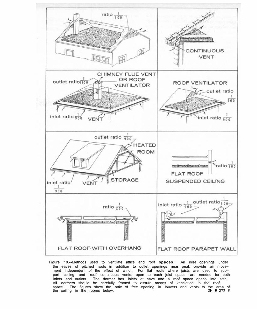
Figure 18.--Methods used to ventilate attics and roof spaces. Air inlet openings under the eaves of pitched roofs in addition to outlet openings near peak provide air move-ment independent of the effect of wind. For flat roofs where joists are used to sup-port ceiling and roof, continuous vents, open to each joist space, are needed for both inlets and outlets. The dormer has inlets at eave and a roof space opens into attic. All dormers should be carefully framed to assure means of ventilation in the roof space. The figures show the ratio of free opening in louvers and vents to the area of the ceiling in the rooms below. F

manner as for walls. It is to be expected that some vapor will work into the roof space through the barrier or through places not fully protected by a barrier, such as doors and around pipes ducts. The amount is small and, if uniformly dis-tributed over the roof, should be unimportant. However, the condensation tends to collect in the coldest parts, and the concentration of moisture may be enough to cause trouble. A combination of vapor barriers and ventilation is obviously the safest procedure.
Figure 18 shows recommended sizes of venti-lators for various types of roofs expressed as a percentage of the ventilator area per square foot of projected ceiling area below the roof space. For roof spaces having no occupied rooms, the ceiling area may be assumed as area within the exterior wall line. For attic space with occupied rooms, determine the pro-jected ceiling area below the attic and add enough additional area to take care of the knee walls and sloping ceilings.
For gable-roof houses with open attics where there is little or no overhang of the roof at the eaves. louvered openings in the gabled ends having a ratio of 1 square foot of net opening to 300 square feet of ceiling area are For attics with overhanging eaves or with occupied room, provide openings under the eaves and louvered openings in the gables having the ratio of opening to ceiling areas as shown in figure 18.
roofs, where louvered openings cannot be used, can be vented by various means. Globe ventilators at or near the ridge with inlet open-ings under the cornice around the perimeter of the house are efficient. Special flues may be provided in chimneys with suitable openings into the attic or roof space. hip roofs may be built with louvered openings at the peak Minimum areas for such are shown in figure 18. Minimum areas do nut provide for screen Where 16-mesh screen used, the minimum area of the screen should be at least double that of the area specified. In most this can be accomplished by providing a frame of proper size inside of the opening to hold the screen.
Openings below overhanging eaves or in the soffit or cornices should preferably be continuous. In most cases, it may be practical to provide an opening back of a bed mold. Many manufacturers now provide prefabricated soffit material with screened openings to provide this needed
Ventilation in flat roofs should be provided in accordance with the roof framing. Where one solid member is used for both ceiling and roof joist, there is no intercommunication between joist spaces, and openings should be provided for each space, Flat roofs that overhang wall below can often be provided with openings under the overhang. A continuous opening three-fourths inch wide is generally sufficient for a house of average size.
The Forest Products and others have been studying reports of trouble with con-densation in houses from various parts of the United States for many years. In normal or mild winters most of these reports are from areas north of the Ohio River, but after a severe winter, such as occurs every 4 or 5 the reports are more numerous and include many from areas farther south. On a basis of these studies, it been well established that con-densation problems may be expected in houses in those parts of the country where the average January temperature is 35° F. or lower.
At the time it is built, every new house of the 35° isotherm (fig. 19) should be provided with some positive form of protection against condensation In the light of our present knowledge, vapor barriers on warm side of the wall and under the roof seem to the most assured form of protection and are inex-pensive. For existing houses, suitable paint coat-ings over the inside surfaces of exterior walls and ceilings will generally prove satisfactory. Priming coats of pigmented primer and sealer or aluminum paint, followed by one or two decorative coats of oil base flat paint, offer good resistance. Tests have shown that, with suitable integral vapor barriers or suitable paint coat-ings, adequate protection is obtained in houses with or without insulation maintained at relative humidities as high as 40 percent in the coldest weather.
Crawl Space Condensation Control
Changing styles in house design and equipment in recent years has meant that many houses are being built without basements. Two common methods of construction are used for basement-less houses. For one, a concrete slab is laid over the ground. For other, wood joists are
39
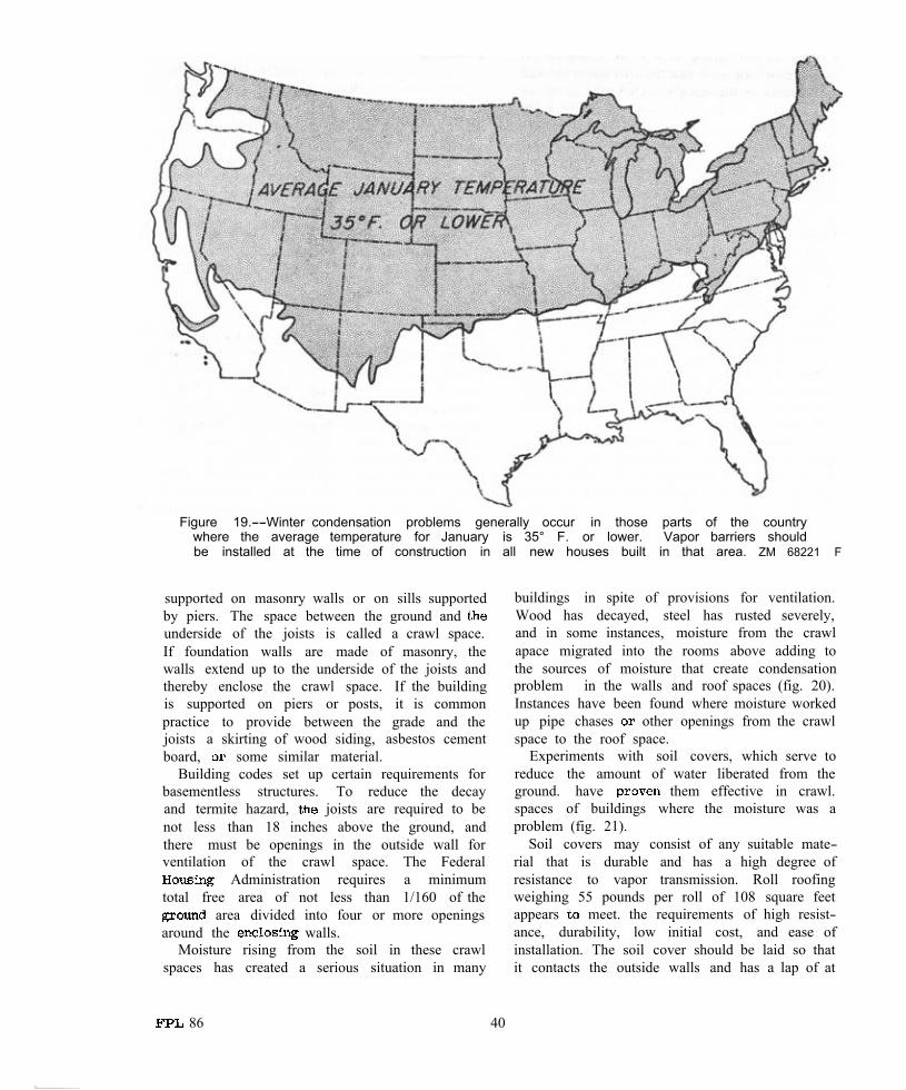
Figure 19.--Winter condensation problems generally occur in those parts of the country where the average temperature for January is 35° F. or lower. Vapor barriers should be installed at the time of construction in all new houses built in that area. ZM 68221 F
supported on masonry walls or on sills supported by piers. The space between the ground and underside of the joists is called a crawl space. If foundation walls are made of masonry, the walls extend up to the underside of the joists and thereby enclose the crawl space. If the building is supported on piers or posts, it is common practice to provide between the grade and the joists a skirting of wood siding, asbestos cement board, some similar material.
Building codes set up certain requirements for basementless structures. To reduce the decay and termite hazard, joists are required to be not less than 18 inches above the ground, and there must be openings in the outside wall for ventilation of the crawl space. The Federal
Administration requires a minimum total free area of not less than 1/160 of the
area divided into four or more openings around the walls.
Moisture rising from the soil in these crawl spaces has created a serious situation in many
buildings in spite of provisions for ventilation. Wood has decayed, steel has rusted severely, and in some instances, moisture from the crawl apace migrated into the rooms above adding to the sources of moisture that create condensation problem in the walls and roof spaces (fig. 20). Instances have been found where moisture worked up pipe chases other openings from the crawl space to the roof space.
Experiments with soil covers, which serve to reduce the amount of water liberated from the ground. have them effective in crawl. spaces of buildings where the moisture was a problem (fig. 21).
Soil covers may consist of any suitable mate-rial that is durable and has a high degree of resistance to vapor transmission. Roll roofing weighing 55 pounds per roll of 108 square feet appears meet. the requirements of high resist-ance, durability, low initial cost, and ease of installation. The soil cover should be laid so that it contacts the outside walls and has a lap of at
86 40
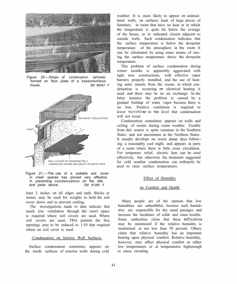
Figure 20.--Drops of condensation (arrows) formed on floor joists of a basementless house. ZM 80047 F
Figure 21.--The use of a suitable soiI cover in crawl spaces has proved very effective in preventing condensation on the sills and joists above. ZM 81280 F
least 2 inches on all edges and ends. Bricks or stones may be used for weights to hold the soil cover down and to prevent curling,
The investigations made to date indicate that much less ventilation through the crawl space is required where soil covers are used. Where soil covers are used, FHA permits the free openings area to be reduced to 1/10 that required where no soil cover is used.
Condensation on Interior Wall Surfaces
Surface condensation sometimes appears on the inside surfaces of exterior walls during cold
weather. It is most likely to appear on uninsul-lated walls, on surfaces hack of large pieces of furniture, in room that have no heat or in which the temperature is quite far below the average of the house, or in unheated closets adjacent to outside walls. Such condensation indicates that the surface temperature is below the dewpoint temperature of the atmosphere in the room It can be eliminated by using some means of rais-ing the surface temperature above the dewpoint temperature.
This problem of surface condensation during winter months is apparently aggravated with tight new constructions, with effective vapor barriers properly installed, and the use of heat-ing units remote from the rooms in which con-densation is occurring electrical heating is used and there may be no air exchange. In the latter instance the problem is caused by a gradual buildup of water vapor because there is no loss. Positive ventilation is required to lower to level that condensation will not occur.
Condensation sometimes appears on walls and ceiling of rooms during warm weather. Trouble from this source is quite common in the Southern States and not uncommon in the Northern States. It usually develops on warm damp days follow-ing a reasonably cool night, and appears in parts of a room where there is little cross circulation. For temporary relief, electric fans can be used effectively, but otherwise the treatment suggested for cold weather condensation can ordinarily be used to raise surface temperatures.
Effect of Humidity
on Comfort and Health
Many people are of the opinion that low humidities are unhealthful, because such humid-ities are responsible for dry nasal passages and increase the incidence of colds and sinus trouble. Some authorities claim that these may be minimized if the relative humidity is maintained at not less than 50 percent. Others claim that relative humidity has an important bearing upon physical comfort. Relative humidity, however, may affect physical comfort at either low temperatures or at temperatures highenough to cause sweating.
41
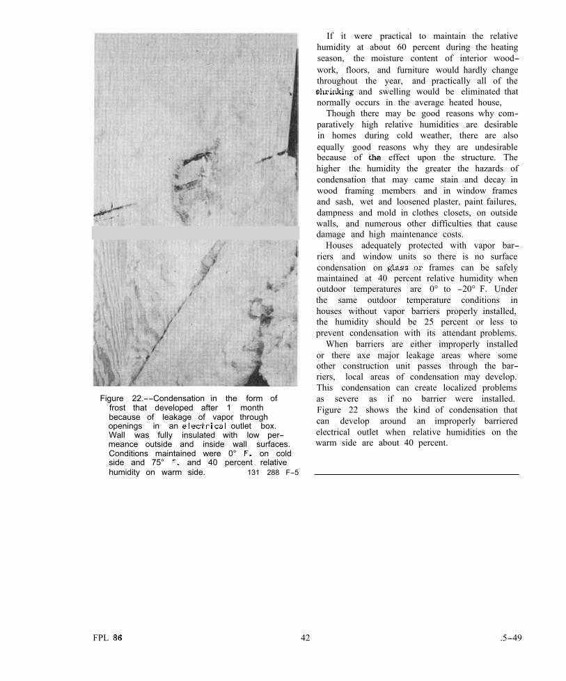
Figure 22.--Condensation in the form of frost that developed after 1 month because of leakage of vapor throughopenings in an outlet box. Wall was fully insulated with low per-meance outside and inside wall surfaces. Conditions maintained were 0° on cold side and 75° and 40 percent relative humidity on warm side. 131 288 F-5
If it were practical to maintain the relative humidity at about 60 percent during the heating season, the moisture content of interior wood-work, floors, and furniture would hardly change throughout the year, and practically all of the
and swelling would be eliminated that normally occurs in the average heated house,
Though there may be good reasons why com-paratively high relative humidities are desirable in homes during cold weather, there are also equally good reasons why they are undesirable because of effect upon the structure. The higher the humidity the greater the hazards of condensation that may came stain and decay in wood framing members and in window frames and sash, wet and loosened plaster, paint failures, dampness and mold in clothes closets, on outside walls, and numerous other difficulties that cause damage and high maintenance costs.
Houses adequately protected with vapor bar-riers and window units so there is no surface condensation on frames can be safely maintained at 40 percent relative humidity when outdoor temperatures are 0° to -20° F. Under the same outdoor temperature conditions in houses without vapor barriers properly installed, the humidity should be 25 percent or less to prevent condensation with its attendant problems.
When barriers are either improperly installed or there axe major leakage areas where some other construction unit passes through the bar-riers, local areas of condensation may develop. This condensation can create localized problems as severe as if no barrier were installed. Figure 22 shows the kind of condensation that can develop around an improperly barriered electrical outlet when relative humidities on the warm side are about 40 percent.
FPL 42 .5-49

Selected Bibliography
1. American Society of Heating, Refrigerating and Air-conditioning Engineers (ASHRAE).
Handbook of fundamentals, heating, refrigerating, ventilating and air conditioning. (544 pp.).
2. Anderson, L.O., and Heyer, O.C. 19 5 5. Wood-frame house construction. U. S.
Dep. Agr., Forest Serv., Agr. Handb. 73.
3. Building Research Advisory Board. 1952. Condensation control in buildings. Nat.
Res. Counc. 118 pp., illus. 4. Close, P.D.
1966. Sound control and thermal insulation. Rheinhold Publishing Corp., N.Y.
5. Dill, R.S., Robinson, W.C. and Robinson, H.E. 1945. Measurement of heat losses slab
floors. National Bur. Stand., Building Materials and Structures Report BMS 103. 21 pp., illus.
6. Diller, J.D. 1953. Soil cover reduces decay hazard in
basementless houses. U.S. Bur. Plant Ind., Soils, and Agr. Eng., Div. Forest Path., Spec. Rel. 38.
7. M.E. 1949. Condensation control in dwelling con
struction. U.S. Housing and Home Finance Agency. 74 pp., illus.
8. Fahey, D.J., M.E., and Seidl, R.J. 1953. Thermal conductivity of paper honey
comb cores and sound absorption of sandwich panels. Forest Prod. Lab. Rep. 1952.
9. Insulation Board Institute. Fundamentals of building insulation.
(Revised annually.) Insulation Board Institute, Chicago, Ill. 42 pp.
10. Lewis, Wayne C. 1967. Thermal conductivity of wood-base
fiber and particle panel materials. U.S. Forest Serv. Res. Paper FPL 77, Forest Prod. Lab., Madison, Wis.
11. MacLean, J.D. 1941. Thermal conductivity of wood. Amer.
Soc. Heating and Ventilating Eng. J., Sec. Heating, Piping, and Air Conditioning.
12. Rogers, T.S. 1964. Thermal design of buildings. John Wiley
and Sons, New York. 13. Teesdale, L.V.
1955. Remedial measures for building construction. Forest Prod. Lab. Rep. R1710 (Rev.), 27 pp., illus.
U.S. Department of Agriculture
Forest Service