thermal mini printer
TRANSCRIPT
CP103 Thermal Mini Printer
User Instructions
AWT 35-501163 Issue AB

CP103 printer_u_en_501163.book
Brecknell is a trademark of the Illinois Tool Works group of companies whose ultimate parent company is Illinois Tool Works Inc (“Illinois Tool Works”). Copyright © 2013 Illinois Tool Works. All rights reserved.
No part of this publication may be reproduced by making a facsimile copy, by the making of a copy in three dimensions of a two-dimensional work and the making of a copy in two dimensions of a three-dimensional work, stored in any medium by electronic means, or transmitted in any form or by any means, including electronic, mechanical, broadcasting, recording or otherwise without the prior written consent of the copyright owner, under license, or as permitted by law.
This publication was correct at the time of going to print, however Avery Weigh-Tronix reserves the right to alter without notice the specification, design, price or conditions of supply of any product or service at any time.

CP103 Thermal Printer User Instructions 1
Table of ContentsChapter 1 General Information and Warnings ........................................................................................ 2
About this Manual .............................................................................................................. 2Special Messages ....................................................................................................... 2
Description ......................................................................................................................... 2Package and Accessories .................................................................................................. 3Warnings ............................................................................................................................ 3Prepare the Printer for Use ................................................................................................ 3Signal Light Status ............................................................................................................. 4
Power Light ................................................................................................................. 4Feed Light ................................................................................................................... 4
Specifications ..................................................................................................................... 4Paper Roll Specifications ................................................................................................... 5
Chapter 2 Communication ........................................................................................................................ 6RS-232 Serial Interface ...................................................................................................... 6CP103 Printer PS/2 Connector .......................................................................................... 6Serial Cable Definition ....................................................................................................... 7
Chapter 3 Printer Self Test and Cleaning ................................................................................................ 8Cleaning the Print Head ..................................................................................................... 8
Steps for Cleaning Print Head ..................................................................................... 8
Chapter 4 Programming ............................................................................................................................ 9Communicate with the Printer .......................................................................................... 10
Select Printer Type .................................................................................................... 10Select COM Port ....................................................................................................... 10Check Printer Baud Rate ........................................................................................... 11Select Baud Rate ...................................................................................................... 11
Make Changes to Printer Configuration ........................................................................... 12Change Printer Baud Rate ........................................................................................ 12Set the Printer Data Bits ............................................................................................ 13Set the Printer Stop Bit .............................................................................................. 13Set the Printer Parity ................................................................................................. 14Restore Default Baud Rate ....................................................................................... 14Time and Date ........................................................................................................... 15Company Information ................................................................................................ 16Underline Printing ...................................................................................................... 17Inverse Font .............................................................................................................. 18Line Feed .................................................................................................................. 18Character Dot Choice ................................................................................................ 19Font Choice ............................................................................................................... 19Time and Date Display Mode .................................................................................... 20Print Height and Width .............................................................................................. 20Upside Down Printing ................................................................................................ 21Printer Escape Command Code Definitions .............................................................. 21Logo Download ......................................................................................................... 22
2 CP103 Thermal Printer User Instructions
1 General Information and Warnings
1.1 About this Manual
This manual is divided into chapters by the chapter number and the large text at the top of a page. Subsections are labeled as shown by the 1 and 1.1 headings shown above. The names of the chapter and the next subsection level appear at the top of alternating pages of the manual to remind you of where you are in the manual. The manual name and page numbers appear at the bottom of the pages.
1.1.1 Special Messages
Examples of special messages you will see in this manual are defined below. The signal words have specific meanings to alert you to additional information or the relative level of hazard.
1.2 Description
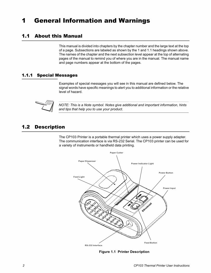
The CP103 Printer is a portable thermal printer which uses a power supply adapter. The communication interface is via RS-232 Serial. The CP103 printer can be used for a variety of instruments or handheld data printing.
Figure 1.1 Printer Description
NOTE: This is a Note symbol. Notes give additional and important information, hints and tips that help you to use your product.
RS-232 InterfaceFeed Button
Power Input
Power Button
Power Indicator Light
Paper Cutter
Feed Light
Paper Dispenser

CP103 Thermal Printer User Instructions 3
1.3 Package and Accessories
l Portable Thermal Printer
l RS-232 Serial Data Cable
l Thermal Paper Roll
l Driver disc (for RS-232/USB)
1.4 Warnings
l Read all operating instructions carefully before use.
l Avoid lengthy exposure to extreme heat or cold. Your printer works best when operated at normal room temperature.
1.5 Prepare the Printer for Use
1. Install a roll of thermal paper in paper dispenser by lifting the dispenser cover and placing the paper in with the thermal side facing outward. Refer to Figure 1.1 for paper dispenser location.
1a. To test which side is thermal, run a fingernail across the paper. A mark should show on the paper. If no mark appears, try the other side of the paper.
2. With about 1/2 inch of paper sticking out, close the paper dispenser cover.
3. Connect RS-232 cable by plugging the PS/2 end of the cable to the printer. Refer to Figure 1.1 for PS/2 connector location.
4. Connect AC power adapter to the printer by plugging the adapter connector into the printer power supply plug. Refer to Figure 1.1 for power input location.
5. When ready, plug the other end of the AC adapter into a wall socket.
6. Plug the RS-232 serial cable in the host device.
7. Press the [POWER] button to turn on the printer.

4 CP103 Thermal Printer User Instructions
1.6 Signal Light Status
1.6.1 Power Light
1.6.2 Feed Light
1.7 Specifications
Power Light Light Color Printer Status Specification
Steady red light Red In the process of recharging battery
Red light blinks one time slowly every one second Red Battery power is low, recharge battery
Steady green light Green Battery voltage is good
Blinks between red and green light Red/Green Battery failure
Blinks 3 times between red and green light Red/Green Printing is finished or printer is in power on mode
No light None No power is detected
Feed light Light Color Printer status specification
Steady red light Red Feed paper or receiving data
Red light blinks quickly (2 times/sec) Red No paper
Red light blinks 3 times and then stops Red Printer parameter setting is finished and ok
Steady green light Green Printer status is ok but not connected bluetooth
Always alternating blink between red and green light Red/Green Printer dead, the buffer is full or temperature of printhead is too high
Item Specification
Dimension (W×D×H) 104×75×48mm
Weight 145g (without battery and paper roll)
Print Width 58mm
Print Speed 90mm/s (MAX)
Memory 10K byte buffer and 8M byte flash
Interface RS-232 baud rate 4800 - 115200bps
Resolution 8 dot/mm (203dpi)
Language Support Figure, English characters, bit-image, bar code, curve
Character Size ANK: 12*24(dot), 1.5*3.0 (W*L, mm);Chinese Character: 24*24 (dot), 3.0*3.0 (W*L, mm)
Print Commands ESC/POS compatible command set
Other Features Paper auto-detection, power detection, thermal protection, with machine charging, automatic sleeping mode
Working Conditions Temperature: 0° - 50°, Humidity 20% - 85%
Storage Conditions Temperature: -20° - 70°, Humidity 5% - 95%

CP103 Thermal Printer User Instructions 5
1.8 Paper Roll Specifications
Item Specification
Roll Width: 58mm
Roll Diameter: ≤ 43mm
Paper Thickness 0.06 - 0.08mm
Paper Type Thermal

6 CP103 Thermal Printer User Instructions
2 CommunicationThe CP103 Mini Thermal Printer uses a RS-232 serial interface connection with the host communication. If a serial port is unavailable on the host device, it is possible to use a serial / USB converter.
2.1 RS-232 Serial Interface
RS-232 is developed according to the EIA standard asynchronous transmission serial interface. The specifications are as following:
l Data transmission: serial interface
l Synchronization: asynchronous
l Signal Level: RS-232 level, logic 1:-5.4v, logic 0: +5.4v
l Hardware Flow Control: optional
l Baud rate: 1200 bps to 115200 bps (NOTE: At 1200 baud, continous printing mode of data sending from Host is not supported)
l Data word length: 8 bits
l Stop bit: 1bit
l Parity: None
The printer self-testing page will show the current baud rate. The default baud rate is 115200bps. Refer to Chapter 3 for details on the Printer Self Test.
2.2 CP103 Printer PS/2 Connector
The following drawing illustrates the PS2 socket pinout located on the CP103 printer. This connection is used for RS-232 communication with an indicator or computer and requires the PS2 to RS-232 interface cable (serial cable).
Pin Description
1 TXD - data output
2 no connection
3 GND
4 no connection (12V DC- IN is optional)
5 RXD - data input
6 no connection (12V DC- IN is optional)

CP103 Thermal Printer User Instructions 7
2.3 Serial Cable Definition
Wire Colors PS2 Connector Pinoutmale
Pin Description DB9 Pinoutfemale
white 1 TXD 2
blue 2 Null 8
black 3 GND 5
yellow 4 12 V Input 7
red 5 RXD 3
green 6 12 V Input 6
5 1
9 6
4 3 2
8 7

8 CP103 Thermal Printer User Instructions
3 Printer Self Test and CleaningWith the printer off, press and hold the [POWER] button until the printer begins to print a self-testing page and then release the [POWER] button.
The page gives specific information regarding version of firmware, interface type, print speed, default baud rate, etc.
3.1 Cleaning the Print Head
When the printer displays the following symptoms the print head should be cleaned:
l The printer does not print clearly and the thermal paper is good
l The page-test printing is not crisp and clear
l Paper feed is noisy
3.1.1 Steps for Cleaning Print Head
1. Turn off the power to the printer and open the paper dispenser cover. Remove the thermal paper roll.
1a. If the printer was just printing then wait for the print head to cool down.
2. With a soft cotton cloth dipped in rubbing alcohol (make sure there is no dripping), wipe the thermal printer head gently and remove any dust or debris.
3. Wait for the rubbing alcohol to evaporate completely and then place the thermal paper roll back in the printer. Close the paper dispenser cover and print a test page.
CP103 Thermal Printer User Instructions 9
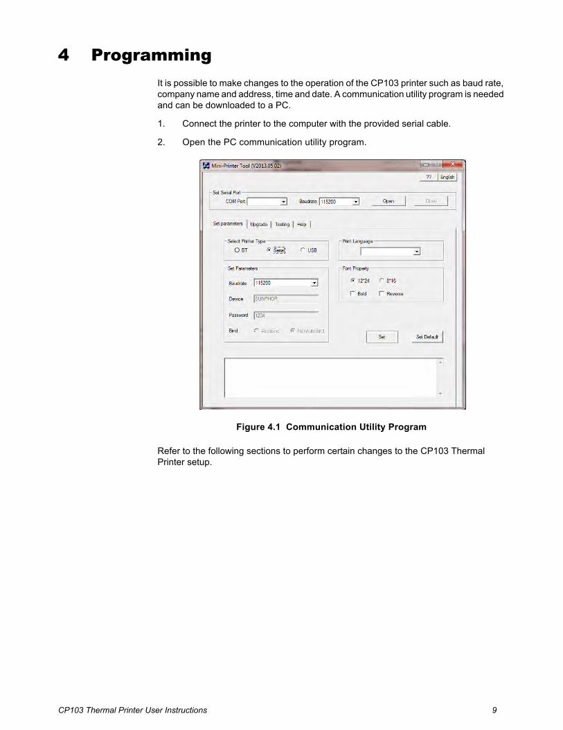
4 ProgrammingIt is possible to make changes to the operation of the CP103 printer such as baud rate, company name and address, time and date. A communication utility program is needed and can be downloaded to a PC.
1. Connect the printer to the computer with the provided serial cable.
2. Open the PC communication utility program.
Figure 4.1 Communication Utility Program
Refer to the following sections to perform certain changes to the CP103 Thermal Printer setup.

10 CP103 Thermal Printer User Instructions
4.1 Communicate with the Printer
4.1.1 Select Printer Type
From the Set parameters tab under Select Printer Type, choose “Serial”.
4.1.2 Select COM Port
Select the PC communication port the printer is connected to.
Under Set Serial Port choose the correct COM port from the drop down choices.
CP103 Thermal Printer User Instructions 11
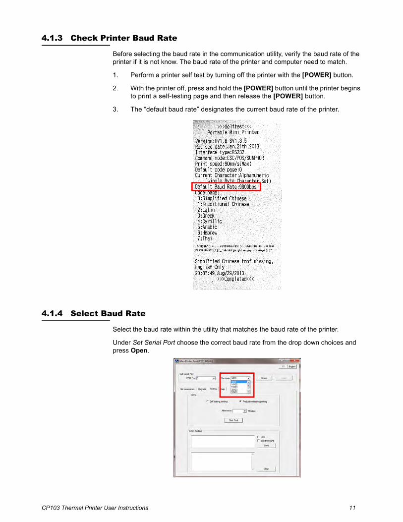
4.1.3 Check Printer Baud Rate
Before selecting the baud rate in the communication utility, verify the baud rate of the printer if it is not know. The baud rate of the printer and computer need to match.
1. Perform a printer self test by turning off the printer with the [POWER] button.
2. With the printer off, press and hold the [POWER] button until the printer begins to print a self-testing page and then release the [POWER] button.
3. The “default baud rate” designates the current baud rate of the printer.
4.1.4 Select Baud Rate
Select the baud rate within the utility that matches the baud rate of the printer.
Under Set Serial Port choose the correct baud rate from the drop down choices and press Open.
12 CP103 Thermal Printer User Instructions
4.2 Make Changes to Printer Configuration
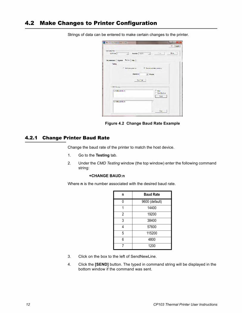
Strings of data can be entered to make certain changes to the printer.
Figure 4.2 Change Baud Rate Example
4.2.1 Change Printer Baud Rate
Change the baud rate of the printer to match the host device.
1. Go to the Testing tab.
2. Under the CMD Testing window (the top window) enter the following command string:
+CHANGE BAUD:n
Where n is the number associated with the desired baud rate.
3. Click on the box to the left of SendNewLine.
4. Click the [SEND] button. The typed in command string will be displayed in the bottom window if the command was sent.
n Baud Rate
0 9600 (default)
1 14400
2 19200
3 38400
4 57600
5 115200
6 4800
7 1200
CP103 Thermal Printer User Instructions 13
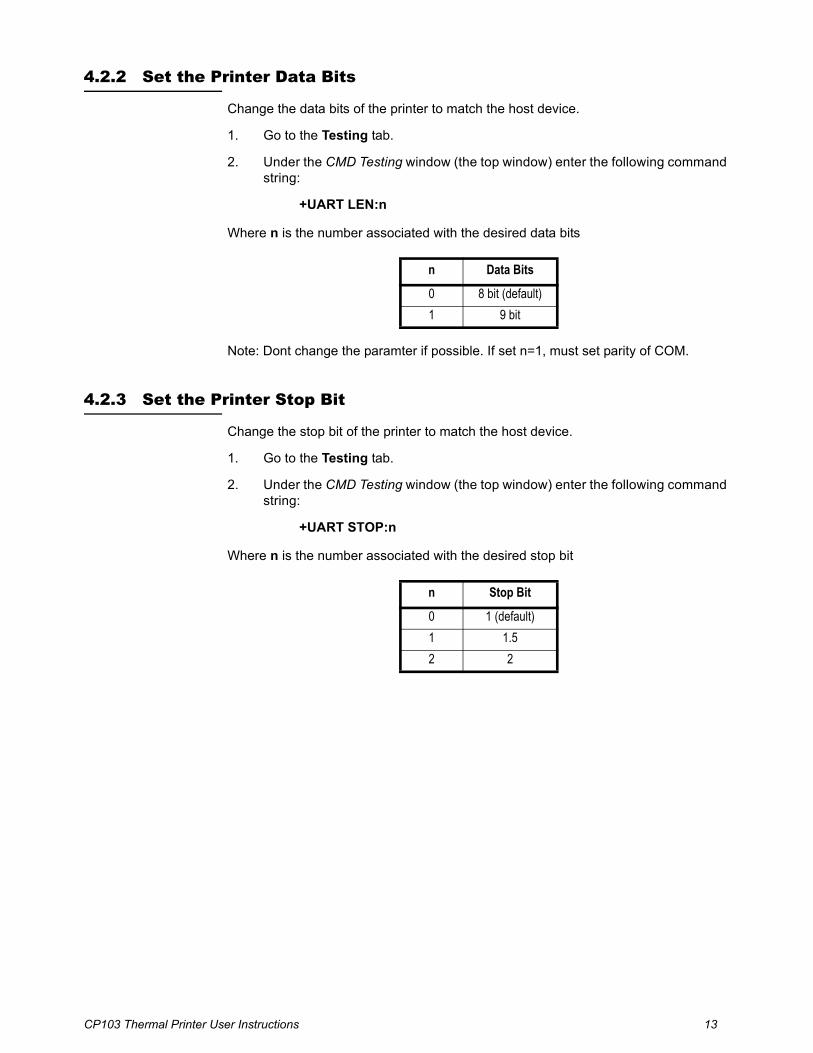
4.2.2 Set the Printer Data Bits
Change the data bits of the printer to match the host device.
1. Go to the Testing tab.
2. Under the CMD Testing window (the top window) enter the following command string:
+UART LEN:n
Where n is the number associated with the desired data bits
Note: Dont change the paramter if possible. If set n=1, must set parity of COM.
4.2.3 Set the Printer Stop Bit
Change the stop bit of the printer to match the host device.
1. Go to the Testing tab.
2. Under the CMD Testing window (the top window) enter the following command string:
+UART STOP:n
Where n is the number associated with the desired stop bit
n Data Bits
0 8 bit (default)
1 9 bit
n Stop Bit
0 1 (default)
1 1.5
2 2
14 CP103 Thermal Printer User Instructions
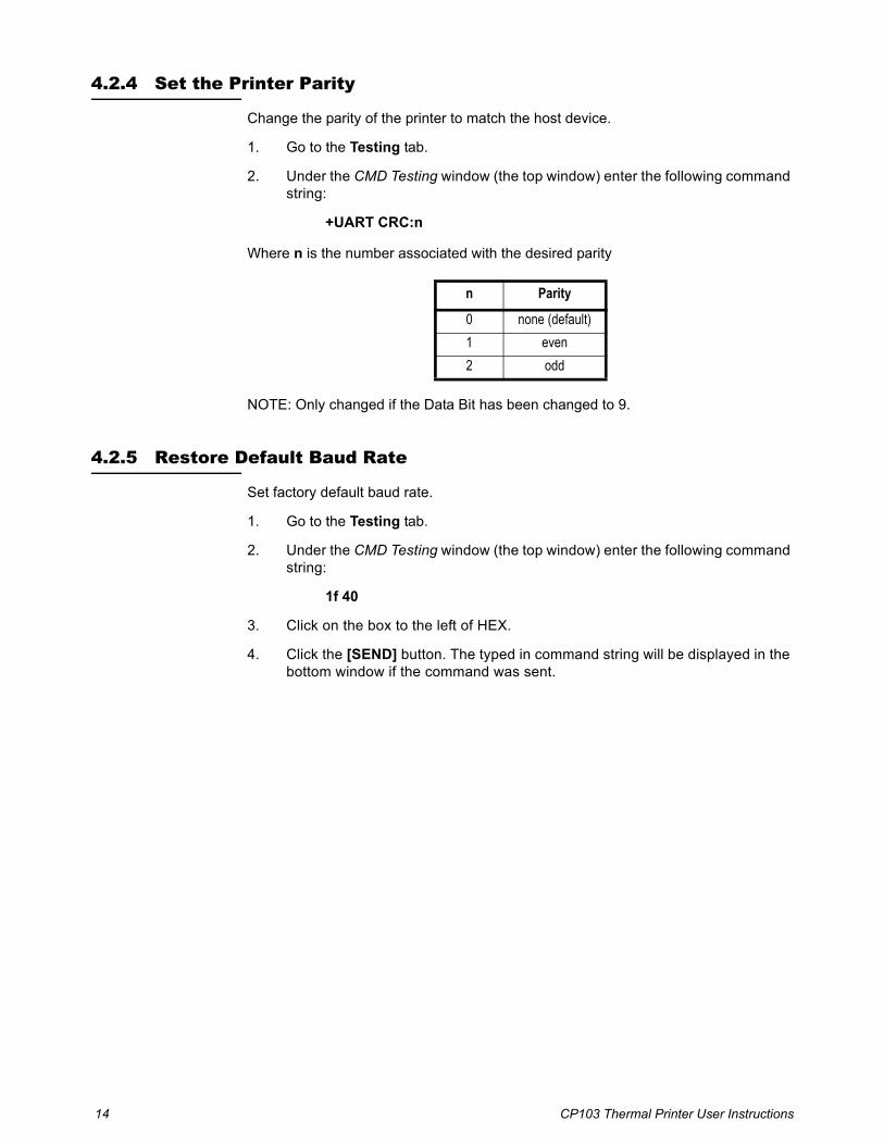
4.2.4 Set the Printer Parity
Change the parity of the printer to match the host device.
1. Go to the Testing tab.
2. Under the CMD Testing window (the top window) enter the following command string:
+UART CRC:n
Where n is the number associated with the desired parity
NOTE: Only changed if the Data Bit has been changed to 9.
4.2.5 Restore Default Baud Rate
Set factory default baud rate.
1. Go to the Testing tab.
2. Under the CMD Testing window (the top window) enter the following command string:
1f 40
3. Click on the box to the left of HEX.
4. Click the [SEND] button. The typed in command string will be displayed in the bottom window if the command was sent.
n Parity
0 none (default)
1 even
2 odd

CP103 Thermal Printer User Instructions 15
4.2.6 Time and Date
Make changes to time and date settings
Check Current Time and Date
1. Go to the Testing tab.
2. Under the CMD Testing window (the top window) enter the following command string:
+TIME
3. Click on the box to the left of SendNewLine.
4. Click the [SEND] button. The typed in command string will be displayed in the bottom window if the command was sent.
Time and Date Setting
1. Go to the Testing tab.
2. Under the CMD Testing window (the top window) enter the following command string:
+TIME: year-month-day,hour-minute-second
For example:+TIME:2013-09-22,15:20:07
3. Click on the box to the left of SendNewLine.
4. Click the [SEND] button. The typed in command string will be displayed in the bottom window if the command was sent.
Set Time and Date Position on Page
1. Go to the Testing tab.
2. Under the CMD Testing window (the top window) enter the following command string:
+PRINT TIME ADD:n
Where n is the number associated with the desired time and date location.
3. Click on the box to the left of SendNewLine.
4. Click the [SEND] button. The typed in command string will be displayed in the bottom window if the command was sent.
n Description
0 put date and time in page head (default)
1 put date and time in page end

16 CP103 Thermal Printer User Instructions
4.2.7 Company Information
Enter company specific information.
Open or Close Auto-print Company Information
1. Go to the Testing tab.
2. Under the CMD Testing window (the top window) enter the following command string:
+SELECT COMPANY:n
Where n is the number associated with the desired time and date location.
3. Click on the box to the left of SendNewLine.
4. Click the [SEND] button. The typed in command string will be displayed in the bottom window if the command was sent.
Set Company Name
1. Go to the Testing tab.
2. Under the CMD Testing window (the top window) enter the following command string:
+COMPANY:NAME
NAME is company name. Maximum is 12 bits
For example input: +COMPANY: Major Technology
3. Click on the box to the left of SendNewLine.
4. Click the [SEND] button. The typed in command string will be displayed in the bottom window if the command was sent.
n Description
0 do not print company information (default)
1 print company information
2 only print address
3 only print telephone number
4 print company and address
5 print company and telephone number
6 print address and telephone number
7 print company, address and telephone number

CP103 Thermal Printer User Instructions 17
Set Company Address
1. Go to the Testing tab.
2. Under the CMD Testing window (the top window) enter the following command string:
+ADDRESS:address
address is company the address. Maximum is 12 bits
For example input: +ADDRESS: 222 Main Street
3. Click on the box to the left of SendNewLine.
4. Click the [SEND] button. The typed in command string will be displayed in the bottom window if the command was sent.
Set Company Telephone Number
1. Go to the Testing tab.
2. Under the CMD Testing window (the top window) enter the following command string:
+TELEPHONE:NUM
NUM is telephone number. Maximum is 12 bits
For example input: +TELEPHONE:123-456-7890
3. Click on the box to the left of SendNewLine.
4. Click the [SEND] button. The typed in command string will be displayed in the bottom window if the command was sent.
4.2.8 Underline Printing
Enable or disable all characters printed with an underline.
1. Go to the Testing tab.
2. Under the CMD Testing window (the top window) enter the following command string:
1f 2d n
Where n is the number associated with enable or disable underline printing.
3. Click on the box to the left of HEX.
4. Click the [SEND] button. The typed in command string will be displayed in the bottom window if the command was sent.
n Description
00 disable underline printing (default)
01 enable all character in underline printing mode

18 CP103 Thermal Printer User Instructions
4.2.9 Inverse Font
Enable or disable inverse font printing.
1. Go to the Testing tab.
2. Under the CMD Testing window (the top window) enter the following command string:
1f 49 n
Where n is the number associated with enable or disable inverse font printing.
3. Click on the box to the left of HEX.
4. Click the [SEND] button. The typed in command string will be displayed in the bottom window if the command was sent.
4.2.10 Line Feed
Enable or disable line feed after printing.
1. Go to the Testing tab.
2. Under the CMD Testing window (the top window) enter the following command string:
1f 19 n
Where n is the number associated with enable or disable inverse font printing.
3. Click on the box to the left of HEX.
4. Click the [SEND] button. The typed in command string will be displayed in the bottom window if the command was sent.
n Description
00 disable inverse font printing (default)
01 enable inverse font printing
n Description
00 automatically feed 2 lines after printing (default)
01 no line feed after print

CP103 Thermal Printer User Instructions 19
4.2.11 Character Dot Choice
Choose the number of columns printed.
1. Go to the Testing tab.
2. Under the CMD Testing window (the top window) enter the following command string:
1f 44 n
Where n is the number associated with the dot size and number of columns..
3. Click on the box to the left of HEX.
4. Click the [SEND] button. The typed in command string will be displayed in the bottom window if the command was sent.
4.2.12 Font Choice
Choose between Arial and bold fonts.
1. Go to the Testing tab.
2. Under the CMD Testing window (the top window) enter the following command string:
1f 46 n
Where n is the number associated with the type of font used for printing.
3. Click on the box to the left of HEX.
4. Click the [SEND] button. The typed in command string will be displayed in the bottom window if the command was sent.
n Description
00 12*24 dot, 32 columns (default)
01 8*16 dot, 48 columns
n Description
00 Arial (default)
01 bold

20 CP103 Thermal Printer User Instructions
4.2.13 Time and Date Display Mode
Format the time and date.
1. Go to the Testing tab.
2. Under the CMD Testing window (the top window) enter the following command string:
1f 54 n m
Where n is the number associated with enable or disable time and date printing.
Where m is the format of the time and date.
3. Click on the box to the left of HEX.
4. Click the [SEND] button. The typed in command string will be displayed in the bottom window if the command was sent.
4.2.14 Print Height and Width
Choose between normal or double width print.
1. Go to the Testing tab.
2. Under the CMD Testing window (the top window) enter the following command string:
1d 21 n
Where n is the number associated with the width of font used for printing.
3. Click on the box to the left of HEX.
4. Click the [SEND] button. The typed in command string will be displayed in the bottom window if the command was sent.
n m Description
00 don’t print time and date after printing (default)
01 print time and date after printing
00 format: month/day/year
01 format: day/month/year
02 format: year/month/day
n Description
00 normal (default)
01 double wide
10 double height
11 double height / width (default)

CP103 Thermal Printer User Instructions 21
4.2.15 Upside Down Printing
Enable or disable upside down printing.
1. Go to the Testing tab.
2. Under the CMD Testing window (the top window) enter the following command string:
1b 7b n
Where n is the number associated with the orientation used for printing.
3. Click on the box to the left of HEX.
4. Click the [SEND] button. The typed in command string will be displayed in the bottom window if the command was sent.
4.2.16 Printer Escape Command Code Definitions
n Description
00 upside down printing off (default)
01 upside down printing on
Command Hex Print Formatted Data
<ESC> 0 1b 30 HH:MM 24 hour format
<ESC> 1 1b 31 HH:MM_?M 12 hour format with AM or PM
<ESC> 2 1b 32 MM/DD/YY month/day/year
<ESC> 3 1b 33 DD-MM-YY day-month-year/numeric month
<ESC> 4 1b 34 DD-MON-YY day-month-year with 3 letter abbreviation of the month
<ESC> 5 1b 35 DOW day of week abbreviation

22 CP103 Thermal Printer User Instructions
4.2.17 Logo Download
A logo can be added to the printed ticket. Before downloading the logo, the file must be sized to 300 DPI. The logo must be saved as a .bmp file.
1. Go to the Upgrade tab.
2. Under Download NV LOGO, click on the [Loading Logo file] button.
3. The Open file window will appear. Find the logo file to load and click the [Open] button.

CP103 Thermal Printer User Instructions 23
4. If the logo is the correct size a window will appear with three different logo views. If the size is incorrect, an error will be displayed. Click the [OK] button to continue or [Cancel] to escape.
5. The file path should be showing in the window. Click the [Download] button.
Auto Print Logo
1. Go to the Testing tab.
2. Under the CMD Testing window (the top window) enter the following command string:
+SELECT LOGO:n
Where n is the number associated with the desired time and date location.
3. Click on the box to the left of SendNewLine.
4. Click the [SEND] button. The typed in command string will be displayed in the bottom window if the command was sent.
The CP103 printer also supports full ESC/POS commands which are not listed in this manual. Refer to the
n Description
0 do not print logo (default)
1 print the first logo
2 print the second logo


Brecknell USA1000 Armstrong Dr.Fairmont MN 56031 Tel:507-238-8702Fax:507-238-8271Email: [email protected]://www.brecknellscales.com
Brecknell UKFoundry Lane,Smethwick, West Midlands,England B66 2LPTel:+44 (0) 8452 46 6717Fax:+44 (0) 8452 46 6718Email: [email protected]://www.brecknellscales.com