thermal model of a thinned-die cooling system n. boiadjieva … nptest, inc p. koev… mit, dept. of...
TRANSCRIPT
Thermal Model of a Thinned-Die Cooling System
N. Boiadjieva … NPTest, Inc
P. Koev… MIT, Dept. of Mathematics

Outline
• Optical Probing and Cooling
• Problem Statement
• System Characterization
• Mathematical Model Development
• Conclusions

Optical Probing & Cooling
Socket & Clamp
Cooling system
Load Board
Die
Carrier
Tapered Final Lens ElementTransparent
Diamond Window (Heat Sink)
DetectorDetector
Stimulus
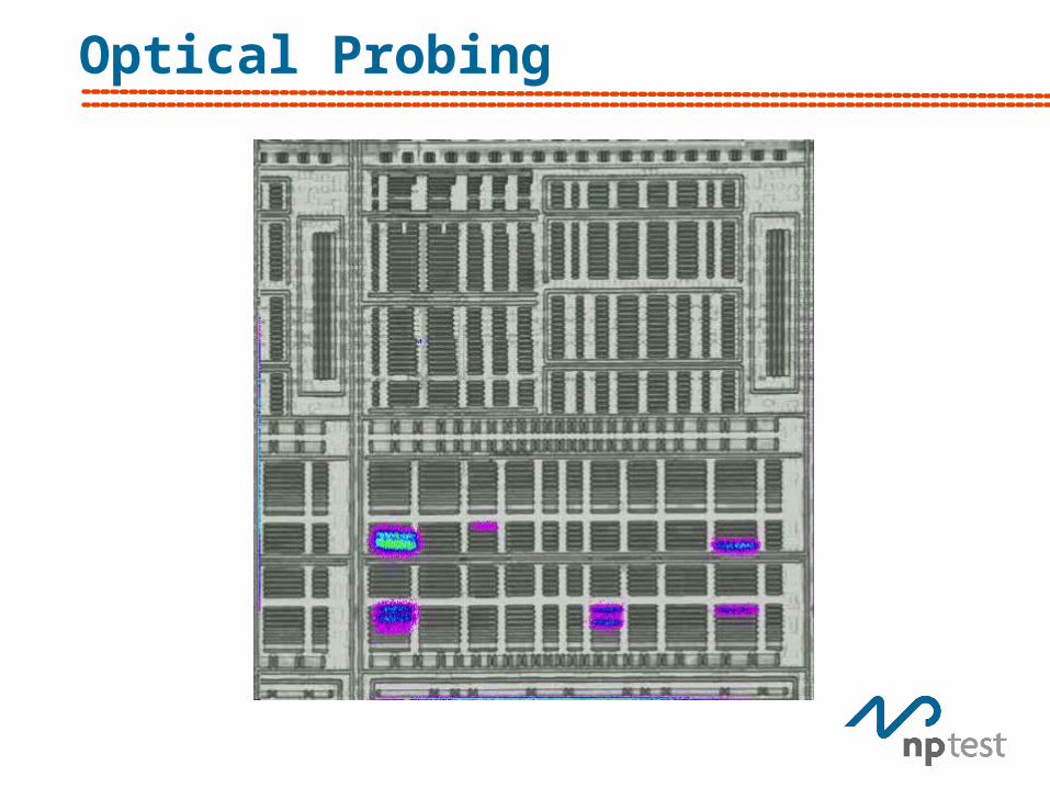
Optical Probing

Cooling System setup
DUT
Heat Exchanger
Heat Spreader, Diamond window
Clamp
Lens
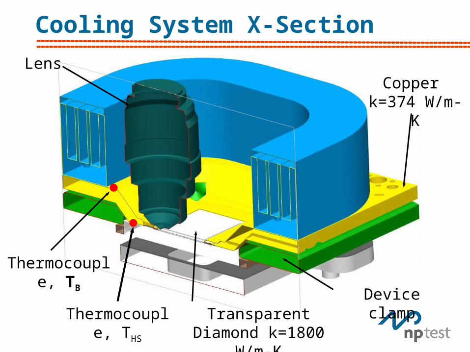
Cooling System X-Section
Transparent Diamond k=1800 W/m-K
Device clamp
Thermocouple, TB
Thermocouple, THS
LensCopper
k=374 W/m-K
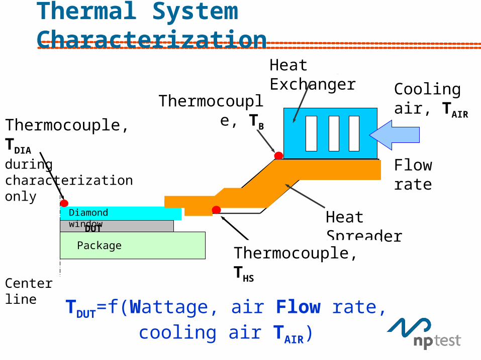
Thermal System Characterization
TDUT=f(Wattage, air Flow rate, cooling air TAIR)
Heat Spreader
Thermocouple, TDIA
during characterization only
Diamond window
Thermocouple, TB
Heat Exchanger
Thermocouple, THS
DUT
Center line
Package
Heat Exchanger
Cooling air, TAIR
Flow rate
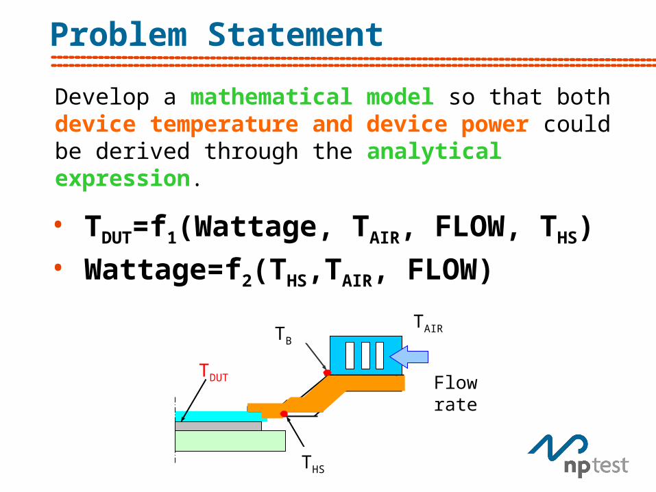
Problem Statement
Develop a mathematical model so that both device temperature and device power could be derived through the analytical expression.
TDUT
TB
THS
TAIR
Flow rate
• TDUT=f1(Wattage, TAIR, FLOW, THS)• Wattage=f2(THS,TAIR, FLOW)

Thermal System Characterization
TDIA
TB
THS
TAIR
Air Flow rate
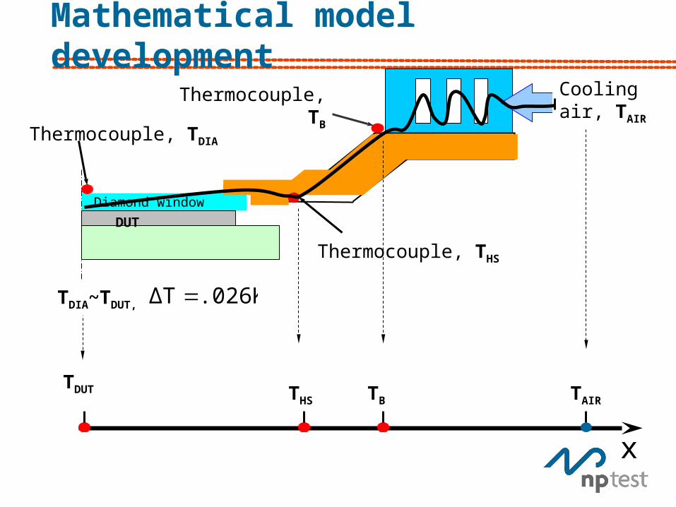
Mathematical model development
Thermocouple, TDIA
Diamond window
Thermocouple, TB
Cooling air, TAIR
Thermocouple, THS
DUT
x
TDUT THS TB TAIR
TDIA~TDUT, .026KΔT
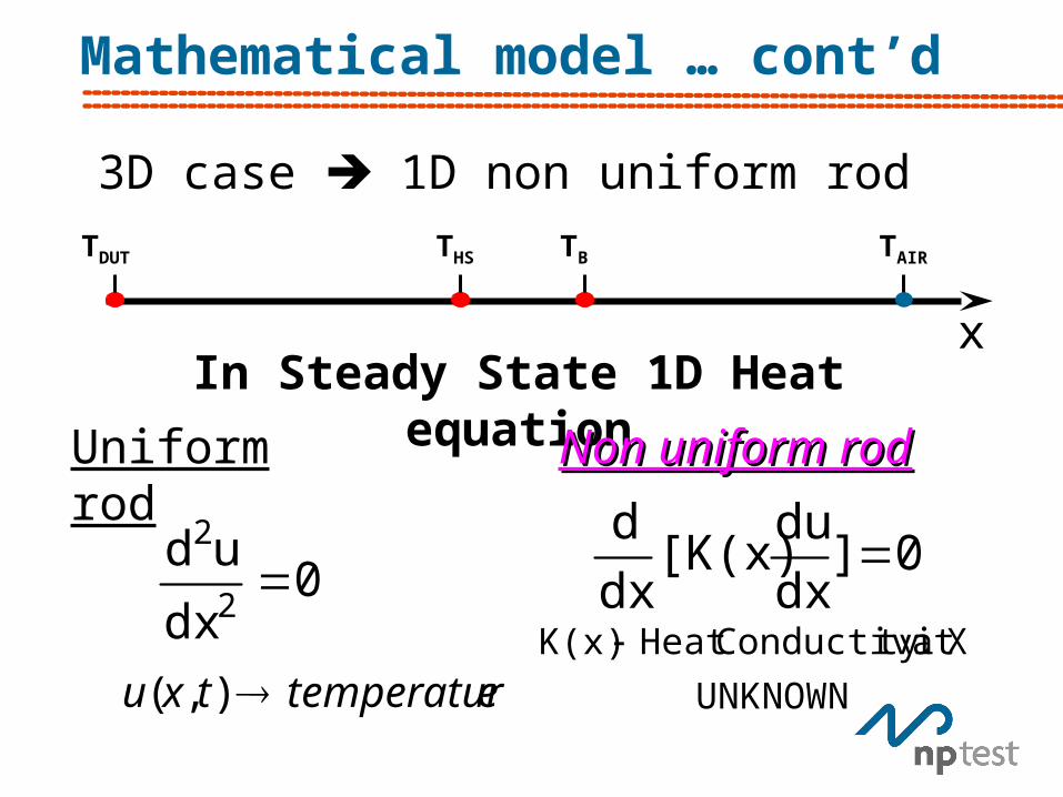
Mathematical model … cont’d
x
TDUT THS TB TAIR
3D case 1D non uniform rod
In Steady State 1D Heat equation
Uniform rod
0]dx
du[K(x)
dx
d
UNKNOWN
Xat ty ConductiviHeat K(x)
0dx
ud2
2
etemperaturtxu ),(
Non uniform rodNon uniform rod
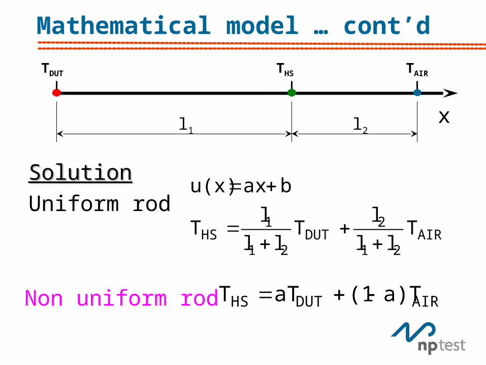
Mathematical model … cont’d
x
TDUT THS TAIR
l1 l2
SolutionSolution
Uniform rodAIR
21
2DUT
21
1HS T
ll
lT
ll
lT
baxu(x)
AIRDUTHS a)T(1aTT Non uniform rod
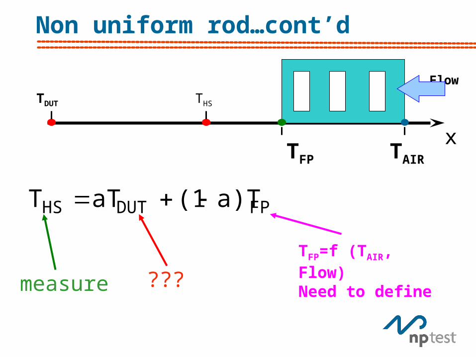
Non uniform rod…cont’d
x
TDUT THS
TAIRTFP
Flow
FPDUTHS a)T(1aTT
TFP=f (TAIR, Flow)Need to define
measure ???

TFP=f (TAIR, FLOW)
x
TDUT THS
TAIR
cTFP
d
FLOW-h3FP beTT
TFP TAIR
T3
T3
mt3FP beTT
FLOW
1t
skW FLOW-h
FP beskWT
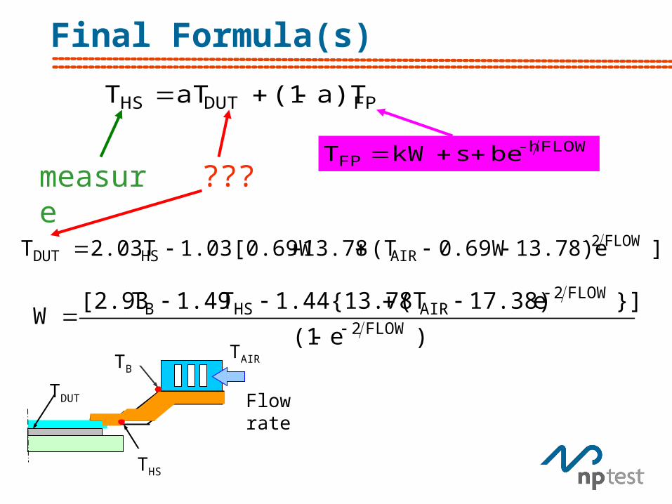
Final Formula(s)
FPDUTHS a)T(1aTT
measure
???FLOW-h
FP beskWT
)e(1
}]e 17.38)(T1.44{13.78T 1.49T [2.93W
FLOW2
FLOW2AIRHSB
]13.78)e0.69W(T13.781.03[0.69W2.03TT FLOW2AIRHSDUT
TDUT
TB
THS
TAIR
Flow rate

Results Comparison
TDUT
TB
THS
TAIR
Flow rate,
Error was less that 10% over the entire temperature and power range
Conclusions
• Cooling system for thinned 150W microprocessor - characterized
• 3-D Heat Transfer simplified to a 1-D non uniform rod case
• Device temperature and input power can be determined through an analytical expression
• Future software control capabilities.