thermodynamics dec 17 q.1(a) define heat engine
TRANSCRIPT

THERMODYNAMICS
DEC – 17
Q.1(a) Define heat engine, refrigerator and heat pump. [5]
Ans: Heat engine: It is a device which is operated in cycle it receives energy from high temperature
body, converts part of it into work and rejects rest to a low temperature body.
The primary objective of heat engine is to convert the energy as heat into work. E.g. Thermal
power plant.
Efficiency of heat engine: The efficiency of a heat engine is defined as the ratio of the Net work
done to the energy absorbed as heat.
𝑛𝐸 =𝑜𝑢𝑡𝑝𝑢𝑡
𝐼𝑛𝑝𝑢𝑡=
𝑊
𝑄1=
𝑄1 − 𝑄2
𝑄1= (𝑇1 − 𝑇2)/𝑇1
Refrigerator: refrigerator is cyclically operated device which absorb energy as heat from low
temperature body and rejects energy as heat To a high temperature body when the work is
performed on the device. The primary objective of a device is to maintain body at low temperature.
Fig

C.O.P of refrigerator: the cop of refrigerator is defined as the ratio of the heat absorbed to the
work done.
𝐶𝑂𝑃𝑅 =𝑂𝑢𝑡𝑝𝑢𝑡
𝑖𝑛𝑝𝑢𝑡=
𝑄2
𝑊=
𝑄2
𝑄2 − 𝑄1=
𝑇2
𝑇2 − 𝑇1
Heat pump: Heat pump is a cyclically operated device which absorb energy from a low
temperature body and reject energy as heat to a high temperature body. The main objective of the
heat pump is to reject energy as heat to a high temperature reservoir.
𝐶𝑂𝑃𝐻 =𝑂𝑢𝑡𝑝𝑢𝑡
𝑖𝑛𝑝𝑢𝑡=
𝑄2
𝑊=
𝑇2
𝑇2 − 𝑇1
Fig
Cop of heat pump: The cop of heat pump is defined as the ratio of the heat supplied to the work
done
.
Q.1(b) Draw a neat diagram of vane type blower and explain its working.
[5]
Ans: 1) Vane type compressor refer figure consists of a rotor mounted eccentrically in the body
and supported by ball and roller bearing at the ends.
2) The rotor is slaughtered to take the blades which are of a non-metallic material usually fibre or
carbon. Each blade moves past the Indian passage compression begins due to decreasing volume
between the rotor and casing.
3) Delivery begins with the arrival of each blade at the delivery passage. PV diagram is shown in
the figure b where V induced volume at state P1 n T1. Compression occurs to the pressure P1
isentropic ally. At this pressure the displays gas is open to the receiver and the gas flowing back

from the receiver rises the pressure irreversibly to p2. The work input is given by the sum of areas
a and b.
Fig: vane type positive displacement compressor with PV diagram.
Q.1(c) Define 1) wet steam 2) superheated steam 3) dryness fraction 4) saturation
temperature [5]
Ans: 1) wet steam: The steam in the steam space of a boiler generally contains water mixed with
it in the form of a mist (fine water particles). Such a steam is termed as wet steam.
2)Superheated steam: if the water is entirely evaporated and further heat is then supplied the first
effect on the steam is to make it dry if it is not already dry the temperature of steam will then begin
to increase with the corresponding increase in volume.
steam in this condition heated out of contact with water is said to be superheated. Superheating is
assumed to take place at constant pressure the amount of superheating is measured by the rise in
temperature of the steam above its saturation temperature TS greater the amount of superheating
the more will the steam acquire the properties of a perfect gas.
3) Dryness fraction: The quality of steam as regards iTs dryness is termed as dryness fraction.
Dryness fraction is usually expressed by the symbol 'x'.
Dryness fraction is often spoken as a quality of wet steam.
If Ms = mass of dry steam contained in the steam considered
M = mass of water in suspension in the steam considered.
X = 𝑀𝑆
𝑀𝑆+𝑀
Thus, if dryness fraction of wet steam x = 0.8 then 1 kg of wet steam contains 0.2 kg of moisture
(water) in suspension and 0.8 kg of dry steam.

4) saturation temperature: It is the maximum temperature corresponding to a given pressure at
which a substance can exist in liquid form.
when a liquid and its vapour are in equilibrium at a certain pressure and temperature, only the
pressure of the temperature is sufficient to identify the saturation state.
If the pressure is given the temperature of the given fixture get fixed, which is known as saturation
temperature.
Q.1(d) what do you understand by mean temperature of heat addition? For a given
temperature of heat rejection show how the Rankine cycle efficiency depends on the main
temperature o the heat addition. [10]
Ans: In the Rankine cycle heat is added reversibly at constant pressure but at infinite temperatures.
If Tm1 is the mean temperature of heat addition, as shown in the figure show that area under 4S
and 1 is equal to the area under 5 and 6, then heat added.
Q= h1 – h4 =Tm1 (S1-S4)
Tm1 = mean temperature of heat addition
= ℎ1−ℎ4𝑠
𝑠1−𝑠4𝑠
Since Q2= Heat rejected = h2S – h3
= T2 (S1-S4S)
Efficiency of Rankine Rankine = 1 - 𝑄2
𝑄1= 1 −
𝑇2(𝑆1−𝑆4)
𝑇𝑀1(𝑆1−𝑆4)
𝑅𝑎𝑛𝑘𝑖𝑛𝑒
= 1 − (𝑇2
𝑇𝑀𝐿) (1)
Where T2 is the temperature of heat rejection. Then lower is the T2 for a given TM1, the higher will
be the efficiency of Rankine cycle. But the lowest practicable temperature of heat rejection is the
temperature of the surroundings T0. This being fixed.
Efficiency of Rankine. = F(TM1) only
The higher the mean temperature of heat addition, the higher will be the cycle efficiency.

Q.1(e) state the first law for a closed system undergoing a change of state.
[5]
Ans: The expression (W)cycle= (Q)CYCLE applies only to the system undergoing cycles and
algebraic summation of all energy transfer across system boundaries is zero.
But if a system undergoes a change of state during which both heat transfer and work transfer are
involved, the net energy transfer will be sorted or accumulated within the system.
If Q is the amount of heat transfer to the system and W is the amount of work transfer from the
system during the process figure 1, the net energy transfer (Q-W) will be sorted in the system.
Energy in storage is neither heat nor work energy given the name internal energy or simply energy
system.
Therefore, Q - W = ΔE
Where E is the increase in the energy of the system
Or Q = ΔE + W (1)
Near Q, W and ΔE are all expressed in the same units in joules energy may be sorted by a system
in different modes.
If there are more energy transfer quantities involved in the process as shown in figure 2, the first
law gives,
(Q12+Q3-Q1) = ΔE + (W2+W3-W1-W4)
Energy is conserved in the Operation. The first law is a particular formulation of the principle of
the conservation of energy.
Equation 1 may be also considered as the definition of energy. This definition does not give an
absolute value of energy E, but only the change of energy for the process. It can however be shown
that the energy has a definite value at every state of no system and is therefore a property of the
system.

Q.2(a). Reciprocating air compressor text in 3 m3/min 0.11 MPa, 20°C which it delivers at
1.5 MPa, 111° C to an after cooler where the air is cooled at constant pressure to 25°C. The
power absorbed by the compressor is 4.15 KW. Determine the heat transfer in the
compressor and the after cooler. [10]
Ans:. V1 = 2 m3/min= 2/60 = 0.33 m3/s
P1 = 0.11 MPa P2 = 1.5 MPa
T1 = 20°C T2 = 111°C T3 = 25°C
Power absorbed by the compressor W = 4.15 KW
Mass flow rate of air using ideal gas equation
P1V1 = m R T1
110 x 0.033 = m x 0.287 x 293
M = 0.0432 to kg/s
Applying steady flow energy equation at compressor
Q+m ℎ1 + (𝑉1
2
2000) + 𝑔𝑧1 = 𝑤 + 𝑚 (ℎ2 + (
𝑉22
2000) + 𝑔𝑧2
Here KE= PE= 0
Q= m (h2 – h1) + W
= W+ m CP (T2-T1)
= (4.15) + (0.04 32 x 1.005 (384 – 293)
= 8.10 KW
Applying steady flow energy equation at aftercooler
Q+ m ℎ2 + (𝑉2
2
2000) + 𝑔𝑧2 = 𝑤 + 𝑚 (ℎ3 + (
𝑉32
2000) + 𝑔𝑧3
Your KE = PE= W = 0
Q= m (h3 – h2)
= m Cp ( T3 –T2 )
= 0.04 32 x 1.005 x (298 – 384)
Q = -3.73 KW
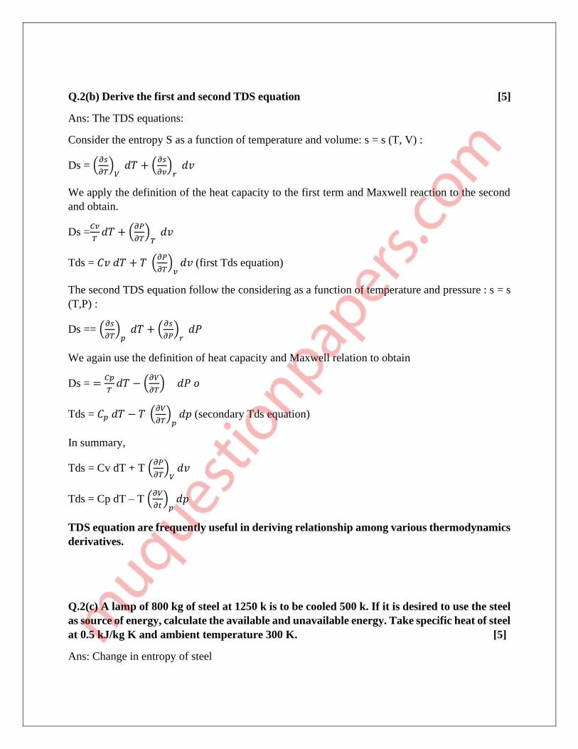
Q.2(b) Derive the first and second TDS equation [5]
Ans: The TDS equations:
Consider the entropy S as a function of temperature and volume: s = s (T, V) :
Ds = (𝜕𝑠
𝜕𝑇)
𝑉 𝑑𝑇 + (
𝜕𝑠
𝜕𝑣)
𝑟 𝑑𝑣
We apply the definition of the heat capacity to the first term and Maxwell reaction to the second
and obtain.
Ds =𝐶𝑣
𝑇𝑑𝑇 + (
𝜕𝑃
𝜕𝑇)
𝑇 𝑑𝑣
Tds = 𝐶𝑣 𝑑𝑇 + 𝑇 (𝜕𝑃
𝜕𝑇)
𝑣𝑑𝑣 (first Tds equation)
The second TDS equation follow the considering as a function of temperature and pressure : s = s
(T,P) :
Ds == (𝜕𝑠
𝜕𝑇)
𝑝 𝑑𝑇 + (
𝜕𝑠
𝜕𝑃)
𝑟 𝑑𝑃
We again use the definition of heat capacity and Maxwell relation to obtain
Ds = =𝐶𝑝
𝑇𝑑𝑇 − (
𝜕𝑉
𝜕𝑇) 𝑑𝑃 𝑜
Tds = 𝐶𝑝 𝑑𝑇 − 𝑇 (𝜕𝑉
𝜕𝑇)
𝑝𝑑𝑝 (secondary Tds equation)
In summary,
Tds = Cv dT + T (𝜕𝑃
𝜕𝑇)
𝑉𝑑𝑣
Tds = Cp dT – T (𝜕𝑉
𝜕𝑡)
𝑝𝑑𝑝
TDS equation are frequently useful in deriving relationship among various thermodynamics
derivatives.
Q.2(c) A lamp of 800 kg of steel at 1250 k is to be cooled 500 k. If it is desired to use the steel
as source of energy, calculate the available and unavailable energy. Take specific heat of steel
at 0.5 kJ/kg K and ambient temperature 300 K. [5]
Ans: Change in entropy of steel

ΔS = M .Cp .ln (𝑇2
𝑇1) = 800 x 0.5 x ln (500/1250) = -36.5 16 kJ/k
• Available energy = Q – T0 (ΔS)
= M Cp (T1- T2) – T0 (ΔS)
= 800 x 0.5 x (1250 – 500) – (300 X 36.516)
= 19 0.045 mJ
• Unavailable energy = T0 (ΔS) = 300 X 36.5 16
= 109.95 mJ
Q.3 (a)A heat pump working on a Carnot cycle takes in heat from a reservoir at 5°C and
delivers heat to reservoir at 60°C. The head pump is driven by a reversible heat engine which
takes in lead from a reservoir at 840 and rejects heat reservoir at 60°C. Reversible heat
engine also drives a machine that absorbs 30 KW. If the pump extract 17 kJ/s from the 5°C
reservoir, determine :
1) the rate of heat supply from 840°C source
2) the rate of heat rejection at 60°c sink. [10]
Ans: we know Carnot c o p of heat pump
COP = 𝑇2
𝑇2−𝑇1
= 333
333−278
= 6.055
ALSO C.O.P = ℎ𝑒𝑎𝑡 𝑟𝑒𝑗𝑒𝑐𝑡𝑒𝑑
𝑤𝑜𝑟𝑘 𝑠𝑢𝑝𝑝𝑙𝑖𝑒𝑑
6.055 = 𝑄𝑅
𝑄𝑅−𝑄𝑆=
𝑄𝑅
𝑄𝑅−17
QR = 20.195 kW
Applying first law at heat pump
Heat supplied = heat rejected
Wnet + QS = QR
Wnet = QR + QS = 20.1 97 – 17 = 3.195 kW
Now the total work output of reversible heat engine
= (W net to heat pump) + (W net to external machine)
= 3.1 95 + 30 = 33.1 95 KW

Now efficiency of reversible heat engine is given by
HE = 𝑇1−𝑇2
𝑇1=
1113−333
1113= 0.7008 = 70.08 %
Also HE = 𝑄𝑆−𝑄𝑅
𝑄𝑆
0.7 008 = 33.195
𝑄𝑆
QS = 47.37 KW
QS - QR = W Net
Qr = Qs – Wnet
= 47. 37 – 33. 195
= 14.175 KW
Total heat rejected
= (QR)HP +(QR)HE
=14.175 + 20.195
=3 4.37 Kw
Q.3 (b) determine entropy change of universe, if two copper blocks of 1 kilogram and 0.5
kilogram at 150°C and 0°C joined together. Specific heats for copper at 150°C and 0°C are
0.393 kJ/kg and 0.38 1 kJ/kg K respectively. [5]
Ans : Here ΔS universe = ΔS block 1 +ΔS block 2
Two blocks at different temperatures shall first attain equilibrium temperature. Let equilibrium
temperature be TF
1 x 0.39 3 x (42 3.15 – TF) = 0.5 x 0.381 x (TS x 273.15)
TF = 37 4.19 k
Entropy change in block 1 due to temperature changing from 423.15 k to 2374.19 k
ΔS1 = 1 x 0.393 x ln (374.19
423.15) = −0.0483 𝑘𝑗/𝑘
Entropy change in block 2
ΔS2 = 0.5 x 0.381 x In(374.19
273.15)

= 0.0 599 kJ/k
Entropy change of universe
ΔS universe = ΔS1 + ΔS2 = 0.05 99 - 0.04 83
= 0.0116 kJ K
Q.3(c) determine the maximum work obtainable by using of finite body at temperature t and
thermal energy reservoir at temperature T0, T > T0 [5]
Ans : let one of the body is consider in the previous section b a thermal energy reservoir.
The finite body and body has a thermal capacity CP and is at temperature T and TER is at
temperature T, Such that T > T0.
Let a heat engine operates between the two refer figure. is withdrawn from the body is temperature
decreases. the temperature of the TER would however remain unchanged at T0
Danger full stop working in the temperature of the body reaches to T0. During that period the
amount of work deliver is w, and heat rejected to the t e r is (Q-W).
Then It is called energy of the finite body at temperature T.
Q.4(a) cycle steam power plant is to be designed for a steam temperature at turbine inlet of
360° and exhaust pressure of 0.08 bar. After isentropic expansion of steam in the turbine the
moisture content determine exhaust is not to exceed 15%. Determine the greatest allowable
steam pressure and turbine inlet and calculate the Rankine cycle efficiency for this steam
conditions. Estimate also the mean temperature of heat addition.
[10]
Ans: as state 2s (refer figure) quality and pressure are known

S2s = Sf + X2s Sfg
= 0.5926 + 0.85 (8.2 287 - 0.5926)
=7.0833 kJ/kg k
Since s1 = S2s
S1 = 7.0833 kJ / kg k
At state 1, the temperature and entropy are thus known. At 360°C Sg = 5.0526 kJ / kg k which is
less than S1. So from the table of superheated steam at T1 = 360 and S1 = 7.0 833 kJ/kg k the
pressure is found to be 16.832 bar (by interpolation).
The greatest allowable steam pressure is
P1= 16.8 32 bar
H1 = 316 5.54 kJ/kg
H2s = 17 3.88 + 0.85 X 240 3.1 = 2216.52 kJ/kg
H3 = 173.8 kJ/kg
H4 – H3 = 0.001 x (16.83 - 0.08) X 100 = 1.675 kJ / kg
H4s = 17.5 61 kJ/kg
Q1 = h1- h4 = 316 5.5 4 – 17 5.56 = 2990 kJ/ kg
Wt = h1 – h2s = 316 5.5 4 - 221 6.52 = 949 kJ / kg
Wp= 1.675kJ/kg

Ncycle = 𝑤𝑛𝑒𝑡
𝑄1= (
947.32
2990) = 0.3168
Mean temperature of heat addition
Tm1 = 𝒉𝟏−𝒉𝟒𝒔
𝒔𝟏−𝒔𝟒𝒔=
𝟐𝟗𝟗𝟎
𝟕.𝟎𝟖𝟑𝟑−𝟎.𝟓𝟐𝟗𝟔= 𝟒𝟔𝟎. 𝟔𝟔 𝒌 = 187.51°C
Q.4(b) derive an expression for air standard efficiency for Otto cycle.
[10]
Ans : Otto cycle: the main drawback of carnot cycle is its impractically due to high pressure and
high volume ratio employed with comparatively low mean effective pressure.
Nicholas auto 1876 first propose a constant volume heat addition cycle which forms a basis for
working of today's spark ignition engines.
Process 1 to 2 : reversible adiabatic compression of air when piston moves upward.
Process 2 to 3 : reversible constant volume heat addition
Process 3 to 4 : reversible adiabatic expansion
Process 4 to 1 : reversible constant volume heat rejection.
Air standard efficiency:
Compression ratio: it is defined as the ratio of volume at the beginning of the compression to the
volume at the end of the compression.
rK = 𝑣𝑜𝑙𝑚𝑒 𝑎𝑡 𝑡ℎ𝑒 𝑏𝑒𝑔𝑖𝑛𝑖𝑛𝑔 𝑜𝑓 𝑡ℎ𝑒 𝑐𝑜𝑚𝑝𝑟𝑒𝑠𝑠𝑖𝑜𝑛
𝑣𝑜𝑙𝑢𝑚𝑒 𝑎𝑡 𝑡ℎ𝑒 𝑒𝑛𝑑 𝑜𝑓 𝑡ℎ𝑒 𝑐𝑜𝑚𝑝𝑟𝑒𝑠𝑠𝑖𝑜𝑛= (
𝑉1
𝑉2)
Thermal efficiency of Otto cycle can be written as
OTTO = 𝑄1−𝑄2
𝑄1= 1 −
𝑄2
𝑄1

Let m be the fixed mass of air undergoing the cycle,
Heat supplied, Q(2-3) = Q1 = m Cv. (T3 – T2)
Heat rejected, Q(4-1) = Q2 = m Cv. (T4 – T1)
Insufficiency can be given as
otto = 1 −𝑄2
𝑄1= 1 −
𝑚.𝐶𝑣.(𝑇4−𝑇1)
𝑚.𝐶𝑣.(𝑇3−𝑇2)= 1 −
𝑇4−𝑇1
𝑇3−𝑇2 V
Process 1 to 2, 𝑇2
𝑇1= (
𝑉1
𝑉2)
𝑟−1
Or 𝑇2 = 𝑇1 (𝑉1
𝑉2)
𝑟−1
Process 3 to 4, 𝑇3
𝑇4= (
𝑉4
𝑉3)
𝑟−1
= (𝑉1
𝑉2)
𝑟−1
Or 𝑇3 = 𝑇4 (𝑉1
𝑉2)
𝑟−1
Putting the value of T2 and T3 in equation 1
OTTO = 𝟏 −𝑻𝟒−𝑻𝟏
𝑻𝟑−𝑻𝟐= 𝟏 −
𝑻𝟒−𝑻𝟏
𝑻𝟒(𝑽𝟏𝑽𝟐
)𝒓−𝟏
−𝑻𝟏(𝑽𝟏𝑽𝟐
)𝒓−𝟏 = 𝟏 −
𝟏
𝒓𝑲𝒓−𝟏
Q.4(c) Define volumetric efficiency of a compressor. On what factors does it depend?
[5]
Ans: The amount of air deals with in a given time by an air compressor is often referred at free air
conditions, eg the temperature and pressure of the environment which made taken as 15°C and
101.325 KPa, if not mentioned.
It is known as free air delivery (FAD). The ratio of the actual volume of gas taken into the cylinder
during suction stroke to the piston displacement volume of the swept volume (vs) of the piston is
called volumetric efficiency, or
vol =𝑚𝑣1
𝑃𝐷=
𝑚𝑣1
𝑣𝑠
Where m is the mass flow rate of the gas and v1 is the specific volume of the gas inlet to the
compressor. Reference to figure 1.
vol = 𝑉2−𝑉1
𝑉𝑆=
𝑉𝐶+𝑉𝑆−𝑉1
𝑉𝑆
=1 + (𝑉𝐶
𝑉𝑆) − (
𝑉1
𝑉𝑆)

Let C = clearance = 𝐶𝐿𝐸𝐴𝑅𝐴𝑁𝐶𝐸 𝑉𝑂𝐿𝑈𝑀𝐸
𝑃𝐷 𝑜𝑟 𝑉𝑠
= 𝑉𝐶
𝑉𝑆
Since 𝑃1𝑉1𝑛 = 𝑃2𝑉4
𝑛
𝑣1 = 𝑣4 (𝑝2
𝑝1)
1
𝑛= 𝑣𝑐 (
𝑝2
𝑝1)
1
𝑛
𝑣𝑜𝑙
= 1 + 𝐶 − (𝑣𝑐
𝑣𝑠) (
𝑝2
𝑝1)
1
𝑛
= 1 + 𝐶 − 𝐶 (𝑝2
𝑝1)
1
𝑛 (1)
Equation 1 plotted in figure 2 two Sins (p2/p1) is always greater than unity, it is evident that the
volumetric efficiency decrease as a clearance increases and as the pressure ratio increases.
In order to get maximum flow capacity, compressor are built with the minimum practical
clearance. Sometimes however the clearance is deliberately increase (𝑚 =𝑣𝑠𝑛𝑣
𝑣1) as a means of
controlling the flow through a compressor driven by a constant speed motor.
The compressor cylinder in figure is fitted with the clearance pocket which can be opened by a
valve.
Let us suppose that this machine is operating at conditions corresponding to line in figure if the
clearance volume is at minimum value at the volumetric efficiency and flow through the machine
are maximum.
Clearance pocket is then opened to increase a clearance to b, the volumetric efficiency and the
flow are reduced. By increasing the clearance in steps as indicated by point c and d, the flow may
be reduced in steps to zero

The work per kilogram of gas compressed is, however, not affected by the clearance volume in an
idealized compressor.
For a given pressure ratio n is zero when maximum clearance is
Cmax = 1
((𝑝2𝑝1
))
1𝑛
−1
Following factors affect the volumetric efficiency of air compressor:
1) Clearance between the piston of TDC and cylinder cover. Larger the clearance lesser the
air discharge per stroke and lesser will be the volumetric efficiency of air compressor.
2) Sluggish operation of valves.
3) Lealcy piston rings
4) Ineffective cooling due to choking of inter after cooler for lack of water supply.
5) High temperature of air at suction of 1st stage and dirty air filters.
Q.5(a) A mass of air is initially at 260°C and 700 kPa and occupies 0.028 m3. The air is
expanded at constant pressure to 0.084 m3. Polytrophic process with n is = 1.50 is then carried
out, followed by a constant temperature process which completes the cycle. All the process
is reversible [10]
1) sketch the cycle on PV and TS plane.
2) find the heat received and heat rejected in the cycle
3) find efficiency of the cycle.
Ans : P1 = 700 Kpa T1 = 260 + 273 = 533 k
V1 = 0.028 m V2 = 0.084 m3
We have P1V1 = mRT1

m = 700×0.028
0.287×533= 0.128 kg
now, 𝑇2
𝑇1= (
𝑝2𝑣2
𝑝1𝑣1) = (
0.084
0.027) = 3
therefore 𝑇2 = 3 × 533 = 1559 k
Again 𝑝2
𝑝3= (
𝑇2
𝑇3)
𝑛
𝑛−1
= (1599
533)
1.5
0.5= 33 = 27
𝑝3 = (𝑝2
27) = (
700
27) = 25.93 𝑘𝑝𝑎
Heat transfer in process 1 to 2
𝑄1−2 = 𝑚𝐶𝑃(𝑇2 − 𝑇1)
=0.128 × 1.005(1599 − 533)
=137.13 KJ
Heat transfer in process 2-3
𝑄2−3 = 𝛥𝑈 + ∫ 𝑃𝑑𝑣
= 𝑚𝐶𝑣(𝑇3 − 𝑇2) +𝑚𝑅(𝑇2−𝑇3)
𝑛−1
𝑄2−3 = 𝑚 𝐶𝑣𝑛−𝑦
𝑛−1(𝑇3 − 𝑇2)
𝑄2−3 = 0.128 × 0.718 ×1.5−1.4
1.5−1. (533 − 1599)
= -19.59 Kj
Process 3-1
𝑄3−1 − 𝑑𝑈 + 𝑤3−1
But Du = 0 – (ISOTHERMAL PROCESS)
𝑊3−1 = ∫ 𝑝𝑑𝑣1
3= 𝑚𝑅𝑇1 𝐼𝑛 (
𝑣1
𝑣3) = 𝑚𝑅𝑇1 𝐼𝑛 (
𝑝3
𝑝1)
=0.128 × 0.287 × 533 × 𝐿𝑛 (25.93
700)
= -64.53 kJ
1) Heat received in the cycle Qs = 137.13 = kJ
2) Heat rejected in the cycle QR = 19.5 9 + 64.5 3 = 84.12 lJ
3) Efficiency of the cycle

𝑐𝑦𝑐𝑙𝑒
=𝑄𝑠−𝑄𝑟
𝑄𝑠=
137.13−84.12
137.13= 38.66%
Q.5(b) Q.1(c) show that energy is a property of a system. [5]
Ans: Energy - A property of a system
Fig(a)
Consider a system which changes its state from state 1 to state 2 by following the path A, and the
returns from state 2 to state 1 by following the path B (refer fig (a)). so the system undergoes a
cycle. Writing the first or path A
QA = ΔEΔ+ WA (1)
For path
QB = ΔEB +WB (2)
The process A and B together constitute a cycle, for which
(∑ 𝑊)CYCLE = (∑ 𝑄)CYCLE
OR WA + WB = QA+QB
OR QA - WA = WB-QB (3)
From eq (1), (2) and (3) its yields
ΔEA = -ΔEB (4)
Similarly, had the system returned from the state 2 to state 1 but following the path C instead of
path B

ΔEA = -ΔEC (5)
From eq (4) and (5)
ΔEB =ΔEC (6)
Therefore, it is seen that the change in energy between two states of a system is the same, whatever
the path the system may follow in undergoing that change of state. If some arbitrary value of
energy is assigned to state 2 the value of energy at state 1 is fixed independent of the path the
system follows. Therefore, energy has a definite value of energy state of the system. Hence it is a
point function and a property of the system
The energy E is an extensive property. The specific energy, e = E/m (j/kg). is an extensive property.
The cyclic integral of any property is zero, because the final state is identical with the initial state.
Q.5(c) Write Maxwell’s equations. [5]
Ans: A pure substance existing in single phase has only two independent variables of the 8
quantities P, V, T, S, U, H, F (Helmholtz function|) and G (Gibbs function) anyone may be
expressed as a function of any two others.
If dz = m. dx + N. dy then, (𝜕𝑀
𝜕𝑌)
𝑋= (
𝜕𝑁
𝜕𝑋)
𝑌
For a pure substance undergoing an infinitesimal reversible process,
1. dU = T. dS – p. dV
since U is thermodynamic property of exact differentials.
(𝝏𝑻
𝝏𝑽)
𝒔= (
𝝏𝒑
𝝏𝑺)
𝑽
2. dH = dU + p. dv + V. dp = T. ds + V. dp
since H Is thermodynamics property of exact differentials,
(𝝏𝑻
𝝏𝒑)
𝑺
= (𝝏𝒗
𝝏𝑺)
𝑷
3. dF = dU-T. dS – S. dT = -P. dV – S. dT
since F is the thermodynamics property of exact differentials,
(𝝏𝒑
𝑻)
𝑽= (
𝝏𝑺
𝝏𝑽)
𝑻
4. dG = dH – T. dS – S. dT = V. dp – S. dt
Since G is the thermodynamics property of exact differentials,
(𝝏𝑽
𝝏𝑻)
𝑷= (
𝝏𝑺
𝝏𝒑)
𝑻
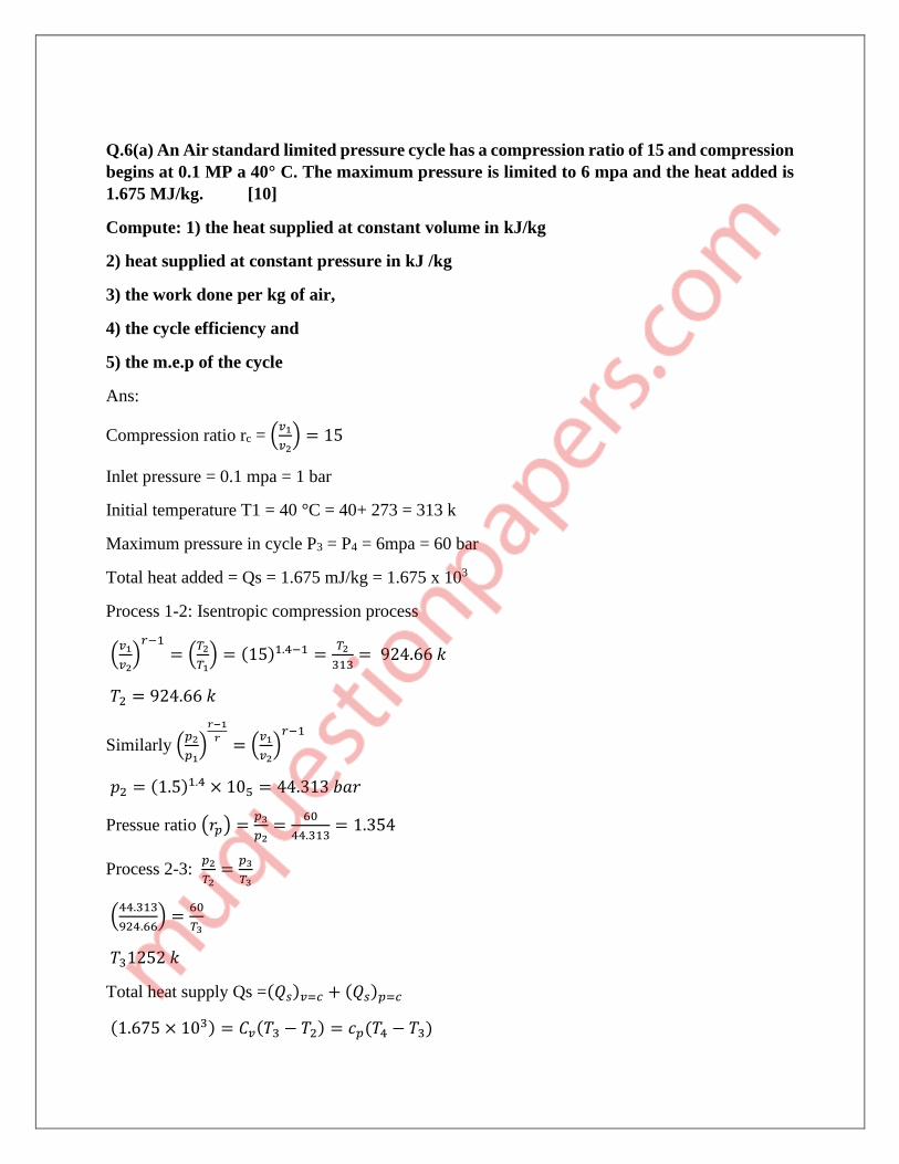
Q.6(a) An Air standard limited pressure cycle has a compression ratio of 15 and compression
begins at 0.1 MP a 40° C. The maximum pressure is limited to 6 mpa and the heat added is
1.675 MJ/kg. [10]
Compute: 1) the heat supplied at constant volume in kJ/kg
2) heat supplied at constant pressure in kJ /kg
3) the work done per kg of air,
4) the cycle efficiency and
5) the m.e.p of the cycle
Ans:
Compression ratio rc = (𝑣1
𝑣2) = 15
Inlet pressure = 0.1 mpa = 1 bar
Initial temperature T1 = 40 °C = 40+ 273 = 313 k
Maximum pressure in cycle P3 = P4 = 6mpa = 60 bar
Total heat added = Qs = 1.675 mJ/kg = 1.675 x 10³
Process 1-2: Isentropic compression process
(𝑣1
𝑣2)
𝑟−1
= (𝑇2
𝑇1) = (15)1.4−1 =
𝑇2
313= 924.66 𝑘
𝑇2 = 924.66 𝑘
Similarly (𝑝2
𝑝1)
𝑟−1
𝑟= (
𝑣1
𝑣2)
𝑟−1
𝑝2 = (1.5)1.4 × 105 = 44.313 𝑏𝑎𝑟
Pressue ratio (𝑟𝑝) =𝑝3
𝑝2=
60
44.313= 1.354
Process 2-3: 𝑝2
𝑇2=
𝑝3
𝑇3
(44.313
924.66) =
60
𝑇3
𝑇31252 𝑘
Total heat supply Qs =(𝑄𝑠)𝑣=𝑐 + (𝑄𝑠)𝑝=𝑐
(1.675 × 10³) = 𝐶𝑣(𝑇3 − 𝑇2) = 𝑐𝑝(𝑇4 − 𝑇3)

𝑻𝟒 = 𝟐𝟔𝟗𝟕𝟗. 𝟖𝟑 𝒌
Process 4-5: 𝑉3
𝑉4=
𝑇3
𝑇4
𝑉3
𝑉4= (
1252
2679.83) = 0.467
𝒄𝒖𝒕 𝒐𝒇𝒇𝒓𝒂𝒕𝒊𝒐 (𝒔) = ( 𝑽𝟒
𝑽𝟑) = 𝟐. 𝟏𝟒
Process 5-1 :
We know that re = expansion ratio = 𝑉5
𝑉4
𝑟𝑒 = 𝑉5
𝑉4=
𝑟𝑐
𝑠=
156
2.14= 7
𝑟𝑒 = 𝑉5
𝑉4= 7
Now, (𝑉5
𝑉4)
(1.4−1)
= (𝑇5
𝑇4)
𝑇𝑆 = (2679.83
(7)0.4 ) = 1230.46 𝐾
Heat supplied at constant volume
(𝑄𝑆)𝑉=𝐶 = 𝑐𝑉(𝑇3 − 𝑇2) = 0.718(1252 − 924.66)
= 235.03KJ/KG
Heat supplied at constant pressure
(𝑄𝑆)𝑃=𝐶 = 𝑐𝑃(𝑇4 − 𝑇3) = 1.005(2673.83 − 1252)
= 1434.97 KJ/KG
Work done: (𝑄𝑆)𝑉=𝐶 + (𝑄𝑆)𝑃=𝐶 − (𝑄𝑅)𝑉=𝐶
Heat rejected
(𝑄𝑅)𝑉=𝐶 = 𝐶𝑉(𝑇5 − 𝑇1) = 0.718(1230.46 − 313) = 658.736𝐾𝐽
𝐾𝐺
𝑊. 𝐷 = (235.03 + 1434.97) − (658.736)
𝑾. 𝑫 = 𝟏𝟎𝟏𝟏. 𝟐𝟔𝟒 𝑲𝑱/𝑲𝑮
Cycle efficiency: 𝑊𝐷
𝑄𝑆
𝟏𝟎𝟏𝟏.𝟐𝟔𝟒
𝟏.𝟔𝟕𝟓×𝟏𝟎𝟑= 𝟎. 𝟔𝟎𝟑𝟕%

MEP: 𝑃1[𝑌. 𝑟𝑝. 𝑟𝑐𝑦( − 1) + 𝑟𝑐
𝑦(𝑟𝑝 − 1) − 𝑟𝑐(𝑟𝑝. 𝑦 − 1)]/( − 1) × (𝑟𝑐 − 1)
= (105)[1.4 × 1.354 × 151.4(2.14 − 1) + 151.4(1.354 − 1) − 1.5(1.354 × 2.141.4 − 1)]/
(1.4 − 1) × |(15 − 1)
= 18.756 bar
Q.6 (b) single stage double acting air compressor is required to deliver 14 mm of air per
minute measured at 1.013 bar and 15 C. The delivery pressure is 7 bar and the speed 300
rev/min. Take the clearance volume at 5% of the swept volume with compression and re
expansion index of n = 1.3.
Calculate the swipe volume of the cylinder delivery temperature and the indicated power.
[10]
Ans : swept volume, 𝑣𝑠 = 𝑣𝑎 − 𝑣𝑐
Here 𝑣𝑎 = 1.05 𝑣𝑠
𝑣𝑐 = 0.05 𝑣𝑠
Volume induced cycle per cycle
(𝑣𝑎 − 𝑣𝑑) = 14 𝑚3/𝑚𝑖𝑛
= (14
300 (𝑟𝑒𝑣
min)×2
= 0.023𝑚3/𝑐𝑦𝑐𝑙𝑒
We know, 𝑣𝑑
𝑣𝑐= (
𝑝2
𝑝1)
1
𝑛
𝑣𝑑 = 𝑣𝑐 (𝑝2
𝑝1)
1
𝑛= 0.05𝑣𝑠 (
7
10.13)
1
1.3
𝑣𝑑0.221 𝑣𝑠
(𝑣𝑎 − 𝑣𝑑) = 10.05 𝑣𝑠 − 0.221 𝑣𝑠
= 0.8288 vs
From 1we get
0.8288 𝑣𝑠 = 0.023
𝒗𝒔 = 𝟎. 𝟎𝟐𝟖𝒎𝟑
Swipe volume (𝑣𝑠)0.0285 𝑚3
We also have

(𝑇2
𝑇1) = (
𝑃2
𝑃1)
𝑛−1
𝑛
𝑇2 = 𝑇1 (𝑃2
𝑃1)
(𝑛−1)
𝑛
= 288 (7
1.013)
0.3
1.3
𝑡2 = 4502 𝑘
Delivery temperature T2 = 450 k
Indicated power (IP)
𝐼𝑃 = (𝑛
𝑛−1) 𝑝1𝑣 {(
𝑝2
𝑝1)
𝑛−1
𝑛− 1}
(1.3
1.3−∗1) × 1.013 × 105 {(
7
1.013)
0.3
1.3− 1}
= 5758.52 W
IP = 57.58 kw