thermostatic all-in-one power shower...
TRANSCRIPT

11111THESE INSTRUCTIONS ARE TO BE LEFT WITH THE USERTHESE INSTRUCTIONS ARE TO BE LEFT WITH THE USERTHESE INSTRUCTIONS ARE TO BE LEFT WITH THE USERTHESE INSTRUCTIONS ARE TO BE LEFT WITH THE USERTHESE INSTRUCTIONS ARE TO BE LEFT WITH THE USER
Thermost
atic
Thermost
atic
Thermost
atic
Thermost
atic
Thermost
atic
ALL-IN-ONE
Maintenance Guide
Operation &B
POWER SHOWER
Installation
THERMOSTATIC

ContentsContentsContentsContentsContentsSectionSectionSectionSectionSection PagePagePagePagePage
1 ..... IntroductionIntroductionIntroductionIntroductionIntroduction ................................................................... 4
2 ..... Important Safety InformationImportant Safety InformationImportant Safety InformationImportant Safety InformationImportant Safety Information........................................... 5
3 ..... Pack Contents ChecklistPack Contents ChecklistPack Contents ChecklistPack Contents ChecklistPack Contents Checklist .................................................. 7
4 ..... SpecificationsSpecificationsSpecificationsSpecificationsSpecifications ................................................................... 8
5 ..... Installation Requirements:Installation Requirements:Installation Requirements:Installation Requirements:Installation Requirements:
General .................................................................... 10
Electrical................................................................... 10
Plumbing .................................................................. 11
Schematic Installation Diagrams .............................. 13
Before You Start ...................................................... 14
Change the Inlet Supply Ports ................................. 15
6 ..... Installation:Installation:Installation:Installation:Installation:
Mira Event ................................................................ 16
Shower Fittings ........................................................ 21
7 ..... Commissioning:Commissioning:Commissioning:Commissioning:Commissioning: ............................................................. 22
Priming the Appliance .............................................. 22
Adjustable Maximum Temperature Setting .............. 23
Temperature Override Button - Disable ................... 25
8 ..... OperationOperationOperationOperationOperation......................................................................... 26
9 ..... Fault Diagnosis:Fault Diagnosis:Fault Diagnosis:Fault Diagnosis:Fault Diagnosis:
Fault Diagnosis - User Maintenance ........................ 27
Fault Diagnosis - Installer Maintenance ................... 29
10 ... Maintenance:Maintenance:Maintenance:Maintenance:Maintenance:
General ..................................................................... 32
Cleaning ................................................................... 32
i ii ii ii ii i

Inlet Filters, Cleaning or 'O' Seals Renewal ............. 32
Inlet Manifold, Check Valve or 'O' Seals Renewal .... 33
Push Fit Collet or 'O' Seals Renewal ........................ 36
Mixer Assembly Renewal ......................................... 37
Pump Assembly Renewal ......................................... 39
PCB and Potentiometer Renewal ............................. 41
Micro-switch Renewal ............................................... 44
AppendicesAppendicesAppendicesAppendicesAppendices
1 ..... Wiring DiagramWiring DiagramWiring DiagramWiring DiagramWiring Diagram ............................................................... 45
2 ..... DimensionsDimensionsDimensionsDimensionsDimensions ....................................................................... 6
3 ..... Spare Parts:Spare Parts:Spare Parts:Spare Parts:Spare Parts:
Spare Parts ListSpare Parts ListSpare Parts ListSpare Parts ListSpare Parts List ...................................................... 48
Spare Parts DiagramSpare Parts DiagramSpare Parts DiagramSpare Parts DiagramSpare Parts Diagram .............................................. 49
4 ..... Optional AccessoriesOptional AccessoriesOptional AccessoriesOptional AccessoriesOptional Accessories ..................................................... 50
5 ..... Guarantee, Customer Care Policy, and How to contact usGuarantee, Customer Care Policy, and How to contact usGuarantee, Customer Care Policy, and How to contact usGuarantee, Customer Care Policy, and How to contact usGuarantee, Customer Care Policy, and How to contact us
............................................................................... Back cover
i i ii i ii i ii i ii i i

44444
IntroductionIntroductionIntroductionIntroductionIntroductionSection
1
Thank you for purchasing a quality Mira product. To enjoy the full potential of yournew shower, please take time to read this guide thoroughly, having done so, keep ithandy for future reference.
The Mira Event is an all-in-one power shower with an integral mains voltage pumpunit, with separate controls for flow and temperature.
The Event features outlet flow control and a 15mm dual entry push-fit inlet manifoldto enable the appliance to support various inlet supply configurations. The manifoldincorporates inlet filters and check valves. The thermostatic mixer assemblyincorporates a wax capsule temperature sensing unit and ceramic disc technologyfor flow control.
Designed to be surface mounted the Event is supplied complete with an adjustablespray handset with three different spray actions (start, champagne, massage) andan economy setting, flexible hose, adjustable clamp bracket assembly, slide bar andsupports, soap dish and hose retaining ring. The Event is available with the showerfittings in white/chrome finish or all white finish.
The Event is not suitable for installation in institutional/commercial applications or foruse with mains water pressure applications, e.g. Instantaneous electric heaters,instantaneous gas water heaters, unvented mains pressure systems, pumpedshower systems and some combination type storage systems.
Section 1
If you experience any difficulty with the installation or operation of your new MiraEvent, then please refer to the back cover of this guide for Caradon Mira contacttelephone and fax numbers.

55555
11. Caution!1. Caution!1. Caution!1. Caution!1. Caution!
1.11.11.11.11.1. Read all of these instructions.
1.2.1.2.1.2.1.2.1.2. Retain this guide for later use.
1.3.1.3.1.3.1.3.1.3. Pass on this guide in the event of change of ownership of the installationsite.
1.4.1.4.1.4.1.4.1.4. Follow all warnings, cautions and instructions contained in this guide.
1.5.1.5.1.5.1.5.1.5. Follow all warnings, cautions and instructions contained on or inside theappliance.
1.61.61.61.61.6. The electrical installation must comply with BS 7671 “Requirements forElectrical Installations” commonly referred to as the IEE Wiring Regulations,or any particular regulations and practices, specified by the local electricitysupply company. The installation should be carried out by an electrician orcontractor who is registered, or is a member of, an association such as:
1.6.1.1.6.1.1.6.1.1.6.1.1.6.1. National Inspection Council for Electrical Installation and Contracting(NICEIC), throughout the UK, Tel: 0171 582 7746.
1.6.2.1.6.2.1.6.2.1.6.2.1.6.2. The Electrical Contractors Association (ECA), England and Wales,Tel: 0171 229 1266.
1.6.3.1.6.3.1.6.3.1.6.3.1.6.3. The Electrical Contractors Association of Scotland (ECAS),Tel: 0131 445 5577.
1.7.1.7.1.7.1.7.1.7. The plumbing installation must comply with Water Supply Bye-laws, BuildingRegulations or any particular regulations and practices, specified by thelocal water company or water undertakers. The installation should becarried out by a plumber or contractor who is registered, or is a member of,an association such as:
1.7.1.1.7.1.1.7.1.1.7.1.1.7.1. Institute of Plumbing (IOP), throughout the UK, Tel: 01708 472791.
1.7.2.1.7.2.1.7.2.1.7.2.1.7.2. National Association of Plumbing, Heating and Mechanical ServicesContractors (NAPH & MSC), England and Wales, Tel: 01203 470626.
1.7.3.1.7.3.1.7.3.1.7.3.1.7.3. Scottish and Northern Ireland Plumbing Employers’ Federation(SNIPEF), Scotland and Northern Ireland, Tel: 0131 225 2255.
1.8.1.8.1.8.1.8.1.8. Anyone who may have difficulty understanding or operating the controls ofany shower should be attended whilst showering. Particular considerationshould be given to the young, the elderly, the infirm, or anyoneinexperienced in the correct operation of the controls.
1.9.1.9.1.9.1.9.1.9. When this appliance has reached the end of it’s serviceable life, it should bedisposed of in a safe manner, in accordance with current local authorityrecycling, or waste disposal policy.
Section Important Safety InformationImportant Safety InformationImportant Safety InformationImportant Safety InformationImportant Safety Information2
Section 2

66666
2.2.2.2.2. WWWWWarararararning!ning!ning!ning!ning!
2.1.2.1.2.1.2.1.2.1. Products manufactured by us are safe and without risk provided they areinstalled, used and maintained in good working order in accordance with ourinstructions and recommendations.
2.2.2.2.2.2.2.2.2.2. THIS APPLIANCE MUSTMUSTMUSTMUSTMUST BE EARTHED.
2.3.2.3.2.3.2.3.2.3. In accordance with ‘The Plugs and Sockets etc. (Safety) Regulations 1994’,this appliance is intended to be permanently connected to the fixed electricalwiring of the mains system.
2.4.2.4.2.4.2.4.2.4. DO NOTDO NOTDO NOTDO NOTDO NOT connect this appliance to a mains-fed water supply. Such aconnection will damage the appliance, and is not covered under themanufacturer’s guarantee.
2.5.2.5.2.5.2.5.2.5. Make sure that any pipework that could become frozen is properly insulated(Bye-law 49).
2.6.2.6.2.6.2.6.2.6. DO NOTDO NOTDO NOTDO NOTDO NOT operate this appliance if it is frozen. Allow the appliance to thaw.If water is emitted from either of the pressure relief valves, maintenance willbe required before the appliance can be safely used.
2.7.2.7.2.7.2.7.2.7. DO NOTDO NOTDO NOTDO NOTDO NOT allow the appliance to be run dry.
2.8.2.8.2.8.2.8.2.8. DO NOT DO NOT DO NOT DO NOT DO NOT fit any form of outlet flow control as the outlet acts as a vent forthe heater tank. Only Mira recommended outlet fittings should be used.
2.9.2.9.2.9.2.9.2.9. If any of the following conditions occur, isolate the electricity and watersupplies and refer to “How to contact us”“How to contact us”“How to contact us”“How to contact us”“How to contact us”, on the back page of this guide.
2.9.1.2.9.1.2.9.1.2.9.1.2.9.1. If the cover is not correctly fitted and water has entered theappliance’s case.
2.9.2.2.9.2.2.9.2.2.9.2.2.9.2. If the case is damaged.2.9.3.2.9.3.2.9.3.2.9.3.2.9.3. If the appliance begins to make an odd noise, smell or smoke.2.9.4.2.9.4.2.9.4.2.9.4.2.9.4. If the appliance shows signs of a distinct change in performance,
indicating a need for maintenance.2.9.52.9.52.9.52.9.52.9.5. If the appliance is frozen.
2.10.2.10.2.10.2.10.2.10. Isolate the electrical and water supply before removing the cover.
2.11.2.11.2.11.2.11.2.11. Mains connections are exposed when the cover is removed.
2.12.2.12.2.12.2.12.2.12. Moving parts are exposed when the cover is removed.
2.13.2.13.2.13.2.13.2.13. Ensure all electrical connections are tight, to prevent overheating.
2.14.2.14.2.14.2.14.2.14. Before proceeding with any electrical work on this unit, ensure that thecapacitors on the printed circuit board are fully discharged by turning the flowcontrol knob 'on' and 'off' again after the unit has been isolated from thepower supply.
Section 2

77777
2. Documentation2. Documentation2. Documentation2. Documentation2. Documentation
1 x Installation, Operation and Maintenance Guide �
1 x Customer Support Brochure �
Refer to the separate guide book for the shower fittings "Pack Contents Checklist".
Section
3 PPPPPacacacacack Contents Check Contents Check Contents Check Contents Check Contents Checklistklistklistklistklist
��Tick the appropriate boxes to familiarize yourself with the part names and toconfirm that the parts are included.�
3 x Wall Plugs �
3 x Fixing Screws �
1 x Event Thermostatic All-in-One Power Shower �
Section 3
1.Mira Event1.Mira Event1.Mira Event1.Mira Event1.Mira Event
1 x Push-Fit Release Tool �

88888
Section SpecificationsSpecificationsSpecificationsSpecificationsSpecifications41. 1. 1. 1. 1. GeneralGeneralGeneralGeneralGeneral
1.1.1.1.1.1.1.1.1.1. Continuous duty cycleContinuous duty cycleContinuous duty cycleContinuous duty cycleContinuous duty cycle - 15 minutes on, 60 minutes off.
1.2.1.2.1.2.1.2.1.2. The motor is fitted with self-resetting thermal trip protection, designed tooperate if the duty cycle is exceeded or ambient temperatures become toohigh.
1.3.1.3.1.3.1.3.1.3. Ambient temperature Ambient temperature Ambient temperature Ambient temperature Ambient temperature - Maximum recommended ambient temperature forthe appliance is 30°C.
1.4.1.4.1.4.1.4.1.4. Hot Water TemperatureHot Water TemperatureHot Water TemperatureHot Water TemperatureHot Water Temperature - Maximum temperature 80°C.BS 6700 recommends that the temperature of stored water should neverexceed 65°C. A stored water temperature of 60°C is considered sufficient tomeet all normal requirements and will minimise the deposition of scale inhard water areas.
1.5.1.5.1.5.1.5.1.5. Temperature controlTemperature controlTemperature controlTemperature controlTemperature control - For full listed performance to be obtained theappliance should be installed, operated and maintained in accordance withthis guide.
1.6.1.6.1.6.1.6.1.6. The full specification performance outlined below for the standard applianceis achieved with a blend set between 35° – 45° and supplies of 15°C coldand 65°C hot with nominally equal pressures.
1.6.1.1.6.1.1.6.1.1.6.1.1.6.1. The blended water temperature is maintained within 2°C with a 10°Cchange in the hot or cold water supply.
1.6.2.1.6.2.1.6.2.1.6.2.1.6.2. The sensor effects a shut down to seepage in approximately 2seconds if the cold supply fails.
1.6.3.1.6.3.1.6.3.1.6.3.1.6.3. Shut down to seepage is achieved even if the hot supply is only 12°Cabove the blend temperature.
1.6.4.1.6.4.1.6.4.1.6.4.1.6.4. The blended water temperature is maintained within 1.5°C when thepressure between inlet and outlet is halved (defined as a pressureloss ratio of 2:1) on either the hot or cold side.
1.7.1.7.1.7.1.7.1.7. Maximum static inlet pressuresMaximum static inlet pressuresMaximum static inlet pressuresMaximum static inlet pressuresMaximum static inlet pressures - 1 bar or 10m (supplies must be gravity-fed at nominally equal pressures). Refer to “Installation Requirements –“Installation Requirements –“Installation Requirements –“Installation Requirements –“Installation Requirements –Plumbing; para 3.18”Plumbing; para 3.18”Plumbing; para 3.18”Plumbing; para 3.18”Plumbing; para 3.18” for futher advice.
1.8.1.8.1.8.1.8.1.8. Minimum static inlet pressureMinimum static inlet pressureMinimum static inlet pressureMinimum static inlet pressureMinimum static inlet pressure - 0.0075 bar or 75mm (required to primethe integral centrifugal pump).
1.9.1.9.1.9.1.9.1.9. Maximum recommended inlet pressureMaximum recommended inlet pressureMaximum recommended inlet pressureMaximum recommended inlet pressureMaximum recommended inlet pressure - 0.5 bar or 5m (supplies must begravity-fed at nominally equal pressures).
1.10.1.10.1.10.1.10.1.10. NoiseNoiseNoiseNoiseNoise - The powerful pump motor is fitted on rubber isolation mounts to
Section 4

99999
reduce the transmitted sound levels. The type of wall surface will affect theperceived sound levels. Solid walls will provide a quieter operation.
2. Plumbing2. Plumbing2. Plumbing2. Plumbing2. Plumbing
2.1.2.1.2.1.2.1.2.1. InletInletInletInletInlet - 15mm Push-fit inlet manifold
2.2.2.2.2.2.2.2.2.2. OutletOutletOutletOutletOutlet - 1/2″ BSP to BS2779.
3. Electrical3. Electrical3. Electrical3. Electrical3. Electrical
3.1.3.1.3.1.3.1.3.1. Appliance power supply Appliance power supply Appliance power supply Appliance power supply Appliance power supply - 230/240 V, 50Hz, fused at 3 Amps, via adouble pole switched fused connection unit (not supplied) with a minimum3mm contact separation in each pole.
3.2.3.2.3.2.3.2.3.2. Power supply connection - Power supply connection - Power supply connection - Power supply connection - Power supply connection - The Event is fitted with a terminal block andearth stud which will accept cable up to 2.5mm².
3.3.3.3.3.3.3.3.3.3. Absorbed power - Absorbed power - Absorbed power - Absorbed power - Absorbed power - Approximately 150 Watts under normal workingconditions.
4.4.4.4.4. Standards Standards Standards Standards Standards
4.1.4.1.4.1.4.1.4.1. All materials used in the manufacture of this appliance which are in contactwith water are “W.B.S. approved”.
4.2.4.2.4.2.4.2.4.2. Designed to comply with BS 3456.
4.3.4.3.4.3.4.3.4.3. B.E.A.B. approval applied for.
4.4.4.4.4.4.4.4.4.4. W.B.S. approved appliance. Certificate No: 9410035
4.5.4.5.4.5.4.5.4.5. This appliance complies with the electromagnetic compatibility (EMC)directive EN50082-1 (1992), EN55014 (1987), and EN60555-2/3 (1987).Please see carton for CE approval label.
Section 4

1010101010
Section
5 Installation RequirementsInstallation RequirementsInstallation RequirementsInstallation RequirementsInstallation Requirements1. General1. General1. General1. General1. General
1.1.1.1.1.1.1.1.1.1. Do notDo notDo notDo notDo not take risks with plumbing or electrical equipment.
1.21.21.21.21.2 Do notDo notDo notDo notDo not install the appliance in a position where it could become frozen.1.31.31.31.31.3 Isolate electrical and water supplies before proceeding with the installation
of the appliance.
1.41.41.41.41.4 The shower control mustmustmustmustmust be fed from a cold water storage cistern and hotwater cylinder providing nominally equal pressures.
1.51.51.51.51.5 The installation must be carried out by a competent installer.
1.61.61.61.61.6 When installing into a cubicle, the appliance is best positioned to sprayacross the opening of the cubicle rather than towards the opening.
1.71.71.71.71.7 The appliance must be fitted onto the finished wall surface i.e. on top of thetiles. Do notDo notDo notDo notDo not fit the appliance to the wall and then tile up to the sides of thecasing. (Small pillars moulded on to the back of the case allow water todrain from behind the appliance).
1.81.81.81.81.8 When fitting the appliance with back inlet supplies it is recommended thatthe supply pipework is sealed to the wall to prevent water from leaking backinto the wall.
1.91.91.91.91.9 In solid wall installations the supply pipework should be installed withinducting to allow some free lateral movement when making supplyconnections and to ensure compliance with the requirements of Bye-law 58“Accessibility of pipes and pipe fittings”.
2. Electrical2. Electrical2. Electrical2. Electrical2. Electrical
2.1.2.1.2.1.2.1.2.1. Do not turn on the electrical supply until the plumbing has beenDo not turn on the electrical supply until the plumbing has beenDo not turn on the electrical supply until the plumbing has beenDo not turn on the electrical supply until the plumbing has beenDo not turn on the electrical supply until the plumbing has beencompleted and the pump primed as the unit must not be operated dry.completed and the pump primed as the unit must not be operated dry.completed and the pump primed as the unit must not be operated dry.completed and the pump primed as the unit must not be operated dry.completed and the pump primed as the unit must not be operated dry.
2.22.22.22.22.2 The mains supply must be 230/240 V at 50Hz connected to the appliancevia a double pole switched 3 Amp fused connection unit (not supplied) witha minimum 3mm contact separation gap in each pole.
2.32.32.32.32.3 Fuses do not give personal protection against electric shock.
2.42.42.42.42.4 We recommend the inclusion of a 30mA residual current device (RCD). Thismay be part of the consumer unit or a separate unit.
Section 5

1111111111
3. Plumbing3. Plumbing3. Plumbing3. Plumbing3. Plumbing
3.1.3.1.3.1.3.1.3.1. Do notDo notDo notDo notDo not use excessive force when making connections to the flexible hosesor handset, finger tightness is sufficient.
3.23.23.23.23.2 Do notDo notDo notDo notDo not turn on the electrical supply until the plumbing connections havebeen completed and the pump primed as the unit must not be operated dry.
3.33.33.33.33.3 Do notDo notDo notDo notDo not solder supply pipework within 300mm of the appliance astransmitted heat may melt the inlet manifold.
3.43.43.43.43.4 When installed, the top of the appliance must be at least 75mm lower thanthe base of the cold water storage cistern to prevent the pump being rundry.
3.53.53.53.53.5 Avoid layouts where the hose will be sharply kinked. This may reduce thelife of the hose.
3.63.63.63.63.6 The storage cistern should have a minimum storage capacity of 230 litres toprovide adequate showering time and to comply with BS6700 (1987).Insufficient storage may result in the pump being run dry.
3.73.73.73.73.7 The action of a pump is to increase the flow rate. If the supply pipeworkcannot handle the higher flow rate then:-
3.7.13.7.13.7.13.7.13.7.1 The expected flow rate may not be achieved.3.7.23.7.23.7.23.7.23.7.2 Air may be drawn into the hot supply from the vent pipe, causing
spluttering and temperature fluctuations at the handset.
3.83.83.83.83.8 To prevent such operational difficulties the feed from the cylinder should beas illustrated. Side entry cylinder bosses are not recommended because:-
3.8.13.8.13.8.13.8.13.8.1 A drop in cylinder water level could expose a top entry immersionelement if fitted.
3.8.23.8.23.8.23.8.23.8.2 Air-in-water solution gathers at the edge of the cylinder and in thecentre, during the heating process before travelling up the vent.
3.93.93.93.93.9 A high level hot feed pipe run as illustrated will result in air locking andshould be avoided.
3.103.103.103.103.10 No form of flow control should be fitted to the outlet of the appliance.
3.113.113.113.113.11 Conveniently situated isolating valves should be fitted for servicingpurposes (Bye-law 68).
3.133.133.133.133.13 The use of polyethylene plastic pipe suitable for hot water is recommendedto enhance the appearance of the finished installation, when using surfacemounted inlet supply pipework. Internal pipe supports (not supplied) shouldbe used with this type of pipe.
3.143.143.143.143.14 Use only the supplied Mira handset with this appliance.
Section 5

1212121212
3.153.153.153.153.15 If the appliance is installed on a common supply which feeds an adjacenttap, the maximum static inlet pressure for the appliance will, under certaincircumstances be exceeded; the action of closing the tap can cause a pulsein the supply pressure which will result in damage to the appliance. This canbe resolved by the installation of a suitably sized mini expansion vessel,sited as close as possible to the tap and pressurised to 0.5 bar.
3.163.163.163.163.16 Do notDo notDo notDo notDo not fit the appliance to the wall and tile up to the case. The appliancemust be fitted on to the finished flat and even wall surface. This is importantas difficulty may be encountered when fitting the cover and subsequentoperation of the unit could be impaired (small pillars moulded on to the backof the case allow air circulation).
Section 5

1313131313
Schematic Installation - CorrectSchematic Installation - CorrectSchematic Installation - CorrectSchematic Installation - CorrectSchematic Installation - Correct
Schematic Installation - IncorrectSchematic Installation - IncorrectSchematic Installation - IncorrectSchematic Installation - IncorrectSchematic Installation - Incorrect
25mmminimum Warning pipe
Cistern
Minimum1.0m head
MinimumØ22mm
Isolating valve Other hot draw offs
Hot supply
D.H.W.D.H.W.D.H.W.D.H.W.D.H.W.60oC
Ventpipe
Minimum75mm head
Hoseretainingring
Cylinder FeedCold Pump Feed
Warningpipe
AAAAA
BBBBB
AAAAA
BBBBBVent90o
30o
60o
Isolating valvesmissing
Other colddraw offs
Coldsupply
Hotsupply
D.H.W.D.H.W.D.H.W.D.H.W.D.H.W.
60oC
Ventpipe
Cistern
Avoid high-level hotfeed pipe runs (maycause air locking)
Hose retainingring missing
(see Water Byelaws)
Strained hose
*
*
*
*
Other hot draw offs
Sideentryboss
This layout is not not not not not suitablefor the Mira Event
Section 5
* Incorrect supplyconnections
4.4.4.4.4. Schematic Installation DiagSchematic Installation DiagSchematic Installation DiagSchematic Installation DiagSchematic Installation Diagrrrrramsamsamsamsams

1414141414
The Mira Event features a 15mm dual entry push-fit inlet manifold to enable theappliance to support three inlet supply configurations. Choose the appropriate inletsupply configuration to suit your installation before proceeding to install the appliance.
The inlet manifold is factory fitted with two inlet blanking plugs fitted to the top inletsand allows for a bottom inlet suppy configuration. The blanking plugs can berepositioned to suit the installation's supply pipework configuration. A push-fit releasetool is provided which can be used to lever out the blanking plugs. Refer to “Change“Change“Change“Change“Changethe Inlet Supply Ports”the Inlet Supply Ports”the Inlet Supply Ports”the Inlet Supply Ports”the Inlet Supply Ports” for the complete procedure.
The Event will accept three inlet supply configurations:-
Top inlet supply – Seal off bottom inlets of manifold.Bottom inlet supply – Seal off top inlets of manifold.Back inlet supply – Seal off bottom inlets of manifold.
To enhance the final appearance of the appliance the Mira Event case features tworemovable inlet blanking plates which are factory fitted in to the top and bottom of thecase.
These blanks can be removed as follows to allow the three inlet supplyconfigurations:-
Top inlet supply – Remove top inlet blanking plate.Bottom inlet supply – Remove bottom inlet blanking plate.Back inlet supply – Removal of top or bottom inlet blanking plates not required.
The Mira Event case also catersfor top, bottom or back electricalsupply cable entry.In the case of top or bottomentry this is achieved by cuttingaway and trimming thinnedsections in the top and bottom ofthe case. The cable can then befitted into a moulded channelrunning up and down the back ofthe case.
Top inlet supply
Bottom inlet supply
Backinletsupply
Moulded channelfor electricalsupply cable
Inlet blanking plate
Section 5
5.5.5.5.5. BefBefBefBefBefore ore ore ore ore YYYYYou Starou Starou Starou Starou Starttttt

1515151515
Section
6.1.6.1.6.1.6.1.6.1. This procedure changes theblanking plug positions to allowfor a top or back inlet supplyconfiguration.
6.5.6.5.6.5.6.5.6.5. Insert the push-fit release toolbetween the flange of each of theblanking plugs and the grey colletof the inlet manifold, and leverthe plugs outward.
Whilst holding back on the collet,pull out each appropriateblanking plug by hand.
Install the two blanking plugs inthe manifold bottom inlets.
6.4.6.4.6.4.6.4.6.4. Remove the inlet blanking plateas appropriate.
6.3.6.3.6.3.6.3.6.3. Unscrew the cover retainingscrew and remove the cover bypulling the bottom of the cover inan outward and upward direction
6.2.6.2.6.2.6.2.6.2. Use the push-fit release tool(supplied) to lever off thetemperature knob, temperaturetrim and flow knob.
Note! Note! Note! Note! Note! Use of a screwdriver willwillwillwillwilldamagedamagedamagedamagedamage the knobs and the coverassembly
Section 5
Temperatureknob
Overridebutton
Temperaturetrim
Flowknob
Cover retainingscrew
Blankingplugs
Releasetool
Inletmanifold
6.6.6.6.6. Change the Inlet Supply PChange the Inlet Supply PChange the Inlet Supply PChange the Inlet Supply PChange the Inlet Supply Pororororortststststs

1616161616
6Section
1.1.1.1.1.1.1.1.1.1. Ensure that you have read thesection entitled “Before You“Before You“Before You“Before You“Before YouStart”Start”Start”Start”Start” to select the appropriateinlet supply configuration to suityour installation.
InstallationInstallationInstallationInstallationInstallation
Section 6
1. Mira Event1. Mira Event1. Mira Event1. Mira Event1. Mira Event
The following installation instructions are based on a rising hot and cold water supplyentering the appliance from below (bottom inlet) and a falling concealed electricalsupply (via miniature trunking) from above. The procedure should be applied toalternative inlet supply or electrical supply configuration as appropriate.
Using the supplied Hose Retaining Ring tocomply with ( Bye-Law 17).
1.2.1.2.1.2.1.2.1.2. The Mira Event should bepositioned so that it is at aconvenient height for all thefamily. It should be positioned sothat it discharges down the centreline of the bath, or across theopening of the cubicle, andshould be directed away from theappliance.
1.3.1.3.1.3.1.3.1.3. Decide on a suitable location forthe appliance avoiding buriedavoiding buriedavoiding buriedavoiding buriedavoiding buriedcables and pipescables and pipescables and pipescables and pipescables and pipes. Ensure thatwhen the hose retaining ring isplaced on the lowest position onthe slide bar, that the handset willnot fall below the minimumminimumminimumminimumminimumclearance gapclearance gapclearance gapclearance gapclearance gap between the bathor shower tray spillover level of25mm.
Spilloverlevel
25mmminimum

1717171717
1.4.1.4.1.4.1.4.1.4. Using a spirit level position theappliance on the wall, then markthrough the three fixing points.
Section 6
1.6.1.6.1.6.1.6.1.6. Cut away and trim the thinnedsection in the top of the case toallow the electrical supply cableto run down the back of the case.
1.5.1.5.1.5.1.5.1.5. Drill and plug the wall.
Caution! Avoid buried cablesCaution! Avoid buried cablesCaution! Avoid buried cablesCaution! Avoid buried cablesCaution! Avoid buried cablesand pipes!and pipes!and pipes!and pipes!and pipes!
Important!Important!Important!Important!Important! This Mira Event mustmustmustmustmustbe fixed to the wall at all threefixing positions.
The fixing holes are elongated toassist in vertical and horizontalalignment.
Tip! Tip! Tip! Tip! Tip! Special considerationshould be given to the fixingarrangements when installing onto a dry lined, stud partition or drypartition wall structure. Installersmay wish to obtain alternativeproprietary cavity fixings, orchoose other options such asfabricating rear supports usingwooden blocks, however, thesemethods of fixing are beyond thescope of this guide.

1818181818
1.7.1.7.1.7.1.7.1.7. Run the electrical supply cable insurface mounted miniaturetrunking (not supplied).Allow sufficient cable to connect tothe appliance terminal block(approximately 275mm).Strip back approximately 30mm ofouter cable insulation.
Section 6
1.8.1.8.1.8.1.8.1.8. Hot and cold inlet supplyconnections as marked are:-
Hot – LeftHot – LeftHot – LeftHot – LeftHot – Left Cold – RightCold – RightCold – RightCold – RightCold – Right
Note! Note! Note! Note! Note! Reversed supplyconnections cannotcannotcannotcannotcannot be cateredfor with this appliance
Run the hot and cold watersupply pipes at 28mm centres,ensuring that the pipe endsproject into the appliance by30mm to allow connection intothe inlet manifold.
Miniaturetrunking
30
275
28
30
All dimensions in millimetres

1919191919
1.9.1.9.1.9.1.9.1.9. Ensure that the end of thesupply pipework is cut squarelyand free from burrsfree from burrsfree from burrsfree from burrsfree from burrs, which willdamage the inlet manifold seals.
Chamfer the end of the pipe toassist insertion into the fitting andprevent tearing the ‘O’ seal.
Section 6
Note! Note! Note! Note! Note! PTFE tape or liquidjointing is notnotnotnotnot required to assistconnection.
Do not Do not Do not Do not Do not use stainless steel piping.
Note! Note! Note! Note! Note! If using chrome platedcopper pipework then all tracesof chrome plate will need to beremoved from the connectingsurfaces. If the chrome is notcompletely removed then theinlet manifold collet will not gripthe supply pipe and underpressure the pipes may beforced out.
Thoroughly flush the incomingThoroughly flush the incomingThoroughly flush the incomingThoroughly flush the incomingThoroughly flush the incominghot and cold water supplyhot and cold water supplyhot and cold water supplyhot and cold water supplyhot and cold water supplypipespipespipespipespipes (Bye-law 55).
Chamfer

2020202020
1.10.1.10.1.10.1.10.1.10. Push the supply pipework insidethe inlet manifold until resistanceis felt.
DO NOT FORCE!DO NOT FORCE!DO NOT FORCE!DO NOT FORCE!DO NOT FORCE!
Warning!Warning!Warning!Warning!Warning!
Do notDo notDo notDo notDo not insert fingers into the push-fit connectors as this can result ininjury.
1.13.1.13.1.13.1.13.1.13. Connect the conductors of theelectrical supply cable to theterminal block.Take the earth wire to the earthstud adjacent to the PCB terminalblock. The supply cable earthconnector should be sleeved.
1.12.1.12.1.12.1.12.1.12. Screw the Mira Event to the wallusing either the supplied wallscrews or alternative fixingsdepending on the wall structure.
Do not over tighten!Do not over tighten!Do not over tighten!Do not over tighten!Do not over tighten!
Ensure that the electrical supplycable is correctly seated in thechannel in the back of the case.
1.111.111.111.111.11. The collet and ‘O’ seal willautomatically make a hydraulicseal.
Important!Important!Important!Important!Important!
This Mira Event must must must must must be fixed tothe wall at all three fixingpositions.
The fixing holes are elongated toassist in vertical and horizontalalignment.
Section 6

2121212121
2. Shower Fittings2. Shower Fittings2. Shower Fittings2. Shower Fittings2. Shower Fittings
Section 6
Hose washer
Flexible hose
Flow knobTemperature
trim
Coverretainingscrew Temperature
knob
1.14.1.14.1.14.1.14.1.14. Refit the cover by locating thecover onto the tongue on the topof the case. Push the bottom ofthe cover against the case,tighten the cover retaining screw,refit the flow knob, temperaturetrim and temperature knob.
Note!Note!Note!Note!Note! The flow knob,temperature trim and temperatureknob havekey-ways to ensure correctalignment.
1.15.1.15.1.15.1.15.1.15. This completes the installation ofthe Mira Event Mira Event Mira Event Mira Event Mira Event. The appliancewill now require to becommissioned before connectingthe electrical supply. Refer to“Commissioning: Priming the“Commissioning: Priming the“Commissioning: Priming the“Commissioning: Priming the“Commissioning: Priming theAppliance”Appliance”Appliance”Appliance”Appliance” and “Adjustable“Adjustable“Adjustable“Adjustable“AdjustableMaximum TemperatureMaximum TemperatureMaximum TemperatureMaximum TemperatureMaximum TemperatureSetting”Setting”Setting”Setting”Setting”.
2.1.2.1.2.1.2.1.2.1. To install the shower fittingsshower fittingsshower fittingsshower fittingsshower fittings, pleaserefer to the appropriate section in theInstallation, Operation andMaintenance Guide whichaccompanies the fittings.

2222222222
1. Priming the Appliance1. Priming the Appliance1. Priming the Appliance1. Priming the Appliance1. Priming the Appliance
The appliance must notmust notmust notmust notmust not be run dry. Before proceeding any further with theinstallation it is important to prime the pump assembly beforebeforebeforebeforebefore switching on theelectrical supply.
Section
7 CommissioningCommissioningCommissioningCommissioningCommissioning
Section 7
1.11.11.11.11.1 Connect the flexible hose from theshower fitting to the outlet of theappliance. Ensure hose washer isfitted.
Do not over-tighten.Do not over-tighten.Do not over-tighten.Do not over-tighten.Do not over-tighten.
1.2.1.2.1.2.1.2.1.2. Turn on water supplies.
1.3.1.3.1.3.1.3.1.3. Turn the flow control fully on.
1.4.1.4.1.4.1.4.1.4. Turn the temperature knob anti-clockwise to check the hot supplyand clockwise to check the coldsupply.
1.5.1.5.1.5.1.5.1.5. The pump is now primed.
Hose washer
Flexiblehose
1.6.1.6.1.6.1.6.1.6. Switch on the electrical supply tothe product.
Hotter Colder

2323232323Section 7
2.2.2.2.2. Adjustab Adjustab Adjustab Adjustab Adjustable Maximle Maximle Maximle Maximle Maximum um um um um TTTTTemperemperemperemperemperature Settingature Settingature Settingature Settingature Setting
The Mira Event is fully performance tested and the maximum temperature has beenpre-set to approximately 43°C under ideal installation conditions at the factory anddepressing the override button will increase the temperature by 5°C toapproximately 48°C. Site conditions and personal preference may dictate that themaximum temperature has to be reset.
To reset the maximum temperature ensure that an adequate supply of hot water isavailable at a temperature at least 12°C in excess of that required from theappliance, and the temperature control knob is set to the full hot position. Turn theflow control knob fully anti-clockwise then check the temperature at the dischargepoint (allow sufficient time for hot water to reach the hot inlet of the appliance).If the temperature is correct, turn the flow control knob fully clockwise to the offposition as no further adjustment is necessary.
If the maximum temperature achieved at the discharge point is unsatisfactory thenadjust the maximum temperature as follows:
2.12.12.12.12.1 Turn the temperature knob anti-clockwise to full hot. Do notDo notDo notDo notDo notdepress the override button.depress the override button.depress the override button.depress the override button.depress the override button.
2.2.2.2.2.2.2.2.2.2. Use the push-fit release tool tolever off the temperature knob.
2.3.2.3.2.3.2.3.2.3. Turn the flow control fully on.
2.4.2.4.2.4.2.4.2.4. Insert a thin bladed screwdriver(maximum blade width 4mm) downthe centre of the temperaturespindle and locate the slottedrecessed screw.

2424242424
2.5.2.5.2.5.2.5.2.5. Adjust as follows:
Warmer ➠ Turn anti-clockwise
Cooler ➠ Turn clockwise
When resistance is felt DO NOTDO NOTDO NOTDO NOTDO NOTUSE FORCEUSE FORCEUSE FORCEUSE FORCEUSE FORCE to turn the spindleany further as this is the maximumobtainable temperature from theappliance with the available hotwater storage temperature.
FORCEFORCEFORCEFORCEFORCE will DAMAGEDAMAGEDAMAGEDAMAGEDAMAGE thethermostatic capsule.
2.6.2.6.2.6.2.6.2.6. Turn the flow control fully off.
2.7.2.7.2.7.2.7.2.7. Refit the temperature knobtaking care to correctly engagethe key-way.
2.8.2.8.2.8.2.8.2.8. Recheck maximum temperaturesetting.
Section 7

2525252525
3.3.3.3.3. TTTTTemperemperemperemperemperature Ovature Ovature Ovature Ovature Overrerrerrerrerride Button - Disabide Button - Disabide Button - Disabide Button - Disabide Button - Disablelelelele
The Mira Event incorporates a temperature override button that allows the user tooverride the pre-set maximum temperature. The following procedure can be used todisable the override button, limiting the maximum temperature available to thepreset value. This setting is recommended for the young, the elderly, the infirm, oranyone inexperienced in the correct operation of the controls.If the maximum temperature achieved at the discharge point is unsatisfactory thenadjust the maximum temperature as follows:
3.13.13.13.13.1 Use the push-fit release tool tolever off the temperature knob.
3.2.3.2.3.2.3.2.3.2. Unclip the concealed end of theoverride button from thetemperature indicator trim andcarefully remove the overridebutton.
3.3.3.3.3.3.3.3.3.3. Rotate the override buttonthrough half a turn (180°) andrefit. Make sure that the overridebutton locates correctly in thetemperature trim.
3.4.3.4.3.4.3.4.3.4. Refit the temperature knob withthe indicator adjacent to thescale on the indicator trim.
3.5.3.5.3.5.3.5.3.5. Reversing the above procedurewill enable the override button.
Section 7
Temperaturetrim
Overridebutton
Temperatureknob

2626262626
For safety reasons this appliance is fitted with an adjustable maximum temperaturesetting. This setting must be checked and adjusted as necessary to suit both siteconditions and user’s comfort. Refer to the section “Commissioning: Adjustable“Commissioning: Adjustable“Commissioning: Adjustable“Commissioning: Adjustable“Commissioning: AdjustableMaximum Temperature Setting”Maximum Temperature Setting”Maximum Temperature Setting”Maximum Temperature Setting”Maximum Temperature Setting” for further details.
Section
8 OperationOperationOperationOperationOperation
Section 8
1.1.1.1.1.1.1.1.1.1. Turn the flow control knob until thedesired force of water is obtained.The force of water willprogressively increase the furtherthe travel of the flow knob. Thisincrease is graphically representedby the indicator trim which is visibleas the knob is rotated. An indentwill be felt prior to engaging fullpower. During this operation thetone and speed of the pump willchange.
1.2.1.2.1.2.1.2.1.2. Turn the temperature control knobin the direction of the red indicator(anti-clockwise) for warmer waterand in the direction of the blueindicator (clockwise) for coolerwater, until the desiredtemperature of water is achieved.
Warning!Warning!Warning!Warning!Warning! Operation of theoverride button will allow a showertemperture above the pre-setmaximum.
1.3.1.3.1.3.1.3.1.3. To override the pre-set maximumtemperature depress the overridebutton and turn the temperatureknob anticlockwise.
FLOWFLOWFLOWFLOWFLOW
TEMPERATURETEMPERATURETEMPERATURETEMPERATURETEMPERATURE

2727272727Section 9
Section
9 Fault DiagnosisFault DiagnosisFault DiagnosisFault DiagnosisFault Diagnosis
1.1.1.1.1. FFFFFault Diagnosis - User Maintenanceault Diagnosis - User Maintenanceault Diagnosis - User Maintenanceault Diagnosis - User Maintenanceault Diagnosis - User Maintenance
The Mira Event is fully performance tested after assembly. Providing the Mira Eventhas been correctly installed and is operated as advised, difficulties should not arise.In the unlikely event that you experience problems with your appliance then thefollowing procedure will enable you to undertake basic fault finding before contactingthe person responsible for installing your shower.
Shower temperaturetoo cold.
Hot water cylindertemperature less than120C above showertemperature.
Adjust cylinder temperature.
(Recommended not toexceed 600C BS6700)
Maximum showertemperature too hot.
Incorrect setting ofmaximum temperature.
Reset maximum temperature.Refer to “Commissioning:“Commissioning:“Commissioning:“Commissioning:“Commissioning:Adjustable MaximumAdjustable MaximumAdjustable MaximumAdjustable MaximumAdjustable MaximumTemperature Setting”.Temperature Setting”.Temperature Setting”.Temperature Setting”.Temperature Setting”.
MalfunctionMalfunctionMalfunctionMalfunctionMalfunction CauseCauseCauseCauseCause RemedyRemedyRemedyRemedyRemedy
Maximum temperatureincorrectly set.
Reset maximum temperature.Refer to "Commissioning:"Commissioning:"Commissioning:"Commissioning:"Commissioning:Adjustable MaximumAdjustable MaximumAdjustable MaximumAdjustable MaximumAdjustable MaximumTemperature Setting"Temperature Setting"Temperature Setting"Temperature Setting"Temperature Setting"
Blend temperatureunstable
Spray plate blocked. Clean spray plate. Refer tothe Installation, Operationand Maintenance guidesupplied with the showershowershowershowershowerfittingsfittingsfittingsfittingsfittings.
Inlet filter blocked. Contact your installer.
Isolating valve partiallyclosed.
Open valve.
Contact your installer.Plumbing system fault.
2828282828 Section 9
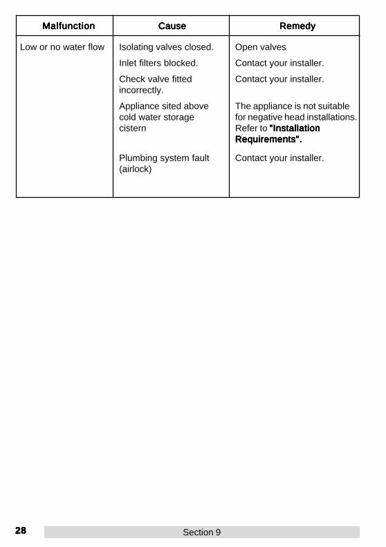
Low or no water flow Isolating valves closed. Open valves
Contact your installer.Inlet filters blocked.
Contact your installer.Check valve fittedincorrectly.
The appliance is not suitablefor negative head installations.Refer to "Installation"Installation"Installation"Installation"InstallationRequirements".Requirements".Requirements".Requirements".Requirements".
Appliance sited abovecold water storagecistern
MalfunctionMalfunctionMalfunctionMalfunctionMalfunction CauseCauseCauseCauseCause RemedyRemedyRemedyRemedyRemedy
Contact your installer.Plumbing system fault(airlock)

2929292929
2.2.2.2.2. F F F F Fault Diagnosis - Installer Maintenanceault Diagnosis - Installer Maintenanceault Diagnosis - Installer Maintenanceault Diagnosis - Installer Maintenanceault Diagnosis - Installer Maintenance
The Mira Event is one part of an entire plumbing system. The fitting of a pumpplaces additional requirements on the plumbing system. Some systems may requireplumbing modifications to allow them to cope with higher flow rates.
Providing the Mira Event has been correctly installed and is operated as advised,difficulties should not arise. Fault diagnosis and maintenance must be carried out bya competent person for whom the fault diagnosis table is provided.
In the event of any of the following tests failing, re-check as appropriate beforecontacting the Caradon Mira Customer Support Department (Refer to Back Cover).
Shower runs for ashort time (30-60seconds) then flowreduces, splutters orstops. Aggravatedwhen other hot tapsare in use. Lessevident on full cold.
Air is being sucked downthe vent pipe, as the hottake off to the shower istoo high up the pipe.
Refer to plumbing systemdiagrams in the section"Installation NotesInstallation NotesInstallation NotesInstallation NotesInstallation Notes" forcorrect connection method.Note the 1 metre hot take-offdimension. Considerincreasing cold feed pipe tocylinder to 28mm diameter.
MalfunctionMalfunctionMalfunctionMalfunctionMalfunction CauseCauseCauseCauseCause RemedyRemedyRemedyRemedyRemedy
Shower runs coolafter a short time (1-2 minutes) then flowsplutters.
Air ingress into hotpipework.
Refer to plumbing systemdiagrams in the section"Installation NotesInstallation NotesInstallation NotesInstallation NotesInstallation Notes" forcorrect connection method.
Flow of watervirtually stops andsurges on/off, after afew minutes.
Insufficient storage ofcold water in cistern.BS6700 recommends230 litres.
Increase storage of coldcistern.
Shower runs coldafter 5-10 minutes.
Insufficient storage of hotwater in cylinder.
Increase storage of hot water.
Shower temperatureaffected by use ofadjacent hot/coldtap.
Insufficiently sizedpipework for bothsystems to be usedtogether.
Increase pipe sizes orseparately feed shower.Refer to plumbing systemdiagrams in the section"Installation NotesInstallation NotesInstallation NotesInstallation NotesInstallation Notes".
Section 9

3030303030 Section 9
MalfunctionMalfunctionMalfunctionMalfunctionMalfunction CauseCauseCauseCauseCause RemedyRemedyRemedyRemedyRemedy
Shower temperaturetoo cold.
Hot water cylindertemperature less than120C above showertemperature.
Adjust cylinder temperature.
(Recommended not toexceed 600C BS6700)
Maximum showertemperature too hot.
Incorrect setting ofmaximum temperature.
Reset maximum temperature.Refer to “Commissioning:“Commissioning:“Commissioning:“Commissioning:“Commissioning:Adjustable MaximumAdjustable MaximumAdjustable MaximumAdjustable MaximumAdjustable MaximumTemperature Setting”.Temperature Setting”.Temperature Setting”.Temperature Setting”.Temperature Setting”.
Blend temperatureunstable
Spray plate blocked. Clean spray plate. Refer tothe Installation, Operationand Maintenance guidesupplied with the showerfittings.
Inlet filter blocked. Contact your installer.
Isolating valve partiallyclosed.
Open valve.
Maximum temperatureincorrectly set.
Reset maximum temperature.Refer to "Commissioning:"Commissioning:"Commissioning:"Commissioning:"Commissioning:Adjustable MaximumAdjustable MaximumAdjustable MaximumAdjustable MaximumAdjustable MaximumTemperature Setting"Temperature Setting"Temperature Setting"Temperature Setting"Temperature Setting"
Drip from showerhead.
Flow control gearpositioned incorrectly.Defective flow control.
Contact Caradon MiraService Office.
Renew Mixer Assembly.
Pump does notoperate.
Electrical supply failure. Check power supply.
On/off micro-switchfailure.
Renew.
PCB failure Renew.
Potentiometer defective. Replace PCB andPotentiometer

3131313131Section 9
MalfunctionMalfunctionMalfunctionMalfunctionMalfunction CauseCauseCauseCauseCause RemedyRemedyRemedyRemedyRemedy
Pump does notoperate.
Motor overheated,thermal switch operated.
Allow motor to cool beforefurther operation. (Refer to"Specifications: Continuous"Specifications: Continuous"Specifications: Continuous"Specifications: Continuous"Specifications: Continuousduty cycle"duty cycle"duty cycle"duty cycle"duty cycle").
Pump speed doesnot increase whenflow knob turnedpast indent.
Potentiometer gearincorrectly alighed ordisengaged.
Refer to "Maintenance:"Maintenance:"Maintenance:"Maintenance:"Maintenance:Mixer Assembly Renewal"Mixer Assembly Renewal"Mixer Assembly Renewal"Mixer Assembly Renewal"Mixer Assembly Renewal".
Low or no water Isolating valves closed. Open valves
Clean filters.Inlet filters blocked.
Refer to "Maintenance:"Maintenance:"Maintenance:"Maintenance:"Maintenance:Check Valve Renewal"Check Valve Renewal"Check Valve Renewal"Check Valve Renewal"Check Valve Renewal".
Check valve fittedincorrectly.
The appliance is not suitablefor negative head installations.Refer to "Installation"Installation"Installation"Installation"InstallationRequirements".Requirements".Requirements".Requirements".Requirements".
Appliance sited abovecold water storagecistern
Re-route the pipework toavoid airlock.
Plumbing system fault(airlock)
Clean spray plate. Refer tothe Installation, Operation andMaintenance guide suppliedwith the shower fittingsshower fittingsshower fittingsshower fittingsshower fittings.
Blocked spray plate.
Pump does not stop. Micro-switch defective. Renew.
Renew.PCB failure.

3232323232 Section 10
1. General1. General1. General1. General1. General
Each Mira Event is precision engineered to provide satisfactory performance providedit is installed and operated in accordance with our recommendations contained insection entitled “Installation Notes”“Installation Notes”“Installation Notes”“Installation Notes”“Installation Notes”.
2. Cleaning2. Cleaning2. Cleaning2. Cleaning2. Cleaning
Many household cleaners contain abrasives and chemical substances, and shouldnot be used for cleaning plated or plastic fittings. These finishes should be cleanedwith a mild washing up detergent or soap solution, and then wiped dry using a softcloth.
3.3.3.3.3. Inlet Filters Inlet Filters Inlet Filters Inlet Filters Inlet Filters, Cleaning or , Cleaning or , Cleaning or , Cleaning or , Cleaning or ‘O’‘O’‘O’‘O’‘O’ Seals Rene Seals Rene Seals Rene Seals Rene Seals Renewwwwwalalalalal
The following procedure can be applied for cleaning or renewing the inlet filters or inletfilter ‘O’ seals.
Warning!Warning!Warning!Warning!Warning!Isolate the electrical and water supply to the appliance before proceeding.Turn flow control on and off to relieve water pressure.
3.1.3.1.3.1.3.1.3.1. Use the push-fit release tool tolever off the temperature knob,temperature trim and flow knob.Unscrew the cover retaining screwand remove the cover by pullingthe bottom of the cover in anoutward and upward direction.
Inlet filter cap
Flow knob
Coverretainingscrew
Temperaturetrim
Temperatureknob
3.2.3.2.3.2.3.2.3.2. Remove the inlet filter capretaining screw and filter cap.
Section
10 MaintenanceMaintenanceMaintenanceMaintenanceMaintenance
3333333333
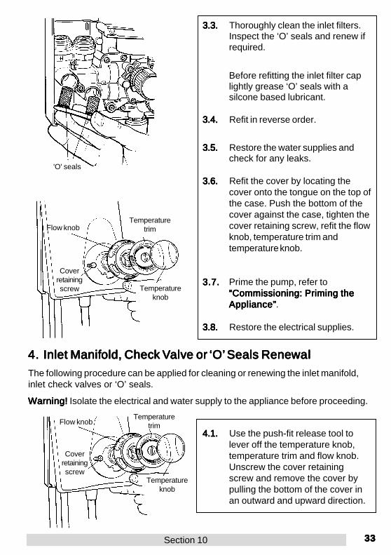
3.3.3.3.3.3.3.3.3.3. Thoroughly clean the inlet filters.Inspect the ‘O’ seals and renew ifrequired.
Section 10
4.1.4.1.4.1.4.1.4.1. Use the push-fit release tool tolever off the temperature knob,temperature trim and flow knob.Unscrew the cover retainingscrew and remove the cover bypulling the bottom of the cover inan outward and upward direction.
4.4.4.4.4. Inlet Manif Inlet Manif Inlet Manif Inlet Manif Inlet Manifold, Checold, Checold, Checold, Checold, Check k k k k VVVVValvalvalvalvalve or e or e or e or e or ‘O’‘O’‘O’‘O’‘O’ Seals Rene Seals Rene Seals Rene Seals Rene Seals Renewwwwwalalalalal
The following procedure can be applied for cleaning or renewing the inlet manifold,inlet check valves or ‘O’ seals.
Warning!Warning!Warning!Warning!Warning! Isolate the electrical and water supply to the appliance before proceeding.
3.8.3.8.3.8.3.8.3.8. Restore the electrical supplies.
3.7.3.7.3.7.3.7.3.7. Prime the pump, refer to“Commissioning: Priming the“Commissioning: Priming the“Commissioning: Priming the“Commissioning: Priming the“Commissioning: Priming theAppliance”Appliance”Appliance”Appliance”Appliance”.
3.6.3.6.3.6.3.6.3.6. Refit the cover by locating thecover onto the tongue on the top ofthe case. Push the bottom of thecover against the case, tighten thecover retaining screw, refit the flowknob, temperature trim andtemperature knob.
3.5.3.5.3.5.3.5.3.5. Restore the water supplies andcheck for any leaks.
3.4.3.4.3.4.3.4.3.4. Refit in reverse order.
Before refitting the inlet filter caplightly grease ‘O’ seals with asilcone based lubricant.
'O' seals
Flow knobTemperature
trim
Coverretainingscrew Temperature
knob
Flow knobTemperature
trim
Coverretainingscrew
Temperatureknob

3434343434 Section 10
4.2.4.2.4.2.4.2.4.2. Disconnect the electrical supplycable from the terminal block andearth stud.Remove the flexible hose fromthe appliance.
4.7.4.7.4.7.4.7.4.7. Remove the inlet manifold, mixerassembly, pump saddle clampand on/off micro-switch retainingscrews. Remove the drip shieldthe micro-switch and the pumpsaddle clamp.
4.6.4.6.4.6.4.6.4.6. Using the push-fit release tool,push back and hold the colletsfrom the supply pipework, lift theappliance from the wall toremove the supply pipework fromthe inlet manifold.
4.5.4.5.4.5.4.5.4.5. Remove the three wall fixingscrews,
4.4.4.4.4.4.4.4.4.4. Remove the flexible hose fromthe appliance.
4.34.34.34.34.3. Disconnect the electrical supplycable from the terminal block andearth stud.
Release tool
Collets
Removescrews 1 to 12

3535353535Section 10
4.8.4.8.4.8.4.8.4.8. Whilst gripping the mixerassembly disconnect the inletmanifold.
4.15.4.15.4.15.4.15.4.15. Restore the electrical supplies.
4.14.4.14.4.14.4.14.4.14. Prime the pump, refer to“Commissioning: Priming the“Commissioning: Priming the“Commissioning: Priming the“Commissioning: Priming the“Commissioning: Priming theAppliance”Appliance”Appliance”Appliance”Appliance”.
4.13.4.13.4.13.4.13.4.13. Refit the cover by locating thecover onto the tongue on the topof the case. Push the bottom ofthe cover against the case,tighten the cover retaining screw,refit the flow knob, temperaturetrim and temperature knob.
4.12.4.12.4.12.4.12.4.12. Restore the water supplies andcheck for any leaks.
4.11.4.11.4.11.4.11.4.11. Refit in reverse order.
4.10.4.10.4.10.4.10.4.10. Inspect inlet manifold ‘O’ sealsand renew if required.
Tip!Tip!Tip!Tip!Tip! When refitting the inletmanifold, lightly grease ‘O’ sealswith a silicone based lubricant.
4.9.4.9.4.9.4.9.4.9. The ports adjacent to the mixerassembly contain the inlet checkvalves. The check valves can beremoved and replaced ifrequired. Ensure the check valveis inserted so the ‘O’ seal oncheck valve faces into the outletof the manifold.
Hose washer
Flexible hose
Flow knob Temperaturetrim
Coverretainingscrew Temperature
knob
Inletmanifold Mixer
assembly

3636363636 Section 10
5.5.5.5.5. Push-fit Collet or Push-fit Collet or Push-fit Collet or Push-fit Collet or Push-fit Collet or ‘O’‘O’‘O’‘O’‘O’ Seals Rene Seals Rene Seals Rene Seals Rene Seals Renewwwwwalalalalal
The following procedure can be applied for renewing the push-fit collets or inletmanifold internal ‘O’ seals.
Warning!Warning!Warning!Warning!Warning! Isolate the electrical and water supply to the appliance before proceeding.
5.1.5.1.5.1.5.1.5.1. Follow the instructions 4.14.14.14.14.1 to 4.44.44.44.44.4contained in the section “Inlet“Inlet“Inlet“Inlet“InletManifold, Check Valve or ‘O’Manifold, Check Valve or ‘O’Manifold, Check Valve or ‘O’Manifold, Check Valve or ‘O’Manifold, Check Valve or ‘O’Seals Renewal”.Seals Renewal”.Seals Renewal”.Seals Renewal”.Seals Renewal”.
5.4.5.4.5.4.5.4.5.4. Follow the instructions 4.94.94.94.94.9 to 4.134.134.134.134.13contained in the section “Inlet“Inlet“Inlet“Inlet“InletManifold, Check Valve or ‘O’Manifold, Check Valve or ‘O’Manifold, Check Valve or ‘O’Manifold, Check Valve or ‘O’Manifold, Check Valve or ‘O’Seals Renewal”Seals Renewal”Seals Renewal”Seals Renewal”Seals Renewal”.
5.3.5.3.5.3.5.3.5.3. Inspect the internal ‘O’ seals forsigns of damage and renew ifrequired.
5.2.5.2.5.2.5.2.5.2. For top or back inlet suppliesFor top or back inlet suppliesFor top or back inlet suppliesFor top or back inlet suppliesFor top or back inlet supplies
Using the push-fit release toollever out the collets. Renew thecollets if required.
For bottom inlet suppliesFor bottom inlet suppliesFor bottom inlet suppliesFor bottom inlet suppliesFor bottom inlet suppliesFollow the instructions 4.5 4.5 4.5 4.5 4.5 to 4.64.64.64.64.6contained in the section “Inlet“Inlet“Inlet“Inlet“InletManifold, Check Valve or ‘O’Manifold, Check Valve or ‘O’Manifold, Check Valve or ‘O’Manifold, Check Valve or ‘O’Manifold, Check Valve or ‘O’Seals Renewal”.Seals Renewal”.Seals Renewal”.Seals Renewal”.Seals Renewal”.
Using the push-fit release toollever out the collets. Renew thecollets if required.
Warning!Warning!Warning!Warning!Warning!
Do notDo notDo notDo notDo not insert fingers into thecollets as this can result in injury.
Collets
Releasetool

3737373737Section 10
6. Mixer Assembly Renewal6. Mixer Assembly Renewal6. Mixer Assembly Renewal6. Mixer Assembly Renewal6. Mixer Assembly Renewal
The following procedure can be applied for cleaning or replacing the mixer assembly.
Warning!Warning!Warning!Warning!Warning! Isolate the electrical and water supply to the appliance before proceeding.
6.1.6.1.6.1.6.1.6.1. Follow the instructions 4.14.14.14.14.1 to 4.44.44.44.44.4contained in the section “Inlet“Inlet“Inlet“Inlet“InletManifold Renewal”Manifold Renewal”Manifold Renewal”Manifold Renewal”Manifold Renewal”.
6.4.6.4.6.4.6.4.6.4. Remove micro-switch retainingscrews, drip shield and micro-switch.
Do not remove PCB wiring frommicro-switch.
6.3.6.3.6.3.6.3.6.3. Remove the gear pot securingscrew and gear pot from mixerassembly.
6.2.6.2.6.2.6.2.6.2. Remove the inlet manifold andmixer assembly retaining screws,pump saddle clamp retainingscrews and clamp.
Remove screws 1 to 10
Remove screws 11 to 13

3838383838
6.5.6.5.6.5.6.5.6.5. Separate the mixer assembly fromthe inlet manifold and the pumpassembly.
6.10.6.10.6.10.6.10.6.10. Restore the electrical supplies.
6.9.6.9.6.9.6.9.6.9. Prime the pump, refer to“Commissioning: Priming the“Commissioning: Priming the“Commissioning: Priming the“Commissioning: Priming the“Commissioning: Priming theAppliance”Appliance”Appliance”Appliance”Appliance”.
6.8.6.8.6.8.6.8.6.8. Refit the cover by locating thecover onto the tongue on the topof the case. Push the bottom ofthe cover against the case,tighten the cover retaining screw,refit the flow knob, temperaturetrim and temperature knob.
6.7.6.7.6.7.6.7.6.7. Restore the water supplies andcheck for any leaks.
6.6.6.6.6.6.6.6.6.6. Refit in reverse order.
Note!Note!Note!Note!Note! Ensure that the ‘O’ sealsbetween the mixer assembly andthe pump assembly are correctlyseated on eacheacheacheacheach male spigot.
Tip!Tip!Tip!Tip!Tip! When refitting the mixerassembly lightly grease ‘O’ sealswith a silicone based lubricant.
Note!Note!Note!Note!Note! When refitting the gearpot care should be taken to alignthe raised marking on gear withthe adjacent marking on the flowcontrol knob gear.
Mixer assembly
'O' seals
Inletmanifold
Raised markings
Potentiometergear
Flow controlknob gear
Raisedmarkings
Flow knobTemperature
trim
Coverretainingscrew Temperature
knob
Section 10

3939393939
7.7.7.7.7. Pump Assemb Pump Assemb Pump Assemb Pump Assemb Pump Assembly Renely Renely Renely Renely Renewwwwwalalalalal
The following procedure can be applied for cleaning or replacing the pump assembly.
Warning!Warning!Warning!Warning!Warning! Isolate the electrical and water supply to the appliance before proceeding.
7.1.7.1.7.1.7.1.7.1. Use the push-fit release tool tolever off the temperature knob,temperature trim and flow knob.Unscrew the cover retainingscrew and remove the cover bypulling the bottom of the cover inan outward and upward direction.
7.3.7.3.7.3.7.3.7.3. Remove saddle clamp retainingscrews and clamp.
7.2.7.2.7.2.7.2.7.2. Disconnect the pump electricalsupply wiring from the pumpassembly and the earth wire fromthe earth stud on the pcb.
Section 10
Flow knob Temperaturetrim
Coverretainingscrew
Temperatureknob

4040404040
7.4.7.4.7.4.7.4.7.4. Separate pump assembly frommixer assembly.
7.9.7.9.7.9.7.9.7.9. Restore the electrical supplies.
7.8.7.8.7.8.7.8.7.8. Prime the pump, refer to“Commissioning: Priming the“Commissioning: Priming the“Commissioning: Priming the“Commissioning: Priming the“Commissioning: Priming theAppliance”Appliance”Appliance”Appliance”Appliance”.
7.7.7.7.7.7.7.7.7.7. Refit the cover by locating thecover onto the tongue on the topof the case. Push the bottom ofthe cover against the case,tighten the cover retaining screw,refit the flow knob, temperaturetrim and temperature knob.
7.67.67.67.67.6. Restore the water supplies andcheck for any leaks.
7.5.7.5.7.5.7.5.7.5. Refit in reverse order.
Note!Note!Note!Note!Note! Ensure that the ‘O’ sealsbetween the mixer assembly andthe pump assembly are correctlyseated on eacheacheacheacheach male spigot.
Tip!Tip!Tip!Tip!Tip! When refitting the pumpassembly lightly grease ‘O’ sealswith a silicone based lubricant.
Mixer assembly
'O' seals
Pumpassembly
Flow knobTemperature
trim
Coverretainingscrew Temperature
knob
Section 10

4141414141
8.8.8.8.8. PCB and P PCB and P PCB and P PCB and P PCB and Potentiometer Reneotentiometer Reneotentiometer Reneotentiometer Reneotentiometer Renewwwwwalalalalal
Warning!Warning!Warning!Warning!Warning! Isolate the electrical and water supply to the appliance before proceeding.
Disconnect wiring by pulling on body of spade connector only and not the wire itself.
CAUTION! CAUTION! CAUTION! CAUTION! CAUTION! Before proceeding with any electrical work on this unit ensure that thecapacitors on the printed circuit board are fully discharged. To do this, turn the flowcontrol knob fully 'ON' and 'OFF' again after the power has been isolated from theunit.
8.1.8.1.8.1.8.1.8.1. Use the push-fit release tool tolever off the temperature knob,temperature trim and flow knob.Unscrew the cover retainingscrew and remove the cover bypulling the bottom of the cover inan outward and upward direction.
8.3.8.3.8.3.8.3.8.3. Remove the PCB securing screwand disconnect the PCB supplywires from on/off micro-switch.
8.2.8.2.8.2.8.2.8.2. Disconnect the electrical supplycable from the appliance terminalblock.
Section 10
Flow knob Temperaturetrim
Coverretainingscrew Temperature
knob

4242424242
8.4.8.4.8.4.8.4.8.4. Disconnect and remove the oldPCB.
8.10.8.10.8.10.8.10.8.10. Ensure all wires are neatly tuckedinto the case V channels aroundthe motor & mixer assembly.
8.9.8.9.8.9.8.9.8.9. Position and secure the PCB andreconnect the Earth wire.
8.8.8.8.8.8.8.8.8.8. There is no change to theconnection of the orange wires tothe potentiometer.
8.7.8.7.8.7.8.7.8.7. Fit one end of the black wire thatis supplied loose to the free frontmotor terminal and the other endto the free on/off micro-switchterminal.
8.6.8.6.8.6.8.6.8.6. Fit the longer black wire of thenew PCB to one of the on/offmicro-switch terminals.
8.5.8.5.8.5.8.5.8.5. Fit the shorter black wire of thenew PCB to the free rear motorterminal.
PCB
Orange Wires
GreenEarth Wire
Pump andMotor Assembly
Black Wire(supplied loose)
On/OffMicroswitch
Potentiometer
Long BlackWire
PCBEnsure wires areneatly tuckedinto V-Channels
EarthWire
Pump andMotor
Assembly
On/OffMicroswitch
Potentiometer
Section 10
NL

4343434343
8.11.8.11.8.11.8.11.8.11. Remove the gear potentiometersecuring screw and gearpotentiometer with drip shieldfrom mixer assembly.
Note! Note! Note! Note! Note! When refitting the gear potcare should be taken to align theraised marking on gear with theadjacent marking on the flowcontrol knob gear.
Restore the electrical supplies.
8.13.8.13.8.13.8.13.8.13. Refit the cover by locating thecover onto the tongue on the topof the case. Push the bottom ofthe cover against the case,tighten the cover retaining screw,refit the flow knob, temperaturetrim and temperature knob.
8.12.8.12.8.12.8.12.8.12. Refit in reverse order.
Section 10
Temperaturetrim
Coverretainingscrew Temperature
knob
Remove screw 13
Raised markings
Potentiometergear
Flow control knobgear
Raisedmarkings
Flow knob

4444444444
9.9.9.9.9. Micro-s Micro-s Micro-s Micro-s Micro-switchwitchwitchwitchwitch
Warning!Warning!Warning!Warning!Warning! Isolate the electrical and water supply to the appliance before proceeding.
Disconnect wiring by pulling on body of spade connector only and not the wire itself.
9.1.9.1.9.1.9.1.9.1. Remove micro-switch retainingscrews the drip shield and micro-switch. Remove electrical supplywiring to micro-switch.
9.4.9.4.9.4.9.4.9.4. Refit the acover by locating thecover onto the tongue on the topof the case. Push the bottom ofthe cover against the case,tighten the cover retaining screw,refit the flow knob, temperaturetrim and temperature knob.
9.3.9.3.9.3.9.3.9.3. Refit in reverse order.
9.2.9.2.9.2.9.2.9.2. Renew micro-switch.
Restore the electrical supplies.
Flow knobTemperature
trim
Coverretainingscrew Temperature
knob
Section 10

4545454545
WirWirWirWirWiring Diaging Diaging Diaging Diaging DiagrrrrramamamamamAppendix
1
Appendix 1
BLA
CK
BLA
CK
ORANGE
To Motor
ORANGE
Potentiometer

4646464646
DimensionsDimensionsDimensionsDimensionsDimensionsAppendix
2
Appendix 2
All dimensions are nominal and in millimetres.
278
172
21
28 66 58
90
128

4747474747
Appendix
3 Spare PartsSpare PartsSpare PartsSpare PartsSpare Parts
Spare PartsSpare PartsSpare PartsSpare PartsSpare Parts
Appendix 3

4848484848
1.1.1.1.1. Spare P Spare P Spare P Spare P Spare Parararararts Listts Listts Listts Listts List
Appendix 3
147 67 Check Valve Pack209 59 Push-fit Release Tool209 72 Filter Pack Spares209 73 Unit Screw Pack - components identified 'A'209 74 Fixing Screw Pack (not shown)209 75 Seal Pack, Mixer - components identified 'C'209 79 Manifold Assembly - components identified 'F'209 80 Switch Assembly - components identified 'D'211 38 Mixer Assembly211 60 Pump Assembly211 61 Speed Control Pack - components identified 'E'211 62 Push-fit Pack916 46 Knob Set920 93 Cover Assembly

4949494949
2.2.2.2.2. Spare P Spare P Spare P Spare P Spare Parararararts Diagts Diagts Diagts Diagts Diagrrrrramamamamam
Appendix 3
211 60
920 93
209 72
211 38
A
209 59, F
211 62
916 46
F
FF, A A
FF, A
A
E
DC
E
A
A
C
147 67

5050505050
Appendix
4 Optional AccessorOptional AccessorOptional AccessorOptional AccessorOptional Accessoriesiesiesiesies
Appendix 4
RF2 RF2 RF2 RF2 RF2 Fixed handset holder. A simple alternative or additional holder for a showerhandset, available as an optional accessory from your Mira stockist.
RF2 RF2 RF2 RF2 RF2 Fixed handset holder

5151515151
NotesNotesNotesNotesNotes

5252525252P3018/2 © Caradon Mira Limited, April 1998
Mira ShowersMira ShowersMira ShowersMira ShowersMira ShowersCaradon Plumbing LtdCromwell Road,Cheltenham GL52 5EP.
BS EN ISO 9001 : 1994Reg. No. FM 14648
Mira is a registered trade mark of subsidiariesof Caradon plc.The company reserves the right to alter productspecifications without notice.
Failing this, contact your installer to ensure that the product hasbeen installed and commissioned in full accord with our detailedinstallation instructions. Our Customer Services is available, onthe number shown below, to advise you or your installer.
If this does not resolve the difficulty, contact our CustomerServices who will give every assistance and, if appropriate,arrange for our local Service Engineer or Agent to call on amutually agreeable date.
If, through circumstances beyond our control, we are unable toprovide this cover we will, with prior agreement, authorise acompetent local installer to attend.
Within the Guarantee period there will be no charge for the partsor labour insofar as a fault with our product is concerned.However, it is important to appreciate that our Guaranteeextends to our product only and that it does not cover difficultiesarising from incorrect installation or misuse.
During a Service visit a responsible person – familiar with thepurpose of the visit – should be present. Should our ServiceEngineer or Agent be unable to gain access at the pre-arrangedtime a callout charge may be made.
Payment for Service visits, if applicable, should be madedirectly to the Service Engineer or Agent, using either Visa,Access or a cheque supported by a banker’s card.
To contact us:-To contact us:-To contact us:-To contact us:-To contact us:-For England, Wales and ScotlandFor England, Wales and ScotlandFor England, Wales and ScotlandFor England, Wales and ScotlandFor England, Wales and ScotlandTelephone 01242 262888 (12 Direct Lines)Telephone 01242 262888 (12 Direct Lines)Telephone 01242 262888 (12 Direct Lines)Telephone 01242 262888 (12 Direct Lines)Telephone 01242 262888 (12 Direct Lines)and ask for Caradon Plumbing Solutions Customerand ask for Caradon Plumbing Solutions Customerand ask for Caradon Plumbing Solutions Customerand ask for Caradon Plumbing Solutions Customerand ask for Caradon Plumbing Solutions CustomerServicesServicesServicesServicesServices• For advice on product maintenance• To order spare parts• To arrange a service visit• For product advice and problem solving• To order Installation, Operation and Maintenance Guides• For your feedback on our products or servicesBy Fax: (01242) 282595By Post: Caradon Plumbing Solutions, Cromwell Road
Cheltenham, Gloucestershire, GL52 5EP.
For Northern IrelandFor Northern IrelandFor Northern IrelandFor Northern IrelandFor Northern IrelandBy Phone: 01232 401909 – Monday to Friday 9am–5pmBy Fax: 01232 401235 – 24 HoursBy Post: Wm. H. Leech & Son Ltd, Unit 3,
34, Montgomery Road, Belfast, BT6 9HL.
For EireFor EireFor EireFor EireFor EireBy Phone: Dublin 01 4591344 – Monday to Friday 9am–5pmBy Fax: Dublin 01 4592329 – 24 HoursBy Post: Modern Plant Ltd, Otter House, Naas Road,
Clondalkin, Dublin 22, Eire.
GuaranteeGuaranteeGuaranteeGuaranteeGuaranteeCaradon Plumbing Solutions guarantee this productagainst any defect of materials or workmanship for twoyears from the date of purchase, provided that the producthas been installed correctly and used and maintained inaccordance with the instructions supplied.
Any part found to be defective during the guarantee periodwill be replaced or repaired – at our option – withoutcharge, provided that the product has been properly usedand maintained.
The product should not be taken apart, modified orrepaired except by a person authorised by Caradon PlumbingSolutions.
Your statutory rights are in no way affected by thisguarantee.
After Sales Service – how we canAfter Sales Service – how we canAfter Sales Service – how we canAfter Sales Service – how we canAfter Sales Service – how we canhelp youhelp youhelp youhelp youhelp youCaradon Plumbing Solutions have a team of expert staffready to provide assistance, should you experience anydifficulty with your Mira shower.
The Caradon Plumbing Solutions Customer Services isavailable to give you advice on any problem encountered.Should the problem be unable to be resolved by advice,we will offer either a replacement part to be sent to you,or for one of our Service Engineers or Agents to call.
Spare PartsSpare PartsSpare PartsSpare PartsSpare PartsAt Caradon Plumbing Solutions we keep a stock of allfunctional parts of our products for up to ten years fromthe date of final manufacture of the product.
If during that period, our stock of a particular part isexhausted we will, as an alternative, provide an equivalentnew product or part at a price equating to the cost of repairto the old, bearing in mind the age of the product.
Caradon Plumbing Solutions will normally despatch spareparts within two working days and by 1st class post. In theinterests of customer safety, spares that require exposureto areas of mains voltage can only be sent to a competentperson.
Payment for such parts – if applicable – can be made byVisa or Access over the phone at the time of ordering.Should payment by cheque be preferred a pro formainvoice will be sent.
Customer Care PolicyCustomer Care PolicyCustomer Care PolicyCustomer Care PolicyCustomer Care PolicyIf within a short time of installation the product does notfunction correctly, first check with the Installation, Operationand Maintenance Guide to see if the difficulty can be overcomeby simple home maintenance.
www.mira-showers.co.ukwww.mira-showers.co.ukwww.mira-showers.co.ukwww.mira-showers.co.ukwww.mira-showers.co.uk
Section Customer SerCustomer SerCustomer SerCustomer SerCustomer Servicevicevicevicevice