thermozone ag 4500/5000 a/w - sefen
TRANSCRIPT

Thermozone AG 4500/5000 A/W
.... 22GB .... 19SE

2
Thermozone AG 4500/5000 A/W
Connections
Type L [mm]
AG4515A 1500AG4520A 2000AG5010A 1000AG5015A 1500AG5020A 2000AG4515WL/WH 1500AG4520WL/WH 2000AG4525WL/WH 2000AG5010WL/WH 1000AG5015WL/WH 1500AG5020WL/WH 2000AG5025WL/WH 2500
Minimum distance
770
35
500
450
L/2
4040
20750L
110
38145
50
75
320
35
60
min 200
min
80
Type Connection
AG4515WH DN20AG5015WH DN20AG4515WL DN25AG4520WH DN25AG5010WL DN25AG5015WL DN25AG5010WH DN25AG5020WH DN25AG4520WL DN32AG4525WH/WL DN32AG5020WL DN32AG5025WH/WL DN32
3
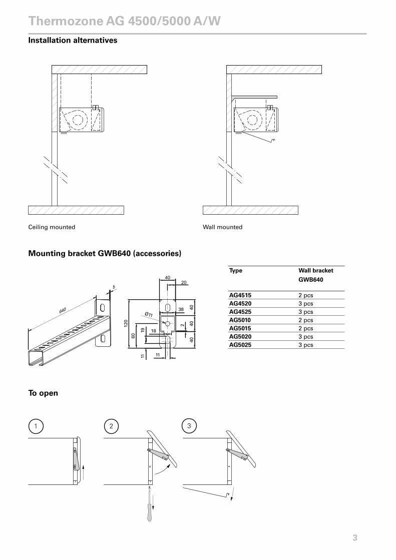
Thermozone AG 4500/5000 A/WInstallation alternatives
Wall mountedCeiling mounted
40
640
5
Ø11
20
38
18
11
120
60
1911
2
4040
40
Mounting bracket GWB640 (accessories)
To open
1 2 3
Type Wall bracket
GWB640
AG4515 2 pcsAG4520 3 pcsAG4525 3 pcsAG5010 2 pcsAG5015 2 pcsAG5020 3 pcsAG5025 3 pcs

SD20
AV20/25
TRV20/25
BPV10
TVV20/25
JVF20/25
VR20/25
Water regulators
230V ~230V ~
C̊ C̊
AV20/25
JVF20/25
TRV20/25
BPV10
SD20
RTE/KRT
TVV20/25
SD20
RTE/KRT
VR
20/2
5
4
Thermozone AG 4500/5000 A/W
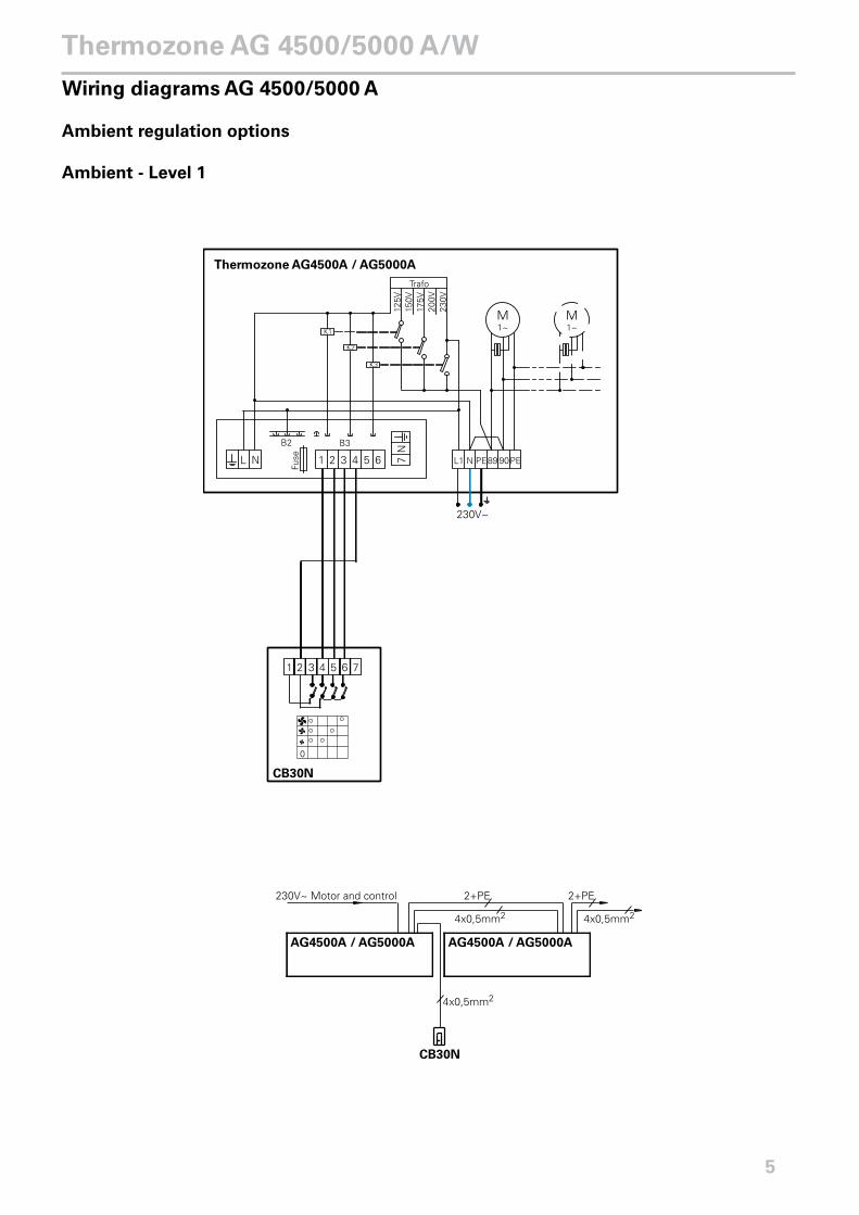
Wiring diagrams AG 4500/5000 A
Ambient regulation options
Ambient - Level 1
5
Thermozone AG 4500/5000 A/W

Ambient - Level 2
6
Thermozone AG 4500/5000 A/W

Wiring diagrams AG 4500/5000 W
Water regulation options
Water - Level 1
7
Thermozone AG 4500/5000 A/W

Water - Level 2
0
C˚
230V~
2 3 4 5 6 712 3 4 5 6 7 N L1
SD20
TVV20/25
CB30N
Hi Lo
RTI2
MDC
LN DC DC 1211 14 2221 24
Doorcontact
230V~ Motor and control
AG4500W / AG5000W
CB30N
4x0,5mm2
4x0,5mm2 4x0,5mm2
2+PE
AG4500W / AG5000W
2+PE
MDCIOA 1
3x0,5mm2
2x0,5mm2
2+PE2+PE2x0,5mm22+PE
RTI2SD20
150V
125V
175V
200V
230V
Trafo
K3
K2
K1
L N 1 2 3 4 5Fu
se 6 L1 N PE89 90PE7N
230V~
Thermozone AG4500W / AG5000W
M1~
M1~
8
Thermozone AG 4500/5000 A/W

Water - Level 3
SD20
TVV20/25
ADEAEB
ADEAR
ADEAGD
1
2
L N 4 5 8 9 20 21 31 41 5011 51 8180 8382 84 8685 87 G2G1 G4G3 G530 406
64 5 87 9 1110
230V~
ADEAOS
4MDCDC
ADEAIS
230V~ Motor and control
AG4500W / AG5000W
ADEAEB +ADEAGD
5x0,5mm2
5x0,5mm2 5x0,5mm2
2+PE
AG4500W / AG5000W
2+PE
ADEAR
ADEAIS SD20
ADEAOS
MDCDC
8x0,5mm2
2+PE
2x0,5mm2
2x0,5mm2
2x0,5mm2
2+PE
150V
125V
175V
200V
230V
Trafo
K3
K2
K1
L N 1 2 3 4 5
Fuse 6 L1 N PE89 90PE7
N
230V~
Thermozone AG4500W / AG5000W
M1~
M1~
9
Thermozone AG 4500/5000 A/W

Incoming / outgoing water temperature 130/70°CAir temp. in = +10°C Air temp. in = +15°C Air temp. in = +20°C
Type Fan position
Airflow [m3/h]
Output [kW]
Air.temp. out [°C]
Water flow [l/s]
Output [kW]
Air.temp. out. [°C]
Water flow [l/s]
Output [kW]
Air.temp. out [oC]
Water flow [l/s]
AG4515WH high 4800 49,7 40,8 0,21 46,6 43,9 0,19 43,5 46,9 0,18low 2400 32,6 50,4 0,14 30,6 52,9 0,13 28,6 55,4 0,12
AG4520WH high 7000 81,8 44,7 0,34 76,3 47,4 0,32 71,1 50,2 0,29low 3500 53,3 55,3 0,22 49,8 57,2 0,21 46,4 59,4 0,19
AG4525WH high 9400 107,1 43,8 0,44 100,2 46,7 0,41 93,3 49,5 0,39low 4700 70,0 54,3 0,29 65,6 56,6 0,27 61,2 57,1 0,25
AG5010WH high 4200 49,7 45,2 0,21 46,4 47,8 0,19 43,1 50,5 0,18low 2100 32,7 56,3 0,14 30,5 58,1 0,13 28,3 60,1 0,15
AG5015WH high 6500 59,0 37,0 0,24 55,3 40,3 0,23 51,6 43,6 0,21low 3250 39,4 46,0 0,16 37,0 48,8 0,15 34,5 51,5 0,14
AG5020WH high 8500 91,3 41,9 0,38 85,5 44,9 0,35 79,6 47,8 0,33low 4250 60,3 52,1 0,25 56,5 54,5 0,23 52,7 56,8 0,22
AG5025WH high 10600 114,9 42,2 0,48 107,5 45,1 0,44 100,1 48,1 0,41low 5300 75,7 52,4 0,31 70,9 54,8 0,29 66,1 57,1 0,27
Incoming / outgoing water temperature 110/80°CAir temp. in = +10°C Air temp. in = +15°C Air temp. in = +20°C
Type Fan position
Airflow [m3/h]
Output [kW]
Air.temp. out [°C]
Water flow [l/s]
Output [kW]
Air.temp. out. [°C]
Water flow [l/s]
Output [kW]
Air.temp. out [oC]
Water flow [l/s]
AG4515WH high 4800 50,3 41,1 0,41 47,3 44,3 0,39 44,2 47,4 0,36low 2400 32,7 50,5 0,27 30,8 53,1 0,25 28,8 55,7 0,24
AG4520WH high 7000 83,4 45,5 0,69 78,3 48,2 0,64 73,2 51,1 0,60low 3500 53,7 55,6 0,44 50,5 57,8 0,42 47,2 60,1 0,39
AG4525WH high 9400 109,8 44,7 0,91 103,1 47,6 0,85 96,4 50,5 0,79low 4700 71,0 54,9 0,59 66,7 57,2 0,55 62,4 59,4 0,51
AG5010WH high 4200 51,9 46,7 0,43 48,7 49,4 0,40 45,4 52,1 0,38low 2100 33,6 57,6 0,28 31,4 59,5 0,26 29,4 61,5 0,24
AG5015WH high 6500 59,8 37,4 0,49 56,2 40,7 0,46 52,6 44,0 0,43low 3250 39,7 46,3 0,33 37,3 49,1 0,31 34,9 51,9 0,29
AG5020WH high 8500 93,3 42,6 0,77 87,6 45,6 0,72 81,8 48,6 0,68low 4250 61,0 52,6 0,50 57,3 55,0 0,47 53,6 57,4 0,44
AG5025WH high 10600 117,6 42,9 0,97 110,4 45,9 0,91 103,1 48,9 0,85low 5300 76,7 53,0 0,63 72,0 55,4 0,59 67,3 57,7 0,56
Incoming / outgoing water temperature 90/70°CAir temp. in = +10°C Air temp. in = +15°C Air temp. in = +20°C
Type Fan position
Airflow [m3/h]
Output [kW]
Air.temp. out [°C]
Water flow [l/s]
Output [kW]
Air.temp. out. [°C]
Water flow [l/s]
Output [kW]
Air.temp. out [oC]
Water flow [l/s]
AG4515WH high 4800 41,7 35,8 0,51 38,7 38,9 0,48 35,6 42,1 0,44low 2400 27,1 43,5 0,33 25,1 46,1 0,31 23,2 48,7 0,28
AG4520WH high 7000 69,2 39,4 0,85 64,1 42,2 0,79 59,0 45,0 0,73low 3500 44,7 47,9 0,55 41,2 50,0 0,51 30,0 52,2 0,47
AG4525WH high 9400 91,2 38,8 1,12 84,5 41,7 1,04 77,7 44,6 0,96low 4700 58,8 47,2 0,72 54,5 49,5 0,67 50,2 51,7 0,62
AG5010WH high 4200 43,3 40,6 0,53 40,0 43,3 0,49 36,7 46,0 0,45low 2100 28,0 49,5 0,34 25,8 51,5 0,32 23,7 53,6 0,29
AG5015WH high 6500 49,7 32,7 0,61 46,1 36,1 0,57 42,4 39,4 0,52low 3250 32,9 40,1 0,40 30,5 42,9 0,38 28,1 45,7 0,34
AG5020WH high 8500 77,8 37,2 0,96 71,1 40,1 0,88 66,1 43,1 0,81low 4250 50,7 45,5 0,62 47,0 47,9 0,58 43,3 50,3 0,53
AG5025WH high 10600 98,1 37,5 1,21 90,9 40,5 1,12 83,2 43,3 1,02low 5300 63,8 45,8 0,78 59,1 48,2 0,73 54,5 50,5 0,67
Output charts water
10
Thermozone AG 4500/5000 A/W

Incoming / outgoing water temperature 82/71°CAir temp. in = +15°C Air temp. in = +20°C
Type Fan position
Airflow [m3/h]
Output [kW]
Air.temp. out. [°C]
Water flow [l/s]
Output [kW]
Air.temp. out [oC]
Water flow [l/s]
AG4515WH high 4800 37,6 38,3 0,84 34,5 41,4 0,77low 2400 24,3 45,1 0,54 22,3 47,7 0,50
AG4520WH high 7000 62,5 41,5 1,39 57,4 44,4 1,28low 3500 39,7 48,7 0,89 36,5 51,0 0,81
AG4525WH high 9400 82,5 41,1 1,84 75,4 43,8 1,68low 4700 53,0 48,5 1,18 48,6 50,7 1,08
AG5010WH high 4200 39,3 42,8 0,88 36,1 45,5 0,80low 2100 25,0 50,4 0,56 23,0 52,5 0,51
AG5015WH high 6500 44,8 35,5 1,00 41,1 38,8 0,92low 3250 29,6 42,0 0,66 27,2 44,8 0,61
AG5020WH high 8500 70,1 39,5 1,56 64,3 42,5 1,43low 4250 45,6 46,9 1,02 41,9 49,3 0,93
AG5025WH high 10600 88,3 39,8 1,97 81,1 42,7 1,81low 5300 57,4 47,1 1,28 52,7 49,5 1,18
Incoming / outgoing water temperature 80/60°CAir temp. in = +10°C Air temp. in = +15°C Air temp. in = +20°C
Type Fan position
Airflow [m3/h]
Output [kW]
Air.temp. out [°C]
Water flow [l/s]
Output [kW]
Air.temp. out. [°C]
Water flow [l/s]
Output [kW]
Air.temp. out [oC]
Water flow [l/s]
AG4515WH high 4800 35,3 31,8 0,43 32,2 35,0 0,39 29,2 38,1 0,36low 2400 23,0 38,4 0,28 21,0 41,0 0,26 19,0 43,5 0,23
AG4520WH high 7000 58,4 34,8 0,71 53,3 37,6 0,65 48,2 40,5 0,59low 3500 37,6 41,9 0,46 34,4 44,2 0,42 31,1 46,4 0,38
AG4525WH high 9400 77,0 34,3 0,94 70,3 37,2 0,86 63,2 40,0 0,77low 4700 49,8 41,5 0,61 45,4 43,7 0,56 41,1 46,0 0,50
AG5010WH high 4200 36,3 35,7 0,44 33,1 38,4 0,41 29,8 41,1 0,36low 2100 23,5 43,3 0,29 21,4 45,2 0,26 19,3 47,3 0,24
AG5015WH high 6500 42,0 29,2 0,51 38,4 32,5 0,47 34,7 35,9 0,43low 3250 27,9 35,5 0,34 25,5 38,3 0,31 23,0 41,1 0,28
AG5020WH high 8500 65,4 32,9 0,80 59,7 35,9 0,73 53,9 38,8 0,66low 4250 42,7 39,9 0,52 39,0 42,3 0,48 35,3 44,7 0,43
AG5025WH high 10600 82,4 33,1 1,01 75,2 36,1 0,92 67,9 39,0 0,83low 5300 49,1 42,5 0,60 49,1 42,5 0,60 44,3 44,9 0,54
11
Thermozone AG 4500/5000 A/W

Incoming / outgoing water temperature 70/40°CAir temp. in = +15°C Air temp. in = +20°C
Type Fan position
Airflow [m3/h]
Output [kW]
Air.temp. out. [°C]
Water flow [l/s]
Output [kW]
Air.temp. out [oC]
Water flow [l/s]
AG4515WL high 4800 44,8 43 0,55 40,5 45 0,49low 2400 27,9 50 0,34 25,3 51 0,31
AG4520WL high 7000 71,9 46 0,88 64,8 48 0,79low 3500 43,9 52 0,54 39,8 54 0,49
AG4525WL high 9400 92,6 44 1,13 84,0 46 1,03low 4700 57,2 51 0,70 51,9 53 0,63
AG5010WL high 4200 43,3 46 0,53 39,0 48 0,48low 2100 26,6 53 0,33 24,1 54 0,29
AG5015WL high 6500 54,1 40 0,66 48,8 42 0,60low 3250 34,7 47 0,43 31,4 49 0,38
AG5020WL high 8500 81,5 44 0,99 73,8 46 0,90low 4250 50,5 50 0,62 45,8 52 0,56
AG5025WL high 10600 100,3 43 1,23 90,5 45 1,11low 5300 62,4 50 0,76 56,6 52 0,69
Incoming / outgoing water temperature 70/40°CAir temp. in = +15°C Air temp. in = +20°C
Type Fan position
Airflow [m3/h]
Output [kW]
Air.temp. out. [°C]
Water flow [l/s]
Output [kW]
Air.temp. out [oC]
Water flow [l/s]
AG4515WL high 4800 28,5 32,7 0,23 24,1 35 0,19low 2400 18,2 37,6 0,15 15,5 39 0,13
AG4520WL high 7000 47,6 35,2 0,39 40,5 37 0,33low 3500 29,9 40,4 0,24 25,5 42 0,21
AG4525WL high 9400 61,8 34,5 0,50 52,8 37 0,43low 4700 39,0 39,6 0,32 33,4 41 0,27
AG5010WL high 4200 27,8 34,7 0,23 23,5 37 0,19low 2100 17,6 39,9 0,14 15,0 41 0,12
AG5015WL high 6500 34,2 30,6 0,28 28,8 33 0,23low 3250 22,3 35,4 0,18 18,9 37 0,15
AG5020WL high 8500 53,9 33,8 0,44 45,9 36 0,37low 4250 29,1 40,3 0,24 29,1 40 0,24
AG5025WL high 10600 66,7 33,7 0,54 56,9 36 0,46low 5300 42,4 38,8 0,34 36,2 40 0,29
Incoming / outgoing water temperature 60/50°CAir temp. in = +15°C Air temp. in = +20°C
Type Fan position
Airflow [m3/h]
Output [kW]
Air.temp. out. [°C]
Water flow [l/s]
Output [kW]
Air.temp. out [oC]
Water flow [l/s]
AG4515WL high 4800 33,3 36 0,81 28,9 38 0,70low 2400 20,7 41 0,50 17,9 42 0,43
AG4520WL high 7000 52,7 37 1,28 45,9 40 1,11low 3500 32,2 42 0,78 28,1 44 0,68
AG4525WL high 9400 68,2 37 1,66 59,6 39 1,44low 4700 41,9 42 1,02 36,6 43 0,89
AG5010WL high 4200 31,8 38 0,77 27,9 40 0,68low 2100 19,6 43 0,48 17,1 44 0,41
AG5015WL high 6500 40,2 33 0,98 35,0 36 0,85low 3250 25,5 38 0,62 22,1 40 0,54
AG5020WL high 8500 59,8 36 1,45 52,2 38 1,27low 4250 37,0 41 0,90 32,3 43 0,78
AG5025WL high 10600 73,6 36 1,79 64,2 38 1,56low 5300 45,7 41 1,11 39,9 42 0,97
12
Thermozone AG 4500/5000 A/W

Incoming / outgoing water temperature 60/40°CAir temp. in = +15°C Air temp. in = +20°C
Type Fan position
Airflow [m3/h]
Output [kW]
Air.temp. out. [°C]
Water flow [l/s]
Output [kW]
Air.temp. out [oC]
Water flow [l/s]
AG4515WL high 4800 26,4 31 0,32 21,9 34 0,27low 2400 16,7 36 0,20 14,0 37 0,17
AG4520WL high 7000 43,3 33 0,53 36,4 36 0,44low 3500 26,8 38 0,33 22,7 39 0,28
AG4525WL high 9400 56,2 33 0,68 47,4 35 0,57low 4700 35,2 37 0,43 29,8 39 0,36
AG5010WL high 4200 25,6 33 0,31 21,3 35 0,26low 2100 16,0 38 0,19 13,5 39 0,16
AG5015WL high 6500 31,7 30 0,38 26,4 32 0,32low 3250 20,5 34 0,25 17,2 36 0,21
AG5020WL high 8500 49,2 32 0,59 41,1 34 0,50low 4250 30,9 37 0,37 26,0 38 0,31
AG5025WL high 10600 60,8 32 0,74 50,9 34 0,62low 5300 38,3 37 0,46 32,3 38 0,39
Incoming / outgoing water temperature 55/35°CAir temp. in = +15°C Air temp. in = +20°C
Type Fan position
Airflow [m3/h]
Output [kW]
Air.temp. out. [°C]
Water flow [l/s]
Output [kW]
Air.temp. out [oC]
Water flow [l/s]
AG4515WL high 4800 18,9 27 0,15 6,4 24 0,05low 2400 6,9 24 0,06 5,2 27 0,04
AG4520WL high 7000 32,6 29 0,26 25,0 31 0,20low 3500 20,6 33 0,17 13,2 31 0,11
AG4525WL high 9400 32,6 29 0,26 32,8 30 0,26low 4700 20,6 33 0,17 21,0 33 0,17
AG5010WL high 4200 18,5 28 0,15 13,9 30 0,11low 2100 10,9 30 0,09 5,5 28 0,04
AG5015WL high 6500 22,5 25 0,18 16,2 27 0,13low 3250 12,6 27 0,10 5,8 25 0,05
AG5020WL high 8500 36,8 28 0,30 28,2 30 0,23low 4250 23,6 32 0,19 17,1 32 0,14
AG5025WL high 10600 36,8 28 0,30 35,3 30 0,28low 5300 23,6 32 0,19 22,8 33 0,18
13
Thermozone AG 4500/5000 A/W

VR20
TVV2
0VR
25TV
V25
AG45
20W
L
AG45
15W
L AG45
20W
H
AG45
15W
H
0,01 0,1 1,0
10
70
1
0,1 1,0 10
0,1
0,7
0,01
70
0,1 1,0 10
0,7
0,01 0,1 1,0
10
1
0,1
0,01
Pressure drop water
Water presssure drop over regulations and valves
Pres
sure
dro
p [
kPa]
Pres
sure
dro
p [
bar
]
Water flow [m3/h]
Water flow [l/s]
The pressure drop is calculated for an average temperature of 70°C (PVV 80/60). For other water temperatures, the pressure drop is multiplied by the factor K. Average temp. water °C 40 50 60 70 80 90K 1.10 1.06 1.03 1.00 0.97 0.93
Water pressure drop over AG4500/5000W water coil
Water flow [l/s]
Water flow [m3/h]
Pres
sure
dro
p [
kPa]
Pres
sure
dro
p [
bar
]
14
Thermozone AG 4500/5000 A/W

VR20
TVV2
0VR
25TV
V25
AG50
20W
L
AG50
15W
L
AG50
10W
L
AG50
20W
H
AG50
15W
H
AG50
10W
H
Pressure drop water
0,01 0,1 1,0
10
70
1
0,1 1,0 10
0,1
0,7
0,01
70
0,1 1,0 10
0,7
0,01 0,1 1,0
10
1
0,1
0,01
Water presssure drop over regulations and valves
Pres
sure
dro
p [
kPa]
Pres
sure
dro
p [
bar
]
Water flow [m3/h]
Water flow [l/s]
Water flow [m3/h]
Pres
sure
dro
p [
kPa]
Pres
sure
dro
p [
bar
]
Water flow [l/s]
The pressure drop is calculated for an average temperature of 70°C (PVV 80/60). For other water temperatures, the pressure drop is multiplied by the factor K. Average temp. water °C 40 50 60 70 80 90K 1,10 1,06 1,03 1,00 0,97 0,93
Water pressure drop over AG4500/5000W water coil
15
Thermozone AG 4500/5000 A/W

16
Thermozone AG 4500/5000 A/W
Type Airflow [m3/h]
Sound level*1 [dB(A)]
Voltage [V]
Amperage [A]
Length [mm]
Weight [kg]
AG4515A 2650/3980/5300 48/60/67 230V~ 5,6 1500 72AG4520A 3800/5700/7600 50/62/69 230V~ 8,4 2000 104AG4525A 5100/7650/10200 5264//71 230V~ 11,2 2500 129AG5010A 2350/3530/4700 48/60/67 230V~ 5,2 1000 60AG5015A 3550/5330/7100 50/62/69 230V~ 8,1 1500 84AG5020A 4650/6980/9300 51/63/70 230V~ 10,6 2000 129AG5025A 5800/8700/11600 52/64/71 230V~ 13,5 2500 141
*1) Applicable at water temperature 80/60°C, air temperature +15°C.*2) ∆t = temperature rise of passing air at low/medium/high airflow.*3) Conditions: Distance to the unit: 5 metres. Directional factor: 2. Equivalent absorption area: 200 m².
Protection class AG4500/5000W with water heat: (IP23).
Type Output stages*1 [kW]
Airflow [m3/h]
∆t*2 [°C]
Water volume [l]
Sound level*3 [dB(A)]
Voltage [V]
Amperage [A]
Length [mm]
Weight [kg]
AG4515WL 27/37/44 2400/3600/4800 38/33/31 5,6 48/60/67 230V~ 5,2 1500 95AG4520WL 43/58/71 3500/5250/7000 36/33/30 7,8 50/62/69 230V~ 7,8 2000 132AG4525WL 57/76/92 4700/7050/9400 36/32/29 9,2 51/63/70 230V~ 10,4 2500 160AG4515WH 21/27/32 2400/3600/4800 26/22/20 3,8 48/60/67 230V~ 5,2 1500 95AG4520WH 34/44/53 3500/5250/7000 29/25/23 4,8 50/62/69 230V~ 7,8 2000 132AG4525WH 45/59/70 4700/7050/9400 29/24/22 6,4 51/63/70 230V~ 10,4 2500 160AG5010WL 21/27/33 2100/3150/4200 38/34/31 3,3 48/60/67 230V~ 4,8 1000 77AG5015WL 34/45/54 3250/4880/6500 32/28/26 5,6 50/62/69 230V~ 7,5 1500 107AG5020WL 50/67/81 4250/6380/8500 35/31/28 7,8 51/63/70 230V~ 9,9 2000 157AG5025WL 62/83/100 5300/7950/10600 35/31/28 9,2 52/64/71 230V~ 12,5 2500 172AG5010WH 21/27/33 2100/3150/4200 30/26/23 2,4 48/60/67 230V~ 4,8 1000 77AG5015WH 25/32/38 3250/4880/6500 23/20/18 3,8 50/62/69 230V~ 7,5 1500 107AG5020WH 39/50/59 4250/6380/8500 27/24/21 4,8 51/63/70 230V~ 9,9 2000 157AG5025WH 49/63/75 5300/7950/10600 27/24/21 6,4 52/64/71 230V~ 12,5 2500 172
*1) Conditions: Distance to the unit: 5 metres. Directional factor: 2. Equivalent absorption area: 200 m².
Protection class AG4500/5000A without heat: (IP23).
Technical specifications | Thermozone AG 4500/5000 A without heat
Technical specifications | Thermozone AG 4500/5000 W with water heat

Thermozone AG 4500/5000 A/W
17
SE
Allmänna anvisningarLäs noga igenom denna bruksanvisning före installation och användning. Spara manualen för framtida bruk.Garantin gäller endast om Frico montage- och bruksanvisning har följts och aggregaten använts såsom däri är beskrivet
AnvändningsområdeLuftridåaggregatet AG4000W är avsett som skydd för större entréer och portar med höjd upp till 5 meter..
AG4500/5000W är avsedd för anslutning till ett värmevattensystem.
AG4500/5000A/W monteras ovanför porten.Kapslingklass: IP23.
FunktionLuften sugs in från apparatens framsida och blåses ut neråt så att den skärmar av portöppningen och minimerar värmeläckage genom den. För bästa ridåverkan ska aggregaten täcka hela öppningens bredd.
Gallret som riktar luften är justerbart och vrids normalt något utåt så att luftstrålen hindrar den inkommande kalla luften.
Med varvtalsomkopplaren justeras lufthastigheten till önskat luftflöde.
Luftridåns effektivitet beror på hur stor belastningen är på den aktuella porten. Observera att undertryck i lokalen försämrar lufridåns effektivitet väsentligt. Ventilationen bör därför vara balanserad!
Montering Aggregaten monteras horisontellt med utblåsöppningen nedåt och så nära porten som möjligt, helst alldeles intill väggen och omedelbart ovan porten. Vid breda öppningar kan flera aggregat monteras direkt intill varandra. Se till att serviceluckan är åtkomlig och kan öppnas helt.
Aggregatet har 4 stycken (6 st för 2 och 2,5 meters–modeller) fasta muttrar på ovansidan i storlek M10 för takmontage med gängad stång, eller för montage med väggkonsol (tillbehör). Se skisser s. 2-3.
ElinstallationElanslutning skall utföras av behörig installatör och i enlighet med denna bruksanvisning samt gällande föreskrifter.
1. Serviceluckan öppnas genom att först öppna insugsgallret och därefter lossa skruvarna på aggregatets undersida, se skiss på s. 3.
2. Apparaten ansluts via någon av de genomföringar som finns på aggregatets ovansida.
Flera olika alternativ för reglering av motorernas varvtal finns tillgängliga. Se kopplingsscheman (s. 5-9).
Anslutning av vattenbatteriVattenbatteriet består av kopparrör med flänsar av aluminium och är avsett att användas i ett slutet system. Batteriet får inte anslutas till färskt eller syresatt vatten.
På aggregatets ovansida finns anslutningar, se tabell s. 2. Observera att vid montering av rörkoppling skall röranslutningarna i aggregatet hållas fast med ett verktyg för att undvika skador och läckage.
Anslutningarna till batteriet ska förses med avstängningsventiler för att möjliggöra problemfri demontering. Den högsta punkten på ledningarna som förser aggregatet med vatten ska också utrustas med en avluftningsventil. Installationen skall utföras av behörig installatör.
lnjustering av luftridån och luftström Luftstrålens riktning och hastighet ska justeras med hänsyn till belastningen på porten. Tryckkrafter påverkar luftströmmen så att den böjer av inåt i lokalen (vid uppvärmd lokal och kall uteluft). Luftströmmen bör därför riktas utåt för att stå emot belastningen. Cirka 15° kan vara en lämplig vinkel. Generellt kan sägas att ju större belastning desto större vinkel krävs.
Montage- och bruksanvisning

Thermozone AG 4500/5000 A/W
18
SE
Grundinställning varvtalStäll in fläkthastigheten med hjälp av varvtalsregleringen så att lufthastigheten 1 meter över golvet blir 3-4 m/s. Observera att utblåsriktning och varvtal kan behöva finjusteras ytterligare beroende på portens belastning.
FilterBatteriets lamellavstånd i kombination med håldiametern i insugsgallret skyddar mot nedsmutsning och igensättning och gör ett separat filter överflödigt.
Service, reparation och skötselVid all service, reparation och underhåll gör först enligt följande:1. Bryt strömmen.2. Serviceluckan öppnas genom att först öppna
insugsgallret och därefter lossa skruvarna på aggregatets undersida, se skiss på s. 3.
SkötselEftersom fläktarnas motorer och övriga komponenter är underhållsfria krävs inget annat underhåll än regelbunden rengöring. Hur ofta beror på de lokala omständigheterna, men dock minst två gånger per år. Insugs- och utblåsgaller, fläkthjul och element kan dammsugas eller torkas av med torr trasa. Vid dammsugning använd borste för att inte skada ömtåliga delar. Undvik starkt basiska eller syrahaltiga rengöringsmedel.
ÖverhettningMotorerna, i alla luftridåaggregaten, har en inbyggd termokontakt till skydd mot överhettning. Återställningen av denna sker automatiskt då motorn har svalnat.
Fläktbyte1. Undersök vilken av fläktarna som ej
fungerar.2. Lossa kablarna till fläkten.3. Lossa fläktens fästskruvar och lyft ut
fläkten.
4. Montera den nya fläkten enligt ovanstående i omvänd ordning.
Byte av vattenbatteri1. Stäng av vattentillförseln till aggregatet.2. Lossa anslutningarna till vattenbatteriet.3. Lossa fästskruvarna som låser batteriet i
aggregatet och lyft ut batteriet.4. Montera det nya batteriet enligt
ovanstående i omvänd ordning.
Tömning av vattenbatterietTömningsventilen sitter undertill på batteriet på anslutningssidan. Den nås via serviceluckan.
FelsökningOm fläktarna inte blåser, kontrollera följande:1. Att manöverspänning finns fram till
aggregatet; kontrollera säkringar, arbetsbrytare, eventuellt kopplingsur som startar/stoppar aggregatet.
2. Att eventuell varvtalsreglering är rätt inställd.
3. Att gränslägesbrytaren fungerar (om sådan är installerad).
4. Att motorernas överhettningsskydd inte har löst ut.
5. Att insugsgallret inte är smutsigt.
Om det inte blåser varmt, kontrollera följande:1. Att varmvatten finns fram till
vattenbatteriet. (Kontrollera eventuell cirkulationspump.)
2. Att värmebehov föreligger; kontrollera termostatinställning och verklig temperatur.
3. Att insugsgallret inte är smutsigt.
Om felet ej kan avhjälpas, tag kontakt med behörig servicetekniker.

Thermozone AG 4500/5000 A/W
19
SE
Säkerhet• Säkerställattområdetkringapparatens
insugs- och utblåsgaller hålls fritt från material som kan hindra luftströmmen genomapparaten!
• Apparatenharviddrifthetaytor! Tekniska data finns på sidan 16.

Thermozone AG 4500/5000 A/W
20
GB
General InstructionsRead these instructions carefully before installation and use. Keep this manual for future reference.The guarantee is only valid if the Thermozone units are used in the manner intended by the manufacturer and in accordance with the Frico mounting and operatinginstructions.
Application areaThe AG4000W air curtain unit is intended for installation above entrances and doors from 2 metres up to 4 metres in height. The efficiency of the air curtain(s) depends on the air temperature, pressure differences across the doorway and any wind pressure.
AG4000W is intended for connection to a water heating system.
AG4000 is installed above the entrance.Protection class IP23.
OperationAir is drawn in at the front side of the unit and blown out downwards towards the entrance so that it shields the door opening and minimizes heat loss. To get the best curtain effect the unit must extend the full width of the door opening.
The grille for directing supply air is adjustable and is normally angled outwards to achieve the best protection against incoming cold air.
The airflow can be adjusted by use of the fan speed selector.
The efficiency of the air curtain(s) depends on the air temperature, pressure differences across the doorway and any wind pressure. NOTE!Negativepressureinthebuildingconsiderably reduces the efficiency of the air curtain. The ventilation should therefore be balanced!
InstallationThe unit is installed horizontally with the supply air grille downwards as close to the door as possible, preferably against the wall
and immediately above the doorway. For the protection of wider doorways, several units can be mounted next to each other. Ensure that the service hatch is accessible and can be fully opened.
The unit has 4 (6 on 2 and 2,5 meter models) M10 fixed nuts on the upper side for ceiling installation using threaded bars, or for installation using wall brackets (accessories). See dimension diagrams pages 2-3.
Electrical installationElectrical connection may only be carried out by an authorized electrician, and in accordance with these instructions and the applicable regulations.
1. The service hatch is opened by slackening off the screws on the underside of the unit as illustrated on page 3.
2. The unit is connected via one of the cable glands in the upper side of the unit.
Different combinations for controlling fan speed are available. See wiring diagrams (pages 5-9).
Water coil connectionThe water coil has copper tubes with aluminium fins and is suitable for connection to a closed water heating system. The heating coil must not be connected to a mains pressure water system or an open water system.
The water pipes are connected to the terminals on the upper side of the unit, see page 2. Use a wrench or similar to hold the air curtain connections to prevent straining the pipes and subsequent water leakage during connection to water supply pipe-work.
The connections to the heating coil must be equipped with shut off valves to allow problem free removal. The highest point of the pipes supplying the unit with water must also be fitted with a bleed valve. The installation must be carried out by an authorised installer.
Mounting and operating instructions

Thermozone AG 4500/5000 A/W
21
GB
Adjustment of the air curtain and air flowThe direction and speed of the air flow should be adjusted considering the load on the opening. Pressure forces affect the air stream and make it bend inwards into the premises (when the premises are heated and the outdoor air is cold).
The air stream should therefore be directed outwards to withstand the load. Approximately 15° is a suitable angle. Generally speaking, the higher the load, the greater the angle is needed.
Basic setting fan speedSet the fan speed using the fan speed controls so that the air speed 1 metre above the floor is 3-4 m/s. Note that the airflow direction and speed may need further fine adjustment depending on the loading of the door.
FilterThe distance between the coil plates in combination with the hole diameter of the intake grille protects against dirt and blockage and makes a separate filter unnecessary.
Service, repairs and maintenanceFor all service, repair and maintenance first carry out the following:1. Disconnect the power supply.2. The service hatch is opened by first opening
the intake grille and then slackening off the screws in the underside of the unit, as illustrated on page 3.
MaintenanceSince the fan motors and other components are maintenance free, no maintenance other than regular cleaning is necessary. This can vary depending on local conditions, however undertake cleaning at least twice a year. Grille, impeller and elements can be vacuum cleaned or wiped using a damp cloth. Avoid the use of strong alkaline or acidic cleaning agents.
OverheatingAll motors are equipped with an integral thermal safety cut-out. This will operate, stopping the air curtain should the motor temperature rise too high. The cut-out will automatically reset when the motor temperature has returned to within the motor's operating limits.
Fan replacement1. Determine which of the fans is not
functioning.2. Disconnect the cables to the relevant fan.3. Remove the screws securing the fan and lift
the fan out.4. Install the new fan in reverse order to the
above.
Replacing the water coil1. Shut off the water supply to the unit.2. Disconnect the connections for the water
coil.3. Remove the mounting screws securing the
coil in the unit and lift the coil out.4. Install the new coil in reverse order to the
above.
Draining the water coilThe drain valve is on the underside of the coil on the connector side. It can be accessed via the service hatch.
Trouble shootingIf the fans are stationary, check the following:1. Operating power supply to the unit; check
fuses, circuit-breaker, time switch (if any) that starts and stops the unit.
2. That the airflow selector is correctly set.3. That the door contact is working (if
installed).4. That the overheat protection for the motors
has not been deployed.5. That the intake grille is not dirty.

Thermozone AG 4500/5000 A/W
22
GB
If there is no heat, check the following:1. That there is hot water to the water
coil. (Check the circulation pump - if applicable.)
2. That the heat demand exists; check thermostat settings and actual temperature.
3. That the intake grille is not dirty.
If the fault cannot be rectified, please contact a qualified service technician.
Safety• Keeptheareasaroundtheairintake
andexhaustgrillesfreefrompossibleobstructions!
• Duringoperationthesurfacesoftheunitare hot!
Technical data is on page 16.

Thermozone AG 4500/5000 A/W
23
For latest updated information, see: www.frico.se
2008
-04-
17 B
S
Main officeFrico AB Tel: +46 31 336 86 00Box 102 Fax: +46 31 26 28 25SE-433 22 Partille [email protected] www.frico.se
NorwayFrico AS Tel: +47 23 37 19 00P.B 82 Alnabru Fax: +47 23 37 19 10NO-0614 Oslo [email protected] www.frico.no
FranceFrico SAS Tel: +33 4 72 42 99 4253 avenue Carnot Fax: +33 4 72 42 99 4969250 Neuville sur Saône [email protected] www.frico.fr
SpainFrico repr. office in Spain Tel: +34 91 887 60 00C/. Cabeza de hierro, 39 Fax: +34 91 887 60 00ES-28880 Meco [email protected] www.frico.se
United KingdomFrico Limited Tel: +44 (0)121 322 085472 Cheston Road Fax: +44 (0)121 322 0858B7 5EJ [email protected] www.frico.co.ukUnited Kingdom
RussiaFrico repr. office in Russia Tel: +7 495 238 63 20Lavrov per. 6 +7 495 676 44 48RU-109044 Moscow Fax: +7 495 676 44 48Russia [email protected] www.frico.se
ChinaFrico repr. office in China Tel: +86 21 62569900Rm 702, Modern Comm. Build. Fax:+86 21 62554747201, New Jin qiao Rd [email protected] Shanghai www.frico.com.cnP.R. China
AustriaAltexa-Frico GmbH Tel: +43 1 616 24 40-0Kolpingstraße 14 1232 Wien [email protected] www.altexa-frico.at
SwitzerlandGutekunst AG Tel: 061 706 96 26 (nat)Baselstrasse 22 Fax: 061 706 96 20 (nat)CH-4144 Arlesheim [email protected] www.gutekunst-ag.ch