thin maintenance surfaces handbook
TRANSCRIPT

Thin Maintenance Surfaces Handbook
August 2007


Thin Maintenance Surfaces Handbook
August 2007
Principal Investigator
Charles JahrenAssociate Professor of Civil, Construction, and Environmental Engineering
Iowa State University
Co-Principal Investigator
Duane SmithAssociate Director for Outreach
Center for Transportation Research and Education, Iowa State University
Research Assistant
Cliff Plymesser
Authors
Charles Jahren and Cliff Plymesser
Editor
Michele Regenold
Designer
Alison Weidemann
Sponsored by
the Iowa Highway Research Board(IHRB Project TR-507)
Preparation of this handbook was fi nanced in part
through funds provided by the Iowa Department of Transportation
through its research management agreement with the
Center for Transportation Research and Education,
CTRE Project 03-161.
Center for Transportation Research and Education
Iowa State University
2711 South Loop Drive, Suite 4700Ames, IA 50010-8664Phone: 515-294-8103
Fax: 515-294-0467www.ctre.iastate.edu


Table of Contents
Philosophy of preventive maintenance
Why preventive maintenance? .................. 3
Selecting a pavement
Pavement/road type requirements
for a TMS ..................................................... 5
Using a windshield survey to
select pavements for treatment ................ 6
Identifying distresses
Bleeding ...................................................... 9
Bumps and sags ...................................... 10
Cracking .................................................... 10
Oxidation .................................................. 13
Patching and utility cut patching ........... 14
Pocking ..................................................... 14
Polished aggregate .................................. 14
Potholes .................................................... 15
Rutting ...................................................... 15
Shoving and corrugation ......................... 16
Spalling ..................................................... 17
Weathering/raveling ................................. 17
Treatments at a glance ...................... 19
Economics of TMS ..............................21
Treatment how-to
Seal coat ................................................... 23
Double seal coat ...................................... 25
Slurry seal ................................................. 27
Micro-surfacing ........................................ 30
Fog seal ..................................................... 33
Smooth seal .............................................. 35
Thin HMA overlay .................................... 37
NovaChip® ................................................. 39
Selecting the treatment
Common HMA pavement conditions ..... 42
Common seal coat pavement
conditions .................................................44
Treatment for specifi c distresses
Bleeding ..............................................45
Bumps and sags, shoving
and corrugation ................................ 45
Cracking ............................................. 46
Oxidation, weathering/raveling ...... 47
Potholes, patching and
utility cut patching ........................... 47
Polished aggregate ........................... 47
Rutting ................................................ 47
Selecting materials
Aggregate categories .............................. 49
Aggregate shapes .................................... 50
Aggregate gradation ............................... 51
Aggregate size ......................................... 52
Pre-coated chips ....................................... 52
Binder ....................................................... 53
Design methods ....................................... 54
Contracting
Lump sum ................................................ 55
Unit price for area .................................... 55
Unit price for materials ........................... 55
Warranties ................................................ 55
Construction season ................................. 56
Construction
Traffi c control ........................................... 57
Quality control ......................................... 57
Construction plan .................................... 58
Documentation ......................................... 58


Thin Maintenance Surfaces Handbook 3
Ch 1. Philosophy of preventive maintenance
If a pavement is constructed and no mainte-
nance is done, the pavement may not last as long
as it should. Preventive maintenance is a strategy to
extend the serviceable life of a pavement by applying
cost-effective treatments that will slow down pave-
ment deterioration and prevent new distresses from
forming. Preventive maintenance is also intended to
improve the condition of the pavement by sealing
cracks or covering existing distresses such as raveling
or oxidation.
Some preventive maintenance techniques for
asphalt pavements include crack sealing, seal coating,
slurry sealing, micro-surfacing, fog sealing, and thin
hot mix asphalt (HMA) overlays. These strategies are
all considered thin maintenance surfaces (TMS)—the
subject of this manual.
Although it is impossible to stop a pavement from
eventually failing, it is possible to slow down the
aging process or to “turn back the clock” to extend the
life using preventive maintenance techniques such as
TMS.
However, the timing of preventive maintenance can
be a bit tricky. In order to “turn back the clock” the
greatest amount, the thin maintenance surface must
be placed at the right time. If a TMS were placed on a
newly paved road with little or no distress, little to no
value would be added, and the life of the pavement
would not be extended. It is harder to “turn back the
clock” when only a brief period of time has passed.
Likewise, if a TMS were placed on a pavement in poor
condition with severe distresses, the TMS would not
effectively extend the life of the pavement, because the
pavement would already be too close to failure.
Why preventive maintenance?Many highway agencies have found that every
dollar spent on preventive maintenance now saves
$6–$10 in the future, because the pavement lasts
longer and rebuilding is delayed. The extended
pavement life lowers the long-term costs of keeping
up a road. By maintaining a favorable condition on
the pavement, users experience better ride quality,
increasing taxpayer satisfaction.
Stopgap approach________________________________________Some pavements have almost failed and need to be
rehabilitated or reconstructed; however, the current
budget may not be large enough to fund the work
immediately. Sometimes TMS can be used as a stopgap
that will “glue” the road together for a few years until
the necessary money is available to do more costly
work that will fi x the problem more permanently.
In this situation, the TMS will not last long because
it does not add structure to the pavement, and the
money spent is only to delay construction.
1
2
3
4
56
7
8
11
10
9
12

4 Thin Maintenance Surfaces Handbook

Thin Maintenance Surfaces Handbook 5
Ch 2. Selecting a pavement
Selecting pavements for thin maintenance surfaces
is a matter of judgment, and people will have varying
opinions on how to make these selections. This sec-
tion describes several rules of thumb.
Pavement/road type
requirements for a TMS
To qualify for a TMS, a road must be paved with
hot mix asphalt (HMA),•
seal coat (usually several layers that have been •
built up over a number of years), and
stabilized base.•
It’s important to know whether the road is HMA
or seal coat before selecting the treatment, binder,
and aggregate types. Thin maintenance surfaces are
not intended for portland cement concrete (PCC)
pavements.
The main thing to keep in mind when selecting a
pavement is that thin maintenance surfaces do not
add any structural integrity to a pavement, nor do
they correct structural distress. However, an agency
can repair the structural defi ciencies by patching,
fi lling, or pulverizing and re-stabilizing the base of
the pavement. Seal coat roads can be scarifi ed with
a motor grader and the base stabilized if the road is
experiencing high densities of severe distresses.
Good candidates for a TMS ________________________________________These types of pavements are good candidates for a
TMS in a preventive maintenance mode:
Pavements with oxidation where the surface •
has turned from black to light grey
Pavements suffering from light raveling, loss •
of fi nes, or pocking (when individual pieces of
aggregate are removed from the surface)
Pavements that are experiencing non-progressive •
rutting
Pavements that are in good structural condition•
Pavements with joint refl ection cracks•
At this point in the pavement’s life, the surface will
begin to become more porous, allowing water into
the pavement where it will accelerate deterioration.
Furthermore, cracks will begin to form and allow even
more water to pass beneath the surface. This makes
the surface a good candidate for a waterproof seal.
Possible candidates for a TMS________________________________________ The following types of pavements may benefi t
from a TMS:
Pavements suffering from medium to heavy rav-•
eling, loss of fi nes, or pocking
Pavements that have medium severity cracking •
and medium severity rutting
Since these distresses are more severe than those
described above for good candidates, a TMS will not
extend the pavement’s life in these cases as much as it
would for pavement in better condition. Nevertheless,
some benefi t will likely result, especially if the traffi c
levels are low to moderate.
TMS as a stopgap before rehabilitation
or reconstruction________________________________________The following pavements require rehabilitation or
reconstruction. If a TMS is used on such pavements, it
will serve only as a stopgap, temporarily “gluing” the
road together to delay rehabilitation or reconstruction:
Pavements with a high density of fatigue •
cracking
Pavements with progressive rutting that is al-•
ready one inch deep
Pavements with excessive cracking or high-se-•
verity cracking
When structural distresses are present, the pave-
ment structure has been compromised. If the
structural failure is of low to medium severity on a
low-volume road, it is possible to use a TMS because
the TMS will slow the advancement of the distress.
Occasionally, on roads with light traffi c and good
structure, the stopgap TMS will last a surprisingly
long time.

6 Thin Maintenance Surfaces Handbook
Using a windshield survey to
select pavements for treatmentA windshield survey is the process of driving
around, looking at pavements, and documenting their
conditions. Such a survey can be used if a pavement
management system has not been developed. The
survey is a way to list the roads that would benefi t
from treatment. It also enables staff members to set
up a basic maintenance program while familiarizing
themselves with their road network.
The purpose of the survey is to collect information.
Decisions about which TMS to use should be made
later.
Materials needed for a windshield survey________________________________________Map of all the pavements for which the agency •
is responsible
1”
HMA PavementGood conditioned pavement
Mediocre conditioned pavement
Poor conditioned pavement
Figure 1. Good, mediocre, and poor pavement conditions.
Clipboard and note paper•
Red, green, and blue markers or highlighters•
Screwdriver•
Camera•
Surveys and maps from previous years•
Information on planned maintenance or con-•
struction activities, if previously developed
Procedure of a typical windshield survey________________________________________Begin the survey by driving around, viewing •
each road.
For each road, document the type of pavement •
and current condition, listing the distresses.
(See Chapter 3 on identifying distresses.)
Identify any structural distresses and their ◦density. If possible, drive into the sun. This
will cast shadows on cracks and make them
much easier to identify.

Thin Maintenance Surfaces Handbook 7
Figure 2. Use of a screwdriver to dislodge aggregate can help test the degree of oxidation on the pavement.
Use a screwdriver to try to dislodge aggregate ◦(fi gure 2). This is a simple test to determine
the degree of oxidation on the pavement. The
easier it is to dislodge the aggregate, the more
oxidized the pavement is and the more likely
raveling and pocking will occur. Look at the
type of traffi c on the pavement. Is there a high
amount of truck traffi c? Is there the potential
for a high amount of truck traffi c due to new
development nearby?
Compare the road to the previous year’s ◦survey and map. Has the road been recently
re-surfaced? How much has the condition
changed? Is there going to be any work done
on the pavement within fi ve years?
Determine whether the pavement is eligible for •
a TMS and mark it on the map. Use green for
TMS, red for rehabilitation or reconstruction,
or blue for pavements that do not currently
require maintenance. Don’t try to determine
which type of TMS should be used. Just iden-
tify possible locations for using a TMS.
Repeat the process on all streets/roads.•
This process may seem slow at fi rst, but once the
staff gets used to the process and knows what to look
for, the process goes faster.
Things to look for during a windshield survey________________________________________Oxidation or light raveling/pocking—good candi-
date for a TMS (fi gure 3).
These distresses are a good sign that the pavement
has aged and is a suitable candidate for a new surface.
At this point in the pavement’s life, the surface will
develop micro cracks that allow water to seep into
the pavement where it will compromise the structure.
This makes the surface a good candidate for a water-
proof seal.
Structural failure—TMS as a possible stopgap
If there are cracks at the bottom of the wheel •
paths, the pavement structure has been com-
promised. A TMS can be used as a stopgap
procedure to “glue” the road together until
reconstruction or rehabilitation can take place.
However, this is only a temporary measure. The
pavement’s life may not be extended by much.
The presence of alligator cracks usually indi-•
cates a soft base, insuffi cient pavement thick-
Figure 3. Light oxidation or poking is a type of distress that makes a good candidate for a water-proof seal.

8 Thin Maintenance Surfaces Handbook
ness, fatiguing pavement, or a combination of
all three (fi gure 4). Unless the road is lightly
traffi cked and does not pump under load, little
benefi t will be obtained by using a thin mainte-
nance surface.
If the structural failure is of low to medium se-•
verity on a low-volume road, using a TMS will
slow the advancement of the distresses. Oc-
casionally, a very low volume road will benefi t
from the application of a thin maintenance sur-
face if the structure of the base is good, despite
the fact that the pavement structure is poor.
Figure 4. Alligator cracking is a distress that can sometimes be slowed by using a TMS as a stopgap, depending the level of severity and volume of traffi c.
Thin Maintenance Surfaces Handbook 9
A variety of distresses can occur on a fl exible pave-ment. This chapter explains how to identify each distress and its various levels of severity, what causes the distress, and how to measure the distress (for a survey). The level of severity governs what treatment may be used and is defi ned as low (L), medium (M), or high (H).
Some distresses are referred to as structural, which means that they are caused by traffi c loading rather than by environmental factors. Because thin mainte-nance surfaces do not add structure to a pavement, it is necessary to identify structural distresses and provide a means of repair before a TMS is applied.
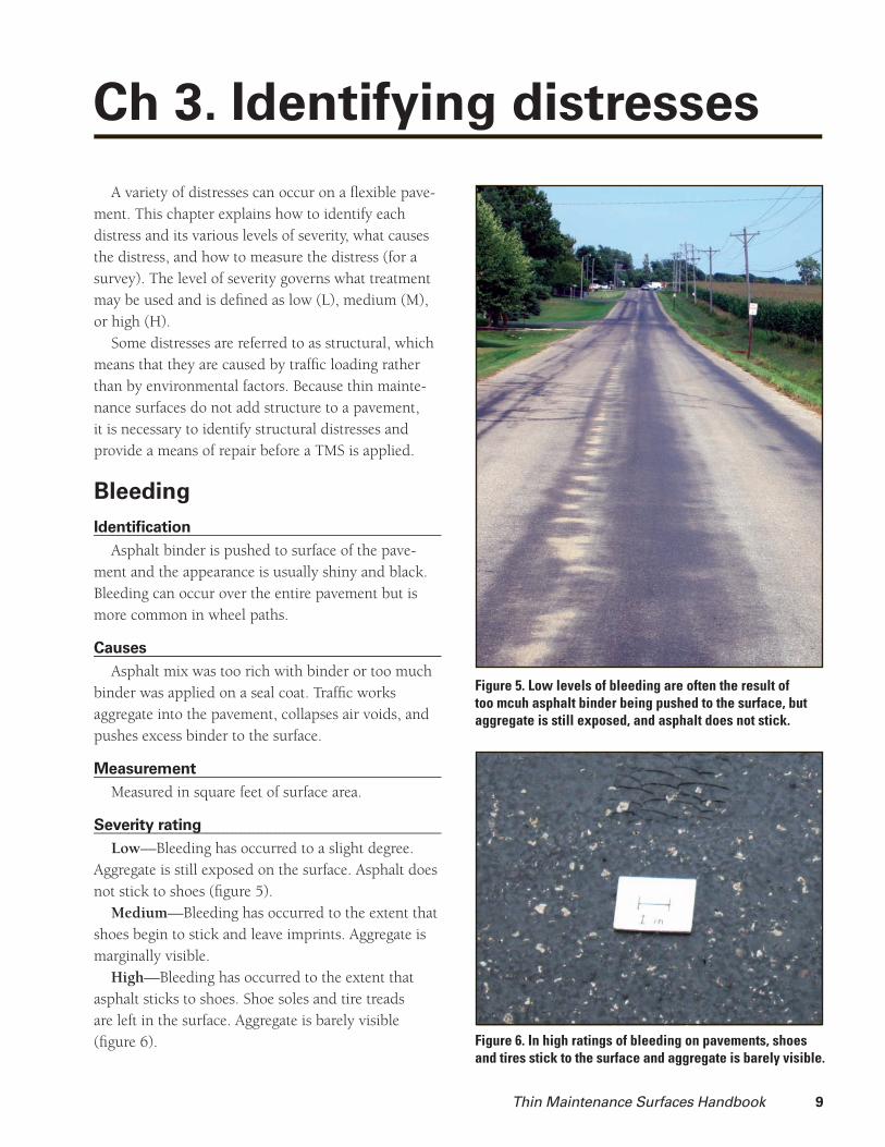
Bleeding
Identifi cation ________________________________________Asphalt binder is pushed to surface of the pave-
ment and the appearance is usually shiny and black. Bleeding can occur over the entire pavement but is more common in wheel paths.
Causes________________________________________Asphalt mix was too rich with binder or too much
binder was applied on a seal coat. Traffi c works aggregate into the pavement, collapses air voids, and pushes excess binder to the surface.
Measurement ________________________________________Measured in square feet of surface area.
Severity rating________________________________________Low—Bleeding has occurred to a slight degree.
Aggregate is still exposed on the surface. Asphalt does not stick to shoes (fi gure 5).
Medium—Bleeding has occurred to the extent that shoes begin to stick and leave imprints. Aggregate is marginally visible.
High—Bleeding has occurred to the extent that asphalt sticks to shoes. Shoe soles and tire treads are left in the surface. Aggregate is barely visible (fi gure 6).
Ch 3. Identifying distresses
Figure 5. Low levels of bleeding are often the result of too mcuh asphalt binder being pushed to the surface, but aggregate is still exposed, and asphalt does not stick.
Figure 6. In high ratings of bleeding on pavements, shoes and tires stick to the surface and aggregate is barely visible.

10 Thin Maintenance Surfaces Handbook
Bumps and sags
Identifi cation________________________________________Bumps are small, localized bulges of the pavement
surface. Sags are small, abrupt depressions of the pavement surface.
Causes________________________________________Bumps and sags are caused by buckling or bulging
of underlying PCC slabs or frost heave.
Measurement________________________________________Measured in lineal feet.
Severity rating ________________________________________Low—Causes small problems with ride quality.Medium—Causes moderate problems with ride
quality.High—Cause major problems with ride quality.
Cracking
Alligator cracking
Identifi cation________________________________________Alligator cracking is a structural distress composed
of interconnected cracks that have the appearance of alligator scales. Alligator cracking is typically found in wheel paths and may be accompanied by rutting.
Causes________________________________________Alligator cracks form in areas of repeated traffi c
loads. The traffi c loads cause high stress in the bottom of the pavement. This stress cracks the pavement start-ing from the bottom and working up to the surface. The cracking begins with hairline longitudinal cracks in the wheel paths and, as the pavement ages, the cracks begin to interconnect and form small blocks.
Measurement________________________________________Measured in square feet of surface area.
Severity rating________________________________________Low—Longitudinal cracks have formed, but few
interconnecting cracks have formed. Cracks are tight and have not spalled. Pavement does not pump under loading (fi gure 7).
Figure 7. Low levels of alligator cracking begin with a few hairline longitudinal cracks, but pavement do not pump under loading.
Medium—Cracks are beginning to form small blocks. Cracks are beginning to spall. Pavement does not pump under loading.
High—A dense network of cracks has formed. Cracks have spalled. Pavement pumps when loaded (fi gure 8).
Block cracking
Identifi cation________________________________________Cracks form large rectangles in the pavement. The
blocks range from 1–10 square feet. Block cracking usually occurs over the entire pavement, not just in wheel paths. Block cracking is not an indication of structural failure.
Causes________________________________________Block cracking is caused by the shrinkage of the
pavement due to daily temperature cycling. It most commonly appears in desert climates where there are wide differences between daytime and nighttime temperatures.

Thin Maintenance Surfaces Handbook 11
Figure 8. High alligator cracking is a network of cracks that have formed and grown into blocks. Areas where dense cracks have formed pump when loaded.
Figure 9. High block cracking ratings are those with cracks wider than 3/4 inch that are spalling. They occur over in large rectangles over the entire pavement.
Measurement________________________________________Measured in square feet of surface area.
Severity rating________________________________________Low—Cracks are less than ¼ inch wide or have
been sealed (and seal is still in good condition).Medium—Cracks are ¼ to ¾ inch wide.High—Cracks are wider than ¾ inch and are spall-
ing (fi gure 9).
Edge cracking
Identifi cation________________________________________Cracks along the edge of the pavement near the
shoulder.
Causes________________________________________Cracks can be caused by inadequate support, sub-
base failure due to water intrusion, and traffi c loading.
Measurement________________________________________Measured in lineal feet.
Severity rating________________________________________Low—Cracks are ¼ inch wide or less, with no
breakup or raveling.Medium—Cracks are ¼ to ¾ inch wide with some
breakup and raveling.High—Considerable breakup or raveling along the
edge.
Joint refl ection cracking
Identifi cation________________________________________Cracks mirror joints in an underlying overlay or
PCC pavement. Cracks are usually very straight and intersect at right angles.
Causes________________________________________When the joints in the underlying layers move,
the surface layer moves and refl ects the joint cracks. Movement of the underlying pavement may be vertical, caused by traffi c, or horizontal, caused by shrinkage.

12 Thin Maintenance Surfaces Handbook
Measurement________________________________________Measured in lineal feet.
Severity rating________________________________________Low—Cracks are less than ¼ inch wide or have
been sealed (and seal is still in good condition).Medium—Cracks are ¼ to ¾ inch wide (fi gure 10).High—Cracks are wider than ¾ inch and/or
spalling.
Longitudinal cracking
Identifi cation________________________________________Cracks parallel to the direction of traffi c. The cracks
are commonly located in wheel paths and at construc-tion joints (fi gure 11). These cracks indicate structural failure.
Causes________________________________________Some cracks form at the bottom of the pave-
ment layer under the wheel path and propagate to the surface. Other cracks are formed at construction joints and are caused by a lack of fi ne aggregate at the surface or poor compaction resulting in a weak bond between the two pavements. Still other longitudinal cracks are caused by paving machine–induced seg-regation. Sometimes paving machines place excess coarse aggregate in the middle of the screed where the augers are attached to the auger drive shaft. Longi-tudinal cracks sometimes appear above this coarse aggregate.
Measurement________________________________________Measured in lineal feet.
Severity rating________________________________________Low—Cracks are less than ¼ inch wide or have
been sealed (and seal is still in good condition).Medium—Cracks are ¼ to ¾ inch wide (fi gure 12).High—Cracks are wider than ¾ inch and/or
spalling.
Transverse/thermal cracking
Identifi cation________________________________________Transverse cracks run perpendicular to the direc-
tion of the road. These cracks typically start at the top and move towards the bottom.
Figure 10. Medium ratings of joint refl ection cracking, cracks that mirror joints, are those with cracks 1/4 to 3/4 inch wide.
Figure 12. Medium ratings of longitudinal cracking, cracks that parallel the direction of traffi c, are those with cracks 1/4 to 3/4 inch wide.
Figure 11. Longitudinal cracking can occur down the centerline where construction joints intersect, parallel to the direction of traffi c.

Thin Maintenance Surfaces Handbook 13
Causes________________________________________Transverse cracks are typically caused by the ther-
mal shrinkage of the pavement.
Measurement________________________________________Measured in lineal feet.
Severity rating________________________________________Low—Cracks are of low severity. Cracks are less
than ¼ inch or have been sealed (and seal is still in good condition).
Medium—Cracks are of medium severity. Cracks are between ¼ inch and ¾ inch (fi gure 13).
High—Cracks are of high severity. Cracks are wider than ¾ inch and are spalling (fi gure 14).
Oxidation
Identifi cation________________________________________Surface of the pavement is a light gray. Surface
binder is brittle. Aggregate can be easily removed from the surface (fi gure 15).
Figure 13. Medium ratings of transverse cracking, cracks that run perpendicular to the direction of the road, are those with cracks 1/4 to 3/4 inch wide.
Figure 14. High severity ratings of transverse cracking are wider than 3/4 inch wide and are spalling.
Figure 15. Oxidation of pavement is caused by exposure to the sun and to water, causing binder to become brittle.
Causes________________________________________Ultraviolet rays from the sun. Exposure to water.
Measurement________________________________________The entire surface of the pavement will be oxidized.
Severity rating________________________________________None.
14 Thin Maintenance Surfaces Handbook
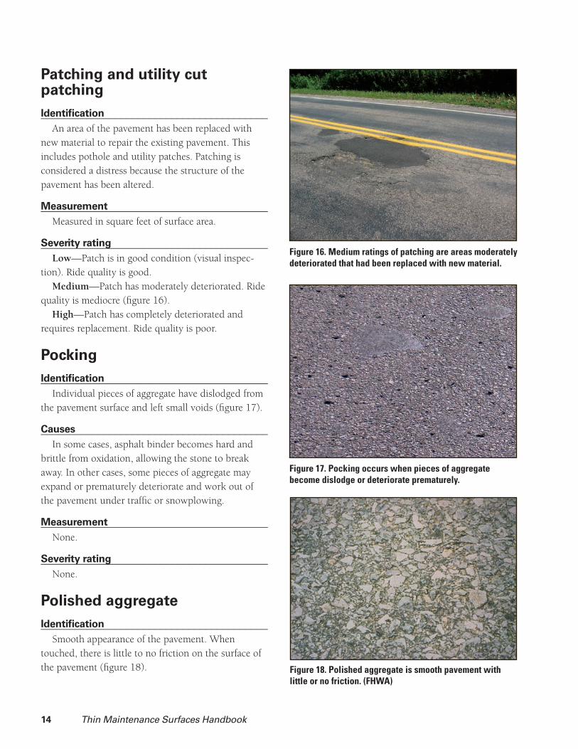
Patching and utility cut patching
Identifi cation________________________________________An area of the pavement has been replaced with
new material to repair the existing pavement. This includes pothole and utility patches. Patching is considered a distress because the structure of the pavement has been altered.
Measurement________________________________________Measured in square feet of surface area.
Severity rating________________________________________Low—Patch is in good condition (visual inspec-
tion). Ride quality is good.Medium—Patch has moderately deteriorated. Ride
quality is mediocre (fi gure 16).High—Patch has completely deteriorated and
requires replacement. Ride quality is poor.
Pocking
Identifi cation________________________________________Individual pieces of aggregate have dislodged from
the pavement surface and left small voids (fi gure 17).
Causes________________________________________In some cases, asphalt binder becomes hard and
brittle from oxidation, allowing the stone to break away. In other cases, some pieces of aggregate may expand or prematurely deteriorate and work out of the pavement under traffi c or snowplowing.
Measurement________________________________________None.
Severity rating________________________________________None.
Polished aggregate
Identifi cation________________________________________Smooth appearance of the pavement. When
touched, there is little to no friction on the surface of the pavement (fi gure 18).
Figure 16. Medium ratings of patching are areas moderately deteriorated that had been replaced with new material.
Figure 17. Pocking occurs when pieces of aggregate become dislodge or deteriorate prematurely.
Figure 18. Polished aggregate is smooth pavement with little or no friction. (FHWA)

Thin Maintenance Surfaces Handbook 15
Causes________________________________________Repeated traffi c applications. Aggregate with poor
abrasion resistance.
Measurement________________________________________Measured in square feet of surface area.
Severity rating________________________________________None.
Potholes
Identifi cation________________________________________Bowl-shaped holes in the pavement surface.
Generally, the area surrounding the pothole is alliga-tor cracked. Growth is accelerated by water pooling inside of the hole (fi gure 19 and 20).
Causes________________________________________Poor surface mixtures or structural failure of the
pavement.
Measurement________________________________________Measured by counting the number of low-,
medium-, and high-severity occurrences.
Severity rating:________________________________________
Figure 19. Potholes are a bowl-shaped hole in the pavement surface generally surrounded by alligator cracking.
Figure 20. High severity rated potholes are 1–2+ inches deep and range from 18–30 inches in diameter.
Average Diameter of Pothole
Maximum Depth of Pothole½ to 1 in. 1 to 2 in. > 2 in.
4 to 8 in. Low Low Medium
8 to 18 in. Low Medium Medium
18 to 30 in. Medium High High
Rutting
Identifi cation________________________________________A surface depression runs parallel to traffi c and is
located in the wheel path.
Causes________________________________________There are three possible causes. (1) If the pave-
ment has risen around the edges of the rut, the rut is most likely caused by an unstable mix that fl ows out from under the wheel and moves to the edges. (2) If there are longitudinal cracks at the bottom of the rut, it is most likely caused by structural failure

16 Thin Maintenance Surfaces Handbook
of the sub-base (fi gure 21). (3) If the rut has neither of these characteristics, the rut is likely the result of insuffi cient compaction during construction and subsequent traffi c compaction of the asphalt. After a rut is fully compacted, fi lling it with slurry seal or micro-surfacing can provide a relatively permanent repair. Progressive rutting (rutting that continues to grow deeper and wider) is a result of a poor sub-base or an unstable mix. If rutting is progressive, fi lling with slurry seal or micro-surfacing will only provide a temporary solution.
Measurement________________________________________Measured in square feet of surface area (fi gure 22).
Severity rating________________________________________Low—Ruts are ¼ to ½ inch deep.Medium—Ruts are ½ to 1 inch deep.High—Ruts are >1 inch deep.
Shoving and corrugation
Identifi cation________________________________________A permanent longitudinal displacement of a local-
ized area of a pavement surface. Shoving produces a wave or bump in the asphalt. Shoving failures usu-ally occur on hills, curves, and intersections. Shoving can also occur where an asphalt pavement abuts a concrete pavement. Corrugation is the repetition of shoving and is perpendicular to the direction of traffi c (fi gure 23).
Causes________________________________________Shoving is caused by braking or accelerating
vehicles that displace the asphalt mix. When shov-ing is located at the transition from a PCC to an ACC pavement, it is caused by the thermal expansion of the PCC. The expanding PCC pushes the asphalt pave-ment, causing the distress.
Measurement________________________________________Measured in square feet of surface area.
Severity rating________________________________________Low—Causes small problems with ride quality.Medium—Causes moderate problems with ride
quality.
Figure 21. Longitudinal cracks at the bottom of rutting are often caused by structural failure of the subbase.
Figure 22. Rutting occurs in the wheel path, and is mea-sured in square feet of surface area.
Figure 23. Shoving or corrugation of pavement surface is a longitudinal wave or bump in the asphalt, usually on hills, curves, or intersections.
Thin Maintenance Surfaces Handbook 17
High—Cause major problems with ride quality.
Spalling
Identifi cation________________________________________An existing crack of any type begins to form paral-
lel satellite cracks.
Causes________________________________________Stresses from traffi c cause cracks to roll down near
the edges. When these stresses are too great on the pavement, new cracks begin to form parallel to the old crack.
Measurement________________________________________None.
Severity rating________________________________________None.
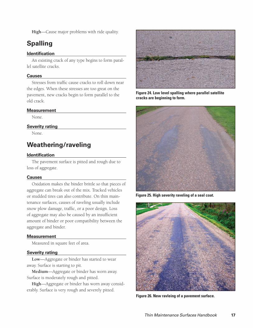
Weathering/raveling
Identifi cation________________________________________The pavement surface is pitted and rough due to
loss of aggregate.
Causes________________________________________Oxidation makes the binder brittle so that pieces of
aggregate can break out of the mix. Tracked vehicles or studded tires can also contribute. On thin main-tenance surfaces, causes of raveling usually include snow plow damage, traffi c, or a poor design. Loss of aggregate may also be caused by an insuffi cient amount of binder or poor compatibility between the aggregate and binder.
Measurement________________________________________Measured in square feet of area.
Severity rating________________________________________Low—Aggregate or binder has started to wear
away. Surface is starting to pit.Medium—Aggregate or binder has worn away.
Surface is moderately rough and pitted.High—Aggregate or binder has worn away consid-
erably. Surface is very rough and severely pitted.
Figure 24. Low level spalling where parallel satellite cracks are beginning to form.
Figure 25. High severity raveling of a seal coat.
Figure 26. New ravleing of a pavement surface.
18 Thin Maintenance Surfaces Handbook
References________________________________________Strategic Highway Research Program (SHRP).
(1993). “Distress identifi cation manual for the Long-Term Pavement Performance Project.” SHRP-P-338, National Research Council, Washington, DC.
Shahin, M. Y. Pavement Management for Airports, Roads, and Parking Lots. Boston: Kluwer Academic Publishers, 1998.
Muench, Stephen. “Pavement Distress.” HAPI Asphalt Pavement Guide. <06-10-05> http://www.hawaiiasphalt.com/HAPI/modules/03_general_guid-ance/03_pavement_distress.htm

Thin Maintenance Surfaces Handbook 19
Ch 4. Treatments at a glanceThe following tables summarize the information
presented about treatment selection in Chapter (7). These tables recommend which surfaces are suit-able for the various distresses and traffi c volumes. However, these tables do not break down the vari-
ous distresses by level of severity. For a more detailed breakdown, refer to the tables for individual surfaces located in Chapter (X). These tables can be taken along on a windshield survey to help start the selec-tion process.
Fog seal Seal coat Slurry seal Micro-surfacing Thin HMA overlay
Traffi c volume:
AADT<2,000
2,000>AADT>5,000 (1) (1)
AADT>5,000 (4) (1)
Bleeding
Rutting
Raveling
CrackingFew tight cracks
Extensive cracks
Alligator cracking
Low friction May improve(3) May improve May improve May improve(2) May improve
Snowplow damage Least susceptible Most susceptible Moderately susceptible Least susceptible Least susceptible
Recommended Not recommended Marginal
1 There is a greater likelihood of sucess when used in lower speed traffi c.2 Micro-surfacing reportedly retains high friction for a longer period of time.3 Fog seal will reduce friction for the fi rst few months until traffi c wears binder of the tops of aggregate4 Not used in Iowa, but other states have seen success.
Micro-surfacing* Slurry seal** Thin HMA overlay NovaChip®
Rut depth
Less than ¼ inch One course One course One course One course
¼ to ½ inch Scratch course and fi nal surface #
One course One course One course
½ to 1 inch Rut box and fi nal surface@
Micro-surfacing scratch course and fi nal surface
Scratch course plus surface course
Mill surface or use another material for scratch course
Greater than 1 inch Multiple placements with rut box
*** Scratch course plus surface course
Mill surface or use another material for scratch course
* As recommended by International Slurry Seal Association** Current practice in Iowa*** Sometimes successful (anecdotal evidence)# Anecdotal evidences suggests that one course may be suffi cient for functionallity, but apperance may be compromised@ Scratch course and surface course have been successfully used in Iowa according to author observations.
Rut d
epth

20 Thin Maintenance Surfaces Handbook

Thin Maintenance Surfaces Handbook 21
Ch 5. Economics of TMS
When selecting a thin maintenance surface, it’s important to compare costs. This chapter provides information on the average costs of TMS in Iowa in 2005. The information came from analyzing inter-views with city engineers, contractors, and material suppliers who place these surface treatments. The wages used are Davis Bacon Wage Rates from 2005.
The cost of traffi c control varies considerably,
depending on the number of traffi c control devices
required. Urban projects may require only a few
cones or barricades to close roads. Rural projects
may require renting or purchasing traffi c control
devices to delineate several miles of road.
Costs were obtained from Flint Hill Resources
(Dan Staebell), Sta-bilt, Inc. (Rick Burchett), the
City of Cedar Rapids (Denny Clift), the City of
Grinnell (Glen Baker), and the City of Des Moines
(Bruce Braun).
Treatment Fog seal Seal coat Slurry seal Micro-surfacing Thin HMA overlayLife expectancy 2–4 years 3–7 years 3–7 years 3–7 years 5–15 years
Cost per square yard $0.10–0.80 $0.80 $0.90 $1.50 $4.40

22 Thin Maintenance Surfaces Handbook
Thin Maintenance Surfaces Handbook 23
Ch 6. Treatment options
Following are descriptions of the various types of thin maintenance surfaces. Included in each is a brief defi nition, a list of the advantages and disadvantages, rules of thumb, equipment list and construction pro-cess, application rates, and a decision matrix.
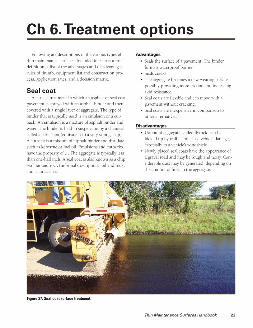
Seal coat A surface treatment in which an asphalt or seal coat
pavement is sprayed with an asphalt binder and then covered with a single layer of aggregate. The type of binder that is typically used is an emulsion or a cut-back. An emulsion is a mixture of asphalt binder and water. The binder is held in suspension by a chemical called a surfactant (equivalent to a very strong soap). A cutback is a mixture of asphalt binder and distillate, such as kerosene or fuel oil. Emulsions and cutbacks have the property of.… The aggregate is typically less than one-half inch. A seal coat is also known as a chip seal, tar and rock (informal description), oil and rock, and a surface seal.
Advantages________________________________________Seals the surface of a pavement. The binder • forms a waterproof barrier.Seals cracks.• The aggregate becomes a new wearing surface, • possibly providing more friction and increasing skid resistance.Seal coats are fl exible and can move with a • pavement without cracking.Seal coats are inexpensive in comparison to • other alternatives.
Disadvantages________________________________________Unbound aggregate, called fl yrock, can be • kicked up by traffi c and cause vehicle damage, especially to a vehicle’s windshield.Newly placed seal coats have the appearance of • a gravel road and may be rough and noisy. Con-siderable dust may be generated, depending on the amount of fi nes in the aggregate.
Figure 27. Seal coat surface treatment.

24 Thin Maintenance Surfaces Handbook
Because the treatment is one stone thick, it is • not able to fi ll ruts or depressions.Depending on the color of the aggregate, a seal • coat can be a poor background for pavement markings.After multiple lifts of a seal coat, a city street • can develop a high crown, which can be troublesome for vehicles entering or exiting the road via driveways.
Rules of thumb________________________________________Take care when selecting the emulsion. Factors • such as aggregate type and quality, construction speed, cost, and expected life should be consid-ered. See Chapter * for material selection.If an emulsion binder is used, it’s critical to • have clean aggregate. If the aggregate is dusty, the emulsion will bond to the dust, not the aggregate. The effect is similar to trying to stick duct tape to a dusty wall.Selecting the proper emulsion application rate • is critical. Too little binder and there won’t be enough to hold the aggregate. Too much binder and the seal coat will bleed. Apply enough binder so that 70 percent of the aggregate is embedded in the binder after the aggregate has been seated with a pneumatic tire roller.Electronically controlled distributors and chip • spreaders are recommended for construc-tion to ensure accurate application rates of the binder and aggregate.Many different design procedures are available • to design the application rates for both binders and aggregates. The Minnesota DOT seal coat manual provides a good explanation for these procedures.When dust must be avoided or when the bind-• er isn’t holding the aggregate, consider using pre-coated aggregate. Pre-coated aggregate has been coated with a thin fi lm of asphalt binder by processing it in a hot mix plant. The coating reduces dust, facilitates a strong bond between the aggregate and emulsion, and gives the seal coat a darker appearance.
Equipment________________________________________Street sweeper• Distributor truck• Chip spreader• Pneumatic tire roller• Dump trucks for material hauling•
Construction process________________________________________Set up traffi c control in accordance with the 1. MUTCD.Sweep the pavement to remove any debris.2. Cover any utility covers with construction 3. paper to make sure the seal coat does not cover them.Make sure all necessary equipment is onsite 4. and properly functioning. Also ensure that the necessary materials are onsite.Make sure the fi rst dump truck is properly 5. attached to the chip spreader.Begin to spray the pavement with the binder 6. using the distributor truck. If a slow setting emulsion is used, approaches or radii at inter-sections should be sprayed fi rst.The chip spreader should then begin to fol-7. low behind the distributor truck.
The following distance should be kept at a. a minimum, especially for rapid-setting cationic emulsions. Most emulsions and cutbacks require chip placement within two to three minutes after the emulsion has been applied or before the surface has turned black. (Emulsions have a dark brown color immediately after they are sprayed from the distributor and turn black as they set and cure.) However, with a high-fl oat emulsion, it is prefer-able to wait until the surface of the emul-sion has formed a skin.
A simple test for whether the binder has b. set is to throw chips across the binder. If the chips stick to the binder, it is okay to apply the chips. If the chips bounce along the binder, the binder has set.

Thin Maintenance Surfaces Handbook 25
The pneumatic tire roller should follow close-8. ly behind the chip spreader. Roll the entire width of the seal coat. Make three passes. If the roller is not able to keep up with the chip spreader, multiple rollers should be used.Return to the site the next day to sweep up 9. excess aggregate.
Application rates________________________________________Binder = 0.20–0.35 gal/yd2
The amount of binder applied to the surface can vary depending on the condition of the pavement. If the pavement is smooth with few voids or small macro-texture (area between pieces of aggregate), reduce the application rate. However, if the pavement is rough with many voids and a deep macro-texture, increase the application rate.
Aggregate = 15–30 lbs/yd2 If the aggregate is spread more than one stone
thick, decrease the application rate. Applying too much aggregate leads to excessive fl y rock, dust, and waste. Extra aggregate requires additional cleanup and haul costs. If large areas of binder are exposed between pieces of aggregate, apply more aggregate.
Double seal coat Two seal coats are placed consecutively. The
nominal size of the aggregate on the fi rst seal coat is typically one and a half to two times the nominal size of the second layer.
Advantages________________________________________Adds more waterproofi ng to the surface in • comparison to a single seal coat.Seals cracks to a greater degree than a single • seal coat.Is more robust than a single seal coat.• Other advantages are the same as those for a • single seal coat.
Disadvantages________________________________________Has a higher risk of bleeding if the emulsion • application rate is too high.Added cost of extra material and labor for the • construction.Other disadvantages are the same as those for a • single seal coat.
Rules of thumb________________________________________The proper emulsion application rate is critical • to success.
Figure 28. Double seal coat surface treatment.

26 Thin Maintenance Surfaces Handbook
Other rules of thumb are the same as those for • a single seal coat.
Construction process________________________________________Use the seal coat construction process.
Application rates________________________________________Use a seal coat design procedure to set the applica-
tion rates for the fi rst pass, except reduce the amount of aggregate slightly (5–10 percent) to reduce the amount of loose aggregate that will be covered by the second pass. On the second pass, use an emulsion application rate for a rough surface.
Raveling Cracking Rutting Alligator cracking
Low Med. High Low Med High Low Med High Low Med High
** ** ** **
Recommended
* Seal coats are effective on roads with ADT>2,000 but are not commonly used in Iowa.
** Permissible on very low volume roads. Double seal coats will likely be more effective.
(1) There is a greater liklihood of success when used with lower speed traffi c.
(2) Not used in Iowa, but other states have seen success.
Decision matrix for seal coats
Traffi c (ADT) Properties
< 2,000 2,000 < ADT< 5,000. < 5,000 Friction Oxidation
(1) (2)
Life Costs Materials
3–7 yrs. $0.80/yd2 $1070/city block* $11,000/mile** Binders used in Iowa
(0.20–0.35 gal/yd2)
Aggregates used in Iowa
(15–30 lb/yd2)
HFE (high fl oat emulsion) $0.80/gal Limestone $19/ton
CRS (rapid setting emulsion) $0.80/gal Pearock
Cutback (asphalt dissolved in
petroleum solvent)
$1.10–1.15/gal Quartzite
Polymer modifi ed emulsion
Cost of delivery
$0.95/gal
$0.08/gal
Pre-coated chips Add $10/ton
* 1 block = 40 ft. wide pavement x 300 ft.
** 24 ft. wide pavement
See page 7 for source of cost information.

Thin Maintenance Surfaces Handbook 27
Slurry seal A mixture of emulsion, aggregate, water, and
mineral fi ller that is pre-mixed and placed as a slurry onto a pavement. The application of the slurry is only as thick as the largest-sized aggregate. The slurry has the consistency of mud and can be easily worked with hand tools.
Advantages________________________________________Seals the surface of a pavement.• Enhances the appearance of a pavement by pro-• viding a uniform black or gray surface, which is a good background for pavement markings.Provides a new wearing course, restoring fric-• tion and skid resistance. The degree of friction and skid resistance is largely dependent on the quality of the aggregate.Reduces raveling and further oxidation of the • underlying asphalt binder.Fills shallow ruts (full-width pass not necessary).• Levels rolled down cracks.• Fills longitudinal cracks (full-width pass not • necessary).
Figure 29. Slurry seal application.
Disadvantages________________________________________Slurry seal should not be placed on pavementd • that have severe cracking. Because of its brittle nature, the slurry seal will refl ect all the cracks quickly and not provide a water-tight seal. On heavily traffi cked roads, the cracks may spall or widen.The road must be closed for six to eight hours • before traffi c can be allowed onto the surface.
Rules of thumb________________________________________High-quality aggregates are necessary for high-• quality slurry seals.The thickness of the slurry seal is approximate-• ly the same as the largest aggregate size.Use of a rapid-setting emulsion can reduce the • road closure time. Temperature and climate also affect the road closure time: the hotter and drier it is, the sooner the road can be opened to traffi c.If the pavement is experiencing rutting and • the ruts continue to deepen, fi lling them with slurry seal will result in only a temporary improvment.

28 Thin Maintenance Surfaces Handbook
When fi lling ruts, use multiple lifts on deeper • ruts. Use a rut box for the best results. If the ruts are shallow, use a scratch course to level the pavement. (A scratch course is a lift of slurry seal that is placed without fi nishing to fi ll ruts. It is called a scratch course because the spreader will often “scratch” the high spots on the road.) By using a scratch course or a rut box, the fi nal application will be smoother and have a better appearance.Tire noise increases immediately after construc-• tion, but after the slurry seal is traffi cked, the noise levels will drop.Material on high spots of a pavement may ravel • off due to snow plow damage.Wide cracks can be fi lled with slurry to reduce • the width of the crack.
Equipment________________________________________Street sweeper• Slurry mixer and spreader (continuous)• Nurse trucks•
Alternatively, the slurry mixer and nurse truck can be combined into one vehicle, and the spreader can be swapped between trucks. This alternative provides more maneuverability in tight urban areas.
Construction process________________________________________Because of the high cost and specialized nature
of the equipment, slurry seal construction is often
performed by a contractor. Sample specifi cations and quality control procedures are available from the International Slurry Seal Association.
Set up traffi c control in accordance with the 1. MUTCD.Sweep the pavement to remove debris.2. Remove vegetation from cracks.3. Cover any utility covers with construction 4. paper to make sure that the slurry seal does not cover them.Make sure all necessary equipment is onsite 5. and properly functioning. Also ensure that the necessary materials are onsite.Begin by placing the slurry at intersections 6. and radii using hand tools.Place the full-width pass of the slurry on the 7. pavement.Do not allow traffi c on the road until the 8. slurry has cured and does not track.
Application rates________________________________________20–30 lbs/yd2 for a Type III gradation The application rate depends on the gradation of
the aggregate. If a smaller aggregate gradation is used, fewer pounds per square yard are needed for the application.
The mix design should be performed by the con-tractor. Agencies will usually specify the aggregate type and gradation and the specifi c type of binder to be used.
Thin Maintenance Surfaces Handbook 29
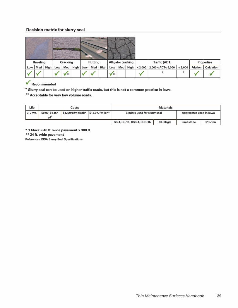
Raveling Cracking Rutting Alligator cracking
Low Med. High Low Med High Low Med High Low Med High
** **
Recommended
* Slurry seal can be used on higher traffi c roads, but this is not a common practice in Iowa.
** Acceptable for very low volume roads.
Decision matrix for slurry seal
Traffi c (ADT) Properties
< 2,000 2,000 < ADT< 5,000. < 5,000 Friction Oxidation
* *
Life Costs Materials
3–7 yrs. $0.90–$1.15/
yd2
$1200/city block* $13,077/mile** Binders used for slurry seal Aggregates used in Iowa
SS-1, SS-1h, CSS-1, CQS-1h $0.80/gal Limestone $19/ton
* 1 block = 40 ft. wide pavement x 300 ft.
** 24 ft. wide pavement
References: ISSA Slurry Seal Specifi cations

30 Thin Maintenance Surfaces Handbook
Micro-surfacing Micro-surfacing is somewhat similar to a slurry seal
in appearance and application but has very different properties. Micro-surfacing is a mixture of polymer-modifi ed emulsion, 100 percent crushed aggregate, water, and mineral fi ller that is pre-mixed and placed as a slurry onto a pavement.
Advantages________________________________________Seals the surface of a pavement.• Enhances the appearance of a pavement by pro-• viding a uniform black or gray surface, which is a good background for pavement markings.Provides a new wearing course, restoring fric-• tion and skid resistance. The degree of friction and skid resistance is largely dependent on the quality of the aggregate.Reduces raveling and further oxidation of the • underlying asphalt binder.Can be used to fi ll ruts up to 1.5 inches deep. Rut • fi lling can be performed without a full-width pass.Can be opened to traffi c within one hour after • application, even in cooler temperatures or at night.
Disadvantages________________________________________After the micro-surfacing has cured, it is brittle • and will refl ect cracks quickly. However, due to the presence of polymers that make the mate-rial more resilient compared to a slurry seal, the cracks will be unlikely to spall after the crack initially refl ects.The ratios of emulsion, aggregate, water, and • mineral fi ller must be kept in a narrow range, which can be troublesome during construction.Compared to slurry seal, there is less time to • perform hand work.
Rules of thumb________________________________________The higher quality the aggregate, the higher • quality the micro-surfacing.Thickness of micro-surfacing is approximately • the same as the largest aggregate size.Micro-surfacing should not be placed on a • pavement that has severe cracking. It will refl ect all the cracks quickly and not provide a watertight seal for them.If the pavement is experiencing rutting and • the ruts continue to deepen, fi lling them with
Figure 30. Micro-surfacing application.

Thin Maintenance Surfaces Handbook 31
micro-surfacing will result in only a temporary improvement.When fi lling ruts, use multiple lifts on deeper • ruts. Use a rut box for the best results. If the ruts are shallow, use a scratch course to level the pavement. (A scratch course is a lift of micro-surfacing that is placed without fi nishing to fi ll ruts. It is called a scratch course because the spreader will often “scratch” the high spots on the road.) By using a scratch course or a rut box, the fi nal application will be smoother and have a better appearance.Tire noise increases immediately after construc-• tion, but after the micro-surfacing is traffi cked, the noise levels will drop.Minnesota DOT requires the construction of • nighttime test sections to ensure micro-surfac-ing quality and prevent substitution of micro-surfacing for a rapid setting slurry seal. This was specifi ed because it was thought that a slurry seal will not cure within an hour at night but that a micro-surfacing will.Material on high spots of a pavement may ravel • off due to snow plow damage.
Equipment________________________________________Street sweeper• Slurry mixer and spreader (continuous)• Nurse trucks•
Alternatively, the slurry mixer and nurse truck can be combined into one vehicle, and the spreader can be swapped between trucks. This arrangement will provide greater maneuverability, which can be desir-able in urban areas.
Construction process________________________________________Because of the high cost and specialized nature
of the equipment, micro-surfacing construction is performed by a contractor. Write specifi cations and perform quality control to ensure quality construction and materials.
Set up traffi c control in accordance with the 1. MUTCD.Sweep the pavement to remove debris.2. Remove vegetation from cracks.3. Cover any utility covers with construction 4. paper to make sure that the slurry seal does not cover them.Make sure all necessary equipment is onsite 5. and properly functioning. Also ensure that the necessary materials are onsite.Begin by placing the micro-surfacing at inter-6. sections and radii using hand tools.Place the full-width pass of the micro-surfac-7. ing on the pavement.Do not allow any traffi c until the slurry has 8. cured and is stable enough for traffi c. With micro-surfacing, this can be done within one hour.
Application rates________________________________________
20–30 lbs/yd2 for a Type III gradation The application rate depends on the gradation of
the aggregate. If a smaller aggregate gradation is used, fewer pounds per square yard are needed for the application.
The mix design should be performed by the con-tractor. Agencies will usually specify the aggregate type and gradation to be used.

32 Thin Maintenance Surfaces Handbook
Raveling Cracking Rutting Alligator cracking
Low Med. High Low Med. High Low Med. High Low Med. High
Recommended
Decision matrix for micro-surfacing
Traffi c (ADT) Properties
< 2,000 2,000 < ADT< 5,000. < 5,000 Friction Oxidation
Life Costs Materials
3–7 yrs. $1.50/yd2 $2,000/city block* $21,000/mile** Binders used for micro-surfacing Aggregates used in Iowa
CRS-2P $0.95/gal Limestone $19/ton
Ralumac® Portland cement
(mineral fi ller)
$1.30/gal Quartzite
Potable water* 1 block = 40 ft. wide pavement x 300 ft.
** 24 ft. wide pavement
Thin Maintenance Surfaces Handbook 33
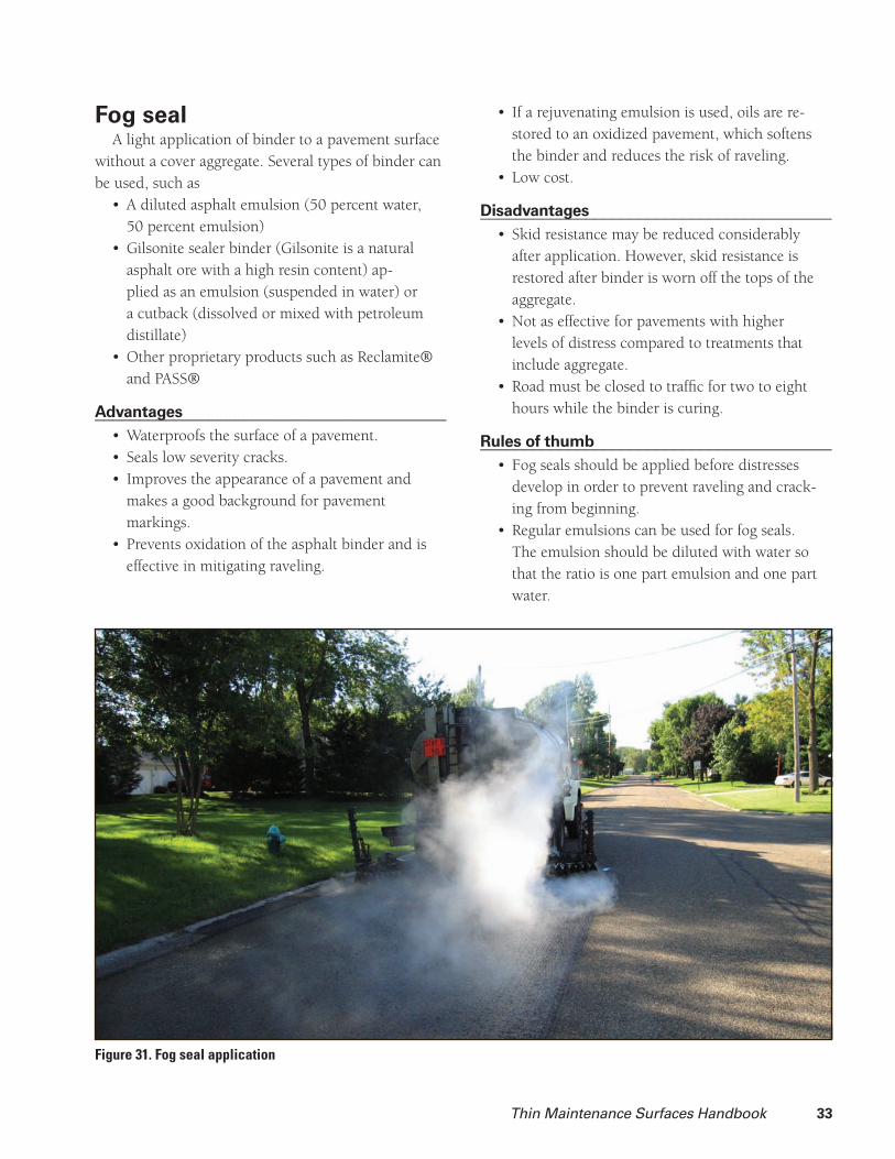
Fog seal A light application of binder to a pavement surface
without a cover aggregate. Several types of binder can be used, such as
A diluted asphalt emulsion (50 percent water, • 50 percent emulsion) Gilsonite sealer binder (Gilsonite is a natural • asphalt ore with a high resin content) ap-plied as an emulsion (suspended in water) or a cutback (dissolved or mixed with petroleum distillate)Other proprietary products such as Reclamite® • and PASS®
Advantages________________________________________Waterproofs the surface of a pavement.• Seals low severity cracks.• Improves the appearance of a pavement and • makes a good background for pavement markings.Prevents oxidation of the asphalt binder and is • effective in mitigating raveling.
If a rejuvenating emulsion is used, oils are re-• stored to an oxidized pavement, which softens the binder and reduces the risk of raveling.Low cost.•
Disadvantages________________________________________Skid resistance may be reduced considerably • after application. However, skid resistance is restored after binder is worn off the tops of the aggregate.Not as effective for pavements with higher • levels of distress compared to treatments that include aggregate.Road must be closed to traffi c for two to eight • hours while the binder is curing.
Rules of thumb________________________________________Fog seals should be applied before distresses • develop in order to prevent raveling and crack-ing from beginning.Regular emulsions can be used for fog seals. • The emulsion should be diluted with water so that the ratio is one part emulsion and one part water.
Figure 31. Fog seal application

34 Thin Maintenance Surfaces Handbook
Use blotting sand to increase skid resistance • shortly after application.Rejuvenating emulsions can be used on pave-• ments that are severely oxidized to restore oils to the surface.
Equipment________________________________________Street sweeper• Distributor truck•
Construction process________________________________________Set up traffi c control in accordance with the 1. MUTCD.Sweep the pavement to remove debris.2. Cover any utility covers with construction pa-3. per to make sure the fog seal does not cover them.
Make sure all necessary equipment is onsite 4. and properly functioning. Check to make sure that the nozzles are properly aligned and the spray bar is at the correct elevation to minimize streaking in the application.Begin by spraying any intersections or radii.5. Spray the entire width of the pavement. If 6. possible, spread sand from the distributor truck to increase friction.Do not allow any traffi c on the fog seal until it 7. has cured.
Application rates________________________________________As low as 0.03 gal/yd2 for a pavement with a tight
surface and as high as 0.22 gal/yd2 for a pavement with a more porous surface. Application rate of the sand is 2 lb/yd2.
Raveling Cracking Rutting Alligator cracking
Low Med. High Low Med. High Low Med. High Low Med. High
Recommended
Decision matrix for fog seal
Traffi c (ADT) Properties
< 2,000 2,000 < ADT< 5,000. < 5,000 Friction Oxidation
Life Costs Materials
2–5 yrs. $0.18–0.80/yd2 $250–1,100/city block* $2,500–11,000/mile** Binders used for fog seal
CRS $0.80/gal (before dilution)
HFRS $.80/gal (before dilution)
Rejuvinators increase the cost of the fog seal* 1 block = 40 ft. wide pavement x 300 ft.
** 24 ft. wide pavement

Thin Maintenance Surfaces Handbook 35
Smooth seal A thin HMA overlay typically one to two inches
thick placed over an existing seal coat road. A seal coat road that has been in place for several years and shows little distress can serve as an excellent base for this treatment. A smooth seal can also be placed over gravel roads provided that they have adequate structure.
Advantages________________________________________Provides a surface that is similar to that of a • full-depth HMA road.Provides a smooth, quiet surface that accom-• modates inline skates, skateboards, and bikes.Eliminates the need to place seal coats • periodically.Although design calculations assume that • smooth seal does not add structure to the pave-ment, in actuality, it may add a small amount of structure which may be helpful.
Disadvantages________________________________________Initial cost of construction can be high.• Limited to use on low-volume roads with lim-• ited truck traffi c.
Figure 32. Smooth seal overlay on existing seal coat road.
Does not remove crown from the seal coat.• Requires adjustment of utility covers.•
Rules of thumb________________________________________The overlay only needs to be one inch thick on • residential pavements. Two inches or thicker should be used for any roads that experience truck traffi c.Do routine maintenance to extend the life of • the overlay. Crack sealing is especially impor-tant because the structure of the underlying seal coat will be severely compromised by moisture infi ltration.Replace any areas of structural defi ciency with • a full-depth patch before constructing the smooth seal.Maintain or construct proper drainage to pre-• vent moisture from saturating the sub-base.The thin HMA will cool quickly. This loss of • temperature can make proper compaction dif-fi cult to obtain.
Equipment________________________________________Street sweeper• Distributor truck•

36 Thin Maintenance Surfaces Handbook
Asphalt paver• Pneumatic tire rollers • Steel rollers•
Construction process________________________________________HMA overlays are typically performed by contrac-
tors. Write specifi cations and perform quality control to ensure quality construction and materials.
Set up traffi c control in accordance with the 1. MUTCD. (This step may need to be repeated more than once if steps 2, 3, and 4–7 are separate operations.)Address drainage problems.2. Adjust utility covers to proposed pavement 3. height.Sweep the pavement.4. Make sure all necessary equipment is onsite 5. and properly functioning.Apply the tack coat.6. Place the HMA mat.7.
Use the vibratory steel rollers for the initial 8. compaction, pneumatic tire rollers for the second stage, and static steel rollers for the fi nal stage. Thin overlays tend to cool quickly, so the rollers must keep up with the paver. Monitor temperatures to ensure that the mix is being properly compacted.Open road to traffi c when the pavement has 9. cooled.
Application rates________________________________________One inch of HMA for pavements with light resi-
dential traffi c. Two inches of HMA for pavements with light truck traffi c. Tack coat application is usually 0.02–0.10 gal/yd2.
The contractor should design the mix. Typically, contractors will have a pre-determined mix that is suitable for this type of surface.
Raveling Cracking Rutting Alligator cracking
Low Med. High Low Med. High Low Med. High Low Med. High
Recommended
Decision matrix for smooth seal
Traffi c (ADT) Properties
< 2,000 2,000 < ADT< 5,000. < 5,000 Friction Oxidation
Life Costs Materials
5–15 yrs. $3–6/yd2* $1,600–2,000/city block** $28,000–42,000/mile*** Hot mix asphalt Cost is dependent on the price of
HMA/ton (in-place)
To calculate cost/yd2: Multiply $/ton x
0.056 x depth of overlay (in.)
* Assumes $55/ton of HMA for 1 in. and 2 in. overlays
** 1 block = 24 ft. wide pavement x 300 ft.
*** 24 ft. wide pavement
Thin Maintenance Surfaces Handbook 37
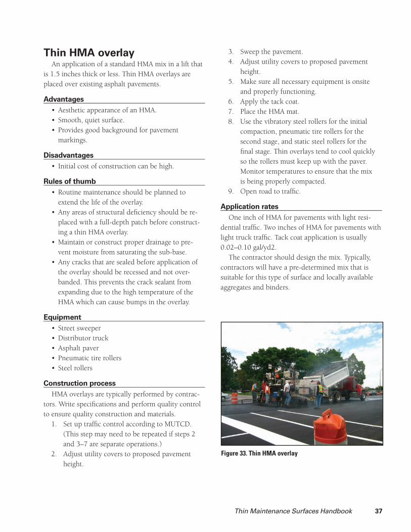
Thin HMA overlay An application of a standard HMA mix in a lift that
is 1.5 inches thick or less. Thin HMA overlays are placed over existing asphalt pavements.
Advantages________________________________________Aesthetic appearance of an HMA.• Smooth, quiet surface.• Provides good background for pavement • markings.
Disadvantages________________________________________Initial cost of construction can be high.•
Rules of thumb________________________________________Routine maintenance should be planned to • extend the life of the overlay. Any areas of structural defi ciency should be re-• placed with a full-depth patch before construct-ing a thin HMA overlay.Maintain or construct proper drainage to pre-• vent moisture from saturating the sub-base.Any cracks that are sealed before application of • the overlay should be recessed and not over-banded. This prevents the crack sealant from expanding due to the high temperature of the HMA which can cause bumps in the overlay.
Equipment________________________________________Street sweeper• Distributor truck• Asphalt paver• Pneumatic tire rollers • Steel rollers•
Construction process________________________________________HMA overlays are typically performed by contrac-
tors. Write specifi cations and perform quality control to ensure quality construction and materials.
Set up traffi c control according to MUTCD. 1. (This step may need to be repeated if steps 2 and 3–7 are separate operations.)Adjust utility covers to proposed pavement 2. height.
Figure 33. Thin HMA overlay
Sweep the pavement.3. Adjust utility covers to proposed pavement 4. height.Make sure all necessary equipment is onsite 5. and properly functioning.Apply the tack coat.6. Place the HMA mat.7. Use the vibratory steel rollers for the initial 8. compaction, pneumatic tire rollers for the second stage, and static steel rollers for the fi nal stage. Thin overlays tend to cool quickly so the rollers must keep up with the paver. Monitor temperatures to ensure that the mix is being properly compacted.Open road to traffi c.9.
Application rates________________________________________One inch of HMA for pavements with light resi-
dential traffi c. Two inches of HMA for pavements with light truck traffi c. Tack coat application is usually 0.02–0.10 gal/yd2.
The contractor should design the mix. Typically, contractors will have a pre-determined mix that is suitable for this type of surface and locally available aggregates and binders.

38 Thin Maintenance Surfaces Handbook
Raveling Cracking Rutting Alligator cracking
Low Med. High Low Med. High Low Med. High Low Med. High
Recommended
Decision matrix for HMA overlay
Traffi c (ADT) Properties
< 2,000 2,000 < ADT< 5,000. < 5,000 Friction Oxidation
Life Costs Materials
5–15 yrs. $3–6/yd2* $1,600–2,400/city block** $28,000–42,000/mile*** Hot mix asphalt Cost is dependent on the price of
HMA/ton (in-place)
To calculate cost/yd2: Multiply $/ton x
0.056 x depth of overlay (in.)
* Assumes $55/ton of HMA for 1 in. and 2 in. overlays
** 1 block = 24 ft. wide pavement x 300 ft.
*** 24 ft. wide pavement
References: CalTrans Maintenance Manual Chapter 8: Maintenance Overlays

Thin Maintenance Surfaces Handbook 39
NovaChip®Thin course (less than 3/4 in.) open-graded aggre-
gate hot mix asphalt over a binder membrane called
NovaBond™. NovaChip® goes down with a special paver that applies both a thick tack coat and the HMA
in one pass. NovaChip® is purported to provide a
water resistant membrane in a manner similar to that
of a seal coat without the disadvantage of fl y rock. A
few projects in Iowa have been constructed using this
proprietary process, mostly as demonstration projects.
Advantages________________________________________Improves the aesthetic appearance of an HMA.• Provides smooth, quiet surface.• Because surface is porous, water spray during • rain is reduced considerably.Reduces headlight glare on rainy nights.• Provides good background for pavement • markings.Can be opened to traffi c immediately after • construction.
Disadvantages________________________________________Initial cost of construction can be high.• Possible free/thaw damage due to water getting • trapped in porous surface.Drainage must be provided at low edge of road • to allow water to exit, which may be diffi cult where curb and gutter are used.Diffi culty in providing feathered edges at utility • covers and construction joints.
Rules of thumb________________________________________NovaChip® can be used to fi ll ruts up to ½ in. • on the fi rst pass. If the ruts are deeper, pave-ment surface should be milled down to reduce rut depth or a scratch course of slurry seal, micro-surfacing, or HMA should be placed to fi ll the ruts.
Equipment________________________________________Street sweeper• NovaChip® paver•
Figure 34. NovaChip® application.
Construction process________________________________________Set up traffi c control according to MUTCD. 1. (This step may need to be performed more than once if steps 2 and 3–7 are separate operations.)Adjust utility covers to new pavement height.2. Sweep the pavement to remove any large 3. debris.Cover any utility covers with construction 4. paper to make sure the NovaBond™ does not cover the manholes.Make sure all necessary equipment is onsite 5. and properly functioning.
Place the NovaChip6. ® over the NovaBond™ in one pass.Seat and orient aggregate with one or two 7. passes of a static-steel wheeled roller.Open road to traffi c.8.
*NovaChip® must be placed by a contractor who is licensed to place this proprietary product. However, quality control should be performed and specifi cations should be written so as to ensure quality construction and materials.
Application rates________________________________________The mix design will be performed by the
contractor.
40 Thin Maintenance Surfaces Handbook
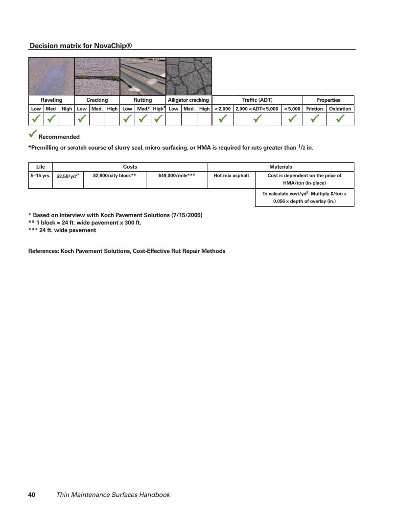
Raveling Cracking Rutting Alligator cracking
Low Med. High Low Med. High Low Med. High Low Med. High
Recommended
Decision matrix for NovaChip®
Traffi c (ADT) Properties
< 2,000 2,000 < ADT< 5,000. < 5,000 Friction Oxidation
Life Costs Materials
5–15 yrs. $3.50/yd2* $2,800/city block** $49,000/mile*** Hot mix asphalt Cost is dependent on the price of
HMA/ton (in-place)
To calculate cost/yd2: Multiply $/ton x
0.056 x depth of overlay (in.)
* Based on interview with Koch Pavement Solutions (7/15/2005)
** 1 block = 24 ft. wide pavement x 300 ft.
*** 24 ft. wide pavement
References: Koch Pavement Solutions, Cost-Effective Rut Repair Methods
* *
*Premilling or scratch course of slurry seal, micro-surfacing, or HMA is required for ruts greater than 1/2 in.

Thin Maintenance Surfaces Handbook 41
Often there is not a clear best choice for a TMS treatment. Each TMS has advantages and disadvan-tages, depending on a pavement’s distresses. This can make the decision process diffi cult.
Multiple factors will infl uence the fi nal decision of the surface to be used:
Type of distress • Aesthetics• Initial cost• Life cycle costs• Availability of materials•
Type of distress________________________________________Certain treatments are better for some distresses
than others. For example, if the surface is cracked, a more fl exible treatment such as a seal coat is most effective, since it can reduce water intrusion into cracks to a greater extent than a stiffer treatment such as slurry seal or micro-surfacing. However, for rut fi lling, stiffer treatments such as slurry seal or micro-surfacing are more effective. Therefore, the treatment must be selected to match the distress.
Aesthetics________________________________________The appearance of the road will be important to
neighboring property owners, some road users, and many others in the community. Consider preferences in aggregate color and texture that stakeholders may have.
Initial costs________________________________________Most maintenance programs have to fi t within an
annual budget. If a certain amount of road must be maintained, this may limit the choices available to the decision maker.
Life cycle costs________________________________________Decisions about maintenance investments can
have impacts on future maintenance and construc-tion costs. It may be possible to delay a construction project and invest the funding in maintenance, thereby delaying the need for future rehabilitation and construction. On the other hand, a well-selected
Ch 7. Selecting the treatmentreconstruction or rehabilitation project might reduce future maintenance costs. Decision makers should consider how their decisions will affect the costs for the entire life cycle of the road.
Availability of materials________________________________________Transportation of aggregates is very expensive in
comparison to their value in a stockpile at the quarry. For this reason, decision makers often decide to limit their choices to locally available aggregates. Rail or barge transportation may provide opportunities to ship aggregates longer distances. In addition, asphalt suppliers provide a limited number of emulsions and, like aggregate, the cost of transportation is high in comparison to the value of the product. So, as with aggregates, decision makers will be limited in the variety of emulsions and other binders that they can specify.
Availability of contractors and equipment________________________________________Mobilization costs can be high and scheduling can
be diffi cult for contractors who are not local to the area. Therefore, decision makers may decide to use treatments that can be applied by local contractors. If the work is performed by a government agency using their own workers and equipment, decision makers may be limited to methods and materials that can be applied using those resources.
Repetition and economics of scale________________________________________Many jurisdictions settle on a limited number of
treatments that work well for them, then repeat those treatments on a regular basis (e.g., once every one to fi ve years). Mobilizing to provide a small amount of a particular treatment that is not one of those regularly used may be uneconomical or administratively chal-lenging. Therefore, decision makers will often rely on treatments that are in their usual repertoire as much as possible. However, by being in the habit of using a particular treatment, decision makers run the risk of misapplying that treatment or not realizing that it might be economical to use a different treatment.

42 Thin Maintenance Surfaces Handbook
Common HMA pavement conditions
The examples in this section illustrate common HMA pavement conditions and suggest possible thin maintenance surface selections. See Figure 1.
HMA No. 1: Excellent to very good condition________________________________________Pavement is slightly to moderately oxidized and • is beginning to pock or ravel in low severity. Thermal cracks have formed but are still thin • (hairline to ¼ inch), or joints cracks from underlying pavement have refl ected and are of low severity. There is no indication of structural failure. •
In this example, because there is little distress, all thin maintenance surfaces could be considered for preventive maintenance. However, from the perspec-tive of road users, thin maintenance surfaces other than fog seal may result in a rougher road texture that would be considered undesirable. Nevertheless, the benefi ts of arresting oxidation and waterproofi ng the surface may extend pavement life suffi ciently to justify an investment in maintenance. Many of these benefi ts can also be obtained with a fog seal.
PreconstructionCracks should be sealed two to three months before
construction.
Surfaces suitable for this pavementFog seal—Recommended if the distresses are of
low severity. Fog seal is effective for waterproofi ng the surface
of the pavement, mitigating raveling, and sealing thin cracks. Fog seal also restores a dark color that resembles a new asphalt pavement and is a good back-ground for pavement markings.
Note: A fog seal will reduce friction until the binder has been worn off the tops of the exposed aggregate. Applying sand can help to restore the friction. Also, the road will have to be closed until the emulsion has cured, which can take up to eight hours, depending on the weather.
Slurry seal, micro-surfacing—Recommended if pavement is moderately oxidized or pocked. Effective at sealing all of the distresses described in this exam-
ple and provides a new high-friction wearing course. Slurry seals can be used in place of a seal coat with
little added cost. The slurry seal has the advantage of a higher aesthetic value over the seal coat. Also, if the pavement has low-severity and low-density cracking, the slurry seal will perform well.
Compared to a slurry seal, micro-surfacing may have a longer service life, but the cost of micro-surfac-ing is higher than that of a slurry seal.
Seal coat—Recommended with caution. Although seal coat will likely extend pavement life, it may have limited acceptance by road users, neighboring property owners, and other stakeholders. High-qual-ity application techniques, smaller aggregate, and premium materials are recommended if seal coat is applied to a pavement that is in good condition.
The seal coat will provide a new wearing course which can restore friction to an existing low-fric-tion surface. Well-maintained surfaces can be sealed with ¼ to 3/8 aggregate. This reduces materials costs, because less binder is required to attach the smaller particles. The smaller aggregate also results in a smoother road. Avoid using uncrushed aggregate such as pea rock. The round shape makes it more likely to roll on the pavement, causing raveling of the seal coat. When lighter color aggregates are used, the seal coat gives the appearance of a gravel road, and it can be very dusty if the aggregate has excessive fi nes. Using pre-coated chips will prevent dust problems and give the seal coat an appearance closer to that of an HMA road. The pre-coated chips also form a stronger bond with the binder, which decreases raveling.
Surfaces not recommended for this pavementThin HMA overlay, smooth seal, NovaChip®—
Not recommended. Given the good condition of the pavement in this example, investment in these sur-faces is likely to be premature.
HMA No. 2: Good to fair condition________________________________________The pavement surface is oxidized and is ravel-• ing or pocking. Areas of polished aggregate are beginning to • form. Thermal cracks and/or joint refl ection cracks • are beginning to widen or spall.

Thin Maintenance Surfaces Handbook 43
Rutting, if present, is shallow. • A centerline crack has formed. •
Treatments placed on roads in this condition are maintenance treatments, not preventive maintenance.
PreconstructionCracks should be sealed two to three months before
construction.
Surfaces suitable for this pavementSeal coat—Recommended if rutting does not
exceed moderate severity.Ruts between ¼ and 1 inch deep can be reduced by
fi lling them with slurry seal (see below). After the ruts are fi lled, a seal coat may be placed over the entire road to provide a uniform surface.
A seal coat effectively provides a waterproof sur-face to mitigate raveling, and it also seals thermal, refl ected, and centerline cracks. A seal coat will also restore friction to a pavement with polished aggregate or low friction. Consider using a double seal coat or a cape seal to increase the robustness of the seal coat against distresses.
Slurry seal, micro-surfacing—Recommended. Both slurry seal and micro-surfacing will provide a
waterproof seal and good friction. They also make the pavement look like an HMA pavement and provide a good background for pavement markings. A slurry seal is recommended for pavements with low severity cracks that are not spalling. Because slurry seals are brittle, the surface will quickly refl ect cracks, which may widen or spall. Micro-surfacing is more resilient and less likely to widen or spall at crack locations.
For rounded-over cracks, use either the slurry seal or micro-surfacing to level and fi ll in the crack before the entire surface is sealed. This will mitigate crack spalling and also restore a smoother ride to the pavement.
For ruts up to one inch deep, a good slurry seal mix can fi ll them when carefully placed. For deeper ruts under higher traffi c, micro-surfacing is more stable and a more reliable choice. However, well-designed and placed slurry seal has reportedly successfully fi lled ruts deeper than one inch.
Both surfaces will have a higher tire noise until the
aggregate in the seal is laid fl at by traffi c. The cost of a slurry seal is only slightly higher than a seal coat. The cost of micro-surfacing is one and a half to two times as expensive as a seal coat.
Thin HMA, smooth seal, NovaChip®—Recom-mended for the same reasons as the slurry seal and micro-surfacing.
These surfaces are effective at fi lling ruts. Although the design assumption is that these surfaces do not add structure, in actuality they do add a marginal amount of structure that can be helpful in life exten-sion. Any cracking will refl ect through to the new surface. These surfaces will provide a smooth ride and good appearance. In comparison to other treatments, these surfaces restore a completely “new road” look and feel and will likely last longer. The cost will be higher.
Surfaces not recommended for this pavementFog seal—Not recommended.
HMA No. 3: Fair to poor condition________________________________________Pavement is oxidized and is raveling and • pocking. The cracks in the pavement are wide and have • spalled. Rutting is ½ to 1 inch deep, and longitudinal • cracks are beginning to form in the rut. The centerline crack is spalling. • Low-severity alligator cracking is beginning to • form in the wheel paths.
Pavements with these conditions would need to be rehabilitated soon. Thin maintenance surfaces may be used as stopgap treatments, depending on the severity of the distresses, and may delay the need for rehabili-tation. However, such use is rarely economical, and most stakeholders are disappointed by the results.
PreconstructionCheck drainage conditions and make changes if
necessary. Perform full-depth patching for areas with structural failure. Cracks should be sealed two to three months before construction. High spots on the pavement can be milled down with a milling machine, and areas outside the wheel paths can be milled down

44 Thin Maintenance Surfaces Handbook
to decrease depth of ruts. Any potholes should be excavated and replaced with a full-depth patch.
Surfaces suitable for this pavementSeal coat—Possible stopgap life extension
technique. Because seal coats are fl exible and can “glue” the
surface together, they can be an effective stopgap procedure. The seal coat will seal the cracks and waterproof the surface, but it is likely that the cracks will refl ect quickly because the emulsion will soak into the cracks leaving little on the surface to hold the chips. This refl ection can be reduced by pre-seal-ing the cracks before placing the seal coat. Seal coats should not be used if rut fi lling is desired. Seal coats can be marginally effective on alligator cracks if traffi c is light and the cracks don’t pump (proof roll test) under traffi c.
Thin HMA overlay, smooth seal, NovaChip®—Marginally recommended.
These surfaces will add some structure to the pavement and will also fi ll in the ruts. Any areas of alligator cracking should be replaced with a full-depth patch, as the cracking will refl ect quickly. These sur-faces are effective at smoothing out the surface. If ruts are deep or there are variations in the grade, apply a scratch course to fi ll low spots before the surface course is applied.
Surfaces not suitable for this pavementFog seal—Not recommended.Slurry seal, micro-surfacing—Usually not
recommended. If the original pavement has few cracks but has
other distresses such as rutting, raveling, or bleeding, using a slurry seal or micro-surfacing may extend the life somewhat (see the slurry seal section in the HMA No. 2 example). If the cracking is dense and severe, these surfaces are not recommended because all the cracks will refl ect quickly and little improvement will result.
Common seal coat pavement conditions
The examples in this section illustrate common seal coat pavement conditions and suggest possible thin
maintenance surface selections. The deterioration of seal coat pavements differs
from that of HMA pavements because seal coats tend to have less structural capacity and more fl exibility. They are therefore more prone to structural distresses such as rutting of base materials, alligator cracking, and longitudinal cracking in wheel paths. Bleeding and raveling are common when aggregate and binder application rates are not appropriate. Occasionally, seal coat pavements will develop transverse cracks.
Seal coat No. 1: Excellent condition________________________________________Seal coat pavement displays little to no distress. • The only distress might be light-severity ravel-• ing or loss of aggregate.
Surfaces recommended are intended for preventive maintenance.
PreconstructionNone.
Surfaces suitable for this pavementFog seal—Recommended. A fog seal can mitigate light raveling and prevent
more from occurring, because it is gluing the aggre-gate down to the base. It is possible to place a fog seal over a seal coat immediately after the seal coat has been placed to prevent raveling, mitigate dust, and improve the appearance of the pavement. The applica-tion of the fog seal should be designed so as to reduce the likelihood of bleeding. Keep in mind that a fog seal will reduce friction until the binder is worn off the tops of the exposed aggregate. This tendency can be reduced by applying sand. Also, the road will have to be closed until the emulsion has cured, which can take up to eight hours, depending on the weather.
Seal coat—Recommended every one to three years. If the pavement is a full-depth seal coat, place a
new seal coat every one to two years. Even though the seal coat may be in excellent condition, if cracks form and are not sealed, water will quickly weaken the sub-base, causing failure.
Smooth seal—Recommended. Smooth seals are intended to be placed on seal
coats that are in good structural condition. Although the cost is much higher, the smooth seal should last

Thin Maintenance Surfaces Handbook 45
for 7–15 years or more, depending on the amount of traffi c and the strength of the base. It will provide a smooth, clean, and uniform surface. Consider surfac-ing a few blocks per summer while maintaining others with a seal coat.
Slurry seal—Recommended if the existing seal coat is thick and the structural condition is good.
Slurry seal can have better public acceptance in comparison to a seal coat, because there is less dust and fl y rock and the resulting surface is more uniform. On urban streets, layers of seal coat can build up the crown of the road so high that vehicles scrape the road as they enter and exit driveways. A slurry seal provides a thinner layer and slows the buildup of the crown.
Surfaces not suitable for this pavementMicro-surfacing—Not recommended.The extra cost of micro-surfacing is seldom justifi ed
for seal coat pavements which generally experi-ence low traffi c and may have marginal structural characteristics.
Seal coat No. 2: Fair to good condition________________________________________Seal coat is displaying mild bleeding or • raveling. Some cracks have formed. • Ruts are beginning to form. • Alligator cracking is forming and developing • into potholes.
Depending on the amount of work necessary, the surfaces recommended are considered to be mainte-nance or stopgap.
PreconstructionPatch potholes and consider full-depth patches
for areas of alligator cracking. If there are large areas of alligator cracking, check drainage. Consider the possibility that the structure could be improved by improving drainage.
Surfaces suitable for this pavementSeal coat—Recommended. If the seal coat is raveling, a new seal coat will
mitigate raveling and provide friction in areas that have lost large amounts of aggregate. If the seal coat is bleeding, applying a new seal coat with special
attention to the application rates can prevent bleeding on the new seal coat. If bleeding is severe and located only in the wheel paths, consider pre-spraying the areas outside of the wheel path with binder, following immediately with a full-width pass of the emulsion. This will decrease the amount of binder in the wheel paths, preventing bleeding on the new surface.
The seal coat will effectively seal cracks; however, if the cracks are deep or wide, pre-sealing the cracks is strongly encouraged. If maintenance has been neglected for a time, applying a double seal coat will sometimes help “catch up.”
If the pavement is severely distressed and funds are available, the road should be pulverized and possibly mixed with stabilizing agents to provide a stabilized road (See appendix or SUDAS).
Surfaces not suitable for this pavementFog seal—Not recommended.Smooth seal, slurry seal, micro-surfacing—Not
recommended. Any areas with structural distress must be replaced
with a full-depth patch before placing the smooth seal, slurry seal, or micro-surfacing. If considerable patching is required, it may be a better investment to rebuild the road.
Treatment for specifi c distresses
Bleeding________________________________________Place a new surface over the bleeding. • If bleeding is severe and located only in the • wheel paths, pre-spray the areas outside of the wheel path with binder, following immediately with another light, full-width pass of the emul-sion. This will decrease the amount of binder in the wheel paths and prevent bleeding on the new surface.
Bumps and sags, shoving and corrugation________________________________________Grind any bumps down with a pavement mill-• ing attachment. If unavailable, it may be pos-sible to make some improvement by scraping with motor grader blades or loader buckets.

46 Thin Maintenance Surfaces Handbook
When shoving and corrugation occurs, it usu-• ally indicates that the underlying pavement has insuffi cient stability to withstand traffi c loads. The pavement will likely have to be removed and replaced to provide a permanent solu-tion. Applying a TMS may delay the need for rebuilding.If slurry seal, micro-surfacing, or a thin HMA • overlay is used, a scratch course is recommend-ed to fi ll any sags or voids.
Cracking________________________________________Alligator cracking
Removing distressed pavement and placing a • full-depth patch works best.If the base or subgrade is soft, it should be • removed and replaced or stabilized. Low severity alligator cracks can be seal coated • or slurry sealed to slow down water penetra-tion and “glue” the pieces together. This is most effective on low traffi c roads if the alligator cracks are not pumping. A good way to test for pumping is to walk along a piece of equipment or a loaded tandem axle and watch to see if the pavement fl exes under the load. This test is similar to proof rolling.
Block crackingConsider pre-sealing the cracks.• For low-severity cracks, all surfaces are recom-• mended for block cracking. For a pavement with a high density of cracks, • seal coating may be most effective. As the severity or density of block cracking • increases, a double seal coat becomes more desirable. If the block cracks are still hairline, a slurry • seal or micro-surfacing will narrow the cracks. Micro-surfacing has greater resilience compared to a slurry seal, and may armor the edges of the crack for a time and prevent spalling.Thin overlays may be used to extend the life of • the pavement. However, the cracks will refl ect through to the surface, possibly two to four
years after the overlay is placed.
Edge crackingPatch areas where the edge has spalled off the • pavement.Seal cracks.• Eliminate edge drop-offs between the pavement • and granular shoulders to support the pave-ment and increase safety.If the distress is located where the ditch is deep • and the shoulder is narrow, the edge of the road embankment may be sliding into the ditch.
Joint refl ection cracking, transverse/thermal crackingPre-seal cracks before placing a thin mainte-• nance surface. Joint refl ection cracking seldom results in a • high density of cracking, because crack loca-tions are limited to the location of original pavement joints in underlying layers. If hairline cracks exist, slurry seal or micro-• surfacing will narrow the cracks. Micro-surfac-ing tends to be more resilient and will resist spalling and crack widening better under high traffi c.On wider cracks, seal coats or thin HMA over-• lays are effective. Cracks will refl ect through these surfaces, but with proper mix design and maintenance, spalling can be delayed for several years.
Longitudinal cracking (load related)Because load-related longitudinal cracks begin • at the bottom of the pavement and move up, the crack is likely to be wider at the bottom than at the top. Cracks should be sealed as soon as possible.Seal cracks as soon as possible to prevent water • infi ltration and further weakening of the road.The use of thin maintenance surfaces will be a • stopgap measure because the road is suffering a structural failure.
Longitudinal cracking (construction joint and paver segregation)
If distress is low-severity, a fog seal strip over • the area will likely slow further deterioration.

Thin Maintenance Surfaces Handbook 47
A slurry seal strip over the defect can also be • helpful.Seal coats can be effective for more advanced • deterioration.
Oxidation, weathering/raveling________________________________________All surfaces protect the pavement from oxida-• tion. If the pavement suffers only from oxida-tion, a fog seal will be suffi cient. It has the lowest cost and infl icts the least disruption.As oxidation turns to weathering and raveling, • more aggressive treatments are required. As distresses become more severe, thicker applica-tions such as slurry seal or micro-surfacing are desirable. Also consider using larger-sized (half-inch) aggregate or a double seal coat. A thin HMA overlay also addresses these distresses but cost more.
Potholes, patching and utility cut patching________________________________________Remove and replace the pavement with a full-• depth patch before applying a new surface. If the subgrade or base is soft or unstable, replace it.All surfaces can be successfully applied to a • pavement that has patches in good condition.If a patch is in poor condition, replace it before • applying a new surface.Seal cracks.• The edges of patches can refl ect through thin • maintenance surfaces in a manner that is simi-lar to that of cracks. If the patch density is low, slurry seal and micro-surfacing can provide a more uniform appearance, and refl ected cracks will not be overly problematic. Micro-surfacing has greater resilience compared to a slurry seal and is less likely to spall or widen at cracks.
Polished aggregate________________________________________All surfaces except fog seal are recommended • for polished aggregate.
Rutting________________________________________Slurry seals are recommended for ruts up to • one-half inch.
Micro-surfacing and thin HMA overlays are rec-• ommended for ruts up to one and a half inches.For ruts that are one-half to one inch deep, • micro-surfacing should be placed in two lifts: a scratch course and a fi nish course. The scratch course fi lls ruts while the spreader box is al-lowed to drag on high spots in the pavement.For ruts deeper than one inch, a rut box should • be used. A rut box has augurs that sweep larger pieces of aggregate into the bottom of the rut, resulting in a more stable mixture. Using a rut box requires two passes, one for each rut. Then a fi nish course is usually required to provide a surface with a uniform appearance. If deep ruts are fi lled in one pass, the road will • have a blotchy appearance because the aggre-gate tends to sink to the bottom of the rut while the binder rises. This leaves dark spots on the road that appear to be bleeding. (According to anecdotal evidence from Iowa DOT personnel, this does not result in a noticeable loss of fric-tion during skid testing.)Consider milling the pavement to reduce rut • depth.If ruts are still progressing due to an unstable • mix or a failing base or subgrade, rutting will reappear after a new surface is applied.

48 Thin Maintenance Surfaces Handbook

Thin Maintenance Surfaces Handbook 49
This section describes various materials that are commonly used for thin maintenance systems in Iowa, with an emphasis on materials for seal coating. The materials for micro-surfacing and slurry seals should be selected according to the International Slurry Seal Association specifi cations.
Aggregate categoriesThree major categories of aggregate are commonly
used for TMS in Iowa: limestone, pea rock, and quartzite. The cost will vary depending on the haul distance. Both quartzite and pea rock aggregates are much harder than the limestone aggregate.
Limestone________________________________________Advantages
Limestones with low clay content are easily and • permanently bound by most binders.Sharp edges promote good skid resistances • until worn.Some limestone has a microstructure that pro-• motes good skid resistance even after edges are worn.Locally available in many places in Iowa, thus • lower transportation costs.Individual stones may shear apart during snow-• plowing operations preventing them from being plucked from the road.
DisadvantagesHigh clay content limestone requires careful • binder selection.Soft limestones will not be durable, losing • sharp edges under traffi c.Individual stones may shear during snowplow-• ing, reducing macro-texture (may not occur in wheel ruts).
Pea rock________________________________________Advantages
Round stones provide smoother road surface • that may be friendlier to pedestrians, bike rid-ers, skate boarders, and in-line skaters.Round stones may not catch snowplow blades.• Inexpensive local sources reduce cost.•
Ch 8. Selecting materials
DisadvantagesRound particles provide less macro-texture for • skid resistance.Round particles provide less stability; this may • make them more susceptible to snowplow damage if the blade engages them.Particles are not from a homogeneous source, • so their chemical behavior with binders is less predictable
Quartzite________________________________________Advantages
Particles have sharp edges that provide excel-• lent skid resistance
Figure 36. Plain limestone aggregate.
Figure 37. Pea rock aggregate.
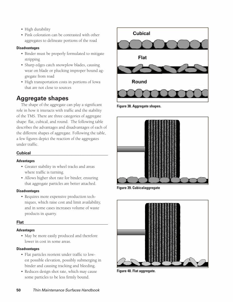
50 Thin Maintenance Surfaces Handbook
High durability• Pink coloration can be contrasted with other • aggregates to delineate portions of the road
DisadvantagesBinder must be properly formulated to mitigate • strippingSharp edges catch snowplow blades, causing • wear on blade or plucking improper bound ag-gregate from roadHigh transportation costs in portions of Iowa • that are not close to sources
Aggregate shapesThe shape of the aggregate can play a signifi cant
role in how it interacts with traffi c and the stability of the TMS. There are three categories of aggregate shape: fl at, cubical, and round. The following table describes the advantages and disadvantages of each of the different shapes of aggregate. Following the table, a few fi gures depict the reaction of the aggregates under traffi c.
Cubical________________________________________Advantages
Greater stability in wheel tracks and areas • where traffi c is turning. Allows higher shot rate for binder, ensuring • that aggregate particles are better attached.
DisadvantagesRequires more expensive production tech-• niques, which raise cost and limit availability, and in some cases increases volume of waste products in quarry.
Flat________________________________________Advantages
May be more easily produced and therefore • lower in cost in some areas.
DisadvantagesFlat particles reorient under traffi c to low-• est possible elevation, possibly submerging in binder and causing tracking and bleeding.Reduces design shot rate, which may cause • some particles to be less fi rmly bound.
Figure 38. Aggregate shapes.
Figure 39. Cubicalaggregate
Figure 40. Flat aggregate.
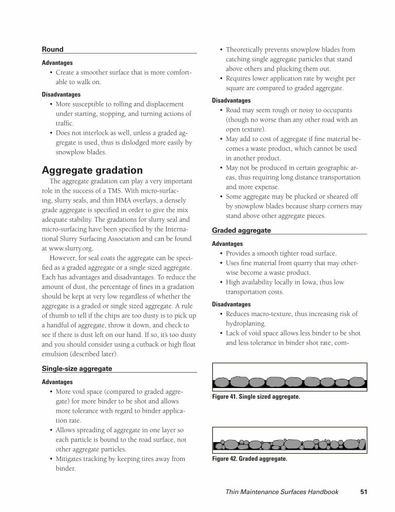
Thin Maintenance Surfaces Handbook 51
Round________________________________________Advantages
Create a smoother surface that is more comfort-• able to walk on.
DisadvantagesMore susceptible to rolling and displacement • under starting, stopping, and turning actions of traffi c.Does not interlock as well, unless a graded ag-• gregate is used, thus is dislodged more easily by snowplow blades.
Aggregate gradationThe aggregate gradation can play a very important
role in the success of a TMS. With micro-surfac-ing, slurry seals, and thin HMA overlays, a densely grade aggregate is specifi ed in order to give the mix adequate stability. The gradations for slurry seal and micro-surfacing have been specifi ed by the Interna-tional Slurry Surfacing Association and can be found at www.slurry.org.
However, for seal coats the aggregate can be speci-fi ed as a graded aggregate or a single sized aggregate. Each has advantages and disadvantages. To reduce the amount of dust, the percentage of fi nes in a gradation should be kept at very low regardless of whether the aggregate is a graded or single sized aggregate. A rule of thumb to tell if the chips are too dusty is to pick up a handful of aggregate, throw it down, and check to see if there is dust left on our hand. If so, it’s too dusty and you should consider using a cutback or high fl oat emulsion (described later).
Single-size aggregate________________________________________Advantages
More void space (compared to graded aggre-• gate) for more binder to be shot and allows more tolerance with regard to binder applica-tion rate.Allows spreading of aggregate in one layer so • each particle is bound to the road surface, not other aggregate particles.Mitigates tracking by keeping tires away from • binder.
Theoretically prevents snowplow blades from • catching single aggregate particles that stand above others and plucking them out.Requires lower application rate by weight per • square are compared to graded aggregate.
DisadvantagesRoad may seem rough or noisy to occupants • (though no worse than any other road with an open texture).May add to cost of aggregate if fi ne material be-• comes a waste product, which cannot be used in another product.May not be produced in certain geographic ar-• eas, thus requiring long distance transportation and more expense.Some aggregate may be plucked or sheared off • by snowplow blades because sharp corners may stand above other aggregate pieces.
Graded aggregate________________________________________Advantages
Provides a smooth tighter road surface.• Uses fi ne material from quarry that may other-• wise become a waste product.High availability locally in Iowa, thus low • transportation costs.
DisadvantagesReduces macro-texture, thus increasing risk of • hydroplaning.Lack of void space allows less binder to be shot • and less tolerance in binder shot rate, com-
Figure 41. Single sized aggregate.
Figure 42. Graded aggregate.
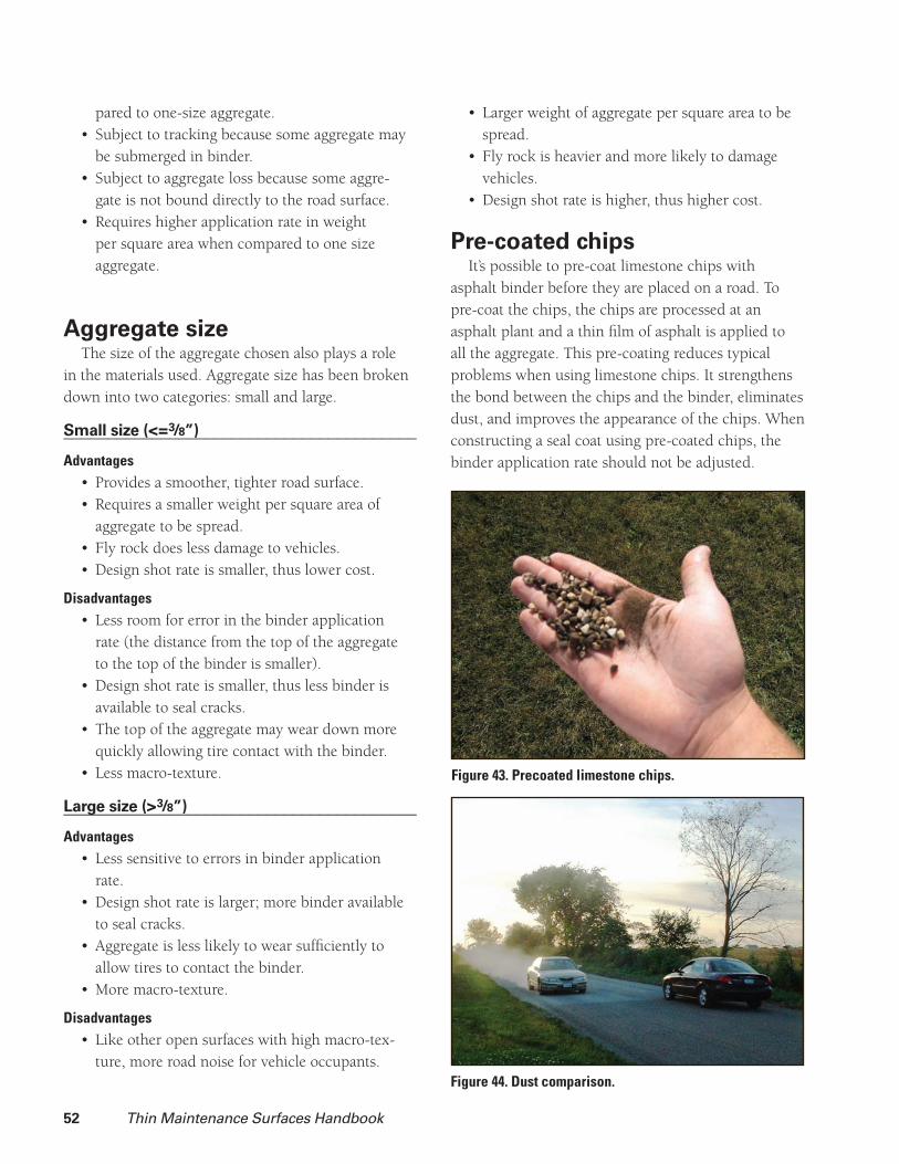
52 Thin Maintenance Surfaces Handbook
pared to one-size aggregate.Subject to tracking because some aggregate may • be submerged in binder.Subject to aggregate loss because some aggre-• gate is not bound directly to the road surface.Requires higher application rate in weight • per square area when compared to one size aggregate.
Aggregate sizeThe size of the aggregate chosen also plays a role
in the materials used. Aggregate size has been broken down into two categories: small and large.
Small size (< = 3/8”)________________________________________Advantages
Provides a smoother, tighter road surface.• Requires a smaller weight per square area of • aggregate to be spread.Fly rock does less damage to vehicles.• Design shot rate is smaller, thus lower cost.•
DisadvantagesLess room for error in the binder application • rate (the distance from the top of the aggregate to the top of the binder is smaller).Design shot rate is smaller, thus less binder is • available to seal cracks.The top of the aggregate may wear down more • quickly allowing tire contact with the binder.Less macro-texture.•
Large size (> 3/8”)________________________________________Advantages
Less sensitive to errors in binder application • rate.Design shot rate is larger; more binder available • to seal cracks.Aggregate is less likely to wear suffi ciently to • allow tires to contact the binder.More macro-texture.•
DisadvantagesLike other open surfaces with high macro-tex-• ture, more road noise for vehicle occupants.
Larger weight of aggregate per square area to be • spread.Fly rock is heavier and more likely to damage • vehicles.Design shot rate is higher, thus higher cost.•
Pre-coated chipsIt’s possible to pre-coat limestone chips with
asphalt binder before they are placed on a road. To pre-coat the chips, the chips are processed at an asphalt plant and a thin fi lm of asphalt is applied to all the aggregate. This pre-coating reduces typical problems when using limestone chips. It strengthens the bond between the chips and the binder, eliminates dust, and improves the appearance of the chips. When constructing a seal coat using pre-coated chips, the binder application rate should not be adjusted.
Figure 43. Precoated limestone chips.
Figure 44. Dust comparison.

Thin Maintenance Surfaces Handbook 53
BinderThere are three different types of binders that can
be used for TMS: cutback, emulsion, and hot asphalt binder. Only cutbacks and emulsions are commonly used in Iowa.
A cutback is an asphalt binder that has been lique-fi ed for low temperature use by the addition of a cutter, typically a petroleum product such as kerosene or fuel oil. Cutbacks can be used later in the season because the curing process only involves the evapora-tion of the cutter. Cutbacks stay active longer, which means that they are able to penetrate and coat the dust that may be on the aggregate. Cutbacks also have a much higher percentage of binder which leads to more asphalt being left on the road surface per gallon of binder applied when compared to an emulsion.
An emulsion is a mixture of asphalt binder, water, and an emulsifying soap. It’s created by grinding the asphalt binder into microscopic globules and mixing it with water and the soap. The soap prevents the globules from clumping together. This suspends them in the water. Depending on the type of surfactant used, it’s possible to change the charge of the emul-sion in order to improve the bond with the aggregate. In Iowa, cationic (positively charged) emulsions are used because most aggregate is negatively charged. When the emulsion is placed on the pavement, the soap is attracted to the aggregate leaving the asphalt particles behind to group together, forming an asphalt
Figure 45. Three different types of binders.
skin on the aggregate. This process is called breaking and can be identifi ed when the color of the emulsion turns from brown to black. After the emulsion has broken, the water begins to evaporate out of the emul-sion—this is curing.
When selecting a binder, consider the aggregate too. The ability of the binder to bind to the aggregate is largely dependent on the aggregate’s properties. For example, if the aggregate is dusty, some binders will bond with the dust and not the aggregate, which results in the aggregate raveling off due to the poor bond.
The following binders are commonly used in Iowa.
Cutback asphalt________________________________________Advantages
Best at binding dusty aggregate.• Some possible penetration into dry road sur-• faces increases bond.Will retain aggregate that is not spread immedi-• ately after shooting binder.
DisadvantagesSubject to bleeding and tracking.• Some products are fl ammable.• Emits hydrocarbons during curing process.• Curing can take considerable time.• Aggregates must be dry.•
Cationic rapid setting (CRS)________________________________________Advantages
Binds clean aggregates with low clay content • securely to road surface.Cures quickly.• Works with damp aggregate.• Commonly available and familiar to industry • participants.
DisadvantagesIneffective for dusty aggregates or aggregates • with high clay content.Aggregate must be spread immediately behind • distributor truck.
High fl oat________________________________________Advantages
Binds aggregate with more dust and clay when •
54 Thin Maintenance Surfaces Handbook
compared to CRS.Cures quickly, but not as quickly as CRS.• Works with damp aggregate.• May coat aggregate more thickly, yet reduce • movement that causes bleeding due to “gel” structure of cured emulsion.
DisadvantagesDoes not cure as quickly as CRS (but more • quickly than cutback).Industry participants may not be as familiar • with this product as CRS, depending on geog-raphy and local experience.Some hydrocarbons released during curing due • to the use of cutter (kerosene) in this product (much less than standard cutback).
Polymer-modifi ed
(added either to CRS or high fl oat)________________________________________Advantages
Greater fl exibility during cold weather, miti-• gates cracking.
Greater stiffness in warm weather, mitigates • bleeding and retains aggregate in areas of turn-ing, accelerating, and decelerating traffi c.Higher early strength during curing leads to • better chip retention.
DisadvantagesHigher cost compared to non-polymer-modi-• fi ed binder.
Design methodsIt’s possible to calculate the ideal application rates
of both the aggregate and binder. The Minnesota DOT Seal Coat handbook contains a good design method. The aggregate application rate depends on the aggre-gate gradation, shape, and specifi c gravity. The binder application rates depend on the aggregate gradation, absorption, shape, traffi c volume, existing pavement condition, and the residual asphalt content of the binder.
Specifi cation references:

Thin Maintenance Surfaces Handbook 55
Selecting the best contracting method and speci-fi cation can help an agency receive the best surface for the dollar. There are several types of contracting techniques that are used to place all of the risk on the contractor or agency and others that distribute the risk among the involved parties. However, if the agency owns its own equipment and does all the work in-house, it isn’t necessary to develop a contracting method.
When deciding on the type of contract to be used, the agency must decide how much risk it’s willing to bear. Each type of contract, specifi cation, or warranty allocates the risk between the agency and the contrac-tor in a different way. If the agency places the entire burden on the contractor, it will likely pay a premium for shedding the risk. On the other hand, if the agency takes all the risk, the contractor may be unmotivated to avoid risk on the agency’s behalf.
Three typical types of contracts are let for thin maintenance surfaces: lump sum contract, a unit price for the area, and a unit price for the material. All have advantages and disadvantages.
Lump sumIn a lump sum contract, the contractor provides
the agency with one price that includes materials, labor, mobilization, overhead, and profi t. Lump sum projects can be risky for a contractor if more material is used than initially estimated because the extra cost of that material is absorbed by the contractor. Conse-quently, contractors are more likely to raise the total price of a contract to allow for contingency funds. They may also decide to save money by decreasing the amount of materials used to cut the risk of material overruns. This can result in a low quality surface.
Unit price for areaIn a unit price for area contract, the agency pays
a set amount per unit of area covered. This provides fl exibility in case the agency wishes to add or subtract work from the contract. The adjustment is made by
Ch 9. Contracting
simply paying for more or fewer units. If mobilization is paid as a separate item, the contractor does not have to “bury” that expense in the unit price for area, and the agency may be able to add additional work for less cost than if mobilization were not a separate item. However, with this method, the contractor’s prof-its will increase if it uses less material. Agencies are sometimes concerned that insuffi cient material will be placed unless they are vigilant about the application rates. In most cases, contractors are concerned about agency satisfaction, so this is not an issue.
Unit price for materialsIn a unit price for materials contract, the agency
pays for each gallon of binder and each ton of aggre-gate used. This eliminates the incentive to skimp on materials. However, some vigilance is sometimes required to ensure that contractors do not waste materials. This tendency can be reduced if the agency and the contractor agree on a standard application rate after a few test applications are made to fi nd the appropriate rate for the job’s conditions. The fi nal cost of the contract is more unpredictable compared to other methods since required application rates may vary according to project conditions. On the average, this method should result in the lowest overall cost because the contractor has to make up the smallest amount to cover risk.
WarrantiesIf the contractor is given some latitude with regard
to material selection and construction methods, a war-ranty can be included in the specifi cation. One-year warranties are sometimes used for thin maintenance surface construction. In general, if the surface is performing well at the end of a year, it will usually perform satisfactorily for its expected life. Note that the warranty should not include items that are beyond the scope of thin maintenance surface capabilities such as correcting structural failures or withstanding aggressive snow plowing.

56 Thin Maintenance Surfaces Handbook
Construction seasonWhen constructing a new surface on a pavement,
it’s best to place the surface in the hottest and driest weather possible. Hot and dry weather helps the water in an emulsion or the cutters in a cutback evaporate quickly which speeds up the curing process. Also, avoid placing a TMS when the project is threatened with rain or cold weather.
It should be stated in a contract that the construc-tion should be completed before a specifi ed date to ensure that the surface is not constructed too late in the season. Additionally, the specifi cations should state that the construction should not take place if there is a threat of rain.
If an agency has its own crews, the maintenance department should have a policy that states that all surfacing should be performed by a specifi c date. A common last day in Iowa is August 15th. This allows time for crews to fi nish work and stripe the pavements before school starts.
Many times it’s advantageous to perform mainte-nance such as crack sealing or patching well before the construction of the surface in order for the crack sealing material to cure or the patch to compact under traffi c. If the agency wants to ensure that surface construction takes place after these other maintenance activities, this should be noted in the specifi cations or maintenance policy.

Thin Maintenance Surfaces Handbook 57
Traffi c controlTraffi c control is a vital part of all TMS construc-
tion. The main purpose of traffi c control is to protect construction workers. It also prevents collisions between road users and construction equipment. The traffi c control set up should direct traffi c through the work zone and past hazards that the construction presents. Motorists should easily understand the traf-fi c control set up.
Consult the Manual on Uniform Traffi c Control Devices (MUTCD), Chapter 6H for proper tech-niques and sign placements. Published by the Federal Highway Administration, this manual is available at http://mutcd.fhwa.dot.gov/pdfs/2003r1/pdf-index.htm.
Quality controlThe right treatment and the best materials cannot
overcome poor construction. Proper construction pro-cesses must be followed. Quality control is the process of ensuring that the construction plans, agency poli-cies, and contract specifi cations are being followed. This process ensures that a satisfactory product has been constructed and the likelihood of a successful, long-lasting surface is increased.
Quality control should start before the actual application begins. This includes ensuring that all necessary equipment and materials are on site before construction begins, the pavement has been cleaned, and any necessary maintenance such as crack sealing has been previously performed.
Quality control should also involve making sure that the equipment is in proper working order. The spray bar should be set at the right height. The spray nozzles should be clean and properly aligned. All of the gates should in proper working order on a chip spreader. The equipment manuals should contain a checklist that describes a pre-construction inspection. It’s wise to check on a regular basis items such as these that could hinder the construction.
Ch 10. Construction
Quality control also ensures that proper techniques are being followed during construction and making sure that any re-work is promptly performed. During construction make sure that all joints are straight and clean and that areas with an inadequate amount of aggregate receive a second pass by the chip spreader (a light application) or a few shovels full of aggre-gate are spread to prevent bleeding. It’s important to ensure that the binder has not set before the aggregate is placed.
The crew applying the surface has the greatest ability to perform the quality control function. Crew members have direct control over the process and are in the best position to know what’s being done well and what’s being done poorly. They also can watch one another’s work and communicate whether a change needs to be made. This responsibility for quality control should be communicated to the crew members and their responsibilities should be properly defi ned.
Following is a list of a seal coat crew members’ jobs and their quality control activities:
Distributor truck drivers Before starting, they should make sure that
Traffi c control is in place. • Aggregate is on site.• Their distributor truck is functioning properly • with all of the nozzles properly aligned and cleaned and the spray bar at the right height. Pavement has been swept.• Necessary equipment such as the chip spreader • (with aggregate truck attached) and rollers are on site and prepared to begin construction.
During construction drivers shouldMaintain a proper distance in front of the chip • spreader and slow down if the chip spreader is not keeping up.Be aware of the amount of emulsion left in the • tank.

58 Thin Maintenance Surfaces Handbook
Chip spreader operators Before starting, they should make sure that
Gates are properly opened and aligned.• Belts and feeds are functioning properly.•
During construction operators shouldMaintain communication with the distributor • truck operator. Tell the distributor truck operator when to stop • because the chip spreader is running out of aggregate. This will prevent the chip spreader from running out of chips and prevent the binder from sitting too long without being covered. Watch the distributor truck’s application to • make sure it’s consistent and there are no streaks (caused by plugged or poorly aligned nozzles or incorrect spray bar height). Let the driver know if more or less binder should be applied.
Pneumatic tire roller operators Before starting, they should make sure that the tires are at the specifi ed air pressure.
During construction roller operators shouldWatch the chip spreader’s application to make • sure the proper amount of chips is applied and that they’re evenly spread over the pavement.Make sure the chip spreader isn’t changing • directions too quickly, causing the aggregate to come unbound from the binder.
Quality control should also be performed by an inspector, the foreman of an in-house construction crew, or the street superintendent to ensure that the fi nal product is of good quality and that no rework should be performed.
A series of pamphlets called “Pavement Preserva-tion Checklist Series,” developed by the Foundation for Pavement Preservation and the Federal Highway Administration, provide useful information on the construction of crack sealing, seal coating, slurry seal/micro-surfacing, and thin HMA overlays. These pamphlets also defi ne various quality control tech-niques for all types of surfaces and have a checklist of
items that can be used for quality control purposes. These checklists can also be used to defi ne the quality control roles of the various workers on a crew.
Construction planA construction plan is essential for the success
of a TMS—it’s the fi rst form of quality control on the project. The team that develops the construc-tion plan should include the engineer, maintenance superintendents, and maintenance foreman. The plan should ensure that traffi c control signs and barriers are delivered and set up, all equipment is brought to the site on time and in good working condition, and all materials are delivered on time or that the neces-sary trucks have been reserved to deliver the materials during construction.
Although a specifi c plan is not necessary for each project, it’s advantageous to develop one for each type of surface such as a seal coat or a slurry seal. The plan may be a short checklist of items. Specifi c plans for individual projects may consist of scheduling the work, ensuring that all equipment and materials are available or ordered, and traffi c control rental or setup has been ordered.
The previously mentioned “Pavement Preservation Checklist Series” provide helpful insight when devel-oping construction plans.
DocumentationAgencies should keep detailed documentation of
the surfaces applied to roads. This should include application rates of the binder and aggregate, material types, costs, and any other information that might be useful in the future such as a brief description of the work performed or any problems that were encoun-tered. This documentation is useful when looking back to discover which surfaces were successful or unsuccessful. It also helps to know what lies beneath the surface when reconstruction or rehabilitation is going to be performed. Individual agencies should develop a documentation process that’s consistent with other documentation they’ve developed.


Center for Transportation Research and Education
Iowa State University
2711 South Loop Drive, Suite 4700Ames, IA 50010-8664Phone: 515-294-8103
Fax: 515-294-0467www.ctre.iastate.edu