this document has been reproduced from microfiche ...€¦ · in addition, control will cv~ntual1y...
TRANSCRIPT

N O T I C E
THIS DOCUMENT HAS BEEN REPRODUCED FROM MICROFICHE. ALTHOUGH IT IS RECOGNIZED THAT
CERTAIN PORTIONS ARE ILLEGIBLE, IT IS BEING RELEASED IN THE INTEREST OF MAKING AVAILABLE AS MUCH
INFORMATION AS POSSIBLE
https://ntrs.nasa.gov/search.jsp?R=19820009379 2020-07-09T19:53:53+00:00Z

r"C-~''''''''''"h:)i , . -, , , ,
; lin ie ,g Pi'
,IPL PUBLICATION 81-104
(H1SA-Ct-168_30) SAflLLITI AffLICATIGIS TO H82-17~53 BLECTRIC-UTILITI coalUMICAIICIS lilts CJet Propul~ioD Lab.) 111 p tiC A06/1r A01
I.
CSCt 178 Uaclas G3.117 08S15
SateUite Applications to Electric-Utility Communications t leeds M. Horstein R. Barnett
December 1, 1981
National Armnautics and Space Administration
Jet Propulsion laboratory California Institute of Technology Pasadena, California

JPL PU BLiCATION 81· 104
Satellite Applications to Electric-Utility Communications Needs M. Horstein R. Barnett
December 1, 1981
National!- ',onautics and Space Administration
Jet propulsion Laboratory California Institute of Technolo'IY Pasadena, California

I
~
The research described in this publication was carried out by the Jet Propulsion Laboratory, California Institute of TechnOlogy, und/!r contract with the National Aeronautics and Space Administration.
~ --"-.~"- .... ---,-... ~ ....... ,.,~ .....

ABSTRACT
Sianificant chan.e. in the Nation'. electric power .y.tem. are expected to re.ult from the inte.ration of new technolo.y, po •• ibly durinl the next decade. Di.ital communication. for monitor and control, exclu.iye of protectiYe relayinl, are e.pected to double or triple current traffic. !.timat •• of thi. traffic haye been made and a n.tionwide e.timata of 13 Mb/. ha. been projected. Of thi. total~ 8 Mb/. i. attributed to the bulk-power .y.tem a. it i. now beinl operated (4 Mb/.) and a complex of the larler-.i.ed di.per.ed 'tor~,a and .eneration unit. (4 Mb/.). Thi. traffic could be accommodated by current communication •• atallite. u.in, 3- to 4.5-m-diametar ,round terminal. co.tin, $35,000 to $70,000 each. The remainin, 5-Mb/. traffic i. attributed to new technolo,y concept. inte8rated into the di.tribution .y.tem. Such traffic i. not compatible with current .atellite technolo,y becau.e it will require .mall, low-co.t ,round urminall. Therefore, a hi,h effectiye ilotroJlic radiated power .atellite •• uch a. the one bein, planned by NASA for the Land Mobile Satellite Service, will be required. A new frequency allocation for the utility', fixed .eryice may al.o be de.irable. Inclu.ion of other el.ctricutility operation.-related function. could .igniflcantly increa.e thi. trafficl n.yerth.l •••• a .hared .eryice with other u.er. may be deeirable to proyide an .fficient ,atellit. workload.
Hi
,

!r""~$"~ 'C'~
~
ACltHOWLEDGMENT
Thi •• tudy wa. conducted by the Jet Propul.ion Laboratory under the .ponaor.hip of the Office of Space and Terreatrial Application. of thd National Aeronautic. and Space A~ini.tration, and waa a~iniatered by Mr. Jerose Preibaua. Support to the .tudy wa. provided by the J~t Propul.ion Laboratory'. Ca.munication. and Control for Electric Power Sy.t .. a ~roject throulh the Office of Electric In,rlY Sy.t ... of the U.S. Depart.ent of InerlY, and wa. arranled by Mr. Phillip Overholt.
iv
1 ! ~
~ 'I .~
~ A }
~ .~~
.~ , ,~
~""""_'"<''' :..:,.,~ ... ,:,~,~,."_",_._""",;",_,,,.,,~~£VCcy .. n'.brikaWdSHirlf."':eI'ftt7 r._ ~~ ... P~ ,,~~.;~~.,",. t." . ,,,,*, ... ___ " ,~~, ,_ .. " ••• "'" .............. .., ...... ~" ... _'-.-" ---•• "" • ~_j

ACE
AGe '\ ANSI
~ AT8
BER
BPS
BSS
CATV
CCIR
CII
CIIM
C/N
CONUS
DAC
DCS
DOC
DOE
DSG
ECC
EOO
EIRP
EMS
Rb/No
I EPRI ,
~ FCC
FDNA
FDM/FM
FSK
FSS
GOSS
CIT
HPA
AlBRlVlATION8 AND ACRONYMS
area control error
auta.atic ,eneration control
Aaerican National Standard. In.titute
Advanc6d Te~hnolo,y Satellite
bit error rate
bulk-power .ub.tation
broadca.t-~atellite .ervice
~able televi.ion
International aadio ~on.ult.tive Committee
carrier-to-interference ratio
carrier-to-intermodulation ratio
carrier-to-noi.e ratio
Continental United Statel
distribution automation ahd coatl"ol
de.ignated control Itation
diltribution dilpatch c~"~er
Department of Energy
dilpereed .torMge and 8eneratio~
energy control center
economic di.patch control
effective ieotropic radiated power
energy-management .ystem
energy per bit-to-noise power density ratio
Electric Power Reeearch Institute
Federal Communication8 Commi88ion
frequency-divi8ion mUltiple acceee
frequency-divilion multiplexlfrequency modUlation
frequency-.hift-keyed (modulation)
fixed-.atellite 8ervice
Geostationary Orbiting Experimental Satellite
receive antenna gain/receive-.Y8tem noiee temperature high-power amplifier
v

lED
LDC
LFC
NASA
NOAA
PAX
PFO
PLC
PSK
PURPA
RTU
SCADA
SCPc
TDMA
TWT
UHF
VAR
VHF
WARC
ABI.RlVlATIONS AND ACRONYMS (Cont'd)
In.tltute of Electrical and Electronic. Enalneer.
load-dl.patchlna center
load frequency center
National A.ronautlc. and Space Ad.lnl.tration
National Oceanic and At.o.pherlc Ad.lnhtraUon. private l,utoaatiC e.chanae
pow~r fl~x den.ity
power-line carrier
pha.e-.hift-keyed (modulation)
Public Utility Regulatory Policy Act
remote tel'lli ual unft
supervi.ory control and data acqui.ition
aingle channel per carrier
time-division multiple access
traveling wave tube
ultra-high frequency
volt-amperes reactive very-high frequency
World Administrative Radio Conference
vi
l ., j
! .~
J

. ~ $ % R
CONTENTS
PART ONE
EXECUTIVE SUMMAllY • • • • • • • • • • • • • • • • • • • • • • • • • •• 1 ~ -
I
~. PART TWO
SATELLITE APPI.ICATlONS TO ELECTRIC-UTILITY ,,'C)HHUNIC4TIONS NEEDS
1. INTRODUCTION • • • • • • • • • • • • • • • • • • • • • • • • • •• 1--1
II. ELECTRIC-UTILITY CONTROL-SYSTEM MODEL . . . . . . . . . . . . . . 2-1
Ill. BULK-POWER-SYSTEM TRAFvIC REQUIREMENTS · . . . . . . . . . 3-1
A. MONITOR AND CONTROL FUNCTIONS · . . . . . . . . . . . 3-1
B. UTILITY EXAMPLE . . . . . . . . . . . . . . . . . . . . . . 3-3
1. Shortcomings of Present Control System •••••••• 3-3
2. Future SCADA System • • , • • • • • • • • 3-4
3. Traffic Estimate Based on Bulk-Power-System Requi rements • • • . • • • • • • • • • • • • • 3-4
C. TRAFFIC ESTIMATE BASED ON JPL ELECTRIC-UTILI'1'Y MODEL • 3-9
IV. DISPERSED STORAGE AND GENERATION TRAFFIC REQUIREMENTS 4-1
A. DSG COMMAND AND CONTROL FUNCTIONS · · · · . . . . 4-1
B. DSG COMMUNICATIONS TOPOJ.oGY · · · · · · . . 4-2
C. TRANSMISSION PROTOCOLS • · . · · · · · • · · · · 4-4
D. SINGLE-DSG DATA RATE • . · · · · · · • · · · 4-9
E. SINGLE-UTILITY DATA RATE · · · · · · · · · 4-9
F. SYSTEM TRAFFIC ESTIMATE · . · · • · · · · · · · 4-10
vii

OONTENTS CCont'd)
V. DISTRIBUTION-SYSTEM TRAFFIC REQUIREMENTS · • · · · · 5-1 A. LOAD-MANAGEMENT FUNCTIONS
~-l
B. OPERATIONAL-MANAGEMENT FUNCTIONS · · • · · · . 5-2 I
~ C. MITRE 't'RAFFlC ESTIMATE . · · · · · · • . 5-3 D. BOEING TRAFFIC ESTIMATE · · · · · • · · · · . 5-4 E. JPL TRAFFIC ESTIMATE . . . . . · · · · · . . 5-5
VI. THE ROLE OF SATELLITES IN UTILITY CONTROL-SYSTEM COMMUNICATIONS 6-1 A. ALLOCATED FREQUENCY BANDS AND AVAILABLE SATELLITES · · 6-2 B. St'ITABILITY OF SATELLI'&r. COMMUNICATIONS · · · · . · · 6-6
1. Bulk-Power System . . · . . . . · · · · · . · · . 6-7 2. Dispersed Storage and Generation · · · · · 6-10 3. Distribution System . · . . . · · · · · · . · · 6-11
C. DISTRIBUTION-SYSTEM COMMUNICATION ALTERNATIVES 6-17 1 1. VHF or I1HF Radio
6-18 ! . . . · · • ·
I 2. Power-Line Carrier . · · · · 6-19 3. Telephone · · · · · · · · · · 6-20 j
! l 4. Cable Television . · · · · · · · · · · 6-21 ~
i 5. SUI1l1Iary . . . . . . · · · · · . . . 6-21 I ~ ~ D. SUHHAR'l
6-21 , . . . . . . . · · · · · · · · , ,1 ~ , ~ VII. TRANSPONDER MULTIPI.E ACCESS · · . · · · · · · · 7-1
A. TRANSPONDER CHANNELI~ATION AND NODE ASSIGNMENT 7-1 ~ ~ B. TIME-DIVISION MULTIPLE-ACCESS FORMAT
7-2 1 · · · · J ,l C. SLOT ASSIGNMENT AND TIMING CONSIDERATIONS · · . . · · · 7-3 i~
D. HALF-DUPLEX OPERATION . . . · · · · · · · · · . . 7-6
viii

---_""" -"""-'~ ......... ,""'-..-..ot!!i1I ................. ; __ • _____ I_~~,_ .. ___ ._._._U_. ______ ---il,.cJ....:.~,,·· - ":~~_.:; .. __ ~~:"", ___ .. _
CONTENTS (Cont'd)
VIII. USE or CUlRENT C-IAND SATELLITES • . • • • • • • • • • • • • • • • 8-1
A. DOWNLINJ' CONSIDERATIONS • • • • • • • • • • • • • • • • • • 8-2
I. UPLINK CONSIDERATIONS . . . . · . . . . . . . . . 8-6
C. CHANNEL DA'l'A RATE • • • • • • • • • • • • • • • • • • • • • 8-8
D. INTERPF.RENCE WITH OTHER SATELLITE SYSTEMS . . . . . . . 8-10
E. EARTH-STATION PR!CES • • • • • • • • • · . . . . . . . ~ . 8-13
IX. CONCLUSIONS AND RECOMMENDATIONS . . . . . . . . . . . . . . . . . 9-1
X. REFERENCES............................ 10-1
APPEND IX • • • • • • • • . • • • • • • • • • • • • • • • • • • • • • • • A- 1.
Figures
2-1. Mlljor Components of an Electric Power Syfttem • 2-2
2-2. Typical Utility Control-System Structure •• . . . . . . 2-4
2-3. Puture Control System Incorporating Distribution Automation and Control • • • • • • •• • • 2-6
3-1. Telecommunications Channel Network • • 3-5
3-2. Poll/Respon.e Mes.age Pormats 3-7
3-3. Energy Control Center Data-Flow Diagram · . . . . . . . . . 3-11
4-1. Time-Division Multiple-Access 'rame Format 4-5
4-2. Message Formats for LFC and SCADA Transactions . . 4-7
4-3. Message Establishment Field 4-8
4-4. Channel Cllpacity Requirements
7-1. Time-Division Multiple-Access Frame Format . . . . . . . 7-4
7-2. Half-Dvplex Time-Division Multinle-Access Format 7-7
8-1. Earth-Station Transmitter Requirements with l-m Antenna . . . . . . . . . . . . . . . . . . . . . . . . . . 8-9
ix

r' ~---,...--• .--=
CONTENTS (Cont'd)
Tabl ..
2-1. Functional Cla •• ific&t;on of Oi.tribution-Sy.ta. Componen t • • • • • • • • • • • • • • • • • • • • • • • • •• 2 - 3
~ I
3-1. Pullina Rate. for Data Acqui.ition • • • • • • • • • • • •• 3-8
J-2. Salient Feature. of Synthetic Utility •••••• 3-10
3-3. Synthetic-Utility Bulk-Power-Sy.tea Data Requirement. (kb /. ) • • • • . • • • • • • • • • • • • • • • • • • • • 3-10
4 . - . Required Me .. age I.enath. (bit.) for Single Tran .. ction • 4-9
5- • Di.tribution-Sy~tem Element Population • · . . . 5-6
5-2. Operational'·Management Evt:.lt Frequency •• . . . . . . . . . 5-6
5-3. Communication. Traffic, We.tern Region: 1995 5-7
5-4. Di"';,ib·'tion-Syatem Monitoring Point. • •• 5-8
6-1. Fixed-S4tullite Servi~e Allocation. Below 35 GHz: 1979 WARC • • • • • • • • • • • • ••• · . . . 6-3
6-2. S-Band Downlink for Operation at the PFD Limit · . . . 6-14
6-3. Feasible Communication "edia for Performing DAC Function ••• 6-22
6-4. Factors Affecting Applicability of Satellite Commuhlcations 6-~4
8-1. Representative (4 GHz) Downlink for Westar Satellite • 8-3
8-2. Representative (6 GHz) Uplink for Westar Satellite. · . . . 8-7
8-3. Earth-Station Price Estimates ($K) ••• . . . . . . 8-13
x

PART 0IfI
IXICUTIYI SUMMARY

I
~
EXECUTIVE S~IY
SATELLITE APPLICATIONS TO ELICTIIC-UTILITY COMMUNICATIONS NEEDS
Thl. "utly ..... th • ."lIc«1l11ry of .. ,.111,., to th. communle.tlont f!qul,.",.,.". for monitor Md control of -'«trlc utili, •. T"- cur,.", n.,IonwicJ. bullc·poWfl,.,y""" monitor Md control tr."1e " .tlm.t«J ilt 4 Mbll. It I, furth., .,Im.t«J th.t by th • .,.., 2(J()() m. I""., II,. of d...,. ,to,.,. ."d ,.".,.,Ion unl" will cont,lbu" 4 Mbll of MldltloMl "."Ie. Both of th* fIfIfIdI .. m .",.,,«1'- to, ~,.,d c." ". .. tie· fl«l by, cu,,.,,t communle.,/onJ .,.,,,,... In cont,.t, futu,. monltrl ."d control t,.mc, .tlm.r.d ., .bout 6 Mbll, ,r.mmlng from In,..tlon of MW t.'I:,molow Inlo til. dl",Ibulioo ,y,'.m I. not com".tlb'- with cu',.", .,."'", tflChnolog,.. Nft<v .. ,. Mil,.. .,. ~ulml which ".""It m. CM of """/, IoW<Olt ground ,.,mlnM,. ,.". .t· Milt. pl."MtJ by NASA fo, th. L~ Mobil. SII"'''t. s.rv~ I, • good .ItMnP'-. Om., opM4tlon,.,.,.r.d futtetlo'lM ~ul,.",."" th.t ... m to M co",,,.,Ibl. with "~,. cu,,.,,t or pl."Md .. ,./Ilt. t«hnolow, " th. L .. -.d Mobil. SIIt.lllt. SIIrvlc. i, included, .,.: (t) vo~ ."d d.t. communlc.tiont to v.,lou, o~r.tlon.' ,1,." mobil. unilJ, ,,,.In,''''.nc.lNrvlc. CMl"", ."d M1g/~'lng/Hm;nllt'.tI",'oc.t'on', .nd (2) ~o,. vidtlo m;Jflltorin, .nd ,.'«onf.,.ncin" fo, which n-.el, .,. MI,."ln, or inc",.,l"g. ,.".. function, would ."""Ic.,,tly Inc,... th. po,.ntl., .. ,./11,. t,.mc _ifl/,MJI. to tM .I«trlc utllltl ...
Many electric utilitie. are In the proce •• of upgrading their control .y.te •• to provide more compreh4n.lv~ and automate~ control of bulk-power.y.tem functions. In addition, control will cv~ntual1y be extended to the dl.tribution .y.tem for operatlonal- and 10ad-managem4ut purpo.e.. Thl. development will be accompanied by, and perhapa ha.tened by, the need for control of dl.per.ed .torage and generation (DSG) unit. located In the dl.trlbution ayatem. All of the.e control proc~.ae. will involve the development ~f reliatlle coamunlcation .y.tems of suitabI.! capacity. The purpo.e of thf. r@port i. to explorft way. In which the.e communication. might be provided by .ne11ite tran.ml .. lon.
A aatell1te syatem .erving bulk-power-.y.tem needs could be e.tabli.hed through the lea.e of capacity on one of the current C-band commercial satellites. It is estimated that the total bulk-power control-.y.tem traffic of a large utility (i.e., one aupplyins 1% of the nation'. electrical energy) i. about 40 kb/.. With current tariffs, the annual coat of leaft1ng backed-up tran.ponder capacity to accommo~ate thia traffic is about *10,000. Because of the small point-to-point traffic on most ~ulk-power-system link., each satell1t.e channel ~ould most probably be operated in a time-division-multlpleacce .. (TDNA) mode, with the .:hannel bandwidth choaen to accommodate the total 'Julk-power-8y.tem traffic of a Bingle utility.
The price of a fully redundant, 4.5-meter, TDNA earth station designed for this application 1. estimated to be *74,000. Incorporation of redundancy into the earth-station design ~~rtually eliminates the possibility of an /jutage due to COlDponelnt failure in the ground segment. In the event of a tran.ponder failure, the presence of an alternate communications mode ma~~8 possible an almost in.tantaneous .witchover to the backup transponder. A significant communication. outage, lasting several hours, would occur only as the result of a total satellite failure. In this event, th~ alternate communication. mode would be used until the earth-station antennas could be repointed in the direction of the backup sa~ellite.
I

C-band satellite communication. could al.o be u.ed in the ~ontrol of DSG8. The8e renewable 80urce. of energy are expected to contribute betv~en 4% and 10% of the nation'. electrical energy .upply by the year 2000. C-band transmiS8ion i& an ideal form of ~ommunications for th08e typeD of DSG8 (e.g., hydroelectric and wind-generation) located in remote areas, where location and/or terrain make other communication8 alternative. unattractive.
On the other hand, satellite transmission at C-band may be inappropriate for DSG. located i" lAure populous areal, becaule of the need for coordination with terrestrial .ervic~1 operating in the same frequency band. Sate]~ite transm1ss •. on at Ku-band wuuld solve thi8 problem; however, current K .... -band satellite syst~~s are designed for wideband operat~on, rathe~ than the narrowband TDMA mode necessitated by the low DSG data rates. The latter are about 150 bls per \ C;G (tor a 2-s scan rate) in both the poll and relpon,.e directions. A Ie ~e ..atlllty might i"clude 100 DSGs in the l-MW-plus ,':ategt'lry and have a combined DSG poll/response data rate of about 40 kb/s (including data generated by smaller DSG units).
A max1mum antenna sizr. of 3 m has been pCHHulated for general DSG use, as well as for other specific distribution-system applications. C-band transmission with this size dish has not yet ~eceived Federal Communications Commission (FCC) approval. However, it appl!arSfrOlll applying a proposed International Radio Consultative Committee (CCIR) Recommendation, that interfererce into adjacent satellite systems would not be excessive with 3-m antennas. The maxim~m data rate supported by such a system. based on an earth-station high-power amplifier (HPA) rating of 5 W. varies from 12 to 19 kb/s depend-ing on the sensitivity or the satellite receiver.
The price of a non redundant , 3-m eartn station suitable for DSG operation is estimated at $32,000. Redundi.ncy is not required, because an earth-station failure would produce only a local effect. A transponder failure could be overcome by programing the DSG co~troller to attempt to communicate over the backup transpondel' whenl'!ver communication has been interrupted for a sp~~ified period of time. A total satellite fallure would require repointing of earth-station antennas before communication could be resumed.
Most distribution automation and control (DAC) functions could be performed effectively via sateilite only through the introduction of earth-terminal equipment which is cost-competitive with equipment needed for other communications alternatives (i.e •• hundreds of dollars rather than thousands). Because of the increasing cost of earth-terminal equipment with frequency, the lowest pos~ible frequency should be sought. For this reason. and also because of the n~ed to avoid interfering with other satellite systems, S-band transmission offers the most promise among e~isting fixed-satellite-service (FSS) frequency allocations. Howev~r, the compatibility of such a system with terrestrial services operating at S-band requires further investigation.
The alternatlvt! to S-band transmission would be the allocation of a new frequency band, ierhaps 1 MHz in width. for the utility application. A lower limi t on the range of calldidate frequencies would be set by the man-made noj se background in urban areas. but would presumably be about 1 GHz.
It is concluded that bulk-power-system communications requirements can be satisfied by using current C-band satellites and relatively inexpensive
2

I
~.
I
I
~ I
I
earth atationa. The DSa communication. can be provided by current aatellitea, with even lea. expen.ive earth atation., althouah the need for thia type of co .. unicationa i. not expected to fully materialize until the 1990a. DAC com.unicationa by aatellite, on the other hand, require. the availability of aatellite ayate.a which can utilize very •• all and inexpen.ive around terminal., and po.aibly a new frequency all .cation aa well. Such aatel1ite ayate.a do not now exiat commercially althouah plannins ia underway within NASA'a Land Mobile Satellite Service proaram. The coat effectivene.a of auch a .atellite network when applied to, or ahared by, the electric utility induatry re .. in. to be eatabliahed. Other potential u.era havina .imilar requirement. might include oil and ga8 distribution, exploration and production companies, medical data exchange networks, emergency warning networka, etc.
In light of the above, the following near-term actions are recommended.
(1) Follow-on traffic study to include mobile communications requirements of utilities and requirements of major transmission utilities auch a. TVA, Bonneville or Western Area Power Administration.
(2)
(3)
(4)
Follow-on frequtincy management study to investigate interf~rence. coord1nation, and a.signment issues in greater c"'·tth, particularly at S-band and lower.
Formulate a program fo~ experimentally exploring, in partnership with a utility, the feasibility of key concepts developed in this and the follow-on studies, but using existing C-band satellites. Such a program might include, for example, the establishment of an experiment link for monitor and control of various bulk-powersystem units.
Identify .snd survey other potential users of a "narrow band" fixed-satellite service system. Identify user requirements and develop an estimate of potential communications traffic.
3

'\ , I
I
~
PART TWO
SATELLITE APPLICA'l'IONS TO ELECTRIC-U/:.'ILITY COMMUNICATIONS NEEDS
..,....,.' ... '" .-,.....--""-~" . .

SECTION I
INTROi)UCTION
The communication •• y.te •• of many electric utilitie. are undergoing major new d.velopment.. In the are •• of pow.r gen.ration and tran.mi •• ion (i •••• the bulk-power .yst.m), uparading of .xi.ting communications pArallels the modernization of ut~lity control .y.t.... Thi. modernization proc •• s i. aimed toward ar~ater automation, hiaher reliability, and g.neral streamlining of data ga~hering and anulysi.. Reli~~flity con.ideration. demand that each pair of .it.~ exchanging data be connected by a pair of independent communication paths. A satellite link can ~erve aa one .uch path. Moreover, 8atellite tran.mi.aion can readily be eatabli.hed with current communication satellites, .ince the requir.d ftarth at~tion8 are compatible in size and cost with bulk-pover-system installationa.
By contrast, communicationa within the distriblltion system is in ita infancy. Control over customer loads to reduc-. peak-power requirementa haa been exercised in the United States only in the labt several years. Moreover, automation of operational-management functions, such as feeder-network reconfiguration, is largely in the discusaion stage. However, interest in distribution automation and ~ontrol (DAC) is expected to increase as sources of renewable energy become more prevalent in the distribution system. As these dispersed storage and generation (DSG) units begin to represent a significant portion of the nation' el generation capability, it will become increasingly important to integcate them into the utility control system.
At present, various competing technologies are being examined to determine which are best suited to perform the different DAC functions. It is logical to include satellite transmission among the candidate communication modes.
The feasibility of conducting utility-company communications by satellite depends on the number and nature of sites at which earth stations must be deployed. A contr01.-system model presented in Section II provides a framework for discussing the communications topology. Actual control systems vary in structure; consequently, this model shol!!d be regarded 8S merely typical. Moreover, because DAC is Irirtually noaexietent today, the portion of the model pertaining to distribution-system operation is somewhat hypothetical. Nonetheless, introduction of the model makes possible a categorization of communications links by earth-terminal types, as well as an association of control (and thus communication) functions with the various links.
An assessment of satellite communications must begin with a determination 01 the traffic requirements. Two differe~t traffic estimates are developed for the bulk-power system in Section III, following a description of the principal monitor and control functions to be performed. The first estimate is based on the control-system requirements of a local utility. This estimate is formed by considering the totality of points that must be monitored and/or controlled, together with the associated scan rates. The second estimate is based on a detailed model utility of comparable size, and was compiled at JPL (Reference 1) based on one of the Electric Power Research Institute (EPRt) synthetic utilities (Reference 2). Systematic examination was made of the
1-1
if .' , I"

monitor .nd control r.qulr ... nta of •• ch bulk-pow.r-ayat •• Inat.ll.tion. Th. t~ ~.tl •• t.a diff.r by • f.ctor of .bout 4. A r.co~clll.tlon of the two •• ti~t.a ia po.albl., ao that, betwe.n th •• , • r •• aon.bly .ood id •• of the bulk-p~~.r-ayat .. tr.fflc can b. obt.ln.d.
An •• tl .. t. of DSG tr.ffic r.quire •• nt. 1. pr ••• nt.d In S.ctlon IV, ••• In followlna • d •• crlptlon of ••• oci.t.d .onitor .nd control function.. Alt.rn.t. topoloSi •• for tha DSG link •• r. d •• crib.d in t.rm. of the control-.y.t ••• od~l. Th. b •• ic d.t. r.quir ••• nt •• r •• xtr.cted from. r.c.nt G.n.r.l Electric COIIp.ny repo~t (R.f.r.nc. 3); howev.r, the ••• ua.d ..... S. form.t i. b ••• d on recommend.tion. cont.in.d in .n In.titute of Electrical and Electronic. Ensin.er. (IEEE) work1ns p.per (Ref.r.nc. 4). The DSG tr.fflc, projected to the year 2000, 11 cOllp.r.ble in •• snttude to the b,"k-power-.y.tell tr.ffic.
Three diff.rent di.tribution-.y.tem tr.ffic •• tlll.tea .re pr •• ented in Section V. Two .re b •• ed on .tudl •• performed .t M1TRE Corpuration (Reference 5) and Boelns Aeroapace Corporation (Reference 6); the third was developed .t JPL (aee Reference 1). The three estimate •• re not directly comparable in either function.l requirement. or lIe •• ase form.t. Moreover, there i. a wide divergence in the lIasnitudes of thp e.tillate.. This is not too .urpri8ins, con.iderins that there i. little hard evidence on which to base a projection of DAC traffic. Because it i. consistent in lIethod of derivation with the bulk-power-system and DSG-tr.ffic .stim.tes, the JP:. e8timate has been ta':Jn as a meallure of future distribution-.ystell traffic.
With 8 description of the functions to be pf,rformed and estimates of the data rates required for their performance, It !: possible to ~sa~~e the suitabUity of satellite communications. This is done in Section V'i, which constitutes the heart of this report. A8 a preview to this rather detLlled discussion, some of the major considerations are hiShlishted in the followins parasraphs.
The traffic estimates siven in Sections III throush V represent the total projected traffic for each sesment of the utility system. In the bulk-power system, much of this traffic exists today and is carried by transmission modes other than satellite. The extent to which sstellite transmission misht be adopted in the future depends on utility-company plans to augment the existins communications capability, either in breadth of activity or in reliability. The former aspect is related primarily to the needs of control-system modernization.
Within the distribution system, the major question concerns the rate at which the projected traffic will materialize. Satellite transmission is at a slight disadvantage as a candidate to support this traffic, since experimental evidence is already beins gathered on the suitability of alternate communications modes (Reference 7). More importantly, appropriate satellites for trans'.nission to ma.ty distribution sites do not exist today.
E,;cept for transmission to mobUe units. utility-company communications via satellite should be conducted at frequencies allocated to the fixedsatellite service (PSS). Many of these bands are shared with the fixed (terrestrial) service, a circumstance that could make frequency coordination of any proposed s~tellite service difficult in populous areas. Additionally, Federal Communications Commission (FCC) approval of small earth statiol's
1-2

(i •••• <4.5-. ant.nna dia •• t.r) for C-band tran •• i.~ion may not oeeu .• For th ••• r.a.on •• tran •• i •• ion via pr ••• nt-day .ateliit •• i. lar •• ly limit.d to bulk-pow.r .y.t .. and. d.p.ndina on the .ini.ua perai •• ibla ant.nna .iz •• DSG appUeation ••
Th. problem of finding a .uitabl. trana.i •• ion vehiel. i. compounded by the low data rat •• 8en.rated throughout the utility .y.tem. Th. total eontrol.y.tem traffic for a lar8. utility can be mea.ured in ten. of kilobit.. Th.r.fore, .atellite tran •• halon ia mo.t appropriate to .atelUte. that permit aeee •• by narrowband carrier. in a .hared-tran.ponder .ode.
On thJ other hand, the eomMnation of narrowband tran.mhaion and the need for very lOW-COlt ea".' h termi"ala makel diatrlbution-Iy.tem traffic a natural c.andidate fOI fnelualon in NASA'. Narrowband Communication Pr08ram (Reference 8). The primary application of this pr08ra~ to date haa been the Land Mobile Satellite Service. Teehnol08Y develop~c~t. required for implementation of an operational LMSS Iyatem are discussed in a recent paper by Weber, et al., (Reference 9). Much of the same technol08Y would be applicable to utility-company communications. However, the latter application would require a frequency different from the (806-890)-MHz band newly allocated to the Land Mobile Satellite Service.
With the total traffic 8enerated by a typical lar?,r utility being fairly small, point-to-point data rates are extremely low. F' L' example, the avera8e data rate on links joining bulk-paVer-system sites to lhe ener8Y control center (ECC) of a lar8e utility typically ran8es from 1 to 20 kb/s. On the other hand, 8eneration plants, and the transmission system as well, have a number of points that must be monitored as frequently as every 2 s. This creates the need for a lar8e number of communications links to time-share a common, narrowband satellite channel.
The subject of transpouder mUltiple-access is discusBed in Section VII. From the standpoint of network control, it is desirable to assign separate satellite channels to different utilities. This assi8nment im'plies a variable channel bandwidth, with each utility assi8ned a band commensurate with its traffic requirements. The ability of modest sized earth stations (i.e., those with 3-m antennas), operating in conjunr.tion with current C-band satellites, to support the required data rates is demoMtrated in Section Vln.
Timing considerations for a time-division multiple-access (TDMA) system are also discussed in Section VII. Because a relatively 10n8 TDMA frame period of 2 s suffices in the bulk-power system, timing of transmissions from different stations can be relatively crude without adversely affecting transmission efficiency. The absence of a need for precise timing has important implications re8arding the complexity of earth-station design.
Because of the possibility of satisfying bulk-power-system and certain distribution-system communications requirements with current C-band satellites, a detailed link analysis of such a system is provided in Section VIII. 80th 4.5-m and 3-m earth-station antennas are considered. In the process, link equ8tions that must be satisfied for satellite transmission at any frequency are developed.
I ~ l
~ -, .~~. , __ "",,_ ... ~~~' ._: ....... ~I>"""""'~ ..... ""w ""'''''''1/'«'''' --yti; ."':;'-"'<4 ,tnw,} 'd8-1'&#$
--_ __~__ ___ __ . .J 1-3

I
~
I , f ~
Trade-off curve. are pre.ented, in the 3-. ~a.e, for the required earth.tation tran •• itter power aa a function of the channel data rate, w1th aatellite r.ceiver aen.itivlty aa a para .. ter. Li.itation. on uplink tran •• itt.r power (or, equivalently, the channel data rate) i.po.ed by the need to avoid inj.ctina exce •• iv. 1nterfer.nc. into other .at.llit •• y.t ••• are al.o con.id.red. In thi. reaard, it i •• hown that the u.e of 3-. ant.nna. i. con.i.tent with the projected di.tribution-.y.t .. data rate of a lara. utility in the year 2000.
Thi. report i. dir.ct.d at two di.t1nct audience.: tho.e conc.rned with utility-co.pany communication., for whom .atellit. tran •• i •• ion i •• i.ply on~ po •• ible co .. unication. mode; and comaunicationa-.atellit. enaine.r., to who. utility-company communication. require.ent. repreaent another po •• ible area of application. Th. amount of tutorial material pre.ent.d in the utility area, and the relative lack of .... in the .at.l1ite area, larsely refl.cta the asaociation of the writer with the latter aroup.
Thua, readers with a knowledge of electric-utility operationa .ay find the deacriptive materiel in Section. II throuah V .up.rfluou.. However, this material ahould be helpful t~ communications-s.telltte enaineera tn underatandins the nature of utilIty-company communications r.quirements. The latter group, hopefully, will have no problem with the discussion of satellite link design in Section VIII. However, those not versed in eatellite communications may wish to consult other lources before attempting thia material.
1-4 'I '. ~
J

SECTION II
ELECTRIC-UTILITY CONTROL-SYSTEM MODEL
Th. m_or .,.",.,," of • typal p,..nt-cMy "«tric utility .,. tHtIcrlbtld ."d • ~t.tl'" control nructufW I. mod-'~. A •• futufW proj«:tlon th. control,.,n.", mod., I •• xtend~ to th. dlnrlbutlon ayn."" .wm though vlrtu.II'! no rwgul.r communlc.tlctn I. c."/~ '-low th. dlnrlbutlon JUIIn.tlon tOeM'!. Th. tr.mc _1m.,., ul«lln thl. fWport .,. thrlv.d I.t"r ulin, th. control nructufW "'Ic~ by thl. mod-'.
The major elementa of an electric-utility ayatea include the bulk or central leneration planta, tran .. iaaion ayat .. , diatribution ayat .. , and cuata.er-load ayat .. (,ilure 2-1). Power produced at bulk aourcea ia ateppedup in voltase for tranamiaaion to bulk-power aubatationa (BPSa), at which point the voltase ia reduced before further tranamiaaion, over aubtranamiaaion linkl, to diatribution aub~tationl. Th~ cowbination of central seneratins planta and tranamiaaion linea terminatins in BPSa il referred to al the bulkpower ayat... The tranaaialion aYltem ia typically quite complex, with a n~ber of alternate patha (for reliability purpolel) connectina each seneratins plant with the varioua BPSa. In addition to theae connectionl, tranamilaion linka referred to aa intertiel provide connectiona with the bulk-power ayetems of other utilitiea.
A number of different voltase levell can be found within the bulk-power IYlt... Althoush there are certain voltase levele that commonly app~ar, there il little uniformity, even within a siven utility, in the voltase appearins at the primary or the lecondary lide of a 'PS transformer. In fact, the tendency toward ever-increalins tranamiesion-sYltem voltases hal resulted in voltage levels, aSlociated at one time with the bulk-power Iystem, havins been pUlhed downward into the distribution system.
The distribution system besins at the secondar! side of the BPS transformer. The role of each principal element of the diatribution system is defined in Table 2-1. The distribution system is characterized by a radial lIetwork structure, so that at any siven time each primary feeder circuit, together with the associated laterals and secondaries, is associated with a particular distribution substation. An elaborate system of switches permits sections of customer load to receive power via alternate paths to the substation, or from a different substation, should a fault occur along the initial path.
Responsibility for ensuring that a reliable supply of electrical power is delivered to the customer at minimum system operatins cost rests with the ECC. This term is often used interchangeably with the term energy-management system (EMS). For present purposes, an EMS is defined as a collection of control strategies and operational practices, together wilh associated hardware and software, needed to accomplish the objectives of energy management (Reference 10). Activities of the EMS include: management of all generation and transmission equipment within its area of control (for frequency and voltage control); control of power exchange to/from external areas; diagnosis and
2-1

r
I ~
~ ,
i
N I
N
TO OTHER BULK SUBSTATIONS, CENTRAL GENERATION ~ i INTERTIES
TO LARGE CUSTOMERS
Figure 2-1.
- - u c::cqz ~ os -..7' -=---'f.,
2 2 CENTRAL GENERA TlNG PLANTS
STEP-UP TRANSFORMERS
BULK-POWER SUBSTATION BUUC SYSTEM ---- ----SUBTRANSMISSliON SYSTEM
DISTRIBUTION SUBSTATION
PRI~RY CIRCUITS (FEEDERS)
DISTRIBUTION TRANSFORMERS
I' LA TEIA1.S
T~ONDAlES f t
SERVICES
Major Components of an Electrtc Power System
DISTlIIUTlON SYSTEM
i ~
1
j
i ;1
~o.n:_'J.'''''':~i1 ... _.~~~r. ,~ .... , •• ' __ ~-l~>. _~,..;; ........ "'_J_·.d:t,~·~ ...... , _,....:"' __ ••. ""--: ,_ ,'" •• _ .• "1.·, __ .d...t·L",,_,{~~,",,_ •• ..:Iiiod..JIib~;W_~'l>;--'~.:.b,'·IiC," __ .... ' ~ r--M:" -d+wtt1"'" ~&, , .. 5. -"-_ ... 'iI..i> ........ !I;ti,:: 'neil "*""' W.ah..:I.ll.3- .•.• -u\'~.JI:i

Tatte 2-1. 'unctiona1 C1a •• iflcation of Di.trlbution-Sy.te. Coaponent.
Coaponent
lulk-pover-.ub.tation • econdary
Subtran •• i •• ion .y.t ..
Di.tribution .ub.tation
Pri.ary feeder, 1.t~ra1
Di.tribution tran.foraer
Secondarie. and .ervice.
'unction
lecelve. powar froa the tran •• i •• ion .y.te •
Circuit. that ..anate fro. the bulk-power .ub.tation cnd ,upp1y the di.trlbution .ub.tation.
14ceive. power fro. the .ubtran •• i,.ion circuiu .and tra'j.dora. it to tha priaaryfeeder vo1taae
Circuiu that eaanate frona the diltribut ;,;'\n .ubltation. and provide path of power f1uw to the di.tribution tran.former.
Tran.fol •• power from pri.ary feeder vo1ta8e to con.umer-utilization volta8e
Circuitl that provide pceh of power flow at .econdsry or uti\izati~n vo1ta8e from the di.tribution tran.forae~ to the con~umer property
correction of ,-y.te. electrical problema; and recordin8 uf data pertinent to Iyltem operation, dia8no.ticl, and billin8. ThuI, EMS ia aD all-inclulive tera that embracel control-IYlt .. equipaent diltributed throushout the utility network. By contralt, the ECC il the phYlicAl lite from which the real-time alpecta of EMS operation are directed.
The general fora of prelent utility control .Ylt .. 1 ia Ihawn in Fi8ure. 2-2. Direct control LO exerciled by the ECC over 8ene~atin8 planta, tranl.illion linea, and BPSI, i.e., over all bulk-power-Iyatem elementa. The output requited of flach 8enerating plant, determined at the ECC, ie cOlllDunicated over a data link to a local controller, which deterainel how the total power required il to be apportioned .. ong the varioua generation unitl. Voice communication il allo .aintained between the ECC and per.onnel permanently alli8ned to the generating plantl.
Bulk-power Itation. may be either .. nned or unmanned. Unmanned lubatationl are controll~d and monitored via lupervilory control euch 81 the .odern .upervieory cuntrol and data acquieition (SCADA) ayetema. Manned aubatatione .ay aleo includp. SCADA remote unite.
2-3

ENERGY CONTROL CENTER (ECC)
OTHER
SUISTATIONS ~ ~ AND GENERATING 0 G PLANTS
CONTROL AND PROTECTION
- ....., I I ,
vENERATING PLANT
TRANSMISSION
BULk-POWER SUBSTATION
BULK SYSTEM
, I I I
I I I I -------
L ___ ~_ -- __ J DISTRIBUTION DISPATCH CENTER
sunRANSMISSION
(DOC)
AND
I , I , 'CONTROL {
: PROTECTION I ,
I l' sr DISTRIBUTION -....&..._-- I I COMMUNICA TlON
_J
DISTRIBUTION SUBSTATION
PRIMARY FEEDERS
~ -SECTIONALIZING AND TIE SWITCHES
.- - - - DIS TRIBUTION ~ TRANSFORMER
~ SECONDARIES
[USER I
Figure 2-2. Typical Utility Control-System Structure
2-4
DISTRIBUTION SYSTEM
CUSTOMER LOAD --1--

Di.tribution-.,.t .. control i •• ff.ct.d throu.h • n.twork of di.tribution di.p.tch c.nt.r. (DDC.). I.ch DOC h ••• dir.ct c~nic.tion. link to the ICC, •• well •• to the die:ribution .ub.t.tion. und.r itl control (Which .. y nu.b.r .... n, •• SO). Di.tribution .ub.t.tion. h.ve I.n.r.lly b •• c oper.t.d unaann.d, with •• p.r.t •• ub.,.t ... for control, prot.ctlon, and .onitorina. SelDA r .. ot. unit •• r. b.coain • .or. pr.v.l.nt .t di.tribution .ub.t.tion. for control .nd for co..unic.tion of n.c •••• ry info~.tion b.ck to the DOC.
Virtu.lly no r •• ul.r c~nic.tion •• i.t. to utility-.y.t ••• it., b.low the di.tribution-.ub.tation l.v.l ( •• c.pt for lo.d •• n ..... nt, which i. n.v.rth.l ••• in it. inf.ncy). !hu., f.ult d.t.ction i. l.ft to oth.r ... n., .uch •• a t.l.phone call to r.port the 10 •• of •• rvic.. leconfiaur.tion of the di.tribution f •• d.r network, includin. i.olation of fault.d f •• d.r •• ction., it accoaplhh.d .. n,aa11y by t ... dhpatch.d b, the DOC.
Th. control-.y.t .. .od.l u •• d in thi. r.port, which i. int.nd.d to b. r.pr •• entativ. of futur., .od.rni •• d control .y.t.w., i. depict.d in Pi.url 2-3. The .. jor fo~al di.tinction betwI.n thi • .odftl and that of Pi.ur. 2-2 i. the in •• rtion of control pointl ftt the di.tribution-.ub.tation l.v.l, r.f.rr.d to a. DAC.. Th •• e control point., in on.-to-on. corr •• pond.nc. with the IUb.t4tion., .~4itor op.ration of the f •• d.r n.tworkl and illue appropriate co.aandl for f •• d.r-nltwork r.confiauration. The DAC. are al.o r •• pon.ibl. for p.rfo~in. lo.d .anaa ... nt and r .. ot ••• t.r r.adina, a. well a. for controllina DBa. a •• ian.d to the a •• ociat.A di.tribution .ub.t.tion.
Apart froa the form.l di.tinction. b.twe.n Piaure. 2-2 and 2-3, th~ future control .Ylte. will incorporat. a areater d'aree of autoaation and p.rform function. not done by pr.lent-day control .y.t ....
2-5

l I,
I f
~ (i
" ill ~ .,'
.[1111--------------~--.------. ...------ ~ --~-----
N I 0\
POOL CONTROL CENTER
OTHER DOCs
OTHER DACs
NOTt:
FOR SOME LARGE DSG UNITS, CONTROL MA Y BE FROM BULk: lEVEL (ECC). OR FROM DOC.
CONTROL
DAC 2
CUSTOMER -SIDE ;)sG
D4C 1
METERING
CONTROL
-----....---- ~'~',7f
POWER
GENaATION
v.5TRllUnON SU8STAnON
ClJS To:.Ael LOAD
CONTROlLABU LOAOSO
fEEDER
secnONALIZING SWITCH
O'NCWOES THERMA.l ~;TOItAGE
Figure 2-3. Future Control System Incorporating Distribution Auta.atictl and Control
.......... A
I
r
I il k r L ~ i " ;1
1
~ ,~ 1
". .F ..... :.a~1..1 .. ;!li!,'> < ...,'"It<_'"" ......... '"'.,~.-f_,' ,"'~..!: ___ ,,'~., ,., ... ,rl;;\;gi::'~, ... _".~"e>w·'_(rlli~ " __ .a,,.,.._-,,,,, .. ~H',,,"~lh, ,~~~~~M·,":'.;_J" "h.-,,_ .. "",-, RI! i*it*' ('Ur"ts '_"-,Ii: '''''Y,"""-,,,·w..~S~''' ... ~.n,._r:il.j~L,=._~ __ ,, ... d'''' W .. -'9 1 't' n i't. ']' til' §' Y' $ t' ....... ;,;.".,,\%=+ dt~ .. C W," ..... £"., !' ~ * rMrn at 'fW' t

IECTION III
IULX-POWII-IYITIM TIA"IC OQUID.NTI
r,,,,'1I: m,JItwn."" lot monlrDl' MJd cont,oI 01 "", bulk.pow., ' .. '.", .,. MwIoptJd. ~, M"'",. lot • It"., 1«-', IMtrt1Po/"'n u,lIlt" ~."... com/Mr«I fO ,hoff ,lIHIIIt«I for. trIIHHI«I ut"It"MJd • t:OIffJOIIt • ... ,.,' ·1f~«I. ""1WU1r/nf cOtJ¥JO"'. "., "." """o~ In It,., .,1onI of rhl' '1P0ff ."d ~.' ". .4'""'''''1«1. «J kbll 'or •• _,,.rlw I.". ur/liry .nd 4 Mb,t lot tit. U.S -'-',Ic utlllt"lndu.",.
In the control-.y.t.m .od.l of Piau? 2-3. the ICC 'x.rt. dir.ct control ov.r the bulk-pow.r .y.t .. and indir.ctly monitor. dt.tribution-.y.t •• op.ration chrouah the DOC.. The .. jor bulk-pover-.y.t ... l ... nt. ar. the c.ntral •• n.ratina plant •• BP8 •• tranaml •• ion lin •• conn.ctlftl •• n.ratlna plant. with the BP8., and int.rti •• with o~h.r utilltl... Th. latt.r provld. the n.c.s.ary connectiona .0 that .n.r.y can be d.liv.r.d froa on. utility to anoth.r.
The bulk-pow.r .y.t .. will often include a nu.b.r of .witchina .t.tion •• which provide alternate conn~ction. betw •• n I.n.ration unit. and BP8 •• th~r.by lmprovlna the reliability of the tran •• i •• ion .y.t... Switchina atation. I.nerally coll.ct and rediltribut. pow.r at a caa.on volta, •• i •••• th.y normally do not p.rform a voltase-tranlforaation function. Occ.,ionally. Iwitchina Itationl will b. found in the lubtran •• i.lion .y.t... Control over the .ubtranllli .. ion .y.um, to the extent required. 11 allo p.rfC'rll.d by tho ECC.
Differ.nt utilitiel are in variou. tran.itional .taae. from a control .y.tem that ha. evolved in a piec.lleal fa.hion to one that i. hiahly automated, with frequent and comprehenl1ve monitorins of individual seneration unite and numeroul critical point. in the tran.lli •• ion 'Yltem. Control may be c.ntralized or d.centralized within the bulk-power IYltem; the model in Pigure 2-3 a.lum •• a .inale control point in the form of the ECC. Rede.ign and/or uparadina of the telecommunication. IYlt.m il an integral (and major) part of control-.ystem modernization.
Pollowing a brf-f dllcu .. ion of the monitor and control function. required in the geneu ~ion and tranlmhdon area., and a delcriptlon of the control 'Yltem propoled for one local utility. a pair of independent bulkpower-Iy.tea traffic estimatel are presented. The firat, w'nich tB relatively crude. i. based on the number of statu., alarm, and anal08 points that muat be reported for the entire local utility bulk-power .yatem. The aecond e.timate ts derived from a utility model developed by JPL (.ee Reference 1) from one of the EPRI aynthetic utllitie. (aee Reference 2) and repre.ent. a top-down approach to .pecifying the data requirements. The latter method ha. also been uaed to e.timete the di.tribution-aystem traffic (aee Section V-E).
A. MONITOR AND CONTROL FUNCTIONS
The primary activity of the ECC is to en.ure that a reliabl~ lupply of electrical power i8 delivered to the cuatomer at the minimum .ystem operating
3-1

I~
roo.t. Attainaent of ainieua operatina co.t iaplie. that the operatinl frequency and voltale. atI.t be .aintained at the proper value.. In addition, power flow between areaa au.t be controlled to .. et contractual aa~eeaent. with other .y.t .... To Lapl .. ent the.e function., ~ SCADA .y.t .. i. aenera11y .. -ployed. The required ana1y.i. of collected data i. perforaed by camputer, while .ub.equ@nt cont~ol action ... y be either autamated e: aanua1.
Tt e ECC i. re.ponaible fOl' the control of all bulk-generation .ource •• The BCC aisht occa.ionally exerci.e direct control over large DSC., but for the molilt part the.e would be under the control of a DDe or DAC. The tera autamatic generation control (ACC) i. u.ed to de.cribe automated relulation of the power output of lenerator. within a pre.cribed area, to mainta'~;'\ the .chedu1ed .y.tem frequency end the e.tablhhed interchanae with other area.. The distribution (f leneration requirement .. _onl alternative .ource. to achieve maxiaum .y.tem economy i. referred to a. econa.ic di.patch. In .electinl a .et of generator output., con.ideration i. liven to incremental co.t. of power generation, together with the a •• ociated tran.mi •• ion 10 •• e.. Additionally, a balance mu.t be .truck between real-time load requirements and the need for periodic maintenance of generation unit ••
In current util ity operation., ;4henever the power sy.tem deviate. ft"OID scheduled interchange or frequency (u.ually 60-Hz) value., an area control error (ACB) is generated ,," the central control point. This error is distributed among the generation plants under control, with each p1an~ directed to raise or lm'lel' gE:neration so ss to bring the ACE to zero. A controller within each plant further distri~utes the error among individual generation units to achieve maximum economy.
Generally, when the ACE exceeds a specified amount, economics are overridden and all plants share equally in the ACE to improve generation response. Within each plant, however, the error continues to be distributed eccording to eC" .. iomic8. If the system response to a large ACE is sluggish, the controlcenter dispatcher telephones plant operators to manually adjust generation and assist ill system regulation.
Inabilit~ of a utility to control individual generation units from a central control p;,illt results in a los. of regulating capability and an associated economic penalty. This problem will be solved, in general, for single-utilityowned generation units once a comprehensive and automated energy-cont~ol system has been implemented. The problem will remain, however, of coordinating the output of generation units shar~d with other utilities.
The local utility studied, for example, has numerous ties with other utilities at the BPS or switching-station level. Moreover, most future major generation sources will be located outside its control area and will assume the form of jointly-owned nucieal or cold-fired units. Current operating agreements do not provide for j~int regulation of jointly-owned plants.
The ECC is also respon&ible for the configuration of the power transmission syetem, and must ensure its security and safety of operation. The
3-2

r· .. . I
I,
I. I
tr.n •• i •• ion .y.t .. i. r.conri,ur.d throu,h the .ction of circuit br •• kor, loc.t.d .t v.riou. BPS •• nd .witchin, .t.tion.. Autoaatic volt.,., volt-_par •• -r •• ctiv. (VAIl) control h the proc ... of .. intainf.q Hn. volt., • • nd VAIl flow throu.hout the tr.n .. i •• ion .y.t .. within pr.d.t.rain.d li.it •• Lin. volt ••••• r • .o.t fr.qu.ntly .. int.in.d .t d~.ir.d v.lu •• throu.h the .dju.ta.nt of lo.d-t.p-ch.n.in. ~r.n.fora.r.. VAl flow control. which i. n •• d.d to li.it tr.n •• i •• ion 10 ••••• i •• ccoapli.hed throu.h the introduction of r •• ctiv. coap.n •• tion .t .ppropri.te point ••
B. UTILITY EXAMPLE
The tr.ffic occ •• ion.d hy the control-.y.t ••• ctivitie •• twdi.d provide. one .xaple of the requir_.~ntl of • l.r.e utility. B.fore.n •• ti •• te of thil tr.ffic il derived. howev.r •• oae of the ch.r.cteri.tici of the pr'lent .nd pl.nn.d bulk-power control .y.t ... will be de.cribed.
1. Shortcoaingl of Prelell,t Control SYltem
Tranlmillion-.y.t .. control. which il conducted by the lo.d- di.p.tchin. center (LDC) •• uffer. froa .ever.l deficiencie.. Both VAl flow control .nd tr.n.fo~er lo.d-t.p .dju'bDent .re .ccompli.hed by telephone communic.tion. with lublt.tion oper.tor., r.ther th.n in an .utom.ted .. nner. po.tdi.turb.nce .n.ly.i. i. often difficult bec.u.e of .n in.ufficient number of monitoring point.. Frequently. there i •• 1.0 • 101. of telemetry d.ta due to lack of alternate metering point., .ltern.te communic.tion route •• or a reliable communications system in lome areal.
AI prelently exerci.ed by the LDC, tran.milsion control extendl only as far al the IS m.nned BPSI. The bal.nce of the tranlmillion and lubtranlmission sy.tem, which includel 6 unmanned BPSI, J Iwitching stationl, 94 diltribution ltationl, and 15 indultrial Itationl, is controlled from the 15 manned BPSs. In thil network, which il .n example of a lupervilory control Iystem, e.ch manned BPS control. the circuit breakers .nd load-tap-changing tr.nlforaerl of, and receives telemetry d.ta from. the lub.tationl within itl area of control, much al the BCC doel for the entire transmission IYltem in t".e control-IYltem model.
Every master (manned) BPS contains a leparate supervisory unit for each remote receiving or .witching .tation, mOlt distribution .tations, a~d lome industrial .t.ationl under its control. For example, one "Iter station hal 14 master lets and 5 station control boards, which keep track of 1,220 control and in~ication points. Thi. multiplicity of lupervieory unitl leads to very unwieldy operation of the supervi.ory control .ystem. It is elpecially difficult to analyze the trouble during .. ergency and .tress conditionl, should a number of alarms or line outage. occur within a short time interval. Operatorl do not have sufficient time to log all the .equences of alarm. and outages, and therefore must rely on their .emory to reconstruct a .erie. of events.
In addition to the prelent supervisory control IYltem, the utility has a loop supervisory system, with a .alter station located at the LDC and remote
J-3

.ite. located in manned ~~d un.anned receivin, and .witchin •• tation •• loop .upervi.ory .y.t .. ha. no control capability, it .erely tran •• it. breaker, hot-bu., and hot-line indication. fro. the r .. ote .tatian. to for di.play on a .y.t .. map board.
2. Future SCADA Sy.te.
The circuitthe LOO
The utility provide. a aood exam~le of a utility that i. makina the tran8ition to a modernized control .Ylte.. The SCADA 8Y8t .. will have automated primary and alternate digjtal control 'Yltem., a di,ital backup .yatem for AGe, and a manual control 'Y8tem for thOle occa.ionl when all e18e fails. Control will be centralized at the newly de.ignated BCC, a. the role of the vxisting LDC i8 gradually phased out. The final form of the telecommunication. (~LBOOHM) network topology is shown in Figure 3-1. Although the di8tribution 8ub8tations are physically linked directly to the BPSs, as before, the latter function only as relay stat~ons as far a8 data relating to the 8ubstation8 are concerned.
TIle data circuit8 will b~ a combination of cable, cable carrier, powerline carrier, and microwave facilitie8. The network wili U8e utility-owned facilities if they are either available or cost-effective to in8tall. Remote terminal unit8 (RTU8) located at the receiving, 8witching, and distribution stations will be connected to the BCC either point-to-point on dedicated channels or mUltipoint on the same channel, depending on the data load from each RTU. On mUltipoint channela, each RTU will have a unique address and will be polled on a time-shared basis by sequential addressing.
In addition to the data channels, a voice communications system will be provided to meet load-di&patching requirements. This system will include private-automatic-exchange (PAX) equipment at the BCC and the receiving stations. Tie trunks will be provided from the ECe t~ the receiving, switching, !ln~' ~enerating stations, as well as between other pairs of bulk-power-system stacions. Lines will also be provided to distribution stations. This configuration will support an internal dial system between the ECC and the remote stations, thereby eliminating many existing dedicated lines.
3. Traffic Estimate Based on Bu1k-Power-System Requirements
Data regarding the performance of the bulk-power system must be gathered at regular intervals that depend on the importance of the function being monitored. From Table 3-1, which states the sampling rates, all AGC-related data require updating every 2 seconds The same is true of bulkpower-system breaker and device status, as we.' as high-priority alarms and indications. Transmission-8ystem analog values, in addition to subtransmission related quantities, may be sampled at lower rates.
A rough estimate of the volume of data that must be communicated to the ECC to adequately monitor bu1k-power-system performance was made. The equivalent 2-s sampling load for the year 2000 will include 1,850 device-status
3-4

AB9REVIA TIONS
ECC ENERGY CONTROL CENTER GS-n nTH GENERATING STATION SS-n nTH SWITCHING STATION BPS-n nTH BULK-POWER SUBSTATION DS-n rTH DISTRIBUTING STATION
MW MICROWAVE P PRIMARY CHANNEL A AL TERNA TE Ci :ANNEL
NOTES:
1. All. PRIMARY CHANNELS FROM BPS, TO ECC WILL BE PREDOMINATELY MICROWAVE (WHtRE AVAILJ>.BLE).
2. ALL ALTERNATE CHANNELS WILL USE ANY FACILITIES AVAILABLE. ALTERNATE PATHS WILL BE SELECTED FROM TELECOMMUNICATION FACILITIES OTHER THAN THOSE USED FOR THE PRIMARY CHANNEL, IF AVAILABLE.
3. PRIMARY CHANNELS REQUIRED FOR RTUs:
RTU, (AT GS/SS/BPS\ - 1 MW CHANNEL PER RTU RTU, (AT OS) - 1 MW CHANNEL PER OS (BPS TO ECC) SPARES - 2 MW CHANNEL PER BPS
4. ALTERNATE CHANNELS REQUIRED FOR RTUs AT GS, SS, BPS:
i CHANNEL OR 1-4 WIRE OR 2 PAIRS PER GS, SS, BPS
Figure 3-1. Telecommunications Channel Network
3-5
! ,
, i i 1 ~
j

-.. ,- ""'-:;)'" t",L£.,"C~."- :;;c--
""'.=~'"'~'""" .......
Table 3-1. Pollina Ratel for Data Acquilition
Function
Bulk-power-IYltem analogi for AGe (tie flowl, generation, and frequency)
Bulk-rower-system breaker and device Itatu~
High-priority alarma and indications
Bulk-power-Iystem internal flows and voltages
Subtransmission-system breaker and device status
Subtransmission-system flows and voltages
Noncritical system data (weather, transformer temperatures, etc.)
Low-priority alarms
Bulk-power substation power transformer and tie-line energy accumulations
Pollina Interval, I
2
2
2
10
10
30
30
30
3600
points, 1,729 alarm points, and 770 analog points. This compilation was made to assess the required computer processing time, rather than to determine a communication requirement. For the latter purpose, it is necessary to specify a communication protocol, together with a distribution of the number of samp'le points per RTU during each scan.
The protocol for "automatic supervisory and data acquisition systems for e Lec tric generat ion, power ut i lizat ion, and power conversion stat ions" described in an IEEE working paper (see Reference 4) will be used to estimate the bulk-power-system communications requirements. This paper is based, in turn, on the American Nat iona 1 Standards Inst itute (ANSI )/IEEE standard approved in 1979 I;Reference 11). The poll and response message formats are shown in Figu'ce 3-2. Because the information field of the response message can vary from 3 to 27 a-bit bytes, the total response message, exclusive of the preamble, can be as short as 74 bits or as long as 266 bits.
The length of a specific RTU response message depends on the number of data points of each type to be reported. It is recommended that 12 bits (including 1 sign bit) be reserved for each analog value (see Reference 4).
3-6

f
I t:~
i'
~,
.~
k
"
POU MESSAGE
MESSAGE ESTABLISHMENT
16 bits
RESPONSE MESSAGE
MESSAGE ESTABLISHMENT
PREAMBLE +16 bits
INFORMATION
24 bits
INFORMATION
24-216 bits
Figure 3·-2. Poll/Response Message Fotlllats
~- '; iT.
MESSAGE TERMINA lION
:w bits
MESSAGE TERMINATION
:w bits
._...,
1
J j
I I 1
-, '. ~ :j ,
j
.j J
~ __ ,_'C" ___ c.c.c.~~,_'c_,~_ .. _-_> ~~ .. M¥ __ .c __ "_.'C'_ .. ,~_ _ 'w''"'..-' tim'", c, c,. __ ... "'_'_' c'''' , c J

I
I
~ I
t
It will initi.lly b •••• uaed th.t the d.t. for •• ch RTU r •• pon.e i •• .ultipl. of 192 bit. (24 byt.,), or the .quiv.l.nt of 16 .n.lo. v.lu... Thi. i. not unr ••• on.bl. b.c.u •• th.r •• r. typic.lly .ar. th.n 100 .n.lo. point. p.r BPS (.lthou.h not n.c .... rily .n •• pl.d .t 2-. int.rv.le). With.u inform.tion fiold of 24 byt •• , the ....... l.nath i. 242 bit.. Th •••• uaption of • n •• r-••• imu.-lenath inform.tion fi.ld for •• ch block of the r •• pon ••••••• ,. le.d. to • d.t.-tr.n.f.r .ffic~.ncy of 192/242 • 0.79.
The bit r.te corr •• pondin. to 770 .n.lo, point. r.port.d .t 2-. interv.la i. 770 K 12/2 • 4.62 kb/a. ~,. 1,850 devic.-.t.tu •• nd 1,729 .l.rm point. require only. aingle bit per point (.lthough it ia .u,ge.ted th.t .ome pointa m.y require •• econd, ".e• ory" bit). If theee bin.ry v.ri.ble. are .110 a .. -pled every 2 a, the total bit r.te ia 6.4 kb/a. 11 the data to be reported by each RTU were actually an inteler multiple of 192 bita, the compo.ite RTU data-reaponae tr.n •• iaaion rate would be given by 6.4/0.79 • 8.1 kb/a. To account for the fact that the la.t .. aaage block tr.na.itted by .n RTU will generally contain fewer than 192 bit., the tran •• isaion rate ahould be rounded up, ~ay to 10 kb/a.
The effect of the preaable on meaaage efficiency haa been ignored to this point. The pre .. ble ia used for carrier .cquiaition and bit .ynchronizatiQn. In the reaponae direction, it is a.sumed that the carrier frequency and bit timing are derived from the corresponding quantities in the poll signal. As a result, carrier-frequenc and bit-timing ~ncertainty in the signal received at the polling station will be quite small. Por this reason, che preamble can be ~de quite short and should have only a slight effect on message efficiency.
It should be mentioned that, rather than transmit each analog and binary value at the required update interval, data could be reported "by exception." For a binary variable, this means reporting change-of-status only. Por an analog variable, only a departure from the previously reported value by more than a specified amount would be communicated. Of course, all data points reported in this manner would require (say l2-bit) identification. (In the previous case, the position of data within the information field identified the point being sampled.) Thia l2-bit identification would double the number of information bits for each analog value reported; for each binary value, the increase would be from 1 to 13 bits.
It is impossible to assess the transmission efficiency of the reportingby-exception alternative witt~out knowing the freqilency with which different variables require updating. The potential improvement is limited by the lower efficiency of a given protocol with reduced message lengths. Also, any improvement in transmission efficiency would be partially offset by the increased complexity of RTU hardware and master-station software, especially ~s they relate to analog data values.
The poll-message traffic will be smaller than the response-message traffic, because the information field on each scan need only identify the set of points to be sampled (in addition to specifying any necessary control actions). The number of bits required for this purpose depends on the number of different groupings that must be distinguished.
3-8
" I I
i I I I" I ~

lec.u •• of the 1.r •••• t.11it. prop ••• tion d.1.y., •• p.r.t. ch.nn.1. will b •••• ua.d for the poll .nd r •• pon •• dir.ction. ( ••• S.ction VII-D). Thi ••• p.r.tion of ch.nn.l •• 11ow. the ICC, which i. the only pollina .t.tion, .xclu.iv. u •• of on. of the ch.nn.l.. Th. ICC c.n th.r.for. tr.n •• it, in • continuou ... nn.r, with no n •• d for pr ... bl ••• t the .t.rt of ......... In-fr.qu.nt tr.n .. i •• ion ..... nt. c.n b. r ••• rv.d for .cqui.ition purpo ••• , to .cco..od.t. n.w .t.tion. in the n.twork or .tation. th.t, for on. r ••• on or .noth.r, have ta.por.ri1y 'o.t th~ BCC .ian.l.
'61 .i.plicity, e~ua1 ch.nne1 bandwidth. will b •• 110c.t.d in the poll .nd re.ponee directione. The totil capAcity required for thie utility, therefore, ie 20 kb/e. The bulk-power-eyete. traffic requireaeut ~ill be .xtr.pol.t.d to • n.tionwid. requir ... nt by coneiderin. the fractional nu.ber of cu.t-oa.re .erv.d. If the nuaber of electric .. tere i. t.k.n ....... ~r. ~f the nu.ber of cuetoaer., th.re ie • tot.l of 110 .i11ion cuetoaer ••• rved by the n.tion'e 1/100 uti1itiee (eee Reference 6). Thi. utility, on the oth.r h.nd, h ••• tot.1 of about one million cuetoaere. It •• y be coneluded that, n.tionwide, bulk-po~er eyet .. e aener.te tr.ffic at the coabin.d rMte of 2 Mb/e.
C. TRAFFIC ESTIMATE BASED ON JPL ELECTRIC-UTILITY MODEL
R. M. Barnett at JPL has computed the traffic requirements for. synthetic utility repreeenting approxiaate1y 1% (i.e., 11,000 MW) of the capacity of all U.S. electric uti1itiee <eee Reference 1). This computation wa. done by aaking as.umption. regarding the number of RTUe at each .ite, toa,ther with th& number of device. to be s .. p1ed and the correeponding .can rat~l.
The lalient feeturel of the utility enalyzed are prelented in T.ble 3-2. Thie aodel deviat~1 from the one ~reeented in Piaure 2-3 in that distributior. lubstation. report directly to the ECC, rather than through a DDC. Some of the data on thele linkl refer to diltributicn-sYltem activities (in compressed form), and other data relate either to the role of the sub.tation as a terminu. of the .ubtran.-ission .ystem or to the statue of the lubstation elements. Thul, the .ub.tation-to-ECC link. carry data relatina to both bulk-power-.y.tea .nd distribution-system activities.
To obtain the data requirements for the aodel utility, it was assumed that a .ing1e RTU is adequate for each distinct site, with the exception of aeneration plants. In this case, a separate RTU wa. assumed for each cla.s of generation unit (i.e., nuclear, oil, combultion turbine, etc.), with an additional RTU for the associated Iwitchyard.
The allumed lampling rate. for different types of aonitor points are eSlentially the same al those Ihown in Table 3-1. The a •• uaed format for poll and response aee.ages is also the I ... a. that u.ed to derive the previous traffic e.timate. The resulting traffic in the poll and response directions is shown for each type of link in Pigure 3-3. A data .ummary according to gelleration, transainion and subtransaiesion, and di.tribution-substation func~ions is given ~n Table 3-3. It will be a.sumed, for simplicity, th4t all

~~--------------------------=--~---.
Table 3-2. Salient 'eaturel of Synthetic Utility
It .. Nuaber
~
Generatin. plantl 6
Bulk-Iupply lubltationl 3S
Indultrial lubltati~nl 40
Switchina Itationl 6
Intertie linel lS
Dhtribution aubltationl 200
Metera 1.0 x 10⁶
Large 10
DSG Situ Intermediate 39
SlIall 2500
Table 3-3. Synthetic-Utility Bulk-Power-Systell Data Requirements, kb/p,
Functional A.rea Poll Reltponse
Generation 7.4 21.3
Transllission and Subtranillialion 4.3 19.0
ECC to DAC 0.5 4.7
3-10

N '" NUMBER OF RTlh P • POLL TRAFFIC (kb/.) R • RESPONSe TRAFFIC (kb/.)
PLANNING, RESEARCH, ENGINEERING
LOGISTICS, MANAGEMENT
MAINTENANCE, SERVICES
N = 1000
MOBILE UNITS
N = 3
__ N = 3
N =10
N • I P • 0.2 • • 0.3
N • I -.., P • I R • I
ENERGY CONTROL CENTER
N = 200 P = 0.5 R = 4.7
OPERATIONS SCHEDULING
P '"' 0.6 R '" 2.0
N = 16 P = 5.6 R '"' 18
N =5 P = 0.1 R ;.: 0.3
N = 35 P =1,R=3
N = 40
N .. 5
r DISTRIBUTION ~TATION P = 0.3
CONTROLLER R = 0.3
REGIONAL POWER POOL
-_._---, OTHER UTILITIES
INTERTIE TERMINUS
BULK GENERATION PLANT
SWITCHING CENTER
BULK -POWER SUBSTATION
LARGE IND'USTRIAL CUSTOMER
Figure 3-3. Energy Control Center Data-Flow Diagram
3-11

!OC-to-UAC traffic i. ralatad to bulk-pow.r-.y.t .. activiti... Th. total bulkpow.r-.y.t .. r"pon •• traffic i. th.n 4' kb/.. With .qual chann.l bandwidth. in the poll and r'.pon •• dir.ction., the bulk-power-.y.t .. chann.l-capacity r.quir ... nt i. 90 kb/ ••
Th. corr •• pondinl traffic for the .ntir. Unit.d Stat •• i. roulhly 100 tLa •• a. Ir.at a. that for the .ynth.tic utility, or 9 Mb/.. Thi. i. 4.5 ti ... the traffic •• ti .. t. pr.viou.ly obtain.d. Th. di.parity i. account.d for, in part, by tha larl.r nuab.r of bulk-powar-.y.t .. in.taUadon. ('.1., 35 v.r.u. 19 IPS.) includ.d in the .od.l utility. In addition, it will b. recalled that a data-tran.f.r .ffici.ncy of 0.79 re.ult.d fro. •••• sl.-l.nlth a •• uaption. in the fo~er co.putation of tr.ffic r.quireN.nt.. Thi. efficiency i. near the upp.r end of the 0.5 to 0.8 efficiency rani. b.li.v.d to be typical. 'or all of th'.e rea.on., the coapo.ite bulk-pow.r-.y.te. data rate for the u.s. electric-utility indu.try will b. tak.n •• 4 Mb/. and that of a .inale larae utility a. 40 kb/ ••
3-12

I
~
IICTIOti IV
DIIPIUID STOIACI AHD 0I8IATIOI SYBDMS TlArrIC UQUIUllUfTB
A pro.tlon I, m."- of fut"r., ....., 2000, DSG popuilltion. f*w monltor.nd control functlonl .nd commu"atlo", Mtwork topolog., •• dllCu.-i. A ,.",...",.t/~ commun/cMIo", forIMt Mtd protocol,.,. ..umtd ",d commun/cM/ont t,..H/c for thl. nIIW utility .~t ".tl""t«l. A I.". utI/it'! might hi.,. '00 DSG. of thl , to 6 AM' cl.",d f'ItIU'" 30 kb/& ."" ",tlonlll ,.qul,.",.,t would bllbout 4 Atb/., .nd If ""''', 3.", ground.tlon .nt"tn. WIlY ,,"ploy«l, thl. would u. up , rr.ntpond" on • pr.."t-d.y C·blnd .t./llt •.
Di.per •• d .tor.a •• nd a.n.r.tion (DBa) .y.t ••• will b.coae .ar. pr.v.1.nt with the p •••• a. of ti... Th ••• d.vic .... y b. wholly own.d by uti1it~ •• , co-own.d by priv.t. parti •• , or coapl.t.1y und.r priv.t. own.r.hip. A priv.t.1y own.d .,.t .. will nor..l1y b. d •• ian.d to .~rv. on. or .or. n.iahborina .n.r,y u •• r.. Wh.n the en. ray a.ner.ted by • Dsa unit exc •• d. the r.quir ... nt. of it. int.nd.d u •• r., the ~~c~ ••• n.ray .. y b •• 01d to • utility comp.ny. The Public Utility a'au1.tory Po1i~y Act of 1978 (PURPA) m.nd.te. the purch •• e by uti1itie. ~f .xc~ •• en~ray produced by ••• 11 f.ci1iti •• (i ••• , tho •• under 30 MW), .t r.lee .qu.1 to wh.t it would co.t the purch •• ina utility to aener.te the energy it.e1f. Conv.r.e1y, wh.n the output of • Dsa unit f.i1. to meet ueer r.quire.ente, .ddition.1 enersy •• y be obt.ined from .t.nd.rd uti1ity-comp.ny eoureee.
Utility-owned DSae, on the other h.nd, repreeent • eource or • eink of enersy th.t .u.t be controlled throush the utility'. ECC. Dependins on the .ize of the Dsa .nd the etructure of the control network, the DSa .. y b. considered aither (1) p.rt of the tot.l ertersy reeource .v.il.ble to the eyete., or (2) .n intesr.1 p.rt of the 10.d pre.ented to one of the dietribution eubet.tione. In either c •• e, the .ctivitiee of the Dsa mu.t be remotely controlled .nd monitored, to .n extent determined by the magnitude of itl role in the gener.tion .nd di.tribution proce •• e ••
It h.e been e.timated th.t, by the ye.r 2000, between 4% .nd 10% of electric-puwer generation in the: United Statu will be ,upplied by Dsal. With .n .verage unit lize in the r.nge of 1 to 5 MW, ther~ will be 10,000 or more unit. th.t require remote control (see Reference 3). The.e Dsee may .ssume v.rious phyeic.l fo~,: solar therm.1 electric, photovolt.ic, wind, fuel cell, etor.ge b.ttery, hydro, or coseneration (i.e., combined heat .nd e1ectric.1 output). A conci.e deecription of eever.1 renew.b1e form. of enersy eources given in Appendix A. Deepite the phyeica1 diseimilarities, the monitor and control requirements tend to exhibit a commonality that, for the mOlt part, permitl the phYlica1 di.tinctione to be ignored in .rriving at the communicatione requiremente.
Although bulk lources of electric.1 power .re gener.11y contro11od .nd coordin.ted directly by the ECC, DSal will gener.lly be tied into the power .yatem .t the dietribution level bec.uee of their relatively l.a1l eize. The Dsel may be phy.ical1y located at the lubltation, feeder, or customer lite. Except for the l.rgeet DSae, the higheet level in the control hierarchy that will recognize the exietence of .n individual Dsa ie the DOC.
4-1
_0,1
, ,

J?
In the r ... ind.r of thi ••• ction. DlC co..un(c.t.l~n~ .nd control will b. d •• crib.d ••• nvi.ion.d fo. the DlC popu1.tion in the y~.r 2000.
A. COMtWlD AND CONTROL FUIICTI0118
One of the prir:ipa1 co.aand .nd control function. i •• ch.dulina .nd .od. control of the DlC,. fbi. function invo1v., d.ily. we.kly. and aonthly .ch.dulina of DSC •• rvic. ti ...... well ••• ppropri.t ... int.n.nc •• ctiviti ••• Mod. control r.f.r. to the choic. of on. o~f. or .t.ndby op.r.tion .t .ppropri.t. ti.... Whil. D8C .c".dulinl h I.u.r.lly ·'h. r •• poneibility of the DOC. the .ch.dul ••• ra •• tablhh.d in r •• poa .. to the ov.rall pow.r-.y.t .... I.n.r.tion .ch~du1inl parfo~.d by the ICC.
A faw of the l.rl.r OSC ... y b. pro'rict.d with ACC to a.i "tain lo.d fr.qu.ncy control (LrC). lan.r.1Iy vi. the .r •• DOC. Thi. involv ••• djl~ba.nt o~ the DSC output vo1t.l. at int.rv.1. r.nlinl fro. 2 to 10.. In aOlt c ••••• how.v.r, DSC output vo1tal.' ar •• iaply r.port.d to .ith.r the DOC or the 10c.1 OAC for inc1u.i,on in the l.n.r.1 ACC proc ... conduct.d by the ICC.
Icono.ic di.patch control (IOC) incorpor.t •• the D8C into • co.pr.h.n.ive p1.n for or~.rinl the UI. of .vai1abl •• narlY .ourc •• (inc1udinl .n.rIY purch ••• d fraa oth.r uti1iti •• ) to .iniai •• the co.t of ... tina .pacific lo.d requireaont.. ~conoaic di.p.tch control, with re.p.ct to O8C., invo1v ••• periodic deteraination (e'I., at 5~in int.rva1.) of the power avai1ab1. fraa thole unitl (e.g., lolar, wind) which depend on 8nviroa.ent.l condition. for their input power.
Di.tribution volt/VAl control ~epr •• ent. another control function a .. ilned to the DDC (or to the OAC). By thh •• au., the vol tale .nd the VAl flow throulhout the diltribution network are controlled to .. intain vo1tale. within an acceptable ranle and reduce power 10 •• e. throulh the .y.te •• Noraa11y, de.ired vo1t~ge ratio •• re .. intain.d throulh 10.d-t.p-chanlin. tran.foraer., while VAl control i. exerci.ed by .witcbina capacitor. in and out of the .y.t.... However, inclution of certai.n types of DSC unitt provide. another me.n. of controlling voltage or VAl, Por example, if the O8C i •• • ynchronou ... chine, it. reactive c.pabi1ity can be u.ed to affect di.tribution-ay.tea voltage. and to .upp1y or ab.orb VAl ••
Load control i. noraa11y interpreted a. referring to the di.connection of certain cu.toaer device. to reduce the collective load on the .y.t .. to a level cor-. hunt with the capability ~t' the bulk-power .ource.. If the DSC. are reaarded a. an intelr.l part of the di.tribution .y.t ... , .n increa.e in DSC output can be u.ed a. an alt.rnative .. an. of reducinl the net lo.d on feeder .ection. or the dhtdbution .ub.tation.
A related a.pect of load control i. the re.tor.tion of power fol1owina the occurrence of a fault within the di.tribution .y.tea. Once the fault haa been i.o1ated. aervi~e can be re.tored, even to feeder .ection. that have becoae i.o1ated froa the di.tribution .ub.tat~on., provided one or more DSC., capable of .uificient1y .table .tand-a10ne operation, are connected to th~ isolated section.
4-2
i
I I ,~ j

II',:M" .,..,~;7-" "'-
!
I
~
I I
~ I
~
~"~,.-...--..,,.-- ....... """"""'-'" :g;;; ... --'"'l"'~-'- -.'"
B. DIC COMMUNICATIONS TOPOLOGY
To coordinate activitie. of DSCa with thoae of lar.er power aource,. the ICC reaarda all DSCa directly controlled or coordinated by a .pecific DOC aa a .in.le co.poaite power .ource. The DOC ia reaponaible for tranalatina ICC ca.mand. pertainina to it. co.po.ite DSC into a conatatent a.t of coaaand. to be coaaunicated to tndi9tdual DSCa under ita control. Conver.cll. ~h~ DOC auat co.bine data collected fro. the varioua DSC. to produce a .inale aet of d.ta. for trana.i.aion to the ICC, which repre.ent. the activity of the coapoatre DSC.
A .y.te. in which all DSC. are directly controlled by and report data directly to the DOC ha. been referred to aJ • c.ntralized monitor .nd control ay.te. ( •• e R.f.r.nce 3). In thia c •••• DSC ftctivitie. are handled .eparately from other di.tribution function.. Dec.ntr.liz.d .onitor .nd control of DSC. can be effect.d by coabinina DSC-related function. with oth.r DAC function. at the .ub.t.t10n l.vel. In thi. type of .yat ••• the v~riou. DAC c.ntera act ea conc.ntretion point. betwe.n the DDC .nd the DSC. u~.r ita control. The role of the DAC with r~.p.ct to the DSC. ha. not b •• n .ufficiently d.fined .t thi. point to determine the exten~ to which d.ci.ion •• ff.ctina DSC oper.tion .r • •• de .t the DAC l.vel, rather than at the DOC.
One would normally expect a .y.t«. which includea • lara. number of DSCa of variou. aize. to exhibit a hybrid control .trueture, with eome DSC. r.portins dIrectly to the region.l DOC and other. re .. ining under the control of the .ubordir~te DAC.. In general, the .m.ller the .ize of the DSC., the are.ter the tendency toward decentralized control and the ... ller ia the need for reported data. In fact, for very ... 11 DSC. (i.e •• 1.0 Wi), there •• y be only (.utumatic) local control, ba.ed entirely on local conditiona. Por a DSC of given dz.e, the tendency toward decentr41ized control wodd logically lncrea.e ae the total number of DSCs inerea.es, since it i. undesirable to place an undue burden on the DOC from either a communication or a computational .t.ndpoint.
Apart from the general tendencies cHed above, there are .ever.l .dvantage. in u.ing decentralized control. (1) It permit. more r.pid re.ponae to fault condition'j i.e., if the distribution function for the are •• erved i. otherwise under the control of a DAC. decentralization eliminatee the need for cOllllllnnication with the DOC when deaUng with a fault. (2) AI addition-al DSCs are brought on stream, the capacity of the DOC to procese .nd/or cOllllllu~icate the ~equited data could be exceeded. It il generally eimpler and less expen.ive to provide the needed capability in the DAC th~n it i. to upgrade the DOC. (3) the trend toward di.tributed proce.eing in networkl seems to be an all-pervaeive one, resulting from the r.pid decline in the COlt of computation relative to that of communicationa.
It should be recognized that the degree of centralization 1e alae a function of time. Presently, when there are few DSCa and the control network hae only limited capability at the lower levela, greater control ie exerciaed at higher levels than would otherwise be the ~ase. Por example, certain DSCe, prelently under direct control by the £~C, will later fall under the auper-
4-3
I
~
,k"""f:~.r% ~te __ ¥ ".~ .. ..".''''" . . -.. ---.~ ... ~
vi.ion of one of the DOC.. The .. pha.i. in thi. report i. on thi. later period. Specifically, it a •• uae. the exi.tence of a fully developed control network in which the DSG requir .. ent. are intelrated with the other DAC function ••
Prom the foreloinl di.cu •• ion, it i. clear that the c~nication. link. required to .ervice the DBG. will be pri.arily of th~ DAC-to-DSG type, with a •• aller nu.ber connectina DSG. to DDC.. Additionally, there will be a certain aaount of DBG-retated traffic on DAC-to-DDC linkl. Huwever, thi. tr~lfic will be conden.ed relative to that on a direct DSG link, to a degree deter.ined by the extent of DSG control exerei.ed at the DAC level. Por ea.e of di.cu •• ion, it will be a •• umed that all DSG link. are ot the DAC-to-DSG typ~.
C. TRANSMISSION PROTOCOLS
Communication over DAC-to-DSG link. will be conducted in a poll/re.ponle foraal, in the .ame manner a. other .onitor and control communication.. 1n addition to a request for inforaation relating to .tatus changes, ala~ conditions, and different variable vftlue., mes.ages directed at DSGs will contain Jny necessary control inforaation. There are certain basic control function. common to most DSG., which were described in Section IV-A. The amount of data required to perfora these fun~tions depends on the degree of control to be exercised, and thus on the size of the DSG.
The communication. capacity that must be reserved for monitor and control of an individual DSG unit depends on the means of communication as well as on the amount of data to be communicated.--ror satellite transmission, monitor and control of a number of DSGs can be accomplished quite simply, from a conceptual viewpoint, by the use ot TDMA techniques. A genard discussion of TDMA transmission as it might apply to utility-company communications can ~.~ found in Section VII. The present discussion is intend~d only to asoess DSG traffic requirements. Specifically, other distribution-system messages that might be interleaved with the DSG traffic are ignored.
In the OlC-to-DSG direction, each OlC sharing a given channel (i.e., frequency) is assigned a time slot within the TDMA frame (Pigure 4-1). Withi~ each slot, mes8ages are addressed, in sequence, to the various DSGs under cortrol of the DAC. These messages are part of a single transmitted b1!rst by the DAC; consequently, carrier and bit synchronization need be perf.,ra.~d only once per TDMA frame for each DAC.
The DSGs polled by DACs transmitting on a given channel respond, over a reverse channel, in the same sequence in which they are polled. Gu~rd bands must be provided between DSG transmissions to ensure that different DSG bursts arrive at tlle satellite in a uonoverlapping manner. The same is true of DAC bur~ts in the polling direction. In addition, carrier and bit synchronization must be perforaed separately ou each DSG burst.
As will be discussed in this report, poll and response messages can be of various lengths. If a poll is longer than the response to the preceding poll, it may be transmitted without delay. However, if a poll is shorter than
4-4 ,
... _.J

~ ~ i
! I
I !;;
~ ~ .. ~~~
I f [ ~
r ~ "
F
• I VI
~-:-'--:-:7
I
TDIM FRAME
DAC 1 DAC 2 DACM
DAC TRANSMISSIONS 'I DSG' I DSGS '-----IOSGN-. OSGN
L..-___ .....a... ____ A--___ ---...'~ ) i - --- - L..-___ ........ ___ ~
DAC-2 TRANSMISSION
GROUP-2 DSG TRANSMISSIONS •
I I I
POll 2
[ RfSP~NSE II RfSP~SE /I RE5P~E II ~SE ] ~ROPAGATlCN AND TURNAROUND TIMES ARE NOT SHOWN
Figure 4-1. Time-Division Multiple-Access Fraae For.at
'-' • 1
: ~
.j j
\ Irr...;"".",=::..~~., .. ;.,~.~.,~,,"_~ ... .....,,..",~ .. "~in;"k.~~.,. '~"',"""'-.... ~."""',.!l=. ..... "~ ." .. · .... h ... '" ·"''-'.he.... Hz'rof 'rStr ',~_, "rS' .... wi h ';'r', ".".;.., .......... ~... ,,'3 'it" ¥,! ... y.!i'y .... $"" t '.'!Ii."" "j' .',' hr.w f nK ,;;.,. • .... *" ' "10 .t ;t t T N-

the precedina re'pon •• , the pell ~.t be del.y.d .0 th.t it. own ~ •• pon.e do •• not overl.p the pr.c.dina r •• pon... Thi •• itu.tion .ccount. for the cro •• -h.tch.d a.p, bfttw •• n poll. by the .... OlC in the illu.tr.tiv ...... a • • equ.nce of Piaur. 4-1. The DAC tr.n •• it •• pr.d.t.r.in.d p.tt.rn durina th ••• a.p., .0 th.t bur.t continuity i ... int.in.d.
Althouah there .r ••• ny .onitor .nd control function. th.t n.ed to b. p.rform.d for DSG oper.tion, the tr.ff.~c r.quir ... nt. occ •• ioned by th ••• function •• r. domin.t.d by LPC .nd SelDA ••••• a... Por DBG. in the (l-S)-MW r.nae, an LPC cycl. a ••• all ~. 2 •• cond ... y be r.quir.d. The SelDA function. in which data .r. a •• umed to be r.port.d by exc.ption. l i. r •• pon.ible for detectina any abnormal condition.. Dep.ndina on the cahe of the DSG. au update interval of 2 to 10 • may b. r.quired. (Note that the round-trip .atell~te propaaation ti •• of .pproxi •• tely a h.lf-.econd i. b.rely compatible with a 2-. update interval for .ith.r function.>
Th4 data requirement. a •• ociated with an individ~al DSG depend on the amount. cf overhead incorporated in .ach .a".ae. A. a auide. the .e".ae for.at recl), •• nded in the previou.ly cited IEEE workina pap.r (lee Reference 4) will be ,dopted. Although th~ format i. intended for u.e with any .uitable tran •• ission .edium, the recommended half-duplex operation i. inconvenient, if not inappropriate, for •• tellite tran •• i •• ion (.ee Section VII-D). As .tated earlier, .eparate channel. (i.e., full-duplex operation) will be employed for the poll and response me •• aae ••
The specific messaae combinations assumed for the LFC and SelDA "transactions" (set'! Reference 3) are shown in Fiaure 4-2. The same aeneral me .. aae fo~at is used for other .onitor and control functions, except that the information field in response messaaes may vary from 3 to 27 byte.. The two mes-•• aes transmitted by the DAC .s part of the LFC transaction con.titute a single poll mes.aae in the lanauaae of Figure 4-1. The first i. of a control nature and either raise. or lowers the nSG voltaae. The second is a reque.t for data, which are processed in time to determine the content. of the next control messaae •
The me6ssae-eetablishment field o~ the IEEE-recommended messaae format is further divided in Fiaure 4-3. The preamble i. used for carrier and bit synchronization. (The 8-bit sync eubfield provides mes.age, as distinct from bit, synchronization.> It 'R required, therefore, only once per DAC burst, rather than for e.ach nAC-to :lSG IUessagt'!. Similarly, only one .ync subfield is required per DAC It>urat. ~ach DSG response, on the other hand, mu.t include both a preamble and a sync word.
IThi. assumption i.s incon.istent with the manner in which the bulk-powersystem traffic was assumed to be reported in Section III. Usina an alternative set of assumptions, Barnett (see Reference 1) found the combined polll response traffic per nSG to be 70% greater than that computed in Section IV-D.
4-6
J
1

MESSAGE ESTABLISHMENT
SCADA TRANSACTION
~--------------------------
MF.SSAGE ES TABLISH ME NT
MESSAGE ES TABLISHMENT
M • MASTER STATION R • REMOTE STATION
DATA
INFORMATION
DATA REQUEST
IN FORMA TlON
DATA
INFORMA TlON
MESSAGE TERMINA TlON
MESSAGE TERMINATION
MESSAGE TERMINATION
Figure 4-2. Message Formats fot' LFC and SCAI'A Transactions
4-7

PREAMBLE SYNC ADDRESS
8 blh 8 bits
NOTES:
PREAMBLE PROVIDES FOR CARRIER RECOVERY AND BIT SYNCHRONIZATION
SYNC IS AN 8-BIT PATTERN THAT IS USED TO IDENTIFY THE POSITIONS OF ALL SUBSEQUENT MESSAGE ELEMENTS
ADDRESS IDENTIFIES THE CONTROLLED STATION FOR TRANSMISSION IN EITHER DIRECTION
Figure 4-3. Message Establishment Field
The address subfield is intended to identify the remote station (in this instance, the DSG) for either direction of transmis.ion. No provision was made for DAC identification, because the communications process was presumed to be of the point-to-multipoint type. However, since a number of DACs generally share the same channel, ~ach DAC must identify itself once per transmitted buret, immediately following the sync word. This requirement could, in principle, be avoided by providing each DSG polled on a given channel with a unique address. However, this would require a degree of coordination among DACe, possibly including those belonging to different utilities, which is undesirable. Because of the small number of bits involved, this addressing requir~ent will ~Je ignored.
The preamble in the polling direction is assumed to consist of 130 bits. 2 Because the sync subfield is 8 bits long, the first poll in each burst exceeds the remaining poll messagES in length by 138 bits. Th~ carrier frequency and bit timing of each respons~ measage are derived from the corresponding poll message. Because there will be very little uncertainty in either of these quantities, the response preamble can be made quite short. This preamble will arbitrarily be taken as 16 bits. The resulting poll and response message lengths, for both LFC and SCADA transactions, are shown in Table 4-1. The first number indicated in the poll column refers to a message that does not require a preamble or a sync word; the number in parentheses gives the message length with the preamble and sync subfields included.
2The number of bits required for carrier recovery and bit synchronization depends on the method chosen to implement these functions. Carrier recovery is normally measured in units of time, and then converted to an equivalent number of bit periods as a matter of convenience.
4-8

~
I
~
T.b1. 4-1. Requir.d M •••••• L.n.th. (bit.) for Sinal. Tran •• ction
Tr.n •• ction Typ. Poll R •• pon.e
Lr...d frequ.ncy 132 (270) 90 control
Supervisory control and 66 (204) 90 d.ta acquisition
D. SINGLE-DSG DATA RATE
With a 2-s update interval for both the LFC .nd SelDA function., e.ch function i. perfonaed once per frame for e.ch DSG. Th~ p.ir of poll. for the first DSG addre.sed by each OAC requires a total of 474 bits, while .ub.equent poll pairs con.ist of only 198 bits. All re.pon.e p.ir. compri.e 180 bit.. If the poll and re.pon.e channel. are de.igned for equal tr.n.mi •• ion r.te., tho bandwidth requirement is .et by the magnitude of the poll traffic.
The average poll traffic per DSG depends on the average number of DSG. per DAC. There are about 3,300 electric meters per di.tribution subltation, on the av-.rage (according to Table 5-1). Because there are approximately 100 million m~ters nationwide, the total number of distribution .ubst.tions i. about 30,000. On the other hand, it was previously estimated that there are 10,OUO DSGs requiring rapid-update remote control. Thus, there is an average of one-third DSG per distribution substation, or per DAC.
If each DSG were controlled by a separate DAC, there would be only one pair of poll messages per DAC transmission burst. It will be assumed that only one-ninth of the DACs are involved in DSG control, so that, within this group, there is an sverage of 3 DSGs per DAC. The average poll traffic per DSG in each TDMA frame, therefore, is 290 bits. For a 2-s frame, the average data rate per DSG is 145 b/s.
!. SINGLE-UTILITY DATA RATE
The total bandwidth requirement for a large utility will now be estimated. There are 3,100 utilities nationwide (see Reference 6). It arbitrarily will be assumed that a large utility controls 1% of the DSGs in use, or about 30 times the average number per utility. Of the 10,000 DSGs in the (1 to 5)-MW range projected for the year 2000, about 100, producing a combined polling data rate of 14.5 kb/s, will be controlled by a large utility. It is presumed that the DSGs in the "large" category (Le., 5 MW) wi 11 not add significantly to this total, because of their relatively small number.
4-9

There will likely be a conaiderably laraer number of DSGa below 1 HW under the control of typical large utility. The compoaite bit rate aenerated by theae DSGa dependa on the relationahip between the required acan rate and the nuMber of DSGa of aiven aize. It will be aaaumed that the product of acan rate and number of DSGa decreaaea rapidly enough with decreaaing DSG aize to prevent the amall DSGa from becoming a dominant factor in the overall bandwidth requirement. More specifically, it will be aaaumed that the combined acan rate of DSGs under 1 HW ia 0.4 timea that of DSGa exceeding 1 MW. This leads to a total polling data rate of 20 kb/s for the DSGs under the control of a large utility.
Although there may be some question about the combined data rate of small DSGs, incorporation of a DSG into a satellite-baaed TDMA system can be considered only if it makes good economic 8en8e. With an e8timated C08t of $lOOO/kW, a DSG with a capacity of 1 MW or more requires a capital investment in exce88 of $1 million. The cost of 80 earth station de8igned to ~ervice a DSG is e8timated at $32,000 (see Section VIII-E), or a maximum of 3.2% of that of the DSG. Thus, the cost of 8atellite communications i8 not unreasonable for sufficiently large DSGs.
For DSGs of capacity much le8s than 1 MW, on the other hand, the economics of 8ate11ite communications for an individual DSG is at least questionable. However, several 8mal1er DSG8 in close proximity could 8hare a 8atellite terminal, thereby considerably reducing the C08t of communications. In addition, the communication overhead could be reduced to the point where the bandwidth requirement of such a group of DSG8 would be only slightly greater than that of a ,si ngle DSG in the med ium or large category. It i8 not unrea80nab le, therefore, that the total bandwidth requirement for OSGs communicating via satellite not be much larger than that required for those DSGs with a capacity exceeding 1 KW.
There is a basic relationship among the channel data rate, the frame period, and the number ~f OSGs addressed on a given channel. This relationship is exhibited in Figure 4-4 under the condition that all DSGs are polled at the same rate. Thus, a 100-DSG utility would require a 15-kb/s polling channel for a frame period of 2 s. A channel of equal bandwidth would be required in the response direction.
The number of OACs accessing each channel would typically be given by the number of DSGs per channel divided by the average number of DSGs per DAC. With the previous assumption of three DSGs per DAC, the number of DACs per channel is one-third the number of OSGs.
F. SYSTEM TRAFFIC ESTIMATE
The combined transmission rate for the 10,000 DSGs in the (1 to 5)-MW range is 1.45 Mb/s, since each one contributes an average of 145 b/s. With the under-l-MW OSGs assumed t~ ~vntribute in the same proportion as before, the total transmission rate for all DSGs becomes 2.0 Mb/s. This is the required capacity in both polling and response directions, so the total system capacity requirement is 4.0 Mb/s.
4-10

I
~ 100
~ IoU
i 90
~
~ 80 .." 0 U.
0 GIl:
70 IoU II)
~ :> z 60
50
40 k = OA TA RA T£/CHANNEL. kb/.
30
20
10 2 3 5 6 7 8 9
FRAME PERIOD,.
Figure 4-4. Channel Capacity Requirements
4-11

The .y.t .. capacity requir"ent, when .tated a. a data rate, i. tanta.ount to • bandwidth requir .. ent. However, D8G tran .. i •• ion. would be .everely power-l~ited with current .atellite.. The ... i.ua per.i •• ible antenna .i.e for an earth .tation co-located with a DBC i. a •• u.ed to be 3.. Link calculation. ba.ed on thi. antenna .i.e (.ee Section VIII) lead to the conclulion that, for pre.ent-day C-band .atell ite., the tra".ponder u.pacity h about 5 Mb/.. The coaputed DSC traffic, therefore, would require the re.~urce. of nearly a full tran.ponder.
To devote the re.ource. of an entire tran.ponder to DSC tran •• i •• ion i. not unrea.onable. The annual co.t of le •• in. a backed-up C-band tran.ponder i. about $2 .illion. If the tran.ponder i •• hared by 10,000 DSC., the annual co.t per DS~ i. $200. Thi. i. Ie •• than 11 of the e.tiaated capital requirement for earth-.tation equipment. It al.o repre.ent. ju.t 0.021 of the co.t of a DSC in the I-MW ranse.
In one .en.e, the .y.tea capacity requirement of 4.0 Mb/. i. con.ervative, becau.e a SCADA and/or LPC .cannin. interval .everal time. the a •• uaed value of 2 • may luffice for .o.t DSC.. On the other hand, the amount of electric power that will be supplied in the future by DSC. may have bden undereetiuted in the put. In a "lisnificlnt chanse in direction for public utilitie. and U.S. enersy production," Southern California Edi.on Company recently announced that 30% of it. additiQnal seneration needl by 1990 will be met by renewable and alternate lourcel, including wind, geothermal and .olar power, fuel cell" hydro-electricity, and coseneration (Reference. 12 and 13). Just last year, the company Itated that only 15% of its new .upplies throush the year 2000 would come from unconventional lource ••
This radical change of planl i. largely the relult of a reduced rate ot increase in the demand for electric power in the United State., coupled with the hiSh cost of financing and long lead timel alsociated with the production of electric power from nuclear lources or co~l. These factor. have combined to uke the construction of a nuclear power plant, typically requiring 10 years, an extremely risky proposition, not to mention the currently hostile regulatory climate. By contralt, renewable energy lources require a much shorter period for development and can be brought on Itream in mu'~ .maller increments, thereby greatly reducing the financial rilk.
Although many of the renewable energy sources coni true ted in the future will be integrated ioto the bulk-power Iystem, the increased emphasis on this form of generation should lead to a proliferation of renewable sources tied into the distribution system (i.e., DSCI). The technological advances resulting from this increased emphasil should enhance the economic feasibility of relatively I.all and dispersed energy lources.
4-12 ~ x ·i ~ .!
,-,-",._, u_ .. __ ~;,_"· ... _ ~,,", ,-, ,,_, __ , _,,', __ , _______ ,,___ _ __ ,, __ , .J

SECTION V
DISTRIBUTION-SYSTIM TRAFFIC I!QUIRlMlNTS
Th. function, .-DC1.ted wlrh IOMI and dlltrlbutlon4'llfem o/»,.rIOMI m.".,.",."r MY dilCu-.d. Th,.. In.."dMt .. tim.,. of conlmunlciltlort' t,.ffic MY .umIMel; .t thl' tim. ",.,. I, IItt:, fNI communic.tlon c."/~ I»low th. dlnrlbut/on IUblfltlon I.".,. A Bo.Inll Corpo,.tion Itudy, which conIi~ only commMldl"ll Md ,.",0" m.,., 'ftdl"ll, proj«,.d 40 kbls for th. ".tlon. A Mit,. CorpOlWtlon nudy ..",~ to proj«t , 400 kbll fWlu/rwnlnt wh", IOmI monltorlnfll, Includld, Md , JPL nudy proj«r.d 4 Mbll b.-d on , mo,. dfltlll~ monitor .nd control IMIy$/, Md ,.rh.r ffWIulnt (3(kJ IClnnlnll. Th/. I.tt" _Im,t. h .. bHn ul«l " • 'r/HIU" of th. poII/bi. futu,. dlnr/but/on ,yltlffl ,,.ffic.
The function. that fall under DAC can ba.ically be con.idered a. part of either load management or ope~ .. tional management. Load .anag_ent deah with the ~~ntrol of load. at cu.tomer lite., either to decreaae the .eneratina capaci~y required of a utility or to rapidly reduce the total load under an approaching overload condition. Operational .. nasement ia a broad term referrins to internal utility-company function. de.isned to maintain an opti.al configuration, with reapect to efficiency and performance, of power-ayate. element.. Although the term could encompasa the generation and tranamiaaion functions as well, attention here is re.trlcted to the distribution .ystem.
A. LOAD-MANAGEMENT FUNCTIONS
One means employed to reduce peak load., 8~d thereby required generating capacity, is diacretionary load switchins, i.e., proviaion of an economic incentive to a utility'a customers to permit the ~tility to awitch certain loada off during perioda of peak loading. The devices affected by this policy may be residential appliances such as air conditioners and electric water heaters, or they may be industrial loads .upplied under interrl1ptibl~ service contracta. Such devices generally fall into either of two categories: units which provide substantial thermal storage capacity or units whose immediate use is deemed nonessential.
Reduction of peak load may also be effected indirectly by peak-lo~d metering, i.e., the remote 8witching of meter registers to increa.e rates during periods of peak electrical usage. In thia approach, control remains with the consumer, rather then with the utility, as in the case of discretionary load switching. This feature may make the procedure more palatable to the customer; however, it is also likely to make it less effective, since many customers will choose not to act in the desired manner (e.g., during perioda of extreme ly high temperatures, they may decide to pay vb tually any price for continued U8e of air conditioners).
A cl08ely related technique is time-of-day metering, in which meter ratea are varied in a preprogramed manner based on predictiona of load conditions. Meter rates, in this case, would be controlled by a local clock. Although there is less flexibility in this procedure, it doeR eliminate the need to communicate meter-rate information to the customer site. Since the customer
5-1

i. awara of the rat •• ch.du1. in advanc., h. can .. k. hi. plan. accordin.1y. With p.ak-10ad •• t.rinl, a chanl' in rate. 8U.t .a.ahow b. broulht to the cu.toa.r'. att.ntion for .. xi~ .ff.ctiv.n ••••
It .h~u1d b. not.d that reaot ••• t.r r."dinl, a. contra.t.d with control of .. t.r r"i.t.r. (.ith.r locally or reaot.1y), i. not con.id.r.d to b •• part of load .an~lea.nt. lath.r, it .. y b. tr.at.d a •• th~rd ~.telory und.r the ,.n.ra1 OlC h.adinl.
The rapid r.duction of load to avert an ov.r10ad condition i. r.f.rr.d to a. load ".h.ddin,." Of the two •• an ... ploy.d to accoap1hh thh .heddin., volta.e control i. the mora fr.qu.ntly u.ed. How.ver, volta,. control i. a1.0 of limited .ffectivene •• , a. it i. nece •• ary to maintain all cu.tom.r .ervice entrance. at acceptable volta.e lev.1.. A~p1ication of vo1ta,e control for thb purpo.e re.u1 tI in a "brownout" condition.
The action more ".nerally a .. ociat.d with the t.ra "load .h.ddin," h the droppin. of 1arae block. of load by the utility. Rath.r than b.ina •• 1.ctive a. to the appliance. affected, the utili.ty will aen.rally cut off all power to a .e1ected .et of cn.tomer.. When different .et. of cu.tom.r. ar ••• qu.ntia11y affected, typically for .everd houri, a "~011 ina blackout" re.ult ••
B. OPERATIONAL-MANAGEMENT PUNCTIONS
There are many function. of operational management. Althouah there i. no universally accepted .et of term., .evera1 of the principal function. are described in the following paragraphs.
Voltage Control. Although al.o mentioned in connection with load management, voltage control refers here to the broad function of maintaining voltages throughout the distribution .ystem at required level.. The principal means of accomplishing this is through t~e use of tap-change-under-load transformers. As the load on various feeder. cha~ges, the tao positions on diotribution-station and secondary-di.tribution transformer. are modified to maintain the voltage at prescribed points on thft feeder line. within .pecified tolerances.
yolt-Ampere.-Reactive Control. To minimize transmi.sion 10s.e., it is necessary to eliminate reactive power flow throughout the distribution network. This is done, on a dynamic basis, by .witching capacitor. in or out of the system at judiciously .elected points. VAR control is also important in maintaining the f,"equency at its nominal 60-lh~ value throughout the system.
Load Reconfiguration. This function involves remote control of switches and ~reakers to permit re~onfiguration of circuits for load diversity, maintenance, or new construction.
Peeder-Load Management. This function involves the monitoring of feeder loads and the capability to equalize loads over several feeders from one substation.
Transformer-Load Management. This function requires monitoring distL'ibution-transformer loading and core temperature to prevent overloads and burnouts.
5-2

r.ult D.t.ction .nd l.ol.tion. S.n.or. loc.t.d throuahout the di.tributlon n.twork c.n b. u •• d to d.taet .bnor.al condition.. Thi. info~.tion i. u •• d to .uta..tic.lly loc.t. f.ult., i.ol.t. the f.ult.d ..... nt, .nd initi.te circuit reconfiaur.tion.
C. MITRE TlAPrIC ESTIMATE
Three different .ource. h.v. baen u.ed to e.tiaate the d.t. requir ... nta to acca.pli.h the DAC function. de.cri~ed previou.ly. n .• fir.t two ar •• MITRE report wri~ten in 1976 (.ee aef.rence 5) and a recent Bo.ina .tudy perfonaed under JPL .ana.ement ( •• e aeference 6). Th. third e.~iaate, coapiled at JPL, i. ba.ed on .n enuaeration of aonitor .nd control point. in the ~i.tribution .yet ...
The MITRE re.ult. ar. b •• ed on the r.quir ... nt. of a typic.l .. tropollt.n utility with ~OO pri.ary di.tribution feeder., e.ch .ervina 5,000 •• t.r., .0 that there .re 1 .illion meter. in all. Bit r.te. are d.v.loped for e.ch di.tribution-.y.tea function by combinina the nuaber of unit. to be controlled or .onitored, .n a •• ~ed .can rot_, .nd a .... a.e lenath ¥hict i •• qual to the number of .ddre •• bit. plu. the nu.ber of d~ta bit.. Thu., the .tated bit rate. do not account f~r any overhu.d other than addre •• ina.
The MITRE re.ult. (.ee Reference 5, Appendix C) will not be quot.d h.re in any detail, becau.e the function. exa.ined r.pt'e,ent • "wi.h" lilt, rather than a aet of requireaent.. In addition, .ever.l control-typ ••••••• e frequenciea aeea to be unrea.onably low, while the .onitor-type •••••• e volume i. unrealiatic.lly high. A. an example of the latter, "on-line" .onitorin. of li~e parametera ia augge.ted at intervala of 17 •• (i.e., once per power-line cycle) to permit real-time control of circuit eleaent. from a central control point.
After detailing the varioua .onitor and control functiona that ii1ht be performed and their asaociated tran .. iasion ratea, the MITRE report •• ply atatea that a "200 bit-per-.econd bidirectional capability will afford aubatantial inherent meaaage redundancy along with growth c.pability" for the utility under ~onsideratinn. With a typical .. a.age lenath (i.e., data plu. addreas bita) of 10 bits, there are 20 mea.age.l. in each direction with respect to a central control point.
Further diacua.ion of required tran •• i.aion rates will be re.tricted to the caae of a.tellite trana.ia.ion. A TDNA .yatea ai.ilar to that de.cribed for DSG communication. will be aa.umed for tho other DAC functiona. As with t~e DSG responae to a poll ael.age, it ia aasumed that carrier frequency and bit timing for each RTU re.pon.e are derived from the corresponding poll tran.miaaion. Thi. leada to a reaponae me •• age length, includina preamble, of about 100 bita. The effective trana.i.aion rate in the re.pon.e direction, therefore, ia 2 kb/l.
A longer preamble il required for the fir.t poll .. aaaae in each DAC burlt. However, becauae each DAC addre •• es a number of diatribution-syatem
5-3
, Ii i '

Ii _ -Ow: .W "
point., the .v.r.,. nuaber of pr ... b1. bit. per ..... ,. ift the poll dir.ction .hou1d b. no 1.r,.r th.n th.t in the r •• pon •• dir.ction. It i. r ••• onab1., th.refore, to tr •• t the tot.1 dhtribution-.y.t_ tr.ffic r.quir ... nt •• b.in, twic. the r •• pon •• d.t. r.t., or 4 kb/ ••
By ••• u.ption, the •• rv •• 1 .i11ion •• t.r •• wid., .0 th.t, with 1001 400 kb/ ••
utility ,ivin, ri •• to the 4-kb/. tr.n •• i •• lon r.t. Th.r •• r •• ppro.i .. t.1y 100 .i11ion •• t.r. n.tlon
p.rticipation, the c.p.city r.quir ... nt would b.
Althou,h the 200-b/. tr.n •• illion requir ... nt for. lara" .. tropolitan ut 11 ity, ••• tlt.d in the MITD I'.port, 11 not. brok.n down by function, .. v.r.l coaaent ... d. with thi ••• ti .. te ar. worth r.p.atina. rir.t, it i. c1.i •• d that, w.r. the •• t.r-r •• dina function univ.r'llly .cco.pli.h.d by .l.ctronic a •• n., the .v.r., ... t.r-r •• Jina d.t( r.t. would be coaaan.ur.t. with the ~ r.te a.n.r.t.d by the co.bin.tion of op.r.tion.1~.n.a ... nt .nd 10.d~.n.a .. ent function.. Under th ••• condition., the tr.n •• i •• ion r.quir ... nt. could b. thouaht of •• d.rivina .ith.r fro. the •• t.r-r •• dina function .lon. or fro. the coabination of .11 non-..t.r-r •• dina function ••
Thi. claia contr.dict. the findina. in the Bo.inS r.port. Accordin, to Boein" the ~ hourly ••••• ae traffic from op.r.tion.l- .nd lo.d-aan •• ea.nt function. i. about four ti ••• the .v.r.,e ae ••• ,e traffic from .11 .ourc •• , .nd about aeven ti ... that fro. .. t.r r •• din •• lon.. It follow. th.t, b.cau.e aeter fe~din& ie non-time-critical and can b@ d@f@rr@d to relatively inactive period, from the .t.ndpoint of oper.tion.l or lo.d .. n ••• a.nt, it .. y ~. i.nor.d in co.putin, the pe.k traffic r.quirementa. Since the MITRE report ia not in di •• ,reeaftnt with. coaput.tion .. de in thi ... nn.r, it will b. t.ken •• f.ct that the pe.k tr.ffic derivea fro. the (ombin.tion of oper.tion.l .nd lo.da.n •• eaent function ••
The MITRE report furthaf .t.ltd' that the lo.d-aan.seaent traffic "is .1-mo.t ne.lisibl. by comp.ri.on with" that sener.ted by oper.tion.l m.n.,ament. The Boein, ret'· ;: i. in .ubst.ntial .sreement, with pe.k .. lIase r. tel in the ratio of 3.5 to 1.
D. BOEING TRAFFIC ESTIMATE
Before .t.tina the Boein, traffic re.ulu, the .. thod uaed in the Itudy will be d~acribed. Pir.t,. profile of the utility indu.try w •• projected to the ye.r 1995. The number of utilitie. n.tionwide w.a e.tim.t~d .t 3100, with a total of 110 million electric metera. A .tate-by-st.Le bre.kdown of the.e two qu.ntitie* w.a al.o derived. Growth curve. were developed for. the percent.se of re.idencea participatin. in load aanasement and remote aeter re.dina. Under the .8Iumption of " ... iaUII aotivation," theae fiaure. are 60% and 30%, reapectively, in 1995. Similarly, ... iaum aotivation pert.inins to utility-company participation in distribution automation was eati .. ted at 40% in 1995.
Load manaseaent, for computins traftic r.te., wa. interpreted to mean discretionary load .witchina. The pe.k-..a"ae comput.tion wa. based on the predicted number of devices of each type, the number of devices srouped together
5-4
-.-----------------------_______ -... ..... ~=_., "...".~ L.J

for addre •• ina purpo ••• (cho •• n to be 512) •• nd the r.t •• t which co.aand •• r. i •• u.d ( ••••• the nu.b.r of ti ... p.r hour .n .ir-condition.r .roup i •• witch.d on 0'- off).
To d.riv. the oper.tional ... n ..... nt tr.ffic •• t.nd.rdi.in •••• uaption. w.r ••• d. r ••• rdin. the nuab.r of circuit .l ... nt. of •• ch type ( •••••• ub.t.tion tr.n.foraar •••• ction.li.ina .witch •• ) on • ,.§-di.tribution-.ub.t.tion b •• i •• Th.n. by the .ddition.l ••• uaption of 3.3 x 10 .l.ctric .. t.r. per di.tribution .ub.t.tion. the .t.ndardi •• tion w •• conv.rt.d to • p.r-a.t.r b.,i.. Th. r •• ultina •• t of di.tribution-.y.t ... l ... nt. i •• hown in T.bl. 5-1. while the ••• ua.d ••••••• fr.qu.nci •• for control purpo ••• ar •• iv.n in T~bl. 5-2. 1.-c.u •• oper.tion.l-a.n ..... nt tr.ffic da.in.t •• the ,..k-hour lo.d. the .ntri •• in th ••• two t.bl •• r.pr ••• nt the k.y in.r.di.nt. in t.h. tr.ffic-r.quir ... nc. c.lculat ion.
loth the .onthly tr.ffic .nd the ,..k hourly tr.ffic for the .. jor DAC function •• r •• hown in T.bl. 5-3 for the W •• t.rn r.,ion of the Unit.d St.t ••• It i •••• n th.t op.r.tion.l-a.a ••••• nt ........ r.pr ••• nt 74% of the pe.k-hour tr.ffic .nd. within th.t c.t •• ory. rou.hly 60% of the ••••••••• r •• ccount.d for by f •• d.r .. n'I ... nt. If the pe.k tr.n •• i •• ion r.t. (in b/.) cor~ •• pond. to the pe.k hourly m .... a. rate .nd the .v.na •••••••• l.n.th it 100 biu. the required c.p.city for th~ W •• t.rn r81ion i. 2.5 kb/.. Thi. i. int.rpr.ted ••• combined c.pability for t~. poll .nd r •• pon •• dir.etion ••• lthou.h Bo.ina' •••• ua.d tr.n •• ction fO~"4t •• re not dir.ctly coap.r.ble with the previouily .eeuaed fora.e. for DSG communic.tion ••
B •• ed Qn the Weat.rn-r.aion c.p.city of 2.5 kb/., the required c.p.city for .11 of Continent.l United St.te. (CONUS) i •• pproxim.tely 15 kb/.. The previou. eltilllte of 400 kb/., ba.ed on the MITRE report •••• uaed 100% •• xi.ua motiv.tion. Conv.r.ion ot the tr.ffic e.ti •• te b •• ed on Bo.in. d.t. to • 100%m.ximum-aotiv.tion equiv.lent re~ult. in • d.t. r.te of .pproximately 40 kb/ •• Thi. o~der-of-magnitude di.p.rity between the two eltim.te. may be .ttributed to the f.ct that the Boeina e.tilllte .eem. to be ba.ed primarily on contr~lmes.age traffic r.ther th.n the a •• oci.ted monitoring requirements. Thil IUPpOlition i. supported by the 'ow .. 1I'Se frequencies in Table 5-2.
To obtain a better e.timete of the DAC tr.ffic requirement., a c~p.rable analYlis is required of the monitoring data needed to perform the operational functions lilted in T.ble 5-3. Such an eltimate il presented in the next section.
E. JPL TRAFFIC ESTIMATE
Thil traffic e.tilllte w •• compiled by R.M. B.rnett of JPL'. TelecoQlDUnication. Sr.t .. 1 Section <lee Reference 1), al wa. the bulk-power-'Yltem traffic eitilllte ,,.elented in Section III-D. Bec,ule of the radial network structure of the di ribution 'Yltem, the tr.ffic e.timate i. logically org.nized accordins to the reql,irem~nts allociated with an individu.l distribution .ubstation. The number of elements that require monitoring in the al.umed model il given in Table 5-4.
5-5
Ii
I

-,
~
Table 5-1. Di.tribution-Sy.tem Element Population
Element Per Diatl'ibutio'.\ Per Ell!ctric Sub. tat ion Meter
Distribution .ub.tetion. 1 3 x 10⁻⁴
Di8tributi~n-substation 4 12 x 10-4 trlJnsformeril
Voltage regu1ators 6 1.7 x 10⁻³
Sectionalizing switches 10 3 x 10⁻³
Cl\padtors 10 3 x 10⁻³
Table 5-2. Operational-Management Event F~equency
Function
Load reconfiguration
Voltage regulation
Transformer mans.gelLent
Feeder management
Capacitor control
Fault detection, lOL6tion, and isolation
Load studies
5-6
Frequcncr of O~currence
61. of feeders/day during worst-case month
Twice daily during worstcase month
Every 15 min during peak load, otherwise once per day
10 samples per hour during peak load, otherwise once per day
Twice daily during worstcase month
1% of feeders/month
10% of substations/year
,~
. I
I, i, . t, I
i "
I Pi
,h
, .

'
,r l.-'! ~ '!>!-~'
r
I 1 f i ~ [' ~ ~ t i t . ' i f I ~
I
~' 11 <' ,i' ~.Ii
i~ t,
f
, f ~
t ~
\,n 1
"
------------------ ----- - -----
Table 5-3. Communications Traffir., Western Region: 1995
Load management
Air conditioners
Water heaters
Miscellaneous
Real-time operational management
Load reconfiguration
Transf;)raer manape:!!~nt
Feeder management
Voltage regulation
Capacitor control
Fault detection, isolation
Remote meter reading
Total consumption
Maximum demand
Time-;)f-day
Total
Monthly Traffic (messages/month)
4.2 x 10⁶
2.3 x 10⁶
1.5 x 10⁶
0.4 x 10⁶
2.8 x 10⁶
0.2 x 10⁶
1.1 x 10"
0.6 x 10⁶
0.8 x 10⁶
0.3 x 10⁶
0.1 x 10C
9.8 x 10⁶
3.7 x 10⁶
0.4 x 10⁶
5.7 x 10⁶
16.8 x 10⁶
-..........---- -'.,;r
Peak Traffic (messages/hour)
19.2 x 10³
9.4 x 10³
8.2 x 10³
1.6 x 10³
66.0 x 10³
3.4 x 10³
14.0 x 10³
40.0 x 10³
8.0 x 10³
4.5 x 10³
0.6 x 10³
Not applicable
85.2 x 10³
-, ill ,
'1
j l ~
1 ~ ~
, ,I ~
j
1
l . ... . 3m .~~"..ili~~~'l:.l:~~"'-L.r.::'i.~.~:l::;..~~~<~.w,~~~,~;, ....... ,rt'jjijt.e-l'~"'''i~·~.-"i""....t"')r22in3'f'dAC::MMJ..b_---: ~~_t.?",.u· .... )i'*M'1< !dn1C~>2""'-5j.-~.~' ",' 'ii fMIUJi+h1iMe"oot'rfttrr'ef"$fl( 6tltF:i)nm·~' a}t 4' •. '.:cr", ... 'C'M'.r .... #"afT": 't k'riB1 'e-v ',-<1:' 17

'"
I I
~
Table S-4. Di.tribution-Sy.t •• Monitorinl Point.
El.ent Number
Feeder 6 per di.tribution .ub.tation
Remote capacitor bank 1 pElt" feeder
Remote voltage relu1ator 1 per feeder
Remote operated Iwitch 4 per feeder
Remote MW/MVAR power-flow 1 per feeder lenlor
The data requirements are dominated by monitor, al opposed to ~ontrol, functionl. The allumed poll/relpon.e melsage format is the l4me a~ that for the SCADA tranlaction aSlociated with DSG communications (described in Figures 4-2 and 4-3). It il a81umed that the carrier frequency and bit timing of the responle mellage are derived from the correlponding poll 8igna1; therefore, the preamble in the responle di.rection can be madt! relatively short. In the polling direction, there are 42 remote points to be monitored for each distribution lubstation. If all 42 remote points are sampled at the same rate, they can be addressed in a common poll burst. t~us, the number of preamble bits per message will be quite small in the poll direction as well. For these reasons, the preamble bits htive been ignored.
The data rate aSlociated ~ith diltribution·-system monitoring functions depends on the required Ican rate. There is little guidance in thi8 matter, since regolar communications below tne sub8tation level for the most part does not exist today. To arrive at an overall data rate, a common 30-s scan rate was assumed for all distribution-system functions. With this assumption, the monitoring functions, or. a per-substation basis, require a data rate of 115 b/s in both poll and response directi.ons.
A utility providing 1% of the nation's electrical energy typically includes about 200 distribution substations. The corresponding combined poll/response traffic requirement is 46 kb/s. Countrywide, the total distributionsystem traffic would be 4.6 Mb/s.
In the above traffic compilation, the polling site was not explicitly iden'tified. In keeping with the control-system model (see Figure 2-3), however, all remote sites located on feeder lines are monitored from DACs. Composite data relating to distribution-system activities must be communicated from each
5-8

OlC to it •••• oci.t.d DOC. Th ••• ti .. t.d d.t. r.t. for link. of thi. type, on • p.r-.ub.t.tion b •• i., i. 2.' b/. in the pollinl dir.ction .nd 7.5 b/. for re.pon.. ......... If equ.l ~~ndvidth •• re ••• uaed for the poll .nd r •• pon •• direction., the coabined ch.nn.l-c.p.city r.quir ... nt i. 15 b/.. A typic.l l.rl. utility th.n require •• ch.nn.l c.p.city of 3 kb/., whi'. n.tionwide the requirea~nt i. 300 kb/ ••
B.tiaate. have not be.n aa~e of the d.ta rate •••• ociated vith either lo.d •• na ... ent or r .. ote .eter r •• dina. It v •• pointed out e.rlier, however, that operado'ul-..n ..... nt function. dOilinate the traffic req~ lr .. entl ... oci.ted with the di.tribution .y.t ...
The ~ationwid. d.te-rate e.ti .. te of 4.6 Mb/w for link. controlled by Olc. i. an order of ... nitude Ire.ter th.n the di.tribution-.ystea traffic e.ti .. tc by MITRE and two order. of "Initude Ir •• ter than the Boein. estimete. The JPL esti.ate ha. been .elected a. a .e.,ure ~f distribution-.y.t .. traffic for two re •• on.. 'ir.tly, no underlyina a •• uaption. for the MITRE e.timete are provided, while the Boein. e.ti •• te con.ider. only control .e •• a.e.; and .econdly, the JPL e.timete wa. coapiled in a menner con.istent with the bulkpower-.y.tea and DSC'·\:raffic eeti .. te. pre.entea in Sections III and IV.
AI a final point, it .hould be eaphasiEed that the above data rates are ba.ed on the rather arbitr.ry as.umption of a 30-8 .can interval. Should a le.s-rapid scan rate prove adequate, the data rate would be reduced in proportion.
5-9

I I I I •
I I
SICTION VI
THI ROLl or S:.TILLITIS IN trl'ILITY CONTROL-SYSTIM COMMUNICATIONS
G."tJreIIDU .. of the ur.//ltIf role e,.. eXllmln«J IUCh ., f,..quency e/locetion" Inr.rle,..nce, "erth-,tetlon rtlqu/I'fIm."tI end eo,tI, ."d ,..lIeblllty con,/deret/on,. Thew e,.. then ",/er.d to prttv/oully .. r.blllh«J function, end projtJCr.d futu,.. ntl«il to ..... v/ebl" oPt/on, for uttllllr. tl/JPllcetlonl. R«Jundent _""..,tlft/on COltl
(ebout $16K HCh) end "enl/Jondtlr I ... (ebout $IOK/yHrlutll/ty) meke p,...ntdey C-btlnd link, ." ettr«t/"" elttlrnet/"" for bulk-poWflr 'V,r.ml. Sme/l, non-Mundllnt eerth ,tet/on co," (ebout $36K e«h) could mektl C-btlnd link' vlebl" for new DSG Insts//stlons snd ms,iV d/'trlbutlon ,ub'tlltionl. Th8 "xtlfn,ion of monitor snd control eutomstlon into the distribution syst"m vis p,..'t1nt-dsy SIItt/lllt"lI IHms Imprsctlcel btlceulB of "erth-,tlftion probl"m, of ,/ze, eolt, ."d ffflquency coo.-dlnet/on. Th",. sppllc.tlon, mu't probtlbly .w.lt th"evell.blllty of high G/T .. tlfllltt/l IUch ., tho,. being con,id8M In NASA IS Lend Mobil" S.tt/lllte Service progr.",. In Bdditlon, s new ff8qu"ncv ./lClcstion nes, , GHz sHm, d"sifllbl".
Evaluation of the role that satellites might ultimately play in satisfying utility-company communications needs is a multifaceted problem. Among the many questions that must be answered are the followin8:
(1) What frequency bands have been allocated, or might be allocated in the future, to the type of communications represented by utility company needs?
(2) What satellites are currently operational or in the planning stage that use appropri".e frequency bands and permit a method of access suitable to utility-company use?
(3) What operational restrictions must be observed to avoid *lxcessive interference either into or from other satellite and/or terrestrial microwave systems?
(4) What are the earth-station characteristics required for operation with current or planned satellites?
(5) Which control-system functions are compatible with these characteristics and the implied earth-station costs?
(6) To what extent are future communication needs now satisfied by terrestrial facilities which represent sunk costs to the utilities?
(7) In which applications (if any) is satellite transmission an obviously preferred means of communications?
(8) How cost-effective is satellite communications compared with other candidate means of communications?
(9) In situations where satellite transmission mi8ht be chosen as the primary means of communicattons, are there realistic backup measures available in case of transponder or satellite failure?
(10) Are there control-system applications in which satellite transmission is best suited as s backup to another, primary form of r.oUlllunications?
6-1
1 .
I I

Que.tion. relatina to .atellite .y.tem de.ian, luch a. frequency allocation, available .atellite., and required earth-atation rharacteri.tict can be an • .,.red in a relatively definitive .. nneI'. Identification of contrt,l-.y.tem function. for which .atenite tran •• inion h a viable .. an. of c~nication. can be done in rather aenera1 tera. by reference to different level. or co..unication link. in the contro1-.y.t .. hierarchy.
Compari.on of .ate11ite tran.mi •• ion with other .. an. of ~ommunication. is more difficult, e.peciany lince no attempt ha. been .. de (here or e1lewher.,> to .pecify and co.t-out an earth-.tation de.ign which i •• pecific~lly tailored to the utility contro1-.y.tem application. The be.t that can be done at this point is to add to repre.entative co.t. for the radio frequency (Rr) components an estimated co.t for the ba.eband equipaent. However, this procedure will tend to overstate the ultimate coat of an earth atation de.ianed in an intearated faahion and produced in quantitie. commen.urate with the potential utility-company market.
The p.xtent to which var10ua utilitiea' future needs are satiafied by f~ciiities now in place or to be installed in the near future is presently unknown and can best be dete~ined by a survey of major utilities. In the au.ence of such information, spe~ifically as it relates to bulk-power-.ystem req~irements, the discussion here will be confined to the suitability of satellite communications.
Of special concern is the question of reliability. The adequacy of satellite transmillsion as a primary means of communications hingea on • detailed knowledge of operational procedures and an estimate of the tiv.~ required to restore satellite service following a catastrophic failur~. Ev~n then, acceptance of satellite transmission for primary communications is a very subjective matter. Consequently, the aim in this area will be to elaborate on questions already posed, rather than to provide definitive answers to these questions.
A. ALLOCATED FREQUENCY BANDS AND AVAILABLE SATELLITES
Satellite communicationa to support the control-system functions described in Sections III-V should be performed at frequencies allocated to the fixed-satellite aervice (1S8). The FSS allocations resulting from the 1979 World Administrative Ra~io Conference (WARC) are shown in Table 6-1 (Reference 14). Allocations r6stri~tp.d to a specific geographic region are so designated by the s>~bol R. Of present interest is Region 2, which consists of North and South America and Greenland.
As a result of the 1979 WARC, considerably more bandwidth has been allocated to the FSS in several bands. Of special interest is S-band, where the downlink (space-to-earth) allocation has been expanded, in Region 2, to span the band from 2.5 to 2.69 CRz. Previously, it had comprised the band from 2.5 to 2.535 CRz. A p?rtion of the new band, 2.655 to 2.69 GHz, remains allocated to uplink transmission.
6-2

~
I
~.
Table 6-1. Pixed-Satellite Service Allocation. Below 35 GHzl 1979 WARC
Band- Band-Earth-to-Spacea width Space-to-Earth width
Band (GHz) (HHz) Band (GHz) (MHz)
2.655-2.690 12b,3b 35 S 2.5-2.690 12b 190 S 2.500-2.535 13b 35
6 5.725-7. 075 11 1350 4
3.4-4.2 800 5.85-7.075 12,3 1225 4.5-4.8 300
8 7.9-8.4 500 7 7.25-7.75 500
12.5-13.25 Rl 750 11. 7-12.3 12:'~ 600 12 12.7-13.25 12 550 12 12 • 2-12 • 5 13 ' 300
12.75-13.25 13 500 12.5-12.75 11.3 250
14 14.0-14.5 500 11 10.7-11.7 1000
30 27.0-27.5 12,3e 500 20 17.7-21.2 3500 27.5-31.u 3500
aOces not include bands that are limited to BSS feeder links.
bLimited to national and sub-regional systems.
cUpper band-limit (12.3 GHz) may be replaced by a new value in the range 12.1-12.3 GHz at the 1983 WAIC for legion 2.
dFootnote allocation.
eIntended for use by, but not restricted to, BSS feeder links.
In addition, the S-band power-flux-densi ty3 (PFO) limit on the FSS has been increased to agree with that for the broadcast-satellite service (BSS)~ which shares the 2.5 to 2.69 GHz downlink. The PFO limit is now -137 dBW/m in any 4-kHz band, for elevation angles greater than 25 deg. 4 The previous limit had been -144 dBW/m2 per 4 kHz in the more restricted FSS band. The expressed purpose of increasing the PFO limit is to facilitate the use of small earth stations in FSS applications.
3The downlink PFO is the radiation level at the surface of the earth.
4the PFO limit is lower for elevation angles less than 25 deg. However, there is about a 15-deg segment of the geostationary arc that is visible, at elevation angles greater than 25 deg, from all points in CONUS.
6-3

The uplink and downlink allocation. at both 6/4 CHz (C-band) and 14/12 CHz (Ku-band) have al.o been expanded. Commercial application. to date have been pri •• rily at C-band. However, becauae the leo.tationary arc i •• everely overcrowded at the.e frequencie., many future commercial .y.te •• will operate at Ku-band. Even at the Ku-band frequencies it i. expected that crowding will occur al~o.
The remaining two bands li.ted in Table 6-1 are of little interest for the present application. The S/7-CHz allocation i. re.tricted tc government use. The 30/20-GHz band, for which satellite de.ign. are being advanced under NASA sponsorship, will ultimately afford an alternative to the overcrowded 6/4-GHz and l4/ll-GHz bands for commercial appli~ation.. However, the cost of 30/20-GHz components are expected to be somewhat higher initially than the costs at the lower frequencies. Moreover, slgnal attenuation due to rain at 30/20 GHz calls for more margin to maintain reliable communications. Because of these factors, the 30/20-GHz band is expected to be used primarily for large-bandwidth, heavy-trunking applications.
It should be noted that there are a number of frequency bands below S-band that have been allocated to satellite applications other than the FSS. Primary among thes~ ,'ire the meteorological application and various mobilesatellite services.
Of the frequency bands both allocated to the FSS and suitable for the utility application, only C-band and Ku-band will be represented by commercial satellites in the foreseeable future. It has been seen in Sections III-V that utility control-system data rates are quite low; for example, the traffic generated in the bulk-power system of a large utility can be measured in tens of kilobits. On the other hand, the Ku-band satellite systems presently planned for U.S. domebtic use are designed to operate at very high data rates, and with quite complex earth stations. For example, the SBS satellite has 10 transponders, each of 49 MHz bandwidth. The system is designed to operate in a TONA mode, at data rates from 43 to 48 Mb/s. Advanced Westar has four 225-~lz, Ku-band transponders. Again, the full transponder bandwidth will be allocated to transmission from one earth station at a time. Other com-mon carriers, such as General Telephone an~ Southern Pacific Communications, plan to operate Ku-band satellites. It remains to be seen whether the design of these satellites and the planned mode of operation is compatible with the utility control-system application.
This discussion is not intend~d to rule out the possible use of Ku-band satellites, or even a Ku-band payload on a baSically C-band satellite. (Advanced Westar and the proposed Southern Pacific Communications Aatellite combine C-band and Ku-band transmission.) One motivation for providing such a capability is the absence of a fixed-service (i.e., terrestrial) frequency allocation ir. the (14.0 to l4.4)-GHz portion of the band allocated to satellite uplink transmission. (The uplink allocation comprises two 500-MHz bands, 12.75 to 13.25 GHz and 14.0 to 14.5 GHz). It is possible. therefore, to locate earth stations without co~cern for possible uplink interference (through earth-station antenna sidelo::es) into terrestrial microwave systems. The possibility of downlink interference i~other systems is controlled by PFO limits in the band from 10.7 to 11.7 GBz. No PFO limits appears to exist io the (11.7 to l2.2)-GHz allocation, but non-interference remains an application requirement.
6-4

I
~.
! I ~ I
t
It would .till b. n.c •••• ry, in op.r.tinl .t Ku-b.nd, to t.k. pr.c.utiona to .void int.rf.r.nc. fro. t.rr •• tri.l .icrow.v •• y.t ... , .f~c. the fix.d .nd .obil ••• rvic ••• har;-th. (10.7 to 12.2)-GH. b.nd with .h. PS8. Howev.r, thi. r.duc •• the probl .. to • t.chni~.l on •• nd .void. the inh.r.nt oppo.ition of t.rr •• tri.l co.aon c.rri.r. to •• t.llit •• pplicwtion. th.t .re potenti.l .ourc •• of int.rf.r.nce.
Oper.tion .t IU-b.nd h •• it. di •• dv.nt •••• , however. Co.pon.nt co.t • • r. I.ner.lly hilh.r th.n th.y .r •• t lower fr.qu.nci... In .ddition, r.in .ttenuation .dd. to the .. rlin r.quir ... nt •• nd •• ner.lly l •• d. to l.rl.r power requir.ment ••
Th. pri .. ry ob.t.cle to utility-co.p.ny ca..unic.tion •• t C-b.nd i. the .h.red .lloc.tion with terre.tri.l .ervice. throulhout the (newly exp.nd.d) uplink .lloc.tion fro. 5.85 to 7.075 ORz. (PPD lillite loven, downlink tr.n.mi •• ion.) B.c.u.e of the wide.pr •• d u.e of the 6-GHz b.nd by t.rr •• tri.l co.aon carri.r., coordination of .at.llite tr.n •• i •• ion at the.e frequencie. can be difficult, e.pecially in aetropolitan area.. (C-band ear.th .tation. are often located ouuide denaely populated are .. , with .icrowave "taila" extending into the citie •• ) On the other hand, if there i. con.iderable flexibili~y in the preci.e location of an earth .tation, or if the earth .tation i. to be located in a r •• ote area (a •• iaht be the ca.e with .everal type. of DSC), C-band tran •• i •• ion would be a loaical choice.
The obviou. advantaae to C-band communications is that there are a number of .atellite. currently in u.e that operate on a frequency-divi.ion, .hared-transponder ba.i.. It i. pos.ible, therefore, to lea.e a narrowband element of _atellite capacity which i. commensurate with the low data rate. typical of utility control-.y.tom functions.
Even in areas where C-band .atellite communications miaht have only limited application becau.e of the terrestridl-interference problem, the availability of C-band satellites, toaether with an appropriate acces. method, makes C-band especially attractive for a demon.tration or pilot proara.. Because of the critical role of control-system communications and the predictably conservative approach of utility-company manaaement to radical innovation in this area, it is nece.sary to de.onstrate the technical feasiblity of satellite communications well in advance of any attempt at widespread adoption of thi. transmiuion mode.
Accordingly, C-band satellite link desians are developed in Section VIII which show that communications suitable for utility control-.ystem use is possible with earth stations of mode.t .ize and cost. For example, a data rate of 12 kb/s can be supported, u.ing current .atellite., with a 3-m antenna combined with a 5 W hiah-power .. plifier (HPA). Newer satellite de.ians, exhibitina areater receiver sen.itivity, require les. uplink tran.mitter power to support a aiven data rate. Althouah uplink tran •• i.sion at 6 CHz with antennas smaller than 4.5 m has not yet received FCC approval, the level of interference injected into adjacent satellite .ystem. with the above r~rameter values is not e.tceslive.
6-5
I t ~ I

The re .. lnlna fixed-.ate11it. frequency allocation which i •• uitab1e for utility company need. i. a~ S-band. Thi. band ba. not been aetractive for co ... rcia1 purpo ••• becau.e the total allocation i. quite .ma11 in cnapari.on with that at either C-band or Ku-band. Prior to th~ 1979 WARC, only 35 MHE wa. available in .ach of th.- uplink and do"mlink dlrectiona. A1thoulh a total of 190 MHz i. now allocated to the downlink, the uplink allocation i. unchanaed.
One of the at.traction. of S-band for the utility application i. the hiah performance and low co.t of component. a. co&~ared with tho.e at either C-band or Ku-band. A .ianif;~ant di.advantage, however, i. the heavy u.e of S-band for terre.trial tran.mt,.ion by the common r.ftrrier.. Jt could be difficult, therefore, to frequency-coordinate a 1arae number of earth .tation. within a metropolitan area. The coordination problem doe. beccae le ••• ever~ a. the required bandwidth become. 'ma11er. H(Never, ~t i. hiah1y desirable that control-.y.tem of a siven utility be oper~ted at the ... e frequency <.ee Section VII-A). Therefore, it ia necea.ary that a common frequency band be cleared at all earth-atation aites. This mskea it le .. likely that S-band could be u.ed for uplink tra.,sminion by a large number of stations within a metropolitan area.
An S-banJ downlink, on I.he ot.her hand, ie a distinct p08libility (although interference from cerrestrial carriers would have to be taken into account). Should a satellite be designed to produce a large effective isotropic radiated power.: (EIRP) per ~mit bandwidth, to minimize earth-stat.ion costs, there would be little prob:e~ of potentibl interference with other satellite systema. (B) contraat, at e~ther C-band or ~-band, the crowded geostationary arc demands relative unHol'mity of satelhte characteristics to avoid interference between adjacent satellite systema.) The problem thpt arises"s the need to couple the S-band downlink with an appropriate uplink frequency. For applications such as load management, where one-way communications may s'lffice, uplink frequency coordination ", .. :lld be required only at a limited nu~ber of controlling earth stations. Therefore, an S-band uplink might be used for this purpose.
The basic problem with this approach is that most utility control-sidtem applications require two-way communications. It might be pOdsible to coordinate the placement of earth stations for bulk-pawer-system communications with ,."xisting terrestrial links at S-band, because of the relatively small number of earth stations involved. However, for widespread distribution-system application, it could prove necessary to choose an uplink frequency not shared with the terrestrial services. Of the frequencies allocated to the FSS, only Ku-band meets this reGuireme~lt.
The other possibility is an uplink allocation for utility-comp~~y use outside the present FSS bands. Based on the data rates previously d~veloped, the potential traffic for distribution .ystema nationwide is about 5 Hb/s. Because only a relatively small percentage of this traffic is likely to materialize and be carried over satellite links, a I-MHz allocation should suffice. Should a new uplink allocation be proposed, it would also be reasonable to consider a new downlink allocation, of similar bandwtdth. By this means, questions ,'f interference with and by other services could be e limi na ted.
6-6
!

, HfL '!'!I' ...
The foreloinl di.cu •• ion ha. been concarned, in rather leneral ter.., with available frequency band. and .atellite.. Little att .. pt ha. been .. de to relate the.e factor. to the requir ... llt. of .pecific control-.y.t .. link., except to note certain tr.nd. ba.ed on the nu.ber or .i.e of earth .tation. to be deployed. In the next .ection, the po •• ible role of .atellite ca..unication. in control-.y.t .. operation. i. con.idered at different level. of the control-.y.tem hierarchy. The availability of .uitable frequencie. and/or .atellite. con.titute. one a.pect of thi. broader subject.
B. SUITABILITY or SATELLITE COMMUNICATIONS
It i. clear fro. the di.cu •• ion in th~ la.t .ection that the fea.ibilitr of satellite tran •• i •• ion for electric-utility coa.unication need. depend. on .uch fac tC'u all
(1) The number of earth .tation. to be coordinated with terre.trial link., if the uplink frequency i. in a band .hared with terre.tri.a1 .ervice ••
(2) The repeater characteri.tic. of available or planned •• tellit~.,
(3) Earth-station cost. corre.pondina to the .atellite-repeater charactrcistic., for the .elected frequency band.
The first factor will vary depeni-ina on the portion of the control .ystem involved. In aeneral, there will tie relet ively few bulk-power-.y.tem earth stations in comparison with the number of earth .tation. for di.tribution.ystem applications. The .econd and third factors are fixed once the frequency band is specified (except for the pos.ibility of a .pecially de.ianed satellite payload). However, the implications of the.e factor. can be very different at different levels of the control-.y.tem hierarchy. Furthermore, the reliability requirements vary within the control system, aenerally beina hiaher in the bulk-power system and lower in the cli.tribution .ystem. It il necessary, therefore, to conlider the different segments of the control sYltem separately in aSlessina the luitability of latellite communicationl.
1. Bulk-Power System
Becaule of the major role played by each aeneratina plant, BPS, and switchina station, the bulk-power control system mult be extremely reliable and conltantly available. AI a intearal part of the control Iystem, the communications links that carry the monitored data to the ECC and the re.ultant commands in the reverse direction must be equally available and no leiS reliable. To ensure the desired reliability, there uhould be a pair of parallel communications systems that are as nearly independent of one another as ~ossible. From the standpoint of independence, a set of satelt ite linkl from the ECC to the various bulk-power-sYltem sites would constitute an ideal backup network to Hn already exist ina primary communications system.
6-7
j
J
I

I
~
A b.ckup •• t.l1it •• y.t •• would inc Iud •• n .pproprl .• t.ly .hed frequency b.nd of re.erved •• t.llit. c.p.city, which would r ... in unu •• d (other th.n for t •• t purpn.e.) except in the ev.nt of • f.ilur. in the pri .. ry co..unic.tion .y.t... B •• ed on the •• ti .. t.d 40-kb/. r.quired c.p.city for. l.rl' utility (i ••• , one providinl 11 ~f the nation'. electric.l .nerlY), .nnu.l tr.n.ponder 1 •••• co.t. would b •• bout flO,OOO with curr.nt C-b.nd •• tellit. t.riff ••
On. probl .. with C-b.nd tr.n •• i •• ion, .lre.dy .. ntion.d, i. the n •• d to frequency coordin.t. ~.ch •• rth .t.tion with .xi.tina t.rre.tri.l coaaonc.rri.r link.. If th.r. i. con.id.r.bl. fl.xibility in loc.tina the e.rth .t.~ion. on the prop.rti •• occupi.d by the v.riou. I.n.r.tinl pl.nt •• nd BPS., thi ... y not b. too •• v.r •• probl... The .ltern.tiv. i. to choo ••• n off-.it. loc.tion for the •• rth .t.tion. Thi. choice would n.c ••• it.t •••• cond.ry link to conn.ct the bulk-pow.r-.y.t ••• it. with the e.rth .t.tion. It would .l.~ involve the .xp.n •• of purch •• inl or le •• inl .n .ppropri.t. pi.c. of l.nd for thi. purpo.e, if the utility tr.n •• i •• ion corridor could not be u •• d.
It i. e.ti .. ted (.ee S.ction VIII-E) th.t the price of • 4.5~, C-band e.rth .tation with redund.nt compon.nt., for u.e at one of the r •• ote (i.e., non-ECC) location.~ i. $74,000. The.e fiaure •• re b •• ed on current ca.ponent price., with the .xception of the TDHA ba.eb.nd equipment, where. development effort iI required and for which only the recurrina equipment co.t ha. been con.idered.
Satellite tr.n.mission CAn also be used .a a primari meanl of communication within the bulk-power .y.tem. The opportunity for u.ina .atellite tran.mi •• ion depend. on the extent to which various utilitie. intend to reconfigure their communic.tion .yste .. in the future. Such a reconfiauration may be expected with the development of .n ECC to control bulk-power-.y.tem operation.. Prom a t.bul.tion by Dy Li.cco (Reference 15), it can be .e~a that 59 U.S. utilities will have placed control center. of this type in .ervi~e by year-end 1980. An .dditional 17 utilities pl.n to have control centera in operation by the end of 1982. The .. 76 utilitie. repre.ent about 2.5% c,f the total number of utilities in the United State.. However, they clearly repre.ent a much laraer (though undetermined) percentage of the total power generated.
The fact that an ECC i. in operation doe. not neces.arily imply that reconfiguration of the communication .y~tem hal been completed. A. ha. been .een for the LADWP, at the end of Stage 1 of the control-.y.tem implementation, only the microwave link connecting the ECC with the existing communication network will have been completed. Installation or upgradLtg uf microw.ve links to the various generation plant. and receiving stations viii be done .ub.equently. It i. rea.onable to as.ume, therefore, that .ome of the 17 utilities scheduled to place control center. in .ervice during 1981 or 1982 could use satellite tran.mis.ion within their bulk-power .y.tem.. The samp ie true of utilities that wi 11 introduce control centere in later yeara. TIi,Jre iI le88 likelihood of wide.pread (primary) u.e of .atellite tranlmie.ion among utilitiee that already have control centers in operation.
If satellite links are to be used in bulk-power-system operations, whether for primary or backup tranemie.ion, they mu8t be compatible with the
6-8
it ->""
.It.rn.t .... n. of ca..unic.tion betwe.n the .... pair. of point.. 'or •• ..,1 •• the protocol -.p10y.d by the ICC in po11in, lTV. inc1ud •• the choic. of • "ti.-out" interv.1. fol1owina which .OM .ction ie tak.n (perhap •• r.p •• t poll) if no r •• pon •• h •• b •• n r.c.iv.d. Oth.r thin,. b.ina .qu.l. the ti.-out int.rv.1 would h.v. to b. 0.5 •• lona.r for .at.11it. trana.i •• ion than for t.rr •• trial tr.n .. i.aion to .11ow for the two-w.y propa,ation d.lay. a.c.u •• it vi11 b. nec •••• ry to .vitch betwe.n t.rr •• tri.l .n~ .at.11it. tran .. i •• ion in the .v.nt of • ca..unic.tion f.i1ur •• the protocol •• l.ct.d .hould b. coap.tibl. vith .ith.r tr.na.ia.ion aod ••
Th. fin.l qu •• tion to b. con.id.r.d for bulk-pow.r-.y.t .. ca.aunic.tion. 11 th.t of r.li.bility. Bec.u .. th.re vill b. h'O ind.,.nd.nt ... na of caaaunic.tion •• if •• t.l1it. tr.n .. i •• ion i. choa.n lor .ith.r the priaary or b.ckup aod •• infrequ.nt f.ilur •• c.n b. p.raitt.d provid.d r •• toration of the f.il.d .od. c.n b •• ccoapli.h.d f.irly quickly. In the c ••• of •• t.llit. tr.n •• i •• ion ••• rth-.t.tion r.dund.ncy vith .utoaatic .vitchov.r ,.pability viii virtu.lly eli.in.t. the po •• ibility of •• rth~ .... ent f.ilure (b.~rina •• bot'ae or .n .ct of n.ture). Therefore. only the •• tellite reaaina ••• • ianific.nt f.ilure po •• ibility.
Bec.u.e of the low utility d.t.-r.te ~equire .. nt. in coap.ri.on vith typic.l tr.n.ponder c.p.citie ••• 11 u.s. bulk-power-.y.t .. coaaunic.tion. could conceiv.bly be .erved by •• inale •• tellite tr.n.ponder. At the very le •• t, •• ny utilitie. vould likely .h.re • ca.aon tr.n.ponder. ,.ilure of • • inale tr.n.ponder, therefore, could eli.in.te either the primary or the b.ckup .e.n. of communication. for. larae portion of the utility indu.try, if .atellite use were to become vide'pread.
Fort..anately, uwitchover to a backup tr.n.ponder in the ... e .atellite can be accompli.hed in a .traiahtforw.rd .anner. Bec.u.e an .ltern.te .ean. of communication h •• been a •• uaed for all bulk-power-.y.te. link., ca.mand. to effect thi •• witchover c.n re.dily be .ent to all bulk-pover-.y.t ... ite •• The tran.ponder to be acce •• ed i. d~termined by choice of a cry.tal of appropriate re.onant frequency in the earth-.tation up- and down-converter., If "double-convereion" device. are .. ployed to .hitt from the 70-MHz l' to the IF frequency, and vice ver.a, a tran.ponder change require. no .ore than the replacement of a cry.tal. Thia proce •• c.n be autoaated bec.u.e, with the backup tran.ponder generany known in advance, the .ppropriate cry.t.l c.n be included with the earth-.tation equi,.ent. The switchover c.n be .ccompli.hed within .econd. of the ti.e the tran.ponder failure become. known .t the ECC.
It is worth mentioning that, in the history of C-b.nd •• tellite •• uch •• Anik, Westar, and Intel.at IV, tran.ponder failure. have not occurred .uddenly. Rather, they have taken pl.ce over a period of time •• the re.ult of a reducLion in gain of the tran.ponder TWT. Con.equently, an orderly tr.n.ition to • backup transponder has always been po •• ible for e •• ential .ervice ••
There has not yet been a total failure of .n operational commercial satellite. It i. nece •• ary, neverthele •• , to be prepared for one if •• tellite tran.mis.ion i. to be u.ed for utility control-.y.t .. communication.. Satellite tran •• ission would not be u.ed a. either the primary or the alternate me.n. of communication. unle •• a backup .atellite wa. on-.tation and operational.
6-9

I
~
To .vitch fro. the pri .. ry •• t.llit. to the b.ckup •• t.llit., it i. n.c •••• ry to repoint •• ch •• rth-.t.tion .ntenna in the new dir.ction. Thi. repoi~tina would t.k •• 0-. fr.ction of .n hour for a trained t.chnici.n to .ccoapli.h, once he i. on-.it.. The tot.l elap~ed tu.. r.quired to r.point all ant.nna. of a utility cGapany'. bulk-power .y.t •• d.p.nd. on the n~.r of t.chnici.n •• v.il.bla, •• well •• on tha nu.bar .nd ,eo,r.phic dil ribution of e.rth .t.tiCln ••
At le •• t ona .. jor utility h •• b.an .ctivaly con.id.rin, tha po •• ibla role of .atallite. in bulk-pover-.y.ta. co..unic.tion.. Ni.,.r. Moh.vk Pover Corpor.tion rec.ntly coapleted .n exp.ri.ant u.in, NASA' •• xp.r~ental Application. Tachnoloay Satellite (ATS-l) and the Gao.tationlry Orbit in; Experi.entll S.tellita (GOES) (lafarsnce 16). Tha.e •• tellite. Ire ~nder the control of NASA Ind the "Itional Ocaani~ Ind Ac.o.pheric Ad.ini.trltion (NOAA), re.pectively. Link. vere e.tabli.hed to a BPS and to the Pover Control C.nter throuah both .atallite.. The GOES ¥,. u.ed .olely to ralay environ..utal data, vhile ATS-l va. al.o involved in the .iaul.tion of a typical SCADA .y.te.. Niaaar. Mohavk i. alan inve.tiaatina po •• ibl. operation throuah current coaaercial .atellite ••
2. Di.per.ed Storaa. and Generation
While DSG. are proPQrly con.ider.d part of the di.tribution .y.tem, ~heir characteri.tic. and coamunication require.ent. are .ufficiently di.tinct fro. tho.e of other di.tribution-.y.t •• el ... nt. that they vill be con.idered leparately in "I4!l8iDI the merit. of satellite tranni .. ion. Por the mo.t part, the 10,000 DSG. of .ub.tantial .ize (i.e., >1 MW) that are
anticipated by the end of the century do not exiat today. Th:rt?fure, in conceptualizina a c01llllunication .y.tem for u.e in their contr(.. ~, 811 availa!.>le media may be con.idered vithout prejudice ba.ed on already exi.tina mean. of cOllllunication.
There i. a great deal of flexibility in choo.ing the location of certain type. of DSG.. For example, photovoltaic cell. of eianificant cap.city can be located anywhere there i. exten.ive land area that can be devoted to thi. purpo.e. While thi. requirement may re.trict their development in den.e~y populated area., the.e device •• hould eventually be quite prevalent in rural, if not .uburban, area.. Becau.e of the relative acce •• i~ility of the.e location., .everal mean. of c01llllunication, includina telephone (private-line only) aM radio, are available for control of the DSG ••
On the other hand, hydroelectric unit. mu.t be loca~ed at the .ite of r.turally flmling vater, hydroelectrically pumped .toraa~ .y.tem. depend on the exi.tence of a pair of re.ervoir. at different level., and wind-gene~ation .y.tem. al.o requiro the pre.ence of appropriate natural condition.. Moreover, all of the.e required local conditione are likely to be found in remote area., vhere di.tance and line-of-.iaht requirement. preclude the uee of communication media .uch a. telephone and radio. In the.e ca.e., .atellite transmi •• ion may be regarded a. a naturally preferred alternative.
6-10 I .,J

r' ~, ".r,"' ___ "_" .. ~ J
l
I
~
I I I
l
t I r
I
Por DSG. that are reaotely ',ocated, any of the fixed-.atell ite frequency allor.ation. i. likely to be a .uitable choice. Pro. the .tandpoint of available .atellite. with .uitable acce •• method., C-band i. the only currently viable candidate. However, if a .inCI. choice of frequency il to be compatible with 811 prolpective DSG locationl, there would .ee. to be no alternaeive to a Ku-band uplink, among exi.ting frequency allo~ation ••
The price of a 3~, C-band earth Itation with non redundant componentl il estimated .t $32,000 (.ee Section VIII-E), and il therefore compatible with a DSG in the I-MW-~lul category. A Ku-band earth station would be .omewhat more costly. A 3-m antenna Ihould be phy.ically compatible with mOlt DSG sites. Purthermore, 88 is Ihown in Section VIII-D, an antenna of this size will nvt eaul. exeelsive interference with other .atellite IYltem.. Earthstation redundancy il not required becaule a eommunication failure involving a aingle DSG woul~ have at mOlt a local effect. It il only necellary to program the local eo~troller 10 that, during a communieation. failure, the DSC revertl to an autcnomoul and inherently lafe mode of operation (which might be a ahutdown of operationl).
A Ic~ellite failure could have much greater conlequencel. It hal been eatimated .. ~.1t, by the year 2000, DSCI will provide between 4% anc4 10% of the electrical energy production in the country. Thua, a satellite failure could reault in the teuporarv losa of the coordinated Uge of thia energy output.
A aingle tranaponder failure can be overcome by inltructing the DSG controller to attempt to communicate over the backup tranaponder (by switching to the appropriate crystal in the up/down converter) whenever cOlllDUnications has been interrupted for a prescribed period of time. Although the reliability of auch a 8witchover procedure remains to be determined, temporary loss of control over a portion of the DSC popUlation ahould not prove too 8erious (assuming the DSCs revert to a fail/safe mode). If the communications failure Llhould result from a component failure in the DSC terminal, this would be evident at the controlling statiol'a, at which point appropriate maintenance procedures would be initiated.
In case of a total satellite failure, it would be necessary to repoint each DSG earth-station antenna in the direction of the bar.kup satellite. Whiln i.t could take a number of days to accomplish this tClSk for the entire DSC popuIRtion, those unite with the capability to significantly impact system performance could probably bp visited in a Fingle day. Because of the low probability of a totsl saC eltite failure and the relatively small impact it would have in terms of DSC operation, this po~sibility should not be regarded a~ a serious deterrent to the adoption of satellite transmission for DSC control.
3. Distribution Syrtem
The many functions that might be performed under the heading of OAC have be~n divided into two gt~Ups (in Section V), under the subh~adings of operational management and load management. In addition, there is the meter-reading function, which is regarded as a third category. However, this three-way clas-

.ific.tion i. in.deq~l.te to perfora .n •••••••• nt of •• t.llite tr.n •• i •• ion for control-.y.t .. purpo ••• b.c.u •• , within the fir.t two c.t.aorie., th.r. i. eon.id.r.bl. div.r.ity in the n.ture of the phy.ic.l .ite .t which d.t •• re to be monitor.d or control .x.rei •• d.
For ex •• ple, volt.ae level •• re most often cont~olled by ch.naina the t.p .ettina of • tr.n.former loc.ted .t the di.tribution .ub.tation Calthouah a .ecofldary tran.foraer, loc.t.d on • f •• der line .t lOile diet.nce frOil the .ub.t.tion, c.n .1.0 be involved). VAR control i. nora.lly don •• t the .ub.t.tion a. well.
Fault detection, on the other h.nd, c.n t.ke pl.ce at variou. point. in the di.tribution network. Occurrence of • f.ult i •• ianaled by the un.cheduled openina of a feeder .witch or the blowina of a fu.e. Switch and fu.e operation i. normally arr.naed ~o that only the d.vice neate.t the fault, in the direction of the .ub.tation, i. affect.d by the fault. Unle •• the feeder breaker, located at the .ubstation, i. tripped by the fault, the latter c.nnot ~e phy.ically detected at that point. Communication. with RTU. locsted .t the various switch and fu.e sitti' permit. faults to be detected, and faulted le( Ion. to be identified, frOil a .ub.tation control point.
Once ~ fault i. located, service must be restored to unfaulted sections by control of mainline feeder switches, feeder tie .witches, and the feeder breaker. For example, a fault on a mainline feeder is i80la~ed by opening the switch clo.est to the fault on either side. The load above the faulted section ie restored by clodns the feeder breaker; the load below, by closing tie switchee to tran.fer th~ load to adjacent feeders. A p~rtion of the load could be switched t~ G feeder emanatins from another distribution substation, in which case a control point above chI! substation level (Le., the DOC) would become involved.
Switching within the dist.ribution feeder network is aho conducted on a scheduled basis, to isolate sections of feeder for routine maintenance and to transfer load between feeders and substations for load-leveling purposes. Feeder loads, as seen from various points, must be monitored to ensure that the planned reconfiguration does not lead to an overload of distribution-system equipment.
Physical site distinctions also ariee in load management and meter reading. It is neceseary to differentiate the performance of these functions for single-family houses, multiple-unit residential structures, and indu~trial and commercial eetablishments.
A 3-m earth station has been taken as representative of distributionsystem sites, to sssess operation with current cOlJlllunicat-;,on satellites. Thi!; type of installation is compatible, in both size and COl with deployment at distribution substations, medium-to-large industrial sil~." and large residential complexes. With respect to the choice of frequency bands, the preceding discu83ion regardins D~·G earth-8tation deployment is equally applicllble to dil'tribut. ion-system lnstallat ions. In other words, where two-way communications is required, such as between a DOC and a ~\C, a Ku-band uplink may be mandatory because of the large number of earth stations lo~ate~ in populou8 areas.
6-12

The .... i. true for load .. na,e .. nt at indu.trial or larae re.idantial .ite., if control i. exerci.ed at the DAC level. It .i,ht be po •• ible, .hould control eaanate fro. the le •• nua.r ' DOC., to u.e a C-band uplink. Meter nadin" however, which involve. duo .". tran •• illion, is likely to require a ~.-band uplink fro. the reaote .it •••
The pre.umed need for a Ku-band uplink on DAC-to-DDC c~nication. preclude. near-tena adoption of .atellite tran •• i •• ion for thi. purpo.e, in the ab.encft of a .uitable ~-band .atellit.. It ha. be.n clai.ed that "economic analy.i. and power .y.te. .imulation .tudie. have not deaon.trated a .i,nificant benefit-to-co.t r.tio for ii.tribution auto.ation function." (.ee Reference 5). Thua, the need f~r auch a .atellite i. not immediate. However, auto..tion of oper.tional-manage.ent function. i. expected to be widely .dopted in future ye.ra, e.pecially aa it ia required for DSO control.
By contra.t, load management ia currently being practiced at many indu.trial sitea. POl' .atellite tran •• i .. ion to be a viable c01lllllUnicltion .ode for thia application, tyO conditions must be aati.fied. Pir.tly, c01lllllUnication muat take place only in the command direction; and aecondly, control suat be exercised from a amall numbe~ of pointa, which can be frequency-coordinated at C-band. The .econd condition auggeats that, initially, load management ahould be the reaponaibility of the DDC. At a later time, should a Ku-band payload becume available, thia reaponsibility could be ahifted to the DAC or substation level. This progression, from relatively centralized to decentralized control, is consistent with the manner in whi~h control-system development may be expected to ~volve.
Not covered by transmission with 3-. earth stations are communications needs associated with fault detection and isolation, feeder-load management, and transformer-load management, except where these functions can be performed through monitor and control operations at the distribution substation. Additionally, a 3-m earth station would be inappropriate for load management and meter reading at smaller industrial sites and at most residential structures. A epecial-purpose satellite is needed for these types of applications, which pr~sumably is shared with other narrowband services and which permits the use of extremely small antennas and generally low-cost components on the ground. These requirements would be satisfied by a satellite operated to produce a high EIRP per unit bandwidth to compensate for the low receive antenna gain/receiver noise temperature (O/T) on the ground. In addition, a large satellite G/T is needed to permit a reaLonable-size HPA to be used with the small ground antenna. These requirements can be jointly satisfied by the deployment of a multiple-beam (and, therefore, high-gain) spacecraft antenna subsystem.
There are several frequency bands at which such a satellite might operate. Generally, the cost of ground equipment will be less, the lower the frequency. This factor, together with the pre8ence of significant rain attenuation at Ku-band, probably rules out this band for general distributionsystem application.
C-band downlink frequencies in the bands 3.4 to 3.7 GHz or 4.5 to 4.8 GH~ (i.e. 1 those frequencies not presently used by C-band satellites) could be
6-13

con.idered, becnu.e th.re would be no po •• ibility of interferance into other .atellite .y.te •• re.uiting fro. the larga .atellite IllP. Corre.pondinlly, an uplin~ carrier out.ide the band 5.925 to 6.425 GH. u.ed by pre.ent .atellite. doe. not run the ri.k of interference fro. other .atellite .y.te •• a. a re.ult of the large .atellite G/T. However, ca.ponent. are .till relatively co.tly at C-band, .0 it would be preferable to operate at a Jowe. frequency.
A .atellite .y.tem operating at S-band, the reaalnlng PSS allocation, largely avoid. the po •• ibility of interference with other .atellite .y.te ••• Moreover, component co.t. are more rea.onable, and th.it' perforiiliinCt; i. cc)t'lliderably improved, with re.pect to thOle at C-band. To illu.trate pOllible S-·band operation, conlider a 'Yltem operating at the PPD li.it of -137 dBW/m2 per 4 kHz, al delcribed by the link budget of Table 6-2. Por an aSlumed downlink carrier-to-noile ratio (C/N) require.ent of 13 dB, a ground antenna gain of 16.4 dB il required. Thil gain can be provided by a 0.1-m (l-ft) antenna. Thus, S-band tranlmillion with I.all ground antenna I necellitatel a .pacecraft designed to operate at or ~lo.e to the PPD limit.
Operation with .. all antenna. at S-band introduces another concern. A O.l-m antenna haa a half-power beamwidth of 10 deg. At a location from which
Table 6-2. S-Band Downlink for Operation at the PFD Limit
Satellite EIRP per 4 kHz (dBW)a
Space 10s8 (dB)
Receive antenna gain (dB)
Received carrier power (dBW)
Receive system noise temperature (dB-K)b
Boltzmann's constant (dB(WK- 1Hz-1»
26.0
-192.0
16.4
-149.6
30.0
-228.6
Noise bandwidth (dB-Hz) 36.0
Received noise power (dBW) -162.6
Downlink (C/N)C 13.0
aSpreading loss O/47rR2) i. -163 dB-m- 2• POwel' flux density is there fo .... e 26 to 163 • -137 dBW/m2.
bAssumes 8 mixer front-end.
cThe use of coding for error correction has been omitted for reasons of cost.
6-14

1\
I
I
~.
the .ate11it.e i •• een at an elevation anile of 25 del, for ex .. p1e, the lower half-power elevation anile i. only 10 del. Thu., a potential i. created for exce •• ive interference both into and fro. terre.tria1 .y.tes ••
The .everity of the.e two prob1e •• (i.e., the hilh prD and the ~adiation at low-elevation an~le.) can be alleviated throulh the u.e of a 1arler sround antenna. A l~, rather ~han a 0.3~, antenna would reduce the .ate11ite BIRP requirement. (and thu. the prD) by 10 dB and would le •• en the chan~u. of bother'ODe interference with terre.tria1 .y.t.... However, the l~ antdnna would al.o reduc~ the range of di.tribution-.y.te. application. amenable to satellite communication ••
All of the interference prob1 ... de.cribed, whether with re.pect to other satellite .y.tem. or terre.trial link., could be eliminated by the introductionof a frequency allocation not .hared with other .ate11ite or terrestrial service8. Ba.ed on traffic estimatee in Section V, an a110cat.ion on the order of 1 MHz in both the uplink and downlink directione ehou1d suffice. Once again, low frequenciee are favored frOD the etandpoint of minimizing component co.te. However, if too low a frequency ie cho.en, urban man~ade noiee m.y limit the downlink performance. At a given frequency, the magnitude of this effect depends on the directivity of the ground antenna and the elevation angle of the satellite. For a rea80nab1y directional ground antenna, a frequency in the (1 to 2)-GHz r~nge may offer the best comprODi8e between these two factors.
The Boeing study of • satellite system designed for di8tribution-8Y8tem monitor and control operations (see Reference 6) providee cost estimates of ground equipment intended for use with a mu1ti))nam (high-gain) satellite antenna. Uplink and downlink frequencies in th~ vicinity of 1 GHz are assumed. While the ground antenna size i8 not explicitly indicated, link budgets are provided elsewhere in the report for both 0.1S-. <O.S-ft) and 0.3·~ (l-ft) antenna diameters.
The equipment costs given pertain to load management and meter rf~ading performed at residential s;~es. An earth station located at the distribution transformer il ~ -""'ed to be shared by the residences r.eceiving power from the secondary 8l. the transformer. Communications between the earth station and the r~sldence8 takes place via the power line itself.
The estimated cost of a residential terminal which provides two-way communications (via the power line) with the earth station (for meter reading) is $175. The corresponding earth-station equipment cost is about $300 for a production volume of 1 million units. If 10 residences share an earth station, the average total cost per residence is typically $200.
When only one-way communication is required, as presumed for load management, the residential and earth-station costs fall to $40 and $150, respectively. With 10 residences sharing an earth station, the total cost per residence is $55.
The estimaled earth-8tation C08t of $300 for equipment providing two-way satellite communications should also be representative of the cost of an earth
6-15
i
I·

station suitable for operationa1-.ana.e .. nt functions perfoaaed below the distribution-substation level. Typical of these functions ia the nee~ to monitor the status of a sectiona1izina awitch which, fo11owin. de~ection of a fault, may have to be reset t~ an open or closed position.
No detailed breakdown of the earth-station costa cited previously ia provided in the Boeina report. If, in fact, these costs can be substantiated, thb advent of a special-purpose satellite could render aete11ite transmiasion a viable candidate to provide the communications needed for most distributionsystem functions. The characteristics of such ~ satellite would reaeab1e those advanced for the LMSS (aee Reference 9) in the aenae that a mu1tibe .. aate11ite antenna ia needed to minimize the earth-station antenna and HPA requirements. Much of the technology development asaociated with the design of such a .ate1-lite (apecifica11y, the large deployable antenna aub.ystem) WOJ1d be equally applicable to a satellite payload developed for the utility application.
The propoaed LMSS system U8es the newly allocated (806 to 890)-MHz band for two-way vehicular communic,tions, while conducting all baae-station communications at S-band. In the distribution-.yatem application, the remote station. would tranlmit and receive at frequencies newly allocated for this purpose. Communic~:ions between the satellite and the master stations could take place either at the new allocationa or at S-band. The feasibility of the latter approach depend8 on factors already discussed.
A satellite designed for general distribution-system use could also serve the cOIIIDunication needs of the DbCs, although a larger frequency allocation would be required. The discussion of DSG communications in the prec:,!ding section presumed that no such satellite would be available, and therefore was focused on existing satellite designs. Because both the development of DSG as a significant energy source and widespread adoption of DAC are not expected before the 1990s, a satellite developed for the latter application would be available in the proper time frame to serve DSG needs as well.
Reliability considerations for operational- and load-management communications are similar to those governing nsc operations. In other words, communication failure to a single distribution-system site is not especially significant from a system viewpoint, provided the element involved continues to function in a fail/safe manner. Load management presents no p"":;,blem i.n this respect, because the continued operation of a small number of units that should be turned off will not seriously affect the load on the system. Furt.hermore, manua' backup to feeder-structure communication links is adequate, because che outages that result will be no worse than those currently exper-' ienced.
The only reliability problem of consequence is that resulting from a satellite failure. It would be necessary to have a spare satellite in orbit to avoid a prolonged period (measured in months) during which DAC functions are lost. Both the primary and spare satellites should be given orbital locations that place them simultaneously within the beamwidth of the largest ground antenna with which they are to be used. In switching from the primary to the backup satellite, the forme ... would have to be completely diubled (w;.th respect to distribution-system communications) to avoid interfering with operation of the latter.
6-16

C. DISTRIBUTION-SYSTEM COMMURlCATION ALTERNATIVES
A. di.cu •• ed in Section VI-8-3, .atellite tran .. i •• ion call, in principle, be u.ed a. the co.municatiun vehicle to perfoaa all OAC function.. Por .a.e application., .atellite •• i.ilar to tho.e pre.ently in operation are appropriate. In other in.tance., the fea.ibility of .atellite tran •• i •• ion depend. on the availabiHty of a .pecial-purpo.e .atellite payload to peaait low-co.t ground in.tallati~n. at nuaerou. re.idential, indu.trial, and feeder-network ~ite.. In either ca.e, the attractivene •• of a .atellite .olution depend. on the coaaunication alternative. for performina the variou. DAC function ••
The prillary candidate., other than .atellite, to .atiafy the diatributionIy.tell communication requirement. are:
0) VHP or UHP radio. (2) Power-line carrier (PLC) • (J) Switched telephone network.
(4) Private-line tel~phone. I';) Cable television (CATV).
No single communications mode il br..t luited to perform all DAC funetions. Rather, the characteriltic. of a eiven lIode IIUSt be compared with the communication requirementl of each DAC function to determine which combinations are feasible. The econollics of the relulting candidate lIodel can then be compared and a preferred means of. communication for each DAC function lelected.
The costs associated with the different communication mode. identified previously are developed in a report by Systells Control, Incorporated (SCI) (Reference 17), which was prepared for the PCC. Therefore, the present discu~sion is confined to establishing the fealible communication mode/OAC function combinations. Some of the factors taken into consideration in establishing these associations are:
(1) Coverage area.
(2) Penetration c~ coverage area.
(3) Configuration flexibil ity.
(4) Btoadcast-mode capabil i ty.
( 5) Simplex versus duplex transmission.
(6) Data rate.
0) R~sponse time.
(8) Reliabil ity and availability.
Control over distribution-systell RTUs can be exercised at either the DAC or DDC level. Accordingly, communication between an RTU and its control point may follow several distinct types of paths:
6-17
4 J
I I
I

(1) Direct connection to a DAC control point.
(2) Direct connection to a DOC control point.
(3) Connection via tha DAC to a DOC control point.
(4) Connection via a concentration point to a DAC control point.
(5) Connection via a concentration point to • DOC control point.
The fir.t three po •• ibilitie. are .elf-explanatory. The concentration point referred to i: Path. 4 and 5 can a •• ume .everal form.. Por exa.ple, if the immediate connection to the RTO i. via CATV, the concentration point would be the CATV headend. The distribution substation would itself .erve as the concentration point for a PLC connection to the RTU.
The connection from the concentration point to the control point in Path. 4 and 5, or from the DAC to the DOC in Path 3, .ay u.e a different communication medium from the one used to provide the RTU connection. (Thi. is ne~essarily true if the RTU connection i. via PLC.) In assessing communication alternatives for compound paths of this type, attention will be restricted to the path sesment providing the RTU connection.
Evaluation of communication alternative:) is based larg,~ly on material in the SCI report, although the conclusions reached here do not agree in all respects with those of that source. It sho~ld also be pointed out that the SCI report considers satellite transmission a viable candidate only for low-datarate applications. With the availability of a special-purpose satellite, however, required data rates for all DAC functions con be supported. Moreover, even without such a satellite, data rates in excess of 10 kb/s can be supported at distribution-system sites equipped with 3-m earth stations.
1 • VHF or UHF Rad io
Presently, VHF-FM radio is 'Jsed for load management at frequencies of 153 MHz and 174 MHz, which have been especially allocated for this purpose. The coverage area of a base station varies with the transmitting antenna height, remote antenna height, transmitter power, frequency, an~ the degree of natural and structural blockage. For example, in an urban area, for antenna heights of 200 m and 3 m, respectively, the mean attenuation at the above frequencies is le4s than 28 dB for distances up to 20 km. If the transmitter power is such that this is the maximum acceptable attenuation level, the coverage area has a 20-km radius.
Adequate communi~ations is generally not possible to all points within the coverage area, however. The received signal at certain locations will undergo deep fades as the reeult of multipath propagation. Other points may have no single path of adequate strength to the base 9tation. This problem can be alleviated to some extent through the use ot space diversity or the placement of reflectors at judiciously selected locations.
The capability of radio communications for performance of DAC functions depends on the allocated spectral bandwidth in relation to the required data
6-18

rate. The hiahe.t data rate i. a •• ociated with .onitor, rather than control, function.. In fault detection, for ex .. ple, the control .tation periodically .can. the .tatu. of all diltribution-.ylte. device. that :an autOll_ltica11y chanle .tat. becau.e of a fault. The required data rate dopend. on the number of d.vice. to be poll.d .nd the period of th. pollina cycle.
The number of ITU. connected to •• inlle concentr.tion or control point c.n be r.duc.d throulh Ire.t.r decentraliz.tion of control. However, thi. decentr.liz.tion aArely fr .... nt. the frequ.ncy ••• ilnaent to • are.ter d.~re., unles. frequency reu.e in different portion. of the •• rvice .re. i. po •• ible. In thi. c •• e~ the required frequency as.iaRDent i •• 1.0 reduced. Incr ••• inl the number of control point •• 1.0 incr ••••• the number of tr.n.mittina towe~8, .lthouah the heiaht of e.ch tow.r c.n b. reduced accordinaly.
The period of the pollina cycle i. fairly .rbitr.ry. Since mo.t faults occurrina at a distance from the di.tribution sub.tation are reported hy telephone today, a pollina cycle as lona as 1 minute .eem. quite re •• on~ble. A shorter pollina cycle would reduce <by up to 1 min) the time taken to restore .ervice to unfault.d feeder sections; however, it would not le •• en sianificantly the time neederl for repair of the fault, which would still have to be done manually.
For example, assume that a larae utility, servina 1 millio~ custoa~rs, has 1,000 distdbution substations and 4,000 feeders. There are two switches per feeder to be monitored and a total of In control points (at the DDe level). For a typical set of messaae parameters (see Reference 17) and a pollina cycle of I min, the combined poll/--t lponse bit rate for each control point is about 1 kb/s.
6ecau8e the distribution-system monitor functions are not time-critical, often it will be reasonable to choose a pollina cycle that is compatible with the available bandwidth. To the extent that this is p)ssible, radio transmi8sion may be considered a candidate for the performance of any of the DAC functions.
Because radio transmission operates in 4 broadcast mode, it is suitable for such functions as time-of-day meter rates, direct load control, and voltaae control for load reduction. These applications are easily implemented with present frequency allocations inasmuch as the associated data-rate requirements are quite low. Because no response to these commands is required, transmission can take place in a simplel. mode.
2. Power-Line Carrier
This communication mode consists of superimposing a carrier for data transmission on the 60-Hz power-transmission carrier. Power-line carrier communications has been used for many years on high-voltege circuits (i.e., in the bulk-power system) to transmit both data and voice. At the distribution level, however, com?lex attenuation and noise characteristics make it difficult
6-19
~ 1
I

1\
to .elect 4 IInivenally appl icabla tet of .y.te. par ... ten. Neverthele .. , in recant year., .averal cGapanie. have devaloped PLC product line. in an attempt to capitali.a on tha va.t potantial .. rket for di.tribution-.y.tem ca..unicationa equi,.ent.
The mo.t vexina probl .. in the development of a PLC .y.te. i. the choice of carrier frequar.~y. At low frequencie., noi.e level. are hiah, nece •• itating larae .ianal-injection power and low data rate.. At hiah frequencie., attenuation i. areat, leadina to the need for repeater. to c~nicate over a .ianificant di.tance. It ha. been found (aeference 18) that the frequency ranae l to 12 kHz offer. the be.t compromi.e between the •• oppo.ina factor.. A relatively low dMta ratd of about 60 b/. can be .upported at the.e frequencie ••
The choice of a .pecific fre~uency in thi. range, and .y.tem de.ign gener~lly, i. made difficult by the highly time-dependent and, in many ca.e., unpredictable nature of the propeaation characteri.tic. and di.turbance •• Specifically, reconfiauration of the di.tribution network due to .witc~in8 of feeder lection. (.cheduled or un.cheduled) can dra.tically alter the propertiel of the communication channels. A. a re.ult, there i. no auarantee that repeater. introduced to compenlat~ for line attenuation will be properly po.itioned following a reconfiguration.
The carrier .ignal is injected into the power line via a coupling transformer. It is desirable to inject the signal a. clole .. poui'lie to the RTUI, to minimize attenuation. However, injection below th~ substation level intro~ duce. the pOllibility of a variable propagation distance due to feeder-network reconfiguration. Additionally, .. mentioned earlier, it is necellary to provide a lecond cODllunicat;,on link to connect the signal-injection point to the control stetion. This second .et of links is made more complicated by a multitude of lignal-injection points. It may be concluded, therefore, that the distribution substation is the mOlt logical point for lignal injection.
A single i nject.io~ point haL a coverage area that is Hmi ted to RTUs on a single feeder or, at most, a group of feeders originating at the same distribution substatinn. To cover an entire service area, a utility would have to operate many PLC systems in parellel. This requirement is a110 necessitated by the limited data-rate capability of PLC systems.
Power-line carrier is inherently a broadcast-type of communications. Therefore, it can perform in an efficient manner sucn functions as time-of-day meter rates, direct load ~~ntrol, and voltage control for load reduction. Power-line carrier can also perform voltage and load monitoring, as well as remote meter reading. There is some question, however, regarding PLC-applicability to fault detectiun and scheduled switching, because of possible disruption of communications during these events (see Reference 17).
3. Telephone
The switched telephone network has the virtue of providing esseottially complet~ coverage and penetration of the service area of any given utility.
6-20
i,
\ ; ,
,,-~- . ,.'
Th. network i. al.o hiahly fl •• ibl., fro. a confiluration Itandpoint, in providinl point-to-point conn.ctivity. Howev.r, p.rforaanc. of DAC function. (with the •• c.ption of .. t.r r.adina) via .witch.d circuit. i. virtually pr.clud.d by the lonl int.rrolation d.lay corr •• pondinl to the ti .. n •• d.d to •• tabli.h 4 conn.ction. Althoulh thi. d.lay .. y not be incoapatibl. with the required r •• pon •• ti .. for a .p.cific function, it n.v.rth.l ••• r •• ult. in an •• tr ... ly in.ffici.nt pollina proc.dur ••
One • .1t.rnative to the .witched tel'thon. n.twork it the •• U':!! ~ .... nt of private lin •• to all di.tribution-.y.tea point. of int.r •• t. (El.ctric utilitie. uke e.tenlive ute of private tdephone line. for data ca.aun;.cation. within the bulk-power .y.te •• ) How.ver, .cono.ic con8id.r~tion. cl.arl), li.it the number of point. to which private connection. are fea.ible.
Neither private lines nor .witched tel.phon. circuitl can be .. p10yed in a broadca.t mode. Therefole, they are not .uitab1e, in th.ir normal confiauration, to alter meter rat~. or perform load-control function ••
The technical objectionl to telephone-network u.e c~n be 1ara.1y overcu.e by par411elina the central-office Iwitch with a scannina matrix interfaced directly to customer loop. on the cUltomer side of the main diltributina fr .... This eliminates dialina delay. while pI'ovidina acce .. to all telephone-connected site,. The rapid scan of lub.criber loop., which is equivalent to a very slow.peed broadc8It-cOUIIlUnicatio'al mode, can be u.ed a. a vehicle for load management. Two-way cOllllunication is aho pouible wi.th this technique, .0 that meter reading can be accomp1ilhed (although not on bu.y line.).
H h.lI been suggested that telephone companiel might purch8le, inota11, and operate the e~uipment necessary for line scanning, and thereby provide load-management and m"ter-reading services t(I the ut i litiel (see Reference 20). The enthusiasm of electric utilities ~or this approach mBy be dampened by their reluctance to be dependent, for c~ntrol-system cOllllunications, on the services of another type of utility. Nevertheless, a system of this type for access to customer sites, combined with the use of private telephone circuits for operational management, would be sufficient to perform all aspect8 of DAC.
4. Cable Te1evisioQ
CATV networks are capable of high-data-rat~ transmission. In addition, federal regulations require that all CATV networks installed in the 100 largest U.s. markets have full duplex capability (Reference 19). Therefore, CATV has the potential to provide the cOllllUnications for all D~C functions.
The principal obstacle to reliance on CATV for distribution-system communications is the low penetration of customer sites. It would probably not be cost-effective to extend the coaxial-cable system to include all n!8idences and cOllllercial esta'>li.hments solely to perform DAC functions.
5. SUIIIDary
The capability of each commur.ications mode to perform th~ various DAC functions is shown in Table 6-3 (see Reference 17). In additi.on to the modes
6-2i

f~ f
f
! • ~
t ~ " ~: ~.
l ~.
0-I
N N
Telephone (Private)
VHF, UHF Radio
CATV
PLe (2 to 100 klfz)
PLC (Audio Frequency)
Telephone (Switched)
Telephone (Scanning)
Broadcast AM Radio
- ;;r
Table 6-3. Feasible Communications Media for Perforalng OAC Functions
Fault Detection (Polling)
X
X
X
Voltage I',:,d Load
Monitoring
X
X
X
X
Scheduled Switching, Fault Detection
(QuIescent)
X
X
X
Meter Re&dlng
X
X
X
X
X
Tille-of-day Rates , Load
Control
X
X
X
X
X
X
~.":':";h-"'_'., .c.~.~ k.l .... ~ .. > ___ ,. ,rl::"!".,,,,,, ~,~. ",,:~..u., i":: ••• < _ f;;_"" .. D-""'£'~"''''''' ..... aoD'''''~.AAih ..... ~_.k''''_'''''''t." .. ,_",-,.:''r. '.".wri'dii' itw_~'\1!.u~,_., •• ","""'" 1'1:,,' .. I!j MM", ,.r~~,.;d""_"'""""';
Volt.aae Control
x
x
X
X
X
x
.~
it!
;
ttl ij! t J f ~ .; ~j n' U i
r,i ~ i
t" t ,. " tl MJ h 1
~
, J
.~

.lr •• dy di.cu ••• d, the t.bl. ~.fl.ct. the c.p.bility to conduct lo.d •• n., ... nt .nd .. t.r r •• din, with .udio-fr.qu.ncy (60 to 2,000 H.) or ripple PLC, or with bro.dc •• t AM r.dio. Th. foraer i. wid.ly u.ed in Burope, but far Ie •••• t.n.ively in the Unit.d St.te., for direct lo.d control. Th. l.tter .ppro.ch .uperi.po ••• an in.udible control .i,n.l on the pro.r .... teri.l of • ca..erci.l AM r.dio .t.tion. Both t.chnique •• re li.ited in d.t. r.te to .bout 1 b/ ••
Only one .ode li.ted in T.bl. 4-1, VHr or UHP r.dio, h •• the c.p.bility to perfor. .11 nAC function. while providin •• hi,h de.ree of penetr.tion of the cover.ae .re.. Thi. cap.bility .1.0 re.ide. in the coabin.tion of priv.teline telephone .nd .c.nnin, tel.phon.. On the other h.nd, current utilitycoap.ny intere.t i. are.t •• t in the .r •• of lo.d .. n ••••• nt, bec.u._ th.r. i • • n i.medi.te 80net.ry p.yoff in bein •• ble to r.duce pe.k lo.d.. Th.r.for., PLC techniquea, which .llow the utilitiea to retain control of the co.aunic.tion .edium, have receiv.d .ore .tt.ntion th.n oth.r caa.unic.tion .ode ••
Of con.idtiluble intere.t ia • major field deaon.tration of nAC fUf"ction. under the joint .pon.or.hip of BPRI and the U.S. Dep.rbaent of Bneray (DOE). "The demon.tution con.iat. of 750 aetered point. on e.ch of five holt utility .y.tea.. C~~~~ic.tion equipaent beina evaluated include. three power-linecarrier .y.tem., ~ne radio .y.tem, and one telephone .y.tea. E.pha.i. i. on whether .uch a two'~ay communication .y.tem i. fea.ible, .nd if it i., whether it would be co.t .#~tive. Thi. four-year, $10 .illion progr .. ha. been completed and i. in the r.port-writins .tase. Re,ult. 8hould be available early in 1981" (.ee Reference 7).
BPRI i •• n ora.niE.tion funded by the utilitie. them.@l~e.. Thil f.ct, together with the joint .pon.or.hip by DOE, lugge.t. th.t the demonatration reault. will be very influential in detenuining the future direction of DAC efforts.
D. SUMMARY
Satellite tran.mia.ion can be uled to saticfy bulk-power-'Yltem communication requirement. in either. primary or b.ckup capacity (lee Table 6-4). Pre.ent C-band •• tellite., which permit multiple tranlponder acceas by narrowband c.rrier., .re suitable for this purpose. The estimated price of fully redundant earth .t.tion. employina 4.5-. antenna. (with the exception of the BCC earth .tation) is about $74,000. The presence of an alternate communication mode, which can be u.ed to command a tranaponder 8witchover, guarantees that a tran.ponder failure will prod~ce only a momentary satellite outage. Switchover to a backup latellite, in the event of total satellite failure, can be accomplished in 4 matter of hours.
Integration of DSG. into utility-company contrQl systems will not be required until the 1990a, when di.per.ed .ourcea of generation are expected to represent a non-negligible fr.ction of the n.tion'a total electric-utility energy output. While other meana of communicationl can be used for DSGs located in populous are .. , .atell ite tran.million ia a naturally preferred alternative for remotely located DSGa. Purthermore, the required communication. can be provided with current C-band .atellites u.ing 3-. earth station.. It i. po •• ible, therefore, to demonstrate DSG control by satellite at the present time.
6-23
d " j
I·
I·

t,
if
Table 6-4. F.ctor. Affectin. Apvl1cabillty of Satellite Ca..untcatlon.
lole of Pre.ent New Frequency UtUity Ti.e S,aulUu Satellite. Allocation. Se.Mnt Period Ca..unicat iOlu~ Applicable Requiud
Bulk-power .y.t .. Pre .. nt Pri.ar'- Ye. No or backup
Di.per.ed .tora.e 1990. Pri •• ry D~p.nd. on • ,II lind aeneration DSG location
Diltribution 1980. Pri.ary No POL • I,"
.y.tea
apr •• ume. e~i.tence of alternate communication. mode.
Widespread adoption of .atellite tran.mi •• ion lor DSG control would probably require the uae of non-C-band frequencie., becau.e of the difficulty in cle.~ing a large number of .ito. for C-band operation in populous areas. While Ku-band .hou1d pre.ent fewer coordination difficultie., the pte.ent tendency i. for Ku-band .y.tem. to be operated in a wideband TDNA aode, which ia not suited to the utility application generally. It ia conceivable, however, for a utility (or group of utilitiea) to leaae a narrow baud at one end of a Ku-band transponder otherwise operated in a wideband TDNA mude.
Present satellite technology is also applicable to certain distributionsystem communications, such aa the DDC-to-DAC links. However, frequency coordination of C-band earth stations at the num~rous DAC sites would be difficult. On the other hand, load manageaent, which only requires one-way communications, could be exe~ci.ed by the DDCs, thereby grftatly reducing the frequencycoor~ination problem.
Performance of DAC functions at sites below the substation level in most cases must be accomplished with inexpensive installations. This Is senerally true of operational manageaent func~ions. Satellite transmission to perform these functions would have to be conducted via a spacecraft employing a highgain, multiple-beam antenna subsystem. The requirements are similar to those for the Land Mobile Sattelite Service, f~r which NASA is currently developing a satellite system. Presumably this new technology could also be applied to, or shared by, the electric utilities. Of the various FSS frequency allocations, S-band is the most desirable from th~ standpoint of minimizing both component costs and the likelihood of interhrence with other satelUte systems.
Satisfactory communications at S-band with small (O.3-m) ground ante"nas requires operation close to the PFD limit. The possibility of uplink interference into terrestrial microwave systems further comp1icat~e th.
j

picture. However, the low around-tranl.illion levell .ade polaible by the larae .atellite antenna .ain could render the •• tran .. i •• ion. har.lel' to terre.trial .y.t ....
AI an altern.tive to S-band tranl.il.ion, a ne~ freq~ency allocation could be .ouaht. Becaule diltribution-.y.t .. in.tallationl will aenerally be located in den.ely populated area., aan-made noile place. a lower limit on the frequencie. that .iaht be conlidered. While a detailed .tati.tical analy.i. would be required to deteraine thi. lower liait, it would .e .. to be about 1 GHz.
Adoption of satellit.e transaission for distribution-.ystea communications depends ~n the v;4bility of alt£rnate communication aodes such as radio, PLC, or telephone. O~ theee, PLC .eeas to be the p~eferred mode of utilities, althouah it must be supplemented by another .ode for fault detection and scheduled switching_ Bxp~riMent. conducted under BPRI sponlorship will help to assess the reliability and cost of each of theee .odes. Prospecte for a aatellite s01·.tion to distribution-system communication requirements should become clearer once a reasonably definitive assessaent of these alternatives is available.

, :
I,
1\
~'
SECTION VII
TRANSPONDER MULTIPLE ACCESS
The ,."e,., CC'~tI of TDMA .nd FDMA .re dlleu.-d .nd their potent'.' eppllcetlon to tho ",(lIlty IndiJ6try I. reviewed. It 1'lUggHted th.t FDMA prlnclpl. I» uled to _pere,. the v.rlou. utlllti. from one .nother end th.t TDMA prlnclpl. be ul«l to :1lfferentl.,. betwftn netlon. within elliven utility. An e1Cefflple of TDMA I. p,..n,.d t.mer with e dllell"lon of tlmHOf' eaI,Inment end f/Uerd-lPlJCfl requirements. The helf-duple1C oper.tlon.1 mode I. e1C~mlned end Itl tee/mlcel dludvent.,.. .. comp.red to full.tJuple1C .,. prtlltHlted.
The amount of data flowing between any pair of sites in a utility .ystem is quite small. The largest point-to-point traffic is generally found in the bulk··power .ystem. Average data r~te. on links connecting generating "!lnU, BPSs, and switching sutiono of a large utility with the ECe are tyr '''./ 20 kb/s, 3 kb/a, and 1 kb/s, respectively (see Reference 1). Far lv~ I. rl"ta rates .re found in the distribution system. It was shown in Sectio", TV-D, for .Jxample, that the average data rate per DSG, based on a 2-s acan rate, h 145 b/s.
Becauae of these small point-to-~~int data rates, pra~tical satellite link design precludes exclusive assignment of a transpond&r c~annel to an individual pair of earth stationa, except po.sibly for generation plant-to-ECC links. On the other han~, because of the regularity with which perform~nce must be monitored throughout a ~tility -yatem, it is reasonable to assign a time element of transponde~ capacity, at ~egular intervals, to transmissions ~en-each pair of f,:.·,)rth stations. These considerations lead quite naturally to the choice ~f a cowb~ned time-division-multiple-access/frequency-divisionmultiple-ac~p~p (TDMA/FDMA) transmission format. 5
A. TRANSPONDER CHANNELIZA';. ION AND NODE ASSIGNMENT
To implement this format, the satellite transponder bandwidth (or a portion thereof devoted to the utility application) is divided int~ a number of separate channels, not nece~8arily of equal bandwidth. (This is the FDMA 4spect). Each node of the control-system network is assigned to a specific rhannel for tran&mission. H&lf-duplex operation could be implemented by fi6signing each master station. ,and the associated remote stations to the s&IDe
5Curre< c!)tll8ercial satell ites provide ei ther 12 or 24 trat1lsponders, with center frequencies (for 8 given polarization) spac~d ~t ·O-MHz inte~vals. Each transponder may be accesseu by anywhere from one to ~oughly 1,000 separately transmitted carliers, depending on the point-to-~nint traffic mix, with each carrier occupying a sep~rate frequency band or channel.
7-1
·C'~. ',,,,",;.:,'" _,";;" __ e_, ___________ ~"~.~,~ .. ', ... .,_ ...... __
ch.nnel, i.e., poll .nd re.pon.e ...... e. would be tr.n •• itted on the ... e frequency. Pull-duplex oper.tion, on the other h.nd, i.plie. the u.e of .ep.r.te ch.nnel., pre.uaably of equ.l b.ndwidth, in the poll .nd re.pon.e direction.. H.lf-duplex tr.n •• i •• ion i. not e.peci.lly well .uited to .atellite communic.tion., for re •• on. aiven in Section VII-D. Therefore, the trln.ponder-.cce •• probl .. will be de.cribed in tera. of full-duplex oper.tion.
F01' e."e of network control, node. be longina to • c:oaaon ut iIi ty, .t a .i.ilar level in the control .y.tem hier.rchy, .hould be ••• ilned to the ... e ch.nnel. The DAC. of • p.rticul.r utility provide .uch .n ex .. ple. Tranamis.ion over • ch.nnel to which • aroup of DAC. h •• been •• aigned could include poll ..... gea tr.n.mitted by bulk-power-.yatem node •• a well. Thia arr.ngement i. fe •• ible only if the link p.rameter. (e.g., r.h.nnel b.ndwidth and c.rrier power) .re .imilar .t .11 level. of the control network. It i. deairable only if the generation, tr.n.mi •• ion, .nd di.tribution functions .re provided by the .ame utility. Where different utilitie •• re involved, separate channel •• hould be u.ed for the poll mea •• ge ••
Conver.ely, to allow different utilitie. to oper.te .8 independently as possible, a given pair of ch.nnels should be dedic.ted to the tr.n.mi.sions of a single utility, wherever pouillie. Accordingly, the channel bandwidth assigned to a utility should be commensurate with the peak data rate anticipated by that utility. This requirement prasents no problem provided the earth station equipment (presumably manufactured ~o a common set of specificatiuns) is designed to operate over a range of data rates.
There are practical upper and lower limits to the data rate. (Existence of the formp.r will become evident in Section VIII-C.) It might be necessary, therefore, for a super'/isory authority to coordinate the transmissions of different utilities over a common channal, in the case of utilities with low data rates. On the other hand, the transmissions of a utility with a relatively high data rate might have to be subdivided among two or more channels. Coordination of transmission taking place on different channels in the same transponder, from the stand~oint of frequency and bandwidth assignment, is the responsibility of the common carrier operating the catellite.
A node such as a DOC, which \s intermediate in the control system hierarchy, would be assigned to one challnel in its capacity as a controlling station, and to another in its capacity as a controlled station. The two channels could be either paired to form a sin&le (full-duplex) circuit ~r assigned to separate circuits, depending on the similarity of the link parameters in the two cases and the manner in which the utility ch~oses to configure lts control network.
B. TIME-DIVISION MULTIPLE-J:CCESS FORMAT
The discussion thus far has centered on the way in which network nodes are assigned to transponder channels; it has not touche~ on the ordering of transmissions within a given channel. The need to monitor dRta points at regular intervals ~s sat;sfied by the choice of TD~ as a means of sharing the
7-2

I
~
.• *,4k"*If!'
channel bandwidth. In the pollina dinction, eat;h ... ter .tation it a .. i.aned a tbae .lot within the TDMA fr ... (,igure 7-1). In the re.pon.e directio~, a .i.ilar interval i. a •• ilned to the .'Bociated reaote .tation ••
A. an example, th. frame period for bu!k-power-.y.tea control i. taken a. 2 " which i. the .harte.t update interval required for any of the lIlonitored ~·oint.. Within itl a .. igned ti.e dot, a bulk-po~er-8y.tea ... ter .tation r~ll~ each RTU under it. control, indicatina which point. it want. read out. (In a centraliEed control .y.t~., there i. a .ingle ma.ter .tation, naaely, the ECC.) Thi •• et of point. include. all analog value. and control indicator.. requiring 2-. ' .. pling, •• well a. a certain fraction of the point. salllpled at longer intervale. For example, tho.e point. requiring 10-s s .. pling are dhd.ded into fbre group. {,f e:qual .he, which are polled .equentially. Thu., a given aroup h polled every Hfth fraae, or at 10-. intervals. The .@ts of point~ to be .aapled in different fraaes ate numerically coded .0 that they can be reprelented by a rea.onable number of b~ts in the poll lIlessage.
In the illustrative poll/respon.e measage sequence in Figure 7-1, the RTU resronses are generally lo~gel' thlSn the poll lIleuages, which ate identical in length. Because it is assullled that each responle i. triggered by the associated poll lIlessage, the poll lIlel.ages lIlust be del~~ed by varying aaounts to avoid having th~ r.esponse~ overlap. The.e delays are indicated by the crosshatched areas. During the~e intervals the lIlaster station tranamits a prearranged eequence to maintain burat co~tinuity.
The time dot assigned to each lIlaster station and ita assod.ated remote atations must be long enough to ac:ommodate either the normal complement of saapled points or the monitor and control actions that lIlight be required during nonatandard or emergency conditiona. For a given frame period, there ia clearly an intimate relationahip among the maximum number of ml,ater/remote station groupa that can be accommodated on a single channel, the number of bita required in the poll and reaponae directions per atation group, and the channel bandwidth. Barring practical considerations that dictate utberwise (see Section VIII-C), the channel bandwidth ahould be chosen large enough to accommodate, for a significant future period, all master/remote station group8 that are on a similar level in the control system hierarchy. In this way, the need for frequent channel reaasigtU'l!ent can be 3voided.
C. SLOT ASSIGNMENT AND TIMING CONSIDERATIONS
Coordination of slot timing for the master/remote station groups shariug 9 particular channel pair ia the responsibility of a designsted control station (OCS). This station might be identical to one of the master &tations using the channel, or it could be a station at a higher level in the control-system hi~rarchy. If all of a utility's satellite communications are being conducted over the channel pair, the ECC would be a logical choice for the DCSn If the DCS is not one of the master statione assigned to the polling channel, a special time slot would be reserved for its use.
1-3
1 ..• jl , .
~
, t···.,.l
, '.
: ~

, ,.
r~
• ! i'
i !!
i I ~ .. " :'
, ~ • \ \
.... ~
MASTER-STATION TRANSMISSIONS
----- - ~-- -- - -- -- - ------ ----...,.---- ~.r
TOMA FRAME
MASTER 2 MASTER M
~------------------------------~~I ~ __
MASTER-2 POLL TRANSM:SSION 1
GROUP-2 RRJ TRANSMISSIONS •
POLL J
POLL N-l
POll N
[«0 [«4 __ __ __ 1«««<1
I I I
1:11:11:1-- --~~L~ __ _ ·PROPAGA TlON AND RJRNAROUND TIMES ARE NOT SHOWN
R~U 1:1 N-l L.J
Figure 7-1. Time-Division Multiple-Access Frame Format
~""...:c.;,"""_'~'","",j.""'~'~""'" """~"""""'';L~~"",,, ·.· . .,"" •• u,,,.i,,& ...... ,"'" . ""* ........... """.~.,~.." d ","", W'iiI'li'6" " .. '''''. • .• 0" .', ..... ". ~"".""""'" ,,, .. ,_, ¥..,.WlWrt;';ifli!ie· ..... , Ir·N· • 's wi" 'I' ' if lTt "k -=. __
1 " ~
~
fl'l r J .. ! i~ , 1
I , !
,l ~ 'I
I~ i 1 i.~

I
~
I
I ~ I
t
Initial aaai&ament of ti .. alota by the DCS ia baaed nn current needa of the varioua .. ater/remote atation Iroupa. The unuaed portion of the fr ... can either be held in reaerve aa a ainale undivided ti .. alot, or it can be aubdivided into extenaiona of the time alota aaaiined to different ,tation .roups. In either caae, aa the data-rate requirementa of the atation Iroupa increale over time, reaalianaent of the tim. alotl will become necellary, until eventually the capacity of the channel pair il exhaulted.
When additional channel capacity (i.e., a lonaer time alot) il required by a ltation aroup, the malter atation ukel an appropriate requelt of the DCS. Thil requelt il made durina a portion of the polling time Ilot relerved for administrative purposes. In aranting luch a reque.t, the DCS hal to ahift the time Ilote alligned to other malter/remote Itation aroUpl 10 that they remain nonoverlappina. Aftec the new Ilot allianments have been tranlmitted by the DeS and acknowledaed by the malter Itations, an execute command by the DeS delianatea the frame in which the new allianmentl are to become effective.
The timing information transmitted by the DC~ indicates to each master station t~e position of itl rime slot relative to the Itart of the TDMA frame. Absolute freae timina mult be 8~1uired directly from the stanal transmitted by tt.~ Dep, rather than frOD. t~~ b\nary-encoded information it reprelentl. By al8ignit)g the DCS the fir!ilt thDe alot of each freae, the DCS transmillion cart serve as a timing reference for all subsequent master-station transmissions.
There are various ways ~o initially position a master-station "burst" in the TDMA frame, in accordance "ith an al8ianed time slot. Once this positioning is ~ccomplished, the bur.,t position must be maintained to a specified level of precision. Thebe two processes, termed acquisition and synchronizatj()n (Reference 20), can t ... pet'formed in a closed-loop manner i.f each mcster s! .tian is in a position to 4eceive its own transmissions. It is only necessary, in this situation, for a Itation to compare the time of reception of its own burst with that of the referenc~ burst, and then make any necessary correction.
ThE' requirement that a master statiof, be capable of receivina its own transmissions will automatically be satisfied if a sinale satellite beam covers the region of interest. The requirement will also be satisfied, for a multibeam satellite, under the condition that master-station transmissions over a particular transponder channel are received on the same satellite beam used to repeat the transmissions to the associat@d remote stations.
Closed-loop burst positionina implies a fairly complex control process. However, the relatively long frame period of 2 s permits open-loop frame acquisition and synchroni~ation to be performed with little loss of frame efficiency. In this procedure, a master station uses knowled~'e of the distance to the satellite t~ appropriately position its transmissions relative to th~ re~eived reference bursts from the DeS. In so doing, it is normally necessary to account for the variaton in propagation time due to satellite motion. However, because of the long frame period, timing of master-station tran~issions can be based on the me~n satellit:e distance without necessitating excessively long guard tjmes bet~ bursts.
7-5

To understand the justification for this procedure, consider the variation in round-trip propaaation time anticipated for Inte1sat V, which is 1.1 .s (see R~ference 20). If half this auch extra auard ti.e is allowed between the reference burst and both the i .. ediate1y fo110wi~~ burst and the i_ediate1y preceding burst (i..e., the last burst of the preceding frae), no overlap with the reference burst will occur as a result of satellite motion. The ftxtra auard time needed between all other pairs of bursts is much smaller, because only the difference in departure from the mean s.tel1ite distance between otation. is sianific.nt. Por example, if thers are 20 master stations per channel and the ey.tra lu~rd time per station pair is taken al 0.1 ms, the total extra au.rd time required per frame i. about 3 ml, or 0.15% of the bulk-power-system fr-me period.
There will lenerally be .. ny more reaote st.tions sharinl the response ch.nnel th.n master stations sharinl the poll channel. Each remote-st.tion burst must .lso be gu.ranteed not to overl.p either of the adjacent tr.nsmi.sion.. The absence of overl.ps is re.dily achieved if e.ch response from a remote st.tion is triggered by the associ.ted poll ..... ge. The required guard time between adjacent burst. triggered by the same m.stor station is then rel.ted to the instantaneous difference in distance from the corre.pondinl remote stations to the s.tellite. Thi. differential dist.nce will be quite sm.ll, especially if the st.tions involved are in relatively close proximity. This wll1 normally be the case for remote st.tions controlled by the same master station.
D. HALF-DUPLEX OPERATION
It will be assumed tha~ the remote-station responses in a half-duplex transmission system are triggered by the corresponding poll mess4ges, as in the full-duplex mode. An a.sociated poll/response message pair will therefor~ arrive at the satellite separated by ftboul 270 ms. As a result. efficient use of a satellite channel requires that the poll and r~sponse transmissions assume the general time pattern depicted in Figure 7-2. For a transmission rate of 10 kb/s, for example, each contiguous set of poll or Lesponse messages comprises about 2700 bits.
The ns~d to alternate poll and response segments in this manner results in a fragmentation of the basic frame structure. In genera1 9 it is necessary either to leave unused a portion of each poll segment (and, consp.quently, the corresponding response segment) or to divide the transmission of a master station (and those of th~ associated remote stations) between the end of one segment and the beginning of the following segment. The latter alternative ls depicted in Figure 7-2. Although half-duplex operation does simplify the earth-station design somewhat, on balance, it does not seem worthwhile to incur the associated operational complexity. An opposite conclusion could be reached, however, should it be necessary to make the satellite transmission compatible with aa alternate ap,ans of communication" (see Section VI-8-1).
7-6

r ~.
!
1 i I ~ [ ,. "
l -..J I
I -..J
I ':\ l. " C~i
~: ,
-21Oms- -270ms-
POU SEr lENT
RESPONSE SEGMENT
POLL SEGMENT
TDMA FRAME
RESPONSE SEGMENT
-------
~- -.7
POLL SEGMENT
RESPONSE SEGMENT
) \' 'J \.' - - - A' r.. .. '------.......
MS 1 D
MS = MASTER ST"TION
MS 3
MS 3
MS M-l o
Figure 7-2. Half-Duplex Time-Division Multiple-Access Fermat
........" , :.~
r
l , !: ;
~ : 11 r
~ II l; r " ,
~,!&.i;J.:~I.-..M:.ttlrd"""","I>.J_r..i.H"/.ar;:;_':>.i..<"""':"'.-:!.::..w..:!'l."'",""~'"'-"",",:""'''- ""'-~·~"''''-'-_;'''~~~~~...,; • .:.'J.I ... i.!Jt Ct- ,"+ ... ~, rr¥"Wf'1S:W-iUtt,'1r.'''~." uy r&r' J;f; 4 .. ,~~: ... ~, "irm4ti 'pewa h'} 'm •• '-"',M'; f t 'r .. kif '+'W'''''' He- +t '$"I! d.... ..;' '.e+ r-"'5 Nn1"' * t M ' . et, '. 0* i., ·:t-

SECTION VII I
USE or CURRENT C-BAMD SATELLITES
G"".,., conlid",.tlon. f!JI.tlVtl to th. u. of cu"."t C-IM,.,d .. ttlllltN.", dllCUa«1 .nd link budgtltl fo, up ttnd down d/~tlon • • '" p,.."tttd. A 30m .. rth.".tlon .n"'nn., not p,.."tly tlPproV«i by th" FCC, ttnd th" W",t., , .. ",111", M,,. u* to dttVtllop th" bud(Jtltl. Whll. th" uplink pttrlormtlnCtl with. '·W HPA II inO'" thMl HtlqU."',·. 3.1-d8 ilion f.1I OCCUFI on th. downlink. An .pprottch 1Uw-tttd to OVtlrcom" thll dttf/clt l'fIqulf'N.n Inc", .. In t",nllTllttttr pOMr to .bout 6 W. In",rltll'flnCtl with oth"r .. ",l:It., ullnf/ th •• boVtl nottld 1'I".m tllWmptlonl, .. ml to ,. m.ntlf/Nbl. with propttr coordln.tlon, till"" If .. ",lIIt. orblt.lsptIClnf/ II reduCtld In th. futu", to 3 d.,. 8ulk-poMNYn.m communlc.tlonl ulinf/ th. cur,."tly .pproV«i4.6om .nt""n., p,.,.nt • I.,.r Inttlrl.",nctl probl.m. Rtlp",,.,,t.tlvtl Nrth.".tlon cOlt tlltlm."" .'" th.n d.Vtlloptld. Thtl tI"lm"", for. fully rtldund.nt, 4.6.", ".tlon for bulk'poMr 1'1""'" IIppllCtltlonl II $14K. Thtl mim.t. for. non.,.dund.nt, 3·m ".tlon for thtl dl"r/butlon l'I"tlm I. $32K.
It i. pos.ible t~ .atisfy all bulk-power-system and .ome di.tr.ibutionsystem communication requirement. using exi.ting C-~and .atellite., together wi.th modestly .ized earth stadon.. Earth stations are often characterized by their "figure of merit" or G/T. In recent years, C-band lolid-state receiver technology has improved to th-, point where the "T" in the figure of meri t is within 2 dB of the performance attainable with uncooled parametric amplifiers. Costs of solid-state receivers have al.o fallen dramatically. It is more appropriate, therefore, to focus attention on the earth-station antenna size since, apart from its effect on system performance, space limitationa may dictate the maximum antenna size that can be employed in many uti14ty-company applications.
An antenna diameter of 4.5 m will be assumed for all bulk-power-system applications. This diameter is 8 standard size frequently used with current C-band satellites. Moreover, in size as well ~~ cost, a 4.5-m antenna is comp~tible with inatallation at a generation plant, BPS, or switching station. Because of the relatively modest EIRP (34 dBW/transponder at saturation) currently available from C·'band satell ites providing CONUS coverage, some form of coding for error correction must be employed to Qrovide digital communications of adequate quality. Simply stated, coding provides a means of exhangin~ an increase in bandwidth for a reduction in required signal power.
The antenna size is likely to be far more restricted in distributionsystem applications than it is in the bulk-power system. A 3-m antenna has been selected for distribution-uystem use, largely because it is felt that this size will be compatible with most DSa and distribution-substation installations. A 3-m antenna requirement would undoubtedly preclude the use of satellites at many oth~r distribution-system sites. It should be recognized, however, that FCC approval has not yet been granted for C-band transmission with antennas smaller in diameter than 4.5 m. Moreover, the tendency to reduc~ satellite orbital spacing to maximize the communication capacity of the
I } \
I

aeo.tat.ionary arc will maka approval of 3-. ca..unicati04' more difficult in the futur~. Por the •• r.a.on., it i. felt that a 3-. antenna repre.ent. a ,ood coaproai.~ bntwee~ phy,ical .i •• and the re4uir .. ent for r.,ulatory approval.
The .at.llite d0W11link with a 3-. antenna .uffer. fro. a •• vere power .hortaae. Thi •• horta,e can be partially overcoae throu,h the u.e of error-correctin, code.. The r ... inin, power Ihortfall can be .. de up by reducina the occupied bandwidth of the tranlponder and, in the proce.l, a •• ianina each carrier an increa.ed .hare of the tran.ponder BIRP. However, a .ec~nd problem may be creacerl, namely, the need for a relatively larae power amplifier to produce the required uplink BIRP. The.e related probleml can be underltood through an examination of uplink and downlink power budget. for a ty~ical cOllllDunication link.
A. DOWNLINK CONSIDBRATIONS
The link budget of Table 8-1 i. ba.ed on the parameter. of a CONUScoverage .atel1ite, in the f~rm of Weltar I. The tran.ponder il ae~umed to be filled with equal-power, uniformly Ipaced carrierl, each with a noi.e bandwidth of 10 kHz. Thil bandwidth 1e merely repreeentative; the data rate, and conlequently the carriar bandwidth, will lubeequent!," be treated al a parameter of the system design. Should there be a mix 01 carriers sharing the transponder, relating to different applications, the assumption is that each utility :arrier would be assigned the same fractional transponder power as in the uniform-carrier case of Table 8-1; and furthermore, that the frequencies of the other carriers and the power aleigned to them would leav~ the intermodulation power falling on the utility carriers unchanged.
The system carrier-to-noise ratio (C/N) requirements are based on the use of binary phase-shift-keyed (PSK) modulation. The energy per bit/noise power density (Bb/No) requiremeut, togethe~ with conversion to an equivalent c/N value, is explained in Note 6 to Table 8-1.
To overcome the downlink power shortase, rate 1/2 convolutional carling, coupled with threshold decoding, has been introduced. This results in a 3-dB reduction in the Bb/No requirement at a bit error rate (BER) of 10-6 •6 There remains, however, a .3.7-dB deficit in the thermal component "f C/N for a 3-m station, as can be seen from the bottom line of Table 8-1. There is essentially zero thermal margin (i.e., just ad~quace signal power) in the case of a 4.5-meter earth station.
In both cases, the portion of the transponder BIRP allocated to each carrier is equal to the fractional transponder bandwidth occupied (10 kHz/30 MHz). The (C/N)thermal d~ficit of 3.7 dB in the case of a 3-m antenna may be regarded as a power shortfall on either the Ilpl ink or the d~wnlink ~ becaus'.· "n
6An additional 2-d8 red ;tion in required Bb/No could be realized through adoption of soft-decision Viterbi dec~ding; however, the simpler implementation has been selected becau6~ of the desire to minimize earth-station costo, especially in the 3,'1D CAse.
8-2

Table 8-1. aepre.entative (4 GHa) Downlink for We.tar Satellite
Note.
(1) Satellite EIIP (dBW)
(2) Tran.ponder backoff (dB)
(3) Multicarrier power divilion (dB)
EIRP/carrier (dBV)
Spar.e lOll (dB)
leceive antenna gain (dB)
Re~eived carrier power (dBW)
(4) Reo:ei',e-IYltem noile temperature (dB-K)
Boltzmann'e conltant (dB(WK-IHz-l»
Noile band¥idth (dB-Hz)
Received noile power (dBW)
Downlink e/N (dB)
(5) Uplink c/N (dB)
(C/N)thermal achie"f:~ (dB)
(6) System C/N required
(7) C/IM (dB)
(8) (C/N)thermal required (dB)
(C/N)thermal achieved (dB)
(C/N)thermal deficit (dB)
8-3
3 ..
34.0
··4.0
-34.8 --4.8
-196.0
39.7 --16Ll
21.8
-228.6
40.0
-166.8
5.7
22.4
5.6
8.0
14.0
9.3
5.6
3.7
4.5 ..
-4.8
-196.0
43.2
-157.6
21.8
-228.6
40.0
-166.8
9.2
22.4
9.0
8.0
14.0
9.3
9.0
0.3

I
~.
Mute. for Teble 8-1
(1) Minimum !lR~ over CORUS for .in,le-carrier, .aturated-tran.ponder operation.
(2) DeereM •• in total carrier power with .ulticarrier operation, re.ultin, fro. the need to "back off" the t7an.ponder to limit the .. ,nitude of inter.odulation product ••
(3) Ba.ed on a .inale-carrier noi.e bandwidth of 10 kHz, a u •• ful tran.ponder bandwidth (for 8Ulticarrier operation) of 30 MHz, and a unifor. power divi.ion per unit bandwidth.
(4) A •• ume. the u.e of a .olid-.eate low-noi.e .. plifier with a noi.e temperature of 120 K.
(5) Taken from Table 8-2.
(6)
(7)
A po.t-decodina BER of 10-6 ha. been .elected for the control.y.tem communication link.. With a me •• age lenath typically in the ranae of 100-300 bit., a fraction of the .... age •• omewhat in exce •• of 10-4 will contain residual error.. (These errors ~re detected by a BCH code incorporated in the standard me •• age format. )
The theoretical Eb/No requirement to achieve a BER of 10-6 , in the ab.ence of coding, i. 10.5 dB. An implementation margin of 2.5 dB will be aJsumed, thereby making the required Eb/No equal to 13.0 dB. A coding gain (i.e., reduction in required Eb/No) of 3 dB results from the use of a rate 112 convolutional code in combination with threlhold d~coding (Reference 23). This reduces the Eb/No requirement to 10.0 dB.
The predetection bandwidth is taken as 1.25 times the transmitted symbol rate. In addition, the transmitted symbol rate is twi~e the data rate for rate 1/2 coding. Consequently, the C/N requirement correspon~ing to an Eb/No of 10 dB is 6 dB, To this is added a system margjn of 2 dB, which also serves as protection against outside interf~rence, either from other satellite systems or from terrestrial microwave tranemissions. The design value for the system C/N is therefore 8 dB.
This is the carrier-to-intermodulation power ratio at the center of a transponder luaded with equal-po~er, unifGraly spaced carriers, operating at an output backoff of 4 dB.
(8) Obtained from the relation
[system C/N]-I • [C/IM]-1 + [(C/N)th~rmal]-I
8-4
:j .~
"""""~~_"~~~"","~,~"_,,,,,,,."''''''''';i.i!<i1..'.'.r¢otW;l''Kq de - $M~D·.,~ r,,#,:,', '.m'.,.,_ ... , .• _~._.'~~~'~=_='~~~_' ... r.~'-_ ... _~

incr •••• in the allocat.d IIIP per carri.r will l.ad to an i.prov ... nt in uplink and downlink C/M valu •• by the .... factor.
Whil. c.rtain .ntri •• in Tabl. 8-1 (.pac. 10 •• and ant.nna lain) d.p.nd on fr.qu.ncy, the r.c.iv.d .i,nal povar i. caapl.t.ly d.t.~in.d one. the .at.llit. BlIP and the .arth-.tation ant.nna di ... t.r ar •• pecifi.d. In oth.r word., the fr.qu.ncy factor. in the .pac.-lo •• and r.c.iv.-ant.nna-,ain t.~. ar •• xactly off.attina. It i. po •• ibl., th.r.for., to d.riv. a condition, ba.ed on the .ntri •• in Tabl. 8-1, that .u.t b •• atiftfi.d if the down' ink .i,nal quality i. to be adequate and which i. valid for any downlink fr.qu.ncy.
Att.ntion i. focu •• d on the .i,nal pow.r and noi •• povar in the fr.qu.ncy band occupi.d by an individual carri.r. Howav.r, only the factor. r"ard.d a. variabl •• ar. included. fbi. approach lead. to the followinl r.lation.hip.
where
E I RP + d 2 - T - B + CO + BWX ~ -47.4 + L
EIRP • .atellit. EIRP per carrier (dBW)
d2 = .quare of .arth-.tation antenna diameter (dB-R2)
T • earth-.tation receive-.y.te. noi.e temperature (dB-r~
B • c.rrier noi.e bandwidth (dB-Hz)
co • coding g.in (dB)
DWX • b.ndwidth exp.nsion f.ctor due to coding (4tB)
L • other propag.tion f.etors (i.e., r.in .ttenu.tion plu. exee •• reeeive-.ystem noise temper.ture, polariz.tion 10", multip.th fading, etc.) (dB)
The right-hand side of the above equation wa. obtained by .ub.titutina the Table 8-1 v.lue. for the left-hand-.ide quantitie., adding the indicate (C/N)thermal deficit, .nd making provision for any non-free-.paee propagation effeeta.
-t is apparent from Equation (1) th.t, if the e.rth-.t.tion parameters Cd and or) and the coding parameters are fixed, the only pouibil ity for improving the link performance i. to i~crea.e the BIRP p~r unit b.ndwidth. For a givHD "atellite, thie increaee can be accompliehed by loading the transponder with fewer ~arriere and a.eigning e.ch carrier a corre.pondingly 4arger ahare of the tranepond~r BIRP. For example, to make up the 3.7-dB downlink deficit with a 3-R antenna, it i. necet.ary to .llocate 3.7 dB additional BIRP to e.ch carrier, relative to the value that would be assigned ba.ed on a u~iform di.t~ibution of BIRP with ba~dwidth. lncrea.ing the BIRP per carrier in this manner re.ult. in a larger earth-.tation tranemitter
8-5
(1)
J

requir .. nt. !hie .. pect of the aiat. deal.n wit 1 .,. conaldered once the tran .. itter requir ... nta correapond'd' to th. carrier aiain. in Table 8-1 have been eatabliahed.
B. UPLIft C0II8IDlIATIOMS
An uplink power bud.et which ia conaiatent with the downlink power bud.et of Table 8-1 ia ahown in Table 8-2. Iu thia caae, the received carrier power ia a .iven quantity (.ee lote 1), with the required trana.itter power a derived quantity. AI pointed out in lote 3, the HPA rat in, .hould be about 3 dB hilher than the indicated tran •• itter power in Table 8-2. With' 3~ antenna, therefore, a l-W .. plifier i •• ore than adequate to provide the indicated carder power at r:he tran,,?Onder input. Aa h .. been .een frOil Table 8-1, however, the corre.pondinl output power ia inaufficient (by 3.7 dB) to provide the requi~~d downlink .ilnal quality.
It i. de.irable to develop a .eneral relation.hip that mu.t be .atilfied by the uplink power variable., a. wa. done previou.ly for the downlink variable.. In thi. ca.e, attention will be focu.ed on carrier power directly, rather than on rec6ho,i aianal quality (C/N). Tbe re .. on for thil focu. iI that a certain level of carrier power .u.t be reali&ed at the .atellite antenna terai~al., relative to the power required to .aturate the tran.ponder, to produce the de.ired downlink BIRP. It may be a •• uaed that the .atellite de8ian@r will have ~holen the input .aturation level, in conjunction with th~ receiver noi.e fiaure, to provide adequate uplink .ianal quality for any rea.oneble .pplication.
A. b~fore, only the quantitie. re.arded a. variable. are con.idered. Accordingly, the fo11owin. condition can be placed on the e.lrth-tenah,al a"d .atellite-repeater par .. eter.1
where
PT + d2 + Ga - Ps - B ~ 87.7 + L
PT • earth-station trans.itter power (dBW)
d2 •• qua~'e of earth-.tation antenna diameter (dB-.2)
GR • siniaum .atellite receive antenna 81in (dB)
Ps • tran.ponder input saturation power (dBW)
B • carrier noi.e bandwidth (dB-H&)
L • non-free-.pace propa.~tion losses (dB)
The right-hand siJe of Bquation (2) wa. obtained through .ubstitution of values from Table 8-2, addition of the indicated (C/N)thenaal deficit, and
8-6
(2)
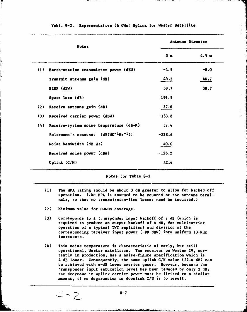
l
Tabl~ ~-2. aepre •• ntativa (6 GHz; Uplink for w.lt,r Satellite
Note.
-------(1) Barth-Itation trans.itter power (dBW)
Tran .. it antenna lain (dB)
EIllP (dBW)
Space lOll (dB)
(2) Receive antenna lain (dB)
(3) Received carrier power (dBW)
Receive-system noise temperature (dB-K)
Boltzmann's constant (dB(WK-IHz-1»
Noise bandwidth (dB-Hz)
Received noise power (dBW)
Uplink (C/N)
Notes for Table 8-2
Antenna Diameter
3 • 4.5 •
-4.5 -8.0
43.2 46.7
38.7 38.7
199.5
27.0 --133.8
-228.6
40.0 ---156.2
22.4
(1) The HPA rating should be about 3 dB greater to allow for backed-off operation. (~he HPA is ass~.ed to be mounted at the antenna terminals, so that no transmission-line losses need be incurred.)
(2) Minimum value for CONUS coverage.
(3) Corresponds to a tcln9ponder input backoff of 7 dB (which is required to produce an output backoff of 4 dB, for multicarrier operation of a typical TWT amplifier) and division of the corresponding receiver input power (-99 dBW) into uniform 10-kHz increments.
(4) This noise temperature is c!~.uacteristic of early, but still operational, Westsr satellites. The receiver on Westar IV, currently in production, has a noise-figure specification which is 4 dB lower. Consequently, the same uplink CIN value (22.4 dB) can be achieved with 4-dB lower csrrier power. However, because the ~ransponder input saturation level has been reduced by only 2 dB, the decrease in uplir.k carrier power IllUst be limited to a similar amount, if no degrejation in downlink CIN is to result.
8-7 ~ ~ I
$'*1!tsxnmsftr·g ,.. ... e;..";'''''''''::h'd~~.'.C __ ~~~~_~~~_~,~,j

I,'
I :,
~
I
r
inclu.ion of a tera for additional propa.ation 10..... 'or PS' the W •• tar 1 valu. of -92 dBW ha. ~ •• n u •• d. Althoulh a COMUS-cov.ra,. b ... will alway. have a aini.ua .ain of about 27 dB, inclu.ion of the OR t.ra allow. for hi.h.r lain. achiev.d throu.h the u •• of .pot b..... 'or Equation (2) t· be valid at any frequency, the .. arth-.tution 4nt.enna ., .• t b. repr ••• nted bl • te~ proportional to it. ar.~, ,ath.r than by it. goin.
Curr.nt .atellite. u •• travelin,-wave-tube (TWT) final .. plifi.r., all of which have .iailar tran.fer charact.ri.tic. (i ••• , output v.r.u. input backoff), r •• ardle,. of the .aturation output power l.v.l. Th.r.for., Equation. (1) and (2), which are ba.ed on corre.pondinl value. of input and output backoff (7 dB and 4 dB, re.pective1y) for multicarri~r operation, con.titute a con.i.tent rair of condition. for any TWT final ftmplifier. The num.rical value. in the.e .quation. will vary aomewhat if .y.tem con.ideration. dictate a diff.rent operatin, point. In addition, the trander chllracteri~tic. of the tran.ponder will be .rADewh~t different, .hould .olid-.tate mpllfiere replace the TWT .. plifier~ pre.ently in u.e. De.pit. the.e qualification., Equation. (1) and (~) provide a reliable rough auide to the .atellite and .~rth-.tation par .. eter value. required to e.tabli.h communicationa of .ati.factory quality.
C. CHANNEL DATA RATE
It il appropriate at thi. point to conaider the queltion of al.igning each carrier I dilproportionate ahare of transponder EIRP relative to the fractional bandwidth it occupiel. With the satellite pAr .. etleri previously a .. umed, this a .. ig1UDent is the only meana of overcoming the (C/~)theraa1 deficit exhibited in Table 8-1 for a 3-m earth Itation. Although the choice of a 10-kHz carrier noise bandwidth wa. arbitrary, the (C/N)theraal deficit would be the aame for any other bandwidth.
The required uplink tran.mitter power, on the other hand, i8 directly proportional to the carrier noiae bandwidth, al well aa to the downlink BIRP per unit bandwidth. There will generally be an upper limit placed on the transmitter power by either technology or COlt conliderationl. It may be necealary, therefore, to reduce the carrier noise bandwidth, through 8 reduction in data rate, aa thG downlink EIRP per unit bandwidth is increaeed.
The power rating of an BPA juat capable of making up the (C/N)thel,al deficit of 3.7 dB is shown in Figure 8-1 al a functio~ of the channel data rate. For thil purpole, the dete rate haa been taken al 0.4 time~ the carrier noise bandwidth (lee Note 6 to Table 8-1). In addition to the nominal tranlponder input laturation power of -92 dBW used in Table 8-2, two lower valuea are considered in Figure 8-1. Because uf recently improved satellite receiv!r noiae figures, the input saturr~:on lev~l on soon-to-be-launched satellitea can be reduced without sacrifi~.ng uplink signal qUdAity (see Note 4 to Table 8-2). It should alao be recognized that the aatellite re~eive antenna gsin liated in Table 8-2 is a minimum value over CONUS. Where the gain is actually higher, a corresponding reduction in tranamitter p~wer ia ~oasible.
8-8 ~ -It ~ J
1J
----~ ... -.~ ---'0/-",= .W' ___ ... ~~ •• , .• -~ ••. ~-.... - •••••• J

~ I
8r-------~--------,~--------~-------,~----~-r------~
7
6
,I
S -
3
2
UPPER LIMIT WITH -25 d8 SIDEL08ES -------- -------
8 12 16 20
CHANNEL DATA RATE, kb/.
Figure 8-1. garth-Station Tranlmitter R.equirementl with 3-m Antenr.a
8-9
2 ..
~ ~ ,i 1
~ "1 '.~
f, j
:~ ;i
~
. _____ • __________ ""'"·""~':Zc;;u~~"'" .... ~ .. "~·'m!" , .. " ... "., •• Q-......."""~"""'''''.~~.J

I
~
~iF ",' - . Ii ., "a'ol,,-'-M
In coaputina the pover r.quir •• ent. il1u.tr.t.d in 'ilure 8-1, no i.prov •• llt in the C/IM r.tio w ••••••• d ••• r •• u1t of t". incr •••• d pow.r p.r c.rri.r. B.c.u •• the pover in •• ch c.rri.r .u.t be incr •••• d by 3.7 dB to uk. up the (C/N)th.rul, d.ficit of Uk ••• ount, th.re ta only .noush power per tr.n.ponder to .upport 431 of the nuab.r ~f c~rri.r. p.r.itted by the tr.n.pond.r bandwidth. If th ••• c.rri.r •• re unifor.ly .p.ced in frequ.ncy, the C/IM r.tio will in f.ct be unch.na.d. On the oth.r h.nd, if the fr.quencie. to be occupied .re •• l.ct.d in • r.~doa unn.r, the C/IM r.tio. for the occupi.d fr.qu.ncy .lot. will typic.1ly be r.duc.d by 3.7 dB. Thi. C/IM reduction IIII:lo,. be tr •• t.d ••• n .dditional urlin to lu.rd .I.inu •• itu.tion in which di •• i.il.r c.rri.r., oceupyfna the •••• tr.n.ponder .nd r.pre.enttna other .ervic •• , s.ner.te 1.rler-th.n-.nticip.t.d inter.odul.tton product ••
Pre.ently, •• nuf.ctur.r. of .olid-.t.te •• p1ifier. Mt 6 GRz .re producfnl unit. r.ted from. coup 1. ~f w.tt. up to (in one or two c •••• ) 10 W. A 5-W r.tina will be t.ken .a r~pr •• ent.tive of •• p1ifiera th.t will be re.dily av.il.ble in the next few ye.r., at pric.a th.t will not aignific.ntly imp.ct the coat of • 3-. e.rth atation. From ptsure 8-1 it ia aeen that, with current operational .atellitea CPS • -92 dBW), • 5-W amplifier ia conatatent with a channel data r.te of 12 kb/a. With We.tar IV, on the other h.nd, which w11l have .n input saturation le,'el of -94 dBW, • data rate of 19 kb/a could be aupported. The l.tter fiaure ta essentf.lly equal to the 20-kb/a co.posite DSG polling rate projected for a large utility in the year 2000.
D. INTERFERENCE WITH OTHER SATELLITE SYSTEMS
Interference may be injected into other satellite systems on either the uplink or the downlink. There ia the potential for excessive uplink interference because of the small (3-m) antenn •• suggested for distribution-system use. Antenna sidelobe ~ain tend6 to be invariant to the antenna diameter. For example, the CCIR recommended sidelobe pattern, 32 - 25 log 8, ts independent of antenna size for .ntenna d:~meters gr~ater than D/~ • 100. To sstisfy a fixed on-axis EIRP requirement, the t~an8mitt~r power must be increased as the diameter, and heri:.e the on-~::!'" gain, is decreased. The EIRP in a particular off-axis direction, therefore, mUb~ increase as the antenna size is reduced.
Use of a 3-m antenna with a Westar satellite would require that 8
coordination procedure be initiated with the operators of satellite systeus that could be adversely affected. This procedure is necessary because the original Western Union filing with the FCC did not provide for transmission with antennas of this size. Failure to reach agreement on a set of opp.rating conditions satisfactory to all parties would, in all likelihood, preclude FCC approval for the proposed satellite links.7
In evaluating a new application, the FCC is Ukely to consider a proposed ceIR Recommendation setting limits on the permissible values of uplink EIRP (Reference 22). According to the proposed Recommendation, earth stations transmitting at 6 GRz shall be limited in their emisstons as follows:
7Private communicat1~n with R.G. Gould, Telecommunications Systems, Inc.
8-10
I ~~
;
l ~~

~
I
Anale Off-Axh Maxi ... BlIP
, • 5 d.. ~ 8 48 de.
48 de. ~ 8 180 de.
(35 - 25 1018) dBW/4 kHz
-7 dBV/4 kHz
Attention will be focu.ed on the cio.e.t pair of .ateillte •• for a alniaua eatellite .pacina of 3 de. alona the .eo.tationary arc. The .. xi.u. peral..ible BIRP in any 4-kHz bend. in the direction of .uch an adjacent •• ,telUte. 1a 23 dB~.
The on-axil 8ain of a 3-. antenna at 6 GHz t. 43 dB. the antenna ,ain in dB. relative to the on-axil .ain. in a off-axi~. In addition. let PT be the tran.aitter power in condition to be .atisfied Is then
Let Gr (<<) represent direction « de8 dBV. The
(3)
Note that PT is the total tran.mitter power. rather than the power per 4 kHz. The re •• on il that. reaardle~. of the data rate. and thus the occupied bandwidth. the carrier-acquisition portion of the preamble i. a~sumed to be transmitted as an unmodulated carrier. During thl. interval. therefore, the full tranlmitter power is concentrated in an extremely narrow band.
In Figure 8-1, the HPA ratina corresponding to the maximum permi.aible transmi tter power is lnd f,cated for relative aidelobe aains of -23 dB and -25 dB. The latter value ~ermitl u.e of an HPA rated at 6.3 W, correlponding to a data rate of 15.2 kb/., with Ps • -92 dOW. In a study of a lafae number of exi8tl~~ amall antennal (Reference 23), Janky et al., found that the olf-axi. 8ain was upper-bounded In nearly all ca.el by the expression, 6 + 30 108(8/80) dB, where is the off-axis anale and 80 is the half-power beamwidth. The half-power beamwidth of a 3-m antenna at 6 GH. il 1.2 dea. At an anale of 3 de8 off-axis, therefore, virtually any commercially available 3-m antenna will have a 8ain of at most 18 dB. This gain is equivalent to a relative 8aln of -25 dB, because the on-axis gain at 6 GRz is 43 dB.
On the other hand, some of the antennas exaained had sidelobe gains a8 much a8 10 dB below that 8iven by the upper-bound expression. It is not pCdstble, from th~ data presented, to a880ciate specific a&itennas with quoted performance levels. However, "no correlation was found between sidelobe performance and antenna cost on the one hand or between sidelobe performance and ar.tenna size (in wavelengths) on the other" (see Reference 23).
In 8eneral, no attempt was made at sidelobe suppression in the deaign of the antennas examin~d. A reduction in aidelobe level can be achieved by increasing the taper of the feed pattern across the aperture of the r~flector. Specific aidelobe-reduction resulta u8ing the tapered-illumination technique are cited by Yokoi, et al (Reference 24). The measured radiation pattern of an offset-Gregorian antenna wa~ found to have a sidelobe envelope bounde1 by the expression, 32 - 40 log 8 dB. In particular, the peak of the secont side-
1.
I'
"
i
I , .

P t
lobe, which corre.pond. to • direc tion 3 de. off-.xi. for • 3-. .ntenn •• t 6 GRI, W •• J4 dB below the on-.xi ••• in. Siai1.r p.rfora.nc. i~ reported for an off •• t-C ••••• r.in .ntenn ••
It i •• vid.nt froa the precedin. di.cu •• ion th.t -25 dB, .nd perhapi leveral dB lower, .ide10be performance (for the .econd .idelobe) il routinely attainable. Re1ativ. galn. b.10w -30 dB, a1thou.h attainable, .en.ral1y r.quire .o.e fora of .ide1ob. lupprel.ion. Th ••• lower lainl .hou1d not b. nece •• ary for the prel.nt application, b~caul. a r.1.tive .ain Gf -25 dB permitl the u.e of an HPA rated at 6.3 W, •. .;cordinl to the propoted CCIR Rec ollDend a t ion.
The adequacy of the int~rf.rence criterion let forth by thi. propoled RecolIDendation can be alle.led al follow.. The earth-Itation BIRP needed to saturate a current C-band tranlponder it at'out 84 dBW. If the maximum level of interference, stated for a 4-kRI band, were maintained aeroll the full tranlponder bandwidth of 30 MHI, t~e carrier-to-interference ratio (C/I) at laturation would be 84 - 23 - 10 101 (30 x 106 /4 x 103) • 22.2 dB. (Identical latellite antenna gain in the d~rectionl of delired and interfering earth Itationl ha. been .. lUlled.) An equal ."lOunt of interference could, in principle, be received from the other a~jacent late11ite, thereby reducing CII to 19.2 dB. If, in addition, the interfered-with tranlponder il operated in a v,'Jlticarrier, backed-off falhion, C/I would be lower by an amount cornuponding to the input backoff. Clearly, the proposed RecolIDendat ion does not prl,vide adequate protection from adjacent-latellite-IYltem interf~cence under an arbitral' .ly chosen let ~f op~ratina conditionl.
The permissible level of i"terference (per 4 kHz) in a specific situation depends on the total power and Ipectral characteristics of the signals involved. Certainly, one or leveral narrowband cstriera wi 11 not interfere si6 ni ficant ly with a wideband TV or FOM/PM telephony carrier, provided the re~aining carriers in the interfering transponder present 8 conliderably lower interferencE profile. On the ocher hand, single-channel-per-carrier (SCPC) tranlmissions in an adjacent satellite would be especially vulnerable to interference of the type described, because of their narrow bandwidth.
The variable effect of interference from a set of narrow~and utility carriers demonltrates the need for coordination with the administration of adjacent satellite systeml. Although the proposed CCIR Recoaaendation has been used as a guide in d~termining permissible levels of interference, as much margin as possible should be built into this aspect of the system design.
As an illustration of the ~ignificance of carrier bandwidth on potential interference into an adjacent satellite Iystem, American Satellite Corpclration (ASC) is planning to petition the FCC in early 1981 to permit duplex transmission with Westar satellites using 3 .... earth-station antennas. Wit.h the present 4 deg-spac.'.ng of C-band satellites, ASC will requelt permission to transmit at data cates up to 56 kb/s. If the minimum satellite spacing is reduced (by the FCC) to 3 deg, a lower max,mum data rate will be requested.8 The plans of ASC reinforce the idea tht~ 3 .... earth stations can be combined
8pr ivate communication with ABC.
8-12
l ,1 ,~
1 l l ;!
.1 l ~ " "
,~
~ '" " ....... _~~." __ ._;;",,.~.:. .. , .. .<!i , .. ,.: ........ ,~,~..........& .... *" eir 'h~~ ~1 ... lIiilllliirif_m'1l1i1iW_' 1IIII .. liIlIilrllllll'tlllt_ .... t~ •. -..... t_·""'· .... ,,, .. t ... t_.~ ___ .,~~-'~ ..... ~~,~'t_.~_., .~_. ____ .... _".~j

with curr.nt C-band .at.llit •• for di.tributioa-.y.t .. c~nication., .'pecially if the chann.l data rat. i. r •• trict.d to 20 kb/ ••
Bulk-pow.r-.y.t .. c~nication. with 4.5-. ant.nna. pr ••• nt. a t •••• r int.rf.r.nc. probl .. , b.eau •• the additional 3.5 dB of on-axil ,ain r.duc •• by a Ii.Uar aaount the tran •• itt.r power n •• d.d to produc. a .pecifi.d od-axl. IIIP. The reduc.d tran •• itt.r pow.r r •• ult. in a ... ller off-axil IIIP.
I. IARTH-rCATION PIICIS
Two dUfereni; earth-.tatior, anr·dnna .iz •• have b.en .ull.st.d for 0P81··.tion wit\' C-band .. t.nit •• 1 4.5" f'or bulk-power-1l.taa operation. and 3 • for dbtribution-.y.t .. application. C.ncluClinl nsc.). Becau .. of the extre .. reliability required in the bulk-pOW.I' .y.t .. , coapl.u redundancy (with the exception of the antenna) i. a •• uaad for the 4.~ ... t.r .tation.. The 3-. atation~, on the other hand, can be .. d. nonredundant.
Component pricea for an operational .tation of each type are liven in T,lble 8-3. The.e .hould be ~·ellarded aa ele.entl ot the price that would be paid to an earth··atation integrator, rather than price. of cOtlponent aanu-
Table 8-3.
Component
Antenna subsystem
Low-noise receiver
HPA and power supply
Up/down converter
Baaeband equipment
Automatic redundancy
Teet and integration
Total
larth-Station Price lati.atea ($K)
Single Unit
7.0
1.5
3.5
9.0
12.0
8-13
Antenna Diameter
4.5 •
Per Station
7.0
3.0
7.0
18.0
24.0
10.0
5.0
74.0
3 •
3.0
1.5
9.0
12.0
3.0
32.0
~
i .,
-.- •• _ •••• u •• "~."= .• ,,~~%,,""-•• _.~~~"' .•• 2'3.'S' rap··_-InsCd.r+ bton' ',"",,-'~~..i~~, •. -.~=.~_-.>..u,"-,="~_..w_.~_~ .. u .•• ~~, __ .... u_.c..,J

I
~.
factur.r.. Th. '9,000 up/down coov.rt.r i~ • rec.nt .icro.trip d •• ian that i. r.pr ••• otativ. of d.vic •• pr ••• ntly u •• d io C-b.od co..uoication.. Stability of olcillator. incorporat.d in th ••• uoit. r •• ult. in fr.qu.nci •• at th. output. of the up/down coov.rt.r that ar. typically within 1 kBa of oGainal value.. (rr.qu.ocy .hift. due to io.tability of the .at.llit. fr.qu.ncytrao.latioo o.cillator ar •• li.ioat.d throulh u •• of a pilot tona tran •• itt.d by the .. ~t.r .tation.>
Th. up/down coov.rt.r h of the double-coov.rlion typ., .0 that operation throuah an alt.rnat. tran.pond.r r.quir •• ooly a chan •• of cry.tal. Thi. op.rational flexibility i ••••• nti.l in a bulk-pow.r-,yet ... arth atation, where the duration of any outaa • .uet b. minimi •• d. It ie aleo hiahly deeirabl. for the DSG population. Subetitution of a einale-coov.reion up/down conv.rt.r would reduce the unit price fro. '9,000 to p.rhepe '5,000, h,Mever, the r.quir.d r.tunina proc.ee for traoe.ieeion throulh a e.cond tranepond.r .. k.e thie an und.eirable alternative.
Tho coet of bae.band equipment for a TDNA earth etation of the type under coneideretion ie difficult to e.tablieh wi~h any pr.ci.ion. Moet TDNA darth .udone ar. ded,n.d for cetabin.d voic(l! {lnd data traffic, at hlah data ratee, and conl.quently are quit. co.tly. In Rafer.nce 21, Hu.t.d lnd Dinwiddy de.cribe a TDNA earth-etation deeian, for data only, that ha. an eeti.sted recurrina COlt of $10,100 for the baeeband equipae~t. The TDNA buret rate is 4 Mb/e, while the data rate of an individual channal ie 128 kb/l. The e.timated nonrecurring COlt to develop an engineering model and production prototype i. $260,000.
Baleband equipment developed for the preaei1t applicat.ol. would differ in leveral relpecte from that deecribed in Reference 23. The TDNA burlt rate and the data channel (RTU data) rate in the preeent ca.e would be limited to perhape 100 kb/l and 5 kb/l, relpectively, for a bulk-power-Iyatem network. On the other hand, the frame period of 2 I i. 10 times larg~r than the value assumed in the paper. In addition, a coding/modul~tion combination best luited to the prelent application would have to be lelected. Despite thele differences, both the recurring and nonrecurring COstl Ihould be limilar to thOle of the baseband equipaent delcribed in the paper. However, to acco~nt for the effectl of inflation, the recurring baaeband-equipaent cost will be t"ken aa $12,000.
The $10,000 allocated to equipment that automatically Iwitchea over to a redundant unit in the event of a component failure il little more than an educated aueu at thia point. A form of "chain" redundancy il allumed whereby no attempt il made to identify the failed component b~ electronic meana; inatead, a redundant chain of componentl, from baaeband to RF, is lubstituted for the chain originally in ule whenever a failure is detect.ed.
The need for automatic-Iwitchover capability is a subjective matter. At a manned generatiof. plant, with the ea!'th atation auumed to be! cloae by, a failure can be rectified in minutes by manually .witching to the redundant component. During thi. brief period, the alteenate communication mode would be employed. In the Collie of an unmanned BPS or Iwitching atation, reliance on the alternate communication mode would be required for a longer period of time.
I j
j ci
i I ,

Th. pric. of • fully r.dund.nt 4.5~ •• rth .t.tion with .utoaatic.witchov.r c.p.bility i ••• t~t.d .t '74,000, th.t of • nonr.dund.nt 3.5~ .t.tion, .t '32,000. Tha •• pric ••• r. ba.ad on r.currina co.t. only. Hovav.r, if •• t.llit. tr.n .. i •• iQn .hould b. widaly .dopt.d for bulk-power-.y.t ... nd DBG control, •• uffici.nt nuaber of .arth .tation. would be order.d .0 th.t nonr.currinl ~o.t. would not .ilnific.ntly i.p.ct th ••• rth-.t~tion pric ••
If it ver. d •• ir.d to d-.on.tr.t. the u •• of •• t.llit. tr.n •• i •• ion for control-.y.t .. c~nic.tion., it would b. n.c •••• ry to u •• b ••• b.nd .qui,..nt th.t i • .or ... nar.l-purpo •• in nature th.n would be the ca •• for .qui,..nt d.v.loped •• p.ci.lly for the utility .pplic.tion. ror .x .. pl., Dilit.l C~nic.tion. Co~por.tion .. rk.U • 4. 5~ •• rth .t.tion c.ll.d • DYNAC t.rain.l with d ... nd-••• ilned TDKl c.p.bility. Th. t.rain.l h •• 42 port. H ••• , it c.n .c,co.aod.t. 42 d.t. chann.h) Gnd h •• conaidar.bly .ora dialno.tic c.p.bility th~n would be r.quir.d for tha utility .pplic.tion. In ••• 11 qu.ntitie •• nd without r.dund.ncy, tb ••••• rtb .t.tion •• all for .bout $50,000.
8-15
I
I 1 !
1 I
r ;
i~ t"
il ') " i
~ .1
_ .. _, .. _,,,"_~._'~ __ ,,O_I.'ll,'~,~",,,,,-,~~' '1''8';;5;.?!I'''''-::-.':';· :Zrtd __ . 1 ,~_., .!.,,",u." '_,~~~_~_,~"-~_,="c~, ~11~",-""j

9 l _.
SECTIOR IX
COIICLU8I0I8 AltD UCOMMINDATION8
It ha~ been d .. on.trated that bulk-power-.y.t .. c~nication. can be provided via .atell{te, at rea.onable coat, u.ioa pre.ent technololY. Whether u.ed in a pri .. ry or backup capftcity, .atellite tran •• i •• ion can .ianificently i.prove the overall ca.aunication-.y.t .. reliability. It i. anticipated that the attractivene •• of .atellite link. for a particular utility will depend in part on the extent t,o '~ich the cCUlUnications capability need. to be uPlraded aa the reault. of control-.yat .. .odernication.
Becaule bulk-power-ay.t ... atellite link. would pre.uaably provide one of two alternate c~nication .ode. betwean e~ch pair of in.tallation., the lwo modea would have to be .ade .utually ca.patible. Por ex .. ple, if the other (terre.trial) mode i. already eatabliahed and operatea with half-duplex tr~n .. iaaion, two pOlaibilitt~a exiat. lither the aatellite linka would have I, operate in the a.e .. "ner, with an attendant increaae in operational L~plexity, or a separate aet of protocol a would have to be eatabliahed for .atellite tranamisaion. The latter ~hoice impliea a replication of certain functiona and equipment that would not be necessary if a common aet of protocola could be adopted.
DSG ~ommunicationa via .atellite ia alao feaaib1e uaing preaent C-band latellitea, for thOle unita large enough to warrant the eatimatad $32,000 expenditure for a 3-m earth atation. Pending FCC approval of C-band tranami.aion by 3-m atation" a 4.5-m antenna could be employed, at an additional coat of about $5,000, at aitea where phyaical lize ia not a problem.
C-band communications would aeem to provide an ideal meana of control for remotely located DSGI, wher~ the terrain rendera the terreatrial alternatives infeasible, or at least unattractive. In more populous areaa, the number of sitea that can be coordinated with terreatrial aarviee. for C-band operation .. y be limited. Although Ku-band transmiasion would largely avoid thil problem, operation in this band depftnds on the deployment of a aate11ite intended to accommodate narrowband tranamission. On the other hand, the advent of a latellite payload ieaigned for general distribution-aY3tem uae could aerve DSG needl as well.
The feasibil ity of eoaaunicat ing via IateH ite to distributio.,-a.ystem sites for operationa1- and 10ad-management purposes hinges on two factorsl the need for a new frequency allocation and the cost of earth-terminal equipment. These two factors are interrelated, as equipment prices generally increa8e with frequency. Because of these potential hurdlel, the feaaibility of using S-band frequencies deserves further examin&tion. Specifically, the compatibilicy of satp.llite transmission with terreatrial servi~ea at S-band should be investigated.
Regardless of the frequency selected, a high-gain satellite antenna would be required to permit the use of low-cost gr~und equipm~t. There are plans to demonstrate low interferenc.e, mUltiple spot-beam, h4.gh-gain antenna
9-1 1 ~1 j
_~ •• __ b. tt~· ........... >U..~,_~_-_·:...",c: ..... _~J)C...J. ""~ ........ ",,,' "'t"7 ... itil!il?3'iiOlI"'iioOI=",, __ !, ... ~_=tr""'iIII •• fillo.IiOI(""_"_,;it·n"""'''''~~"..L·.~,,~"_"_.·~t. ri''" @' .wn_ .. "a~m'~'~"'hl~L~~j

t.chnolOIY for the Land Mobil. Sat.llit. Servic •• but the fr.qu.ncy band allocat.d to thia •• rvic. i. not availabl. to the utility application. Non.thel •••• there ar ... ny attr.ctiv. f •• tur •• of thi. t.chnololY which •••• • ppropri.t •• nd .ttr.ctiv. to the proj.ct.d futYr~ ne.d. of tba &l.ctricutUity indu.tr~. Th ••• includ ••••• of wid. aua cov"uC •• pot.nti.1ly lowco.t Iround te~inal •• n.twork fl.xibility. rel~t{v. tnd8pand.nc. froa the power .y.t .. , .nd hilh lnfor.ation tr.n.f.r r.t. c.p.billty. Th ••• ch.r.ct.ri.tic •• rlue for further lnv •• tll.tion of utili".tion of •• t.llit •• with l.rl • • nt.nna •••• n option for .. ny .l.ctric-utility functi~~.. If n.c •••• ry. the curr.ntly .v.il.bl. fr.quency .lloc.tion ahould be r.exaatn.d.
Th. co.t eff.ctiv.n ••• of ••• t.llit~ n.twork wh.n .ppli.d to. or .bar.d by. the electric utility indu.try r ... in. to be •• t_bli.h.d. but .h.r.d u •• ••• aa .o.t proalaina. a..id •• the L.nd Mobil. S.t.llit. S.rvic •• oth.r potenHal u •• ra h.vina at.U.r r.qulr .. nt •• ilh, includ. oU .nd I •• dfatributto'., production. and explor.tion coap.ni ..... dic.l d.t •• xch.nae n.twork •• em.ra.ncy w.rnina network., .tc.
In liaht of the .bov., the followina ne.r-t.ra .ctlona .r. r.co.a.nd.d:
(1) Conduct. follow-on tr.fflc .tudy to include mobile co.aunic.tion. r.qulr ... nt8 af el.ctrlc utiliti ••• nd the .pecl.l requirement. of major tran.mi •• ion utilitle •• uch •• TVA, Bonneville, or the Weatern Are~ Power A~~fni.tration.
(2) Conduct a follow-on fr.qu~ncy manaament .tudy to inve.tiaate interference, coordination, and a •• ignm.nt t •• ue. tn greater depth, p.rticularly at S-band and lower.
(3) Vorumulate a program of experimentally exploring, in partnership with. utility, the feaaibUlty of key concepta developed in this and the follow-on studiea, but u.ing exi.tinS C-band .ateillte •• Such a prog'cam might includo, for example, the e.tabH.hment of all experimental link for monitor .~d control of v.rious bulk-power.yatem unit ••
(4) Identify and survey other potential u.ers of a "nMrrow band," fixed-.ate1lite 6ervice .Vltem. Identify user requirement. and develop e.timates of potential communications traffic.
9-2 "~
l :1 \j
~
""'"h •. m_~.""·~; ~, ....... _w~ •• ~" .. ,a, YI""!t',W'""",,·, __ 'arftttt: 0:5 "h' "~"""',lt,"'""~' • "u'"~~_"_~"_~~'~5,'''3~,.,,.' ... _VU''h'_ ~,j

I I
I I
1.
2.
3.
4.
5.
6.
7.
8.
9.
10.
11.
12.
SICTION X
IIPlUIClS
aarnett, I. M., A Pre1i.inary I.ti.at. of 'ut~ra Co.aunlcationa Traffic for the 11ectric Power II.t .. , Jpt Publication 81-41, Jet Propul.lon tabOratory, 'a.~d.na, Ca I'ornia, April 1981.
IIIE laco..ended Practice for Maater/a .. ote Co.aunicationa, WorkSn, laper UG 77.l, lan. 15, 1980.
natttute
, California,
Lewla, s. H., "T & 0 Rea.arch Showa R.aulte," Tranamhalon and Diatribution, Vol. 32, No. 12, pp. 24-25, December 1980.
and
Weber, W. J., III, Hulti-Servic. Narrowband Prolram Plan - Initial Studies, Internal Hemo, Jet Propuldon Labor ... tory, Pa .. dena, Caitfornia, Har. j, 1980.
WEiber, W. J., IE, Nadert, F., and Goldman, A. H., Jr. TechnololY Considerationa for a 1990'a Operational Land Hobile Satelilts Servic., Sixth Internutional Telecommunication and Computer Expoaition (INTELCOH), Los ~ngeles, Californil" Nov. 10-13, 1980.
Kirkham, H., Nightingale, D., and Sha1lllD't., S., Energy Managellent System Deaign with Dispersed Storage and Gener.tion, 1981 Winter Meeting of IEEE Power Engineering SocIety, Atlanta, Ceorgia, Feb. 1-6, 1981.
Definition, Specification, and Analysia of Manual, Automatic and Su~ervisori Station Co~trol and Data Acquisition, ANSI/I!!E itandard C3 .1, 197 .
"Southern California Edison Ra18ea Commitment to Alternative Energy in Hajor Change," The Wall Street Journal, p. 5, Oct. 20, 1980.
10-1
l
1.
a 11 ;~
1
. __ . ".," __ ."'_'.'_"~"".' .=.,_.",~'''k.''-''"' __ ... "," __ Slrr_'_rZ ri'W' ft" -'" .... ".;-..:, •. ,· .. k. ,_ . _ .. ~ .. ~_ •. ,,~~~ .v~,_~,~·.~,,~ .. , .. · .. ,,· .",-, ".-- ....... ' "s,j

-----
.nallCl' (Cont'd)
13. ' .. dieon to Work on lenewabla Inar" '1'0,1' •• " Lo. An.ala. TiM'. p. 1. Oct. 18. 1980.
14. Dorian, C ••• ott •• J. I •• "inhart. I •• and Wei ••• R •• '~he 1979 World Adainietrative Radio Conference and latellite C~nieation •• " C .. at Technical Review. Vol. 10, 10. 1. pp. 1-26. Sprina 1980.
15 By Liacco. T. I •• ty.t .. Control Center. for Cen4ration-Tran .. i •• ion Sy.t ... , ha'!'~dout at Sixth aiennlal Work.hop on leai Ti. Monitorm, and Control of Power Sy.t ... , Univer.ity of Wi.con.in, Madi.on, Wi.con.in AUlult 1980.
16. Satellite Ca..unication. U..on.tr~tion for lia.ara Mohavk Power Corporation - ,inal leport. Iy.t ... Control. Inc., leport MPL '81-85111, Palo Alto, California, Dec .. ber 1980.
17. A Stud! of t.he CO.lI 0' Alternative C~nication Sy.t ... for Utility Di.tribution Autaaat{on, Sy.t ... Control, Inc., Palo Alto. California, 'ebruary 1979.
18. "Ca..unication Alternative. for Di.tribution Meterinl and Load Manaa.ent," aecord of Panel Pu .. nution., ),979 Sua.er Power Meetinl, edited vel"ion printed in IEEE Tren.action. on Power Apparatu. and Sy.t .... Vol. PAS-99, No.4, pp. 1048-1055, July/AuIU.t 1980.
19.
20.
21.
22.
23.
24.
Sardella, V., "Interactive Cables 'ederal Policy and Prolr •• ," IEEE Tran.action. on Com.unication., Vol. 23, No.1, pp. 171-178, January-19'15.
C.paneUa, B. J., and Ho~~on, K., "Open-Loop TDMA Frame Acquilition and Bynchrnnization, II COII.at Tec~\nical Review, Vol. 9, No. 2A, pp. 341-~85, 'all 1919.
Hu.ted, J., and Dinwiddy, B., Low Co.t Satellite Data Tran.mi •• ion Network. U8i~a Demand A •• ianed TDNA, Fourth International Conference on Ui.ital Satellite Ca.aunicationl, Montteal, Canada, October 1978.
Gould, R. G., International and Dome.tic Refulation. Affectin, the Efficiency of orbit and Spectrum Utilitizat on, IEEE International Conference on r.ommunication~, Toronto, Canada. 1978.
Janky, J. ~;., CIt al., "New Bide1abe Rnv'llope. for Bmall Aperture Earth Station.," IEEE Tran.action. On Broadca.ting, Vol. 22, No.2, pp. 39-44, June 1976.
Yokoi, H., Kurihara, H., and Akjl.awa, M •• Improving the Radiation Characteri.tic. of Aperture~~~ l.EEE International Conference on Communication., Toronto, Canada, 1~78.
10-2

I ~
APPIImIX A
DI8PIUID 8TOIACI AID ClIlIATIOli DErINITIOItSl
Hydroelactric Puaped Storaae
Solar Thermal Ilectric
Photovoltaice
A bidirectio"al hydro p~ant pu.p. water fro. a lower re.ervoir to a hiah.r one durina period. when the utility i. under liaht load. Durina heavier load period. the hydro plant aenerate. power from the flow of wa~er down to the lower re.ervoir. The.e flow. may be combined with a net averaae flow for irriaation or municipcl water .uppiy. Iconomie. of .cale have favored larae in.tallation., but .. aller one. (of only a few aegawatte) are under active conlideration, elpecially on the Welt Coaet.
Thele .yneal collect lolar radiation to heat a working fluid to high t~mperaturee to operate a mechanical-electrical aeneratina lye tea. Thermal energy storage may be included in the approach, and excess heat from the sy.tea can be uled for other purpoeel, such ae spAce heating. A wide range of power levele and equipment types can uee this approach, however, the aethod ie not preeently full, commercialized.
Photovoltaic celle con',ert 1:..ght energy directly into electrical energy by the s~imulation of the junctions of dissimilar materials by solar photons. Low solar inteneity at the earth's surface (about I kW/m2) and relatively low cell efficiency (S to 20%) combine to require extensive land areas to produce significant amounts of power. Insolation cycles and variable weather conditions further limit the amount and availability of photovoltaic power; convereion equipment is required to couple the dc output of the solar array to an ac power system. Coneequently, a significant problem faced by users of photovoltaic systems is the high initial capital cost. Because considerable resources are present ly being devote,:! to the reduction of these costs, competitive photovoltaic equipment should become available by the mid 1980s.
l.r:J;~en from a preliminary version of Referenee 10.
A-I

Wind
I
~
Storase Battery
Hydroelectric
Wind .eneratlon syst •• s e.ploy a propeller or a wind turbine to drive an alternator either directly or throuah a aearbox. For utilitle., the.e syste ••• ay con.lst of one or more .oderate-.lzed unit. (200 kW to 3 MW). Control s~·Jte.s for wind aenerators mu.t decouple the senerator In very llaht wind. to avoid havina the propeller driven by motor action. In very heavy wind. the system must again be shut down to avoid damage. Because of this, and beccuse wind is not generally a steady resource, wind systems presently are uneconomical. However, like photovoltaics, this i. a dynamic situation.
Stor~ge batteries are not truly sources of electrical power. In fact, their normal inefficiency involves a net power loss. However, the availability of power that can be rapidly controlled in combine- tion with a non-controllable power source (such as wind or Bolar) can provide a stead~er output to the power system. Batteri~
employ electrn-chemically dissimilar electrodes ~~ conjunction with an electrolyte to provide a means of convertina electrical energy to chemical form. This stored chemical energy may be subsequently released as electrical energy through a Buitable external circuit. For utility systems, an inverter iPo required to change the stored de energy into ac power although transformation and rectification are required to charge the battery from ac lines.
Storage, in general, improves the utility load factor and thus reduces the r.~L C~9t of energy by improving the use of existir~ equipment.
Hydroelectric plants convert the energy of naturally flowing water to electrical energy by using water turbines t~ drive electrical generators. Small ~nlts located on minor rivers or streams may usp this source of energy to supply local needs through connection to distribution feedera.
The economies of scale are such that rela~ively small hydro-generators are ecor'.Jmical. The technology is already developed.
A-2
~. i1
1

Co-•• n.ration i. the ooabined production of proo ••• h •• t and .l.otritlt,. lndu.tri •• aad utiliti •• ne.di., both of th ••• fo~ of .n.r., oan •• n.rall, achi.v. a net reward in co.t b.n.fit b, u.ina a facilit, that full, u ••• the h.at of coabu.tion. 'or .... pl ••• oa. •• au.t .t ... fro. a .t ... turbine .. , b. ..nt to nearb, c~rcial or indu.trial faciliti ••• Whil. the r .. ainina h.at and .t ... i. u •• d for local .pac. h.atina or .. nufacturina proc.,~.,. lacau ••• any co-•• n.ration faciliti •• u •• oil-fir.d .a. turbin ••• th., do not oontribut. toward a natlonal .oal of r.duc.d oil ~rt.. Row.v.r. cO-I.n.ration do .... plo, a full, d.v.lop.d t~cbnolo., and i. of ~diat. .con~ic b.n.fit. Co-,.n.ration .u.t b. con.id.r.d in an, di.cu •• l0n of D80.
A-3
~
'_""'tt'ff-.•. '.''''''''''''''_''''c''_'~ ", •• i",,~':"-",""'!!''''''SriM .... ·t.2 t :1'_ ... !,~_," .. """,."._"~ __ ~t"""",""~""''''._~t""", __ ~ __ ~t="".,,j