three-dimensional digital image correlation of a … · hydrostatic pressure tests ... two...
TRANSCRIPT

Duane M. Revilock, Jr.
Glenn Research Center, Cleveland, Ohio
John C. Thesken
Ohio Aerospace Institute, Brook Park, Ohio
Timothy E. Schmidt
Trilion Quality Systems, West Conshohocken, Pennsylvania
Bradley S. Forsythe
Honeywell Technology, Las Cruces, New Mexico
Three-Dimensional Digital Image Correlation of aComposite Overwrapped Pressure Vessel DuringHydrostatic Pressure Tests
NASA/TM—2007-214938
August 2007
Paper number 169
https://ntrs.nasa.gov/search.jsp?R=20070031571 2018-07-18T23:51:31+00:00Z

NASA STI Program . . . in Profile
Since its founding, NASA has been dedicated to the
advancement of aeronautics and space science. The
NASA Scientific and Technical Information (STI)
program plays a key part in helping NASA maintain
this important role.
The NASA STI Program operates under the auspices
of the Agency Chief Information Officer. It collects,
organizes, provides for archiving, and disseminates
NASA’s STI. The NASA STI program provides access
to the NASA Aeronautics and Space Database and its
public interface, the NASA Technical Reports Server,
thus providing one of the largest collections of
aeronautical and space science STI in the world.
Results are published in both non-NASA channels and
by NASA in the NASA STI Report Series, which
includes the following report types:
• TECHNICAL PUBLICATION. Reports of
completed research or a major significant phase
of research that present the results of NASA
programs and include extensive data or theoretical
analysis. Includes compilations of significant
scientific and technical data and information
deemed to be of continuing reference value.
NASA counterpart of peer-reviewed formal
professional papers but has less stringent
limitations on manuscript length and extent of
graphic presentations.
• TECHNICAL MEMORANDUM. Scientific
and technical findings that are preliminary or
of specialized interest, e.g., quick release
reports, working papers, and bibliographies that
contain minimal annotation. Does not contain
extensive analysis.
• CONTRACTOR REPORT. Scientific and
technical findings by NASA-sponsored
contractors and grantees.
• CONFERENCE PUBLICATION. Collected
papers from scientific and technical
conferences, symposia, seminars, or other
meetings sponsored or cosponsored by NASA.
• SPECIAL PUBLICATION. Scientific,
technical, or historical information from
NASA programs, projects, and missions, often
concerned with subjects having substantial
public interest.
• TECHNICAL TRANSLATION. English-
language translations of foreign scientific and
technical material pertinent to NASA’s mission.
Specialized services also include creating custom
thesauri, building customized databases, organizing
and publishing research results.
For more information about the NASA STI
program, see the following:
• Access the NASA STI program home page at
http://www.sti.nasa.gov
• E-mail your question via the Internet to
• Fax your question to the NASA STI Help Desk
at 301–621–0134
• Telephone the NASA STI Help Desk at
301–621–0390
• Write to:
NASA Center for AeroSpace Information (CASI)
7115 Standard Drive
Hanover, MD 21076–1320

Duane M. Revilock, Jr.
Glenn Research Center, Cleveland, Ohio
John C. Thesken
Ohio Aerospace Institute, Brook Park, Ohio
Timothy E. Schmidt
Trilion Quality Systems, West Conshohocken, Pennsylvania
Bradley S. Forsythe
Honeywell Technology, Las Cruces, New Mexico
Three-Dimensional Digital Image Correlation of aComposite Overwrapped Pressure Vessel DuringHydrostatic Pressure Tests
NASA/TM—2007-214938
August 2007
National Aeronautics and
Space Administration
Glenn Research Center
Cleveland, Ohio 44135
Prepared for the
2007 Semi Annual Conference and Exposition
sponsored by the Society for Experimental Mechanics
Springfield, Massachusetts, June 3–6, 2007
Paper number 169

Available from
NASA Center for Aerospace Information
7115 Standard Drive
Hanover, MD 21076–1320
National Technical Information Service
5285 Port Royal Road
Springfield, VA 22161
Available electronically at http://gltrs.grc.nasa.gov
Trade names and trademarks are used in this report for identification
only. Their usage does not constitute an official endorsement,
either expressed or implied, by the National Aeronautics and
Space Administration.
Level of Review: This material has been technically reviewed by technical management.
This report contains preliminary findings,
subject to revision as analysis proceeds.

NASA/TM—2007-214938 1
Three-Dimensional Digital Image Correlation of a Composite Overwrapped Pressure Vessel During Hydrostatic Pressure Tests
Duane M. Revilock, Jr.
National Aeronautics and Space Administration Glenn Research Center Cleveland, Ohio 44135
John C. Thesken
Ohio Aerospace Institute Brook Park, Ohio 44142
Timothy E. Schmidt
Trilion Quality Systems West Conshohocken, Pennsylvania 19428
Bradley S. Forsythe
Honeywell Technology Las Cruces, New Mexico 88004
Abstract Ambient temperature hydrostatic pressurization tests were conducted on a composite overwrapped
pressure vessel (COPV) to understand the fiber stresses in COPV components. Two three-dimensional digital image correlation systems with high speed cameras were used in the evaluation to provide full field displacement and strain data for each pressurization test. A few of the key findings will be discussed including how the principal strains provided better insight into system behavior than traditional gauges, a high localized strain that was measured where gages were not present and the challenges of measuring curved surfaces with the use of a 1.25 in. thick layered polycarbonate panel that protected the cameras.
Introduction The advent of high performance aramid and carbon fiber has enabled the evolution of filament wound
pressure vessels capable of extreme energy storage capacity per unit mass. Starting in the 1960s and 70s, this potential was recognized by Johns and Kaufman (ref. 1), Lark (refs. 2 and 3) and Faddoul (ref. 4) at the NASA Lewis Research Center as a number of design and manufacturing studies began to investigate the technical feasibility of filament wound pressure vessels for space flight. Landes (ref. 5) and Ecord (ref. 6) published early work describing this technology with reported weight savings of 25 to 30 percent over comparable all metallic spherical vessels (ref. 7). Today (COPVs) are essential to numerous NASA power and environmental systems. The majority of older vessel overwraps are made of Kevlar (DuPont) 49/Epoxy Composites while the newer vessels have Carbon/Epoxy overwraps. The Kevlar 49 fiber overwrapped tanks are of particular concern due to their long usage and the poorly understood stress rupture process in Kevlar filaments. COPV’s store high pressure gases for four different subsystems on the Space Shuttle Orbiter. There are 24 COPV’s on each Orbiter ranging in diameters from 19 to 40 in. (fig. 1). These tanks were designed and developed in the late 1970s and most of them have been in service since delivery in the 1980s.

NASA/TM—2007-214938 2
Figure 1.—Locations of composite overwrapped pressure vessels on a Space Shuttle Orbiter.
The vessels have a thin titanium liner with a Kevlar 49 composite overwrap. The overwrap is multiple layers and is designed to carry most of the load. Because stress rupture in Kevlar 49 gives no forewarning, Schmidt and Ecord (ref. 8) at the NASA Johnson Space Center (JSC) initiated an accelerated stress rupture test program to lead service hardware in actual time at pressure. The occurrence of burst events in that test program motivated the NASA Engineering and Safety Center to establish an Independent Technical Assessment of the (COPVs) used in NASA applications. That assessment showed that the Kevlar COPVs used on the Space Shuttle Orbiters were beyond their original certification of ten years and that the risk of a stress rupture, a catastrophic burst before leak failure mode, was greater than previously believed (ref. 9).
While existing long term data show that the stress rupture process in Kevlar fiber is a function of fiber stress, temperature and time, it is questionable whether the standard stress—rupture life representation of data may be used by itself for future life extension of NASA COPVs. A substantial contributor to the uncertainty is the presence of load sharing liners and complex manufacturing procedures such that the state of actual fiber stress in flight hardware and sub-scale test articles is not clearly known. As is the case with many ageing aerospace systems, the objective to extend flight certification for this hardware would benefit substantially from two concerted efforts:
1. Improve the understanding of the component’s complex mechanical response, state of stress and deformation.
2. Improve the fidelity of the stress rupture lifing methods data base and use of the appropriate reliability framework for the stress rupture threat.
In an effort to obtain further insight into understanding the complex mechanical response in COPV’s
the NASA Johnson Space Center’s White Sands Test Facility (WSTF) conducted ambient temperature hydrostatic pressurization testing of a 40 in. diameter COPV to understand the fiber stresses in the COPV components. This vessel was the same size as an Orbital Maneuvering System COPV, and was pressurized to its maximum operating pressure, design pressure, and to burst. The test vessel was instrumented with a combination of strain gauges, fiber optic Bragg grating sensors, acoustic emissions sensors, axial boss linear variable differential transformers, cable girth measurement instruments, eddy current sensors, and two high speed three-dimensional digital image correlation systems (DIC). The two digital image correlation systems used in the evaluation provided full field displacement and strain of the overwrap to understand the overall strain gradients in the vessel during each pressurization test. This paper will discuss some of the results obtained and the challenges of using the DIC on curved surfaces viewing through a polycarbonate shield.

NASA/TM—2007-214938 3
Experimental Setup The DIC system used in this test program was developed by GOM mbh of Braunschweig, Germany
and utilizes a software package called ARAMIS. The ARAMIS software uses principles of three-dimensional image correlation photogrammetry that gives full-field displacement and strain measurements. The system requires spraying random high contrast dot patterns onto a sample; this pattern is then tracked in ARAMIS by thousands of unique correlation areas known as facets. The center of each facet is a measurement point that can be thought of as a three-dimensional extensometer. Arrays of them form in-plane strain rosettes. The facet centers are tracked in each successive pair of images, with accuracy up to one hundredth of a pixel. Figure 2 shows a 3/8 in. dot pattern used on the 40 in. vessel.
Two three-dimensional digital image correlation systems with Phantom v7.0 high speed cameras (Vision Research Corp. Wayne, NJ) were used in the tests, one focusing on the upper boss area and the other on the equator of the vessel (fig. 3). The high speed cameras are not standard with the DIC system but have been validated by the NASA Glenn Ballistic Impact lab during impact test studies for the Space Shuttle Program after the Columbia Accident (refs. 10 to 12). The digital high-speed cameras were used at a resolution of 512 by 512 pixels giving a recording speed range between 100 to 8,000 frames per second. The Phantom cameras act as a stereo pair to create a volume of area in which the ARAMIS software can take measurements. This volume varies with the angle of the cameras and lens choice. Camera setup consisted of 16-mm lenses with the cameras angled at 15.3°, giving a measuring volume of 1060 mm/875 mm/875 mm. To calibrate for this volume, the camera resolution was set at 800 by 600 pixels and a 1200-mm NIST-traceable calibration cross was rotated and moved in specified locations to calibrate the sensor. The cameras used IRIG time for synchronization, which provided accuracy within 1 μs between images. Each DIC system was able to solve approximately 70 in.2 of area on the vessel. Both DIC systems were used at WSTF during all of the pressurization cycles. The 40 in. COPV was filled with water and pressurized at 5 psi/sec and at 50 psi/sec to its proof pressure, at 50 psi/sec to its maximum operating pressure, and at 50 psi/sec to burst.
Figure 2.—COPV dot pattern painted on vessel for digital image correlation.
Figure 3.—Three-dimensional digital image correlation system setup.

NASA/TM—2007-214938 4
Results Due to the high pressures during testing, a 1.25 in. layered polycarbonate shield was bolted to the test
chamber in front of the cameras to provide protection for the cameras and other test equipment. Since the DIC was not calibrated with the shield between the cameras and the vessel two tests were conducted a low pressures to measure its effect. The tests showed that the shield caused an increase in the maximum displacement readings. These higher readings were a result of the optical abnormalities in the shield and a magnifying effect. Figure 4 shows the X strain comparison at a point on the vessel with the same coordinate system with and without the shield indicating the higher strain readings.
Strain X Comparison
The vessel was instrumented with 35 strain gages to measure strains in the hoop direction of the fiber wrap at multiple locations around the vessel. For comparison purposes, one DIC system was aligned to view four of the mounted gages. Figure 5 shows a comparison of the hoop strain measured with the DIC system and the strain measured with the strain gages near the equator of the vessel during the burst cycle.
0.00
0.10
0.20
0.30
0.40
0.50
0 1 2 3 4Pressure Cycle
Stra
in X
(%)
Polycarbonate Shield No Shield
Figure 4.—X- strain comparison viewing through polycarbonate shield.
Normalized Strain vs Pressure, Hoop Wrap
0
1000
2000
3000
4000
5000
6000
7000
8000
9000
10000
11000
12000
Pressure (psi)
Stra
in (m
s)
h SG-13 0°h SG-37 120°h SG-24 240°DIC ARAMIS
Figure 5.—Comparison of Digital Image Correlation Strain to Gages at the Equator of COPV.
NASA/TM—2007-214938 5
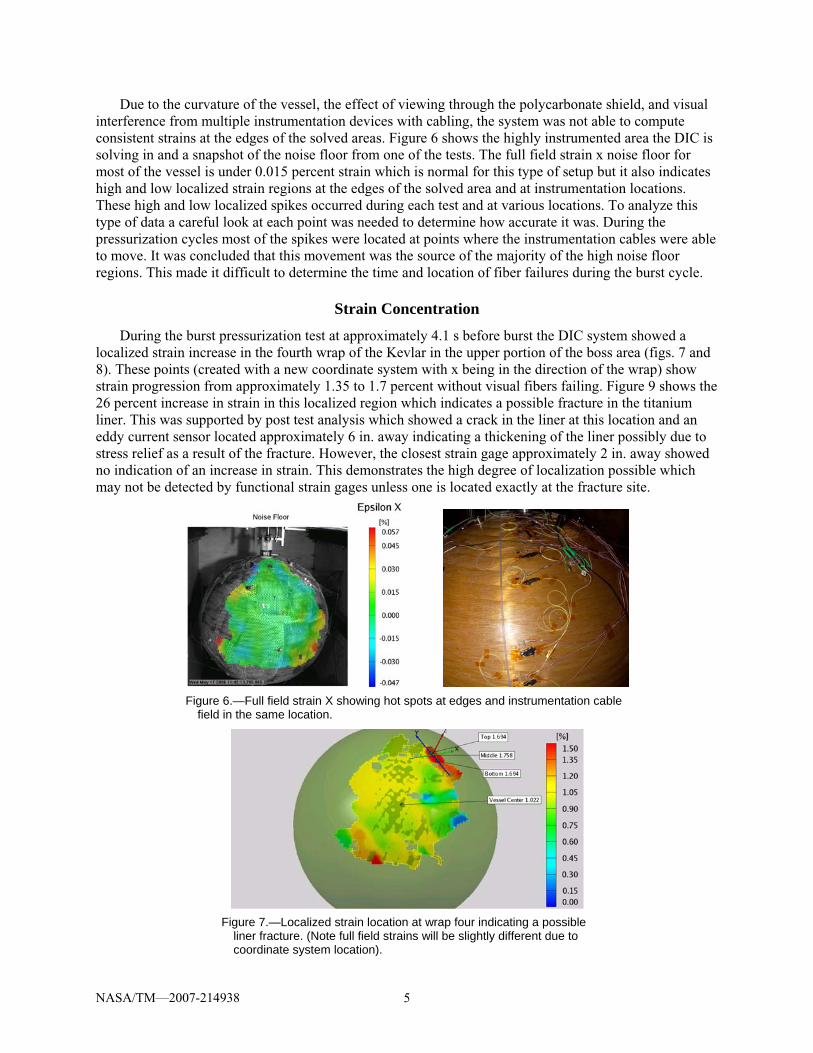
Due to the curvature of the vessel, the effect of viewing through the polycarbonate shield, and visual interference from multiple instrumentation devices with cabling, the system was not able to compute consistent strains at the edges of the solved areas. Figure 6 shows the highly instrumented area the DIC is solving in and a snapshot of the noise floor from one of the tests. The full field strain x noise floor for most of the vessel is under 0.015 percent strain which is normal for this type of setup but it also indicates high and low localized strain regions at the edges of the solved area and at instrumentation locations. These high and low localized spikes occurred during each test and at various locations. To analyze this type of data a careful look at each point was needed to determine how accurate it was. During the pressurization cycles most of the spikes were located at points where the instrumentation cables were able to move. It was concluded that this movement was the source of the majority of the high noise floor regions. This made it difficult to determine the time and location of fiber failures during the burst cycle.
Strain Concentration
During the burst pressurization test at approximately 4.1 s before burst the DIC system showed a localized strain increase in the fourth wrap of the Kevlar in the upper portion of the boss area (figs. 7 and 8). These points (created with a new coordinate system with x being in the direction of the wrap) show strain progression from approximately 1.35 to 1.7 percent without visual fibers failing. Figure 9 shows the 26 percent increase in strain in this localized region which indicates a possible fracture in the titanium liner. This was supported by post test analysis which showed a crack in the liner at this location and an eddy current sensor located approximately 6 in. away indicating a thickening of the liner possibly due to stress relief as a result of the fracture. However, the closest strain gage approximately 2 in. away showed no indication of an increase in strain. This demonstrates the high degree of localization possible which may not be detected by functional strain gages unless one is located exactly at the fracture site.
Figure 6.—Full field strain X showing hot spots at edges and instrumentation cable field in the same location.
Figure 7.—Localized strain location at wrap four indicating a possible liner fracture. (Note full field strains will be slightly different due to coordinate system location).

NASA/TM—2007-214938 6
Burst0.00
0.20
0.40
0.60
0.80
1.00
1.20
1.40
1.60
1.80
2.00
-5.5 -4.5 -3.5 -2.5 -1.5 -0.5
Seconds Before Burst
Stra
in X
%
Vessel Center
Middle
Top
Bottom
Figure 8.—Localized Point Strain Increase in Wrap Four Compared to Vessel Center.
(Due to curved surface each point is created with a new coordinate system).
0.80
1.00
1.20
1.40
1.60
1.80
2.00
-4.5 -4 -3.5
Seconds Before Burst
Stra
in X
%
Top
Middle
Bottom
Vessel Center
Figure 9.—Close up view indicating strain increase from top to bottom of wrap four.
Figures 8 and 9 also show more noise in the outer edges of the solved area than in the central region which is believed to be caused by the high viewing angle of the cameras to the curved surface and viewing through the polycarbonate shield. Even with this high noise the system is capable of showing trends of the strain increase. The system was also able to detect decreases in strain at the locations of fiber failure as the vessel approached burst. Figure 10 shows an example of a fiber failure during the burst test. The high speed video that supported the DIC system became very useful in visualizing the fiber breakage and matching it with the strain map to insure the data was not noise in the system.
Principal Strain Growth
Since the mounted gages could only provide strains in the hoop direction of the fiber wrap the DIC system became a valuable tool for measuring the principal strains. Figure 11 shows the principal strain noise floor for the DIC system indicating high noise up to 87 percent at the edges of the solved area and a strain offset of 30 to 40 percent closer in covering about 70 percent of the circumference.

NASA/TM—2007-214938 7
Figure 10.—Low strain reading in the blue area indicates fiber breakage.
Figure 12.—Full field principal strain increase of the vessel during burst test.
This higher strain offset around the edges of the vessel is common for curved objects during similar tests and is generated by the high viewing angle of the cameras to the curved surface and by viewing through the polycarbonate shield. The data in the offset area consistently shows higher values but still is able to determine trends. Figure 12 shows a sequence of graphs of the principal strain during the burst test. The graphs indicate an increase in strain progressing from the right to the left with magnitudes above 2 percent which permeates past the offset area. This is consistent with post test analysis which showed that the vessel failed on the right side. Overall the DIC showed an increasing trend of principal strains on the right side of the vessel that mounted gages were unable to provide since they were only mounted in the one direction.
Conclusion Two digital image correlation systems successfully provided accurate measurements of strain in a
COPV during multiple pressurization tests which helped in the understanding of its complex mechanical
Figure 11.—Full field principal strain noise floor.

NASA/TM—2007-214938 8
response during pressurization. Due to obtaining a large field of view and viewing through a polycarbonate shield a careful analysis was conducted to determine the validity of each area processed. Key results have shown a small increase in strain by viewing through a multi layered polycarbonate shield, an area showing a localized strain increase indicating a possible liner fracture, and a large growth in the principal strain during the burst test which mounted gages were not able to detect.
References 1. Johns, R.H. and A. Kaufman. 1966. Filament-Overwrapped Metallic Cylindrical Pressure Vessels, in
AIAA/ASME Seventh Structures and Materials Conference, AIAA, 52–63. 2. Lark, R.F. 1973. “Filament-wound Composite Vessel Materials Technology,” NASA TMX–68196. 3. Lark, R.F., 1977. “Recent Advances in Lightweight, Filament-wound Composite Pressure Vessel
Technology,” NASA TM 73699. 4. Faddoul, J.R. “Structural Considerations in Design of Lightweight Glass–Fiber Composite Pressure
Vessels,” in Proceedings of the Second International Conference on Pressure Vessel Technology. Part I–Design and Analysis, ASME, 561–572, 1973.
5. Landes, R.E. 1973 “Glass Fiber Reinforced Metal Pressure Vessel Design Guide,” NASA CR-120917, Structural Composites Industries, Inc.
6. Ecord, G.M. “Filament wound pressure vessels with load sharing liners for Space Shuttle Orbiter applications” National Symposium and Exhibition on Bicentennial of Materials Progress, Los Angeles, CA, April 6–8, 1976, Jan. 1, 1976.
7. Landes, R.E. 1976. “Filament–Reinforced Metal Composite Pressure Vessel Evaluation and Performance Demonstration” Structural Composites Industries, Inc. Report SCI-75154, also NASA CR-134975.
8. Schmidt, W.W. and Ecord, G.M. “Static fatigue life of Kevlar aramid/epoxy pressure vessels at room and elevated temperatures,” AIAA PAPER 83-1328; June 1, 1983.
9. NESC Composite Overwrapped Pressure Vessel Independent Technical Assessment Final Report (in preparation).
10. J.M. Pereira, M. Melis, and D. Revilock Jr., “A Summary of the Space Shuttle Columbia Tragedy and the Use of Digital High Speed Photography in the Accident Investigation and NASA’s Return-to-Flight Effort,” SPIE 26th ICHSPP, Sept. 2004.
11. T. Schmidt, J. Tyson, D.M. Revilock Jr., J.M. Pereira, S. Padula II, M. Melis “Performance Verification of 3D Image Correlation Using High-Speed Cameras”. SEM 2005.
12. D. Revilock Jr., M. Melis, T. Schmidt, J. Tyson, K Galanulisb, “Full-field dynamic deformation and strain measurements using high-speed digital cameras”. SPIE 26th ICHSPP, Sept. 2004.

REPORT DOCUMENTATION PAGE Form Approved OMB No. 0704-0188
The public reporting burden for this collection of information is estimated to average 1 hour per response, including the time for reviewing instructions, searching existing data sources, gathering and maintaining the data needed, and completing and reviewing the collection of information. Send comments regarding this burden estimate or any other aspect of this collection of information, including suggestions for reducing this burden, to Department of Defense, Washington Headquarters Services, Directorate for Information Operations and Reports (0704-0188), 1215 Jefferson Davis Highway, Suite 1204, Arlington, VA 22202-4302. Respondents should be aware that notwithstanding any other provision of law, no person shall be subject to any penalty for failing to comply with a collection of information if it does not display a currently valid OMB control number. PLEASE DO NOT RETURN YOUR FORM TO THE ABOVE ADDRESS. 1. REPORT DATE (DD-MM-YYYY) 01-08-2007
2. REPORT TYPE Technical Memorandum
3. DATES COVERED (From - To)
4. TITLE AND SUBTITLE Three-Dimensional Digital Image Correlation of a Composite Overwrapped Pressure Vessel During Hydrostatic Pressure Tests
5a. CONTRACT NUMBER
5b. GRANT NUMBER
5c. PROGRAM ELEMENT NUMBER
6. AUTHOR(S) Revilock, Duane, M, Jr.; Thesken, John, C.; Schmidt, Timothy, E.; Forsythe, Bradley, S.
5d. PROJECT NUMBER
5e. TASK NUMBER
5f. WORK UNIT NUMBER WBS 377816.06.03.02.10
7. PERFORMING ORGANIZATION NAME(S) AND ADDRESS(ES) National Aeronautics and Space Administration John H. Glenn Research Center at Lewis Field Cleveland, Ohio 44135-3191
8. PERFORMING ORGANIZATION REPORT NUMBER E-16172
9. SPONSORING/MONITORING AGENCY NAME(S) AND ADDRESS(ES) National Aeronautics and Space Administration Washington, DC 20546-0001
10. SPONSORING/MONITORS ACRONYM(S) NASA
11. SPONSORING/MONITORING REPORT NUMBER NASA/TM-2007-214938
12. DISTRIBUTION/AVAILABILITY STATEMENT Unclassified-Unlimited Subject Categories: 18, 39, and 15 Available electronically at http://gltrs.grc.nasa.gov This publication is available from the NASA Center for AeroSpace Information, 301-621-0390
13. SUPPLEMENTARY NOTES
14. ABSTRACT Ambient temperature hydrostatic pressurization tests were conducted on a composite overwrapped pressure vessel (COPV) to understand the fiber stresses in COPV components. Two three-dimensional digital image correlation systems with high speed cameras were used in the evaluation to provide full field displacement and strain data for each pressurization test. A few of the key findings will be discussed including how the principal strains provided better insight into system behavior than traditional gauges, a high localized strain that was measured where gages were not present and the challenges of measuring curved surfaces with the use of a 1.25 in. thick layered polycarbonate panel that protected the cameras. 15. SUBJECT TERMS Pressure vessels; Burst testing; Image correlation; Fiber composites; Composite wrapping
16. SECURITY CLASSIFICATION OF: 17. LIMITATION OF ABSTRACT UU
18. NUMBER OF PAGES
14
19a. NAME OF RESPONSIBLE PERSON STI Help Desk (email:[email protected])
a. REPORT U
b. ABSTRACT U
c. THIS PAGE U
19b. TELEPHONE NUMBER (include area code) 301-621-0390
Standard Form 298 (Rev. 8-98)Prescribed by ANSI Std. Z39-18

