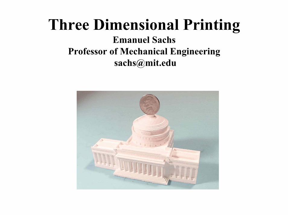
three dimensional printing - dtic.mil three dimensional printing emanuel sachs professor of...
TRANSCRIPT

REPORT DOCUMENTATION PAGE Form Approved OMB No.0704-0188
Public reporting burder for this collection of information is estibated to average 1 hour per response, including the time for reviewing instructions, searching existing data sources, gathering and maintaining the data needed, and completingand reviewing this collection of information. Send comments regarding this burden estimate or any other aspect of this collection of information, including suggestions for reducing this burder to Department of Defense, WashingtonHeadquarters Services, Directorate for Information Operations and Reports (0704-0188), 1215 Jefferson Davis Highway, Suite 1204, Arlington, VA 22202-4302. Respondents should be aware that notwithstanding any other provision oflaw, no person shall be subject to any penalty for failing to comply with a collection of information if it does not display a currently valid OMB control number. PLEASE DO NOT RETURN YOUR FORM TO THE ABOVE ADDRESS.
1. REPORT DATE (DD-MM-YYYY)30-05-2001
2. REPORT TYPEWorkshop Presentations
3. DATES COVERED (FROM - TO)30-05-2001 to 01-06-2001
4. TITLE AND SUBTITLEThree Dimensional PrintingUnclassified
5a. CONTRACT NUMBER5b. GRANT NUMBER5c. PROGRAM ELEMENT NUMBER
6. AUTHOR(S)Sachs, Emanuel ;
5d. PROJECT NUMBER5e. TASK NUMBER5f. WORK UNIT NUMBER
7. PERFORMING ORGANIZATION NAME AND ADDRESSMITxxxxx, MAxxxxx
8. PERFORMING ORGANIZATION REPORTNUMBER
9. SPONSORING/MONITORING AGENCY NAME AND ADDRESSOffice of Naval Research International Field OfficeOffice of Naval ResearchWashington, DCxxxxx
10. SPONSOR/MONITOR'S ACRONYM(S)11. SPONSOR/MONITOR'S REPORTNUMBER(S)
12. DISTRIBUTION/AVAILABILITY STATEMENTAPUBLIC RELEASE,13. SUPPLEMENTARY NOTESSee Also ADM001348, Thermal Materials Workshop 2001, held in Cambridge, UK on May 30-June 1, 2001. Additional papers can bedownloaded from: http://www-mech.eng.cam.ac.uk/onr/14. ABSTRACT3D Printing is an SFF Process which creates parts in layers. Each layer is formed by spreading powder and selectively joining the powder byink-jet printing of a binder material.15. SUBJECT TERMS16. SECURITY CLASSIFICATION OF: 17. LIMITATION
OF ABSTRACTPublic Release
18.NUMBEROF PAGES38
19. NAME OF RESPONSIBLE PERSONFenster, [email protected]
a. REPORTUnclassified
b. ABSTRACTUnclassified
c. THIS PAGEUnclassified
19b. TELEPHONE NUMBERInternational Area CodeArea Code Telephone Number703767-9007DSN427-9007
Standard Form 298 (Rev. 8-98)Prescribed by ANSI Std Z39.18
3DPTM Team
FACULTY
Emanuel Sachs
Michael Cima
Samuel Allen
Nick Patrikalakis
Linda Griffith
GRADUATE STUDENTSDavid AblesRené ApitzDiana ButtzDavid GuoRichard HolmanSang-bum HongHongye LiuAdam LorenzMark OliveiraChilukuri RamStephen SmythScott UhlandMarkus WernerCalvin Yuen
RESEARCH STAFF
James Serdy
Chris Stratton
Benjamin Polito
Post-Docs andVisitors
Hiroyasu Tsuchiya
Yasushi Enokido
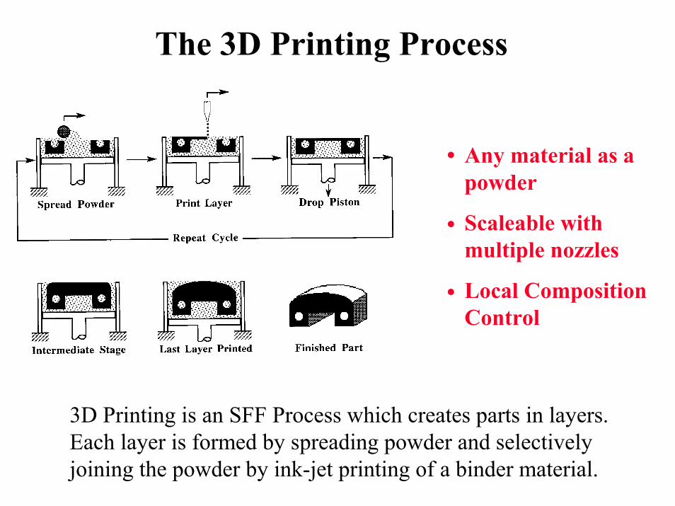
The 3D Printing Process
Any material as apowder
Scaleable withmultiple nozzles
Local CompositionControl
3D Printing is an SFF Process which creates parts in layers.Each layer is formed by spreading powder and selectivelyjoining the powder by ink-jet printing of a binder material.
•
•
•
mmm. li
Spread Powder Print Layer
wmm u
Drop Piston
Repeat Cycle
W/, Ld Wfc Intermediate Stage
W%. Ld ^ Last Layer Printed Finished Part
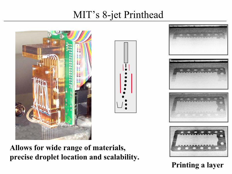
MIT’s 8-jet Printhead
Allows for wide range of materials,precise droplet location and scalability.
Printing a layer
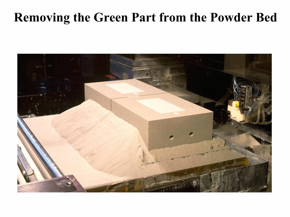
Removing the Green Part from the Powder Bed
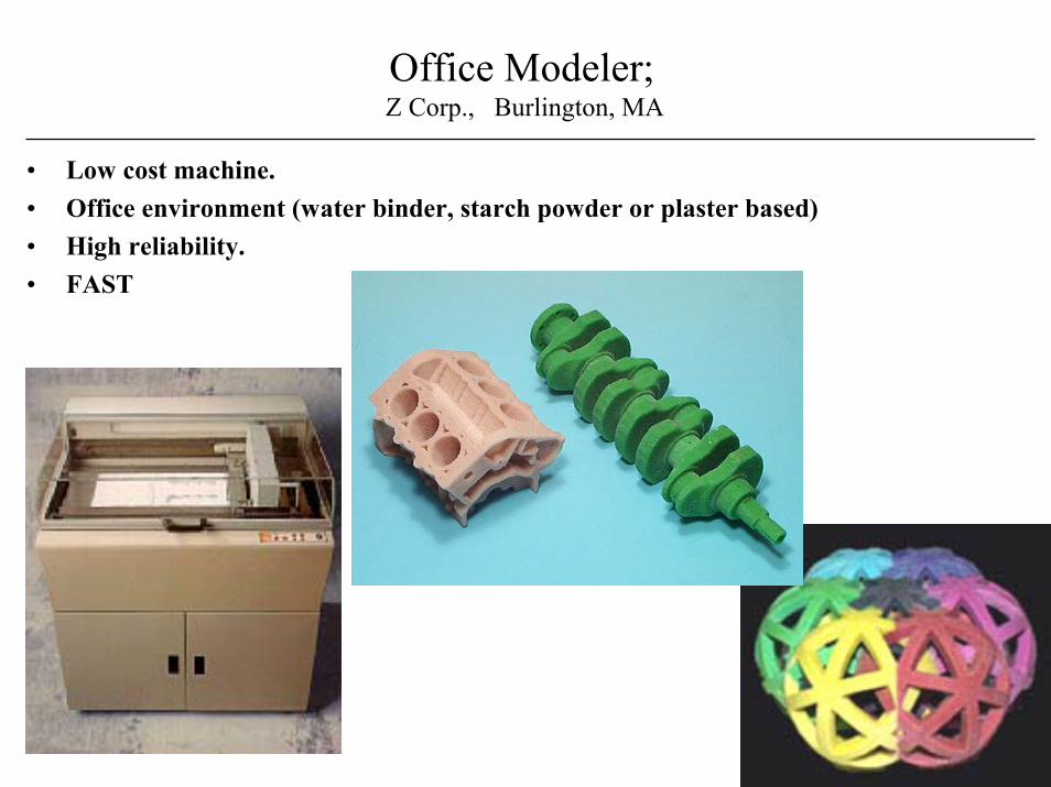
Office Modeler; Z Corp., Burlington, MA
• Low cost machine.• Office environment (water binder, starch powder or plaster based)• High reliability.• FAST
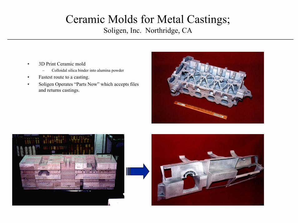
Ceramic Molds for Metal Castings;Soligen, Inc. Northridge, CA
• 3D Print Ceramic mold– Colloidal silica binder into alumina powder
• Fastest route to a casting.• Soligen Operates “Parts Now” which accepts files
and returns castings.
* It 1
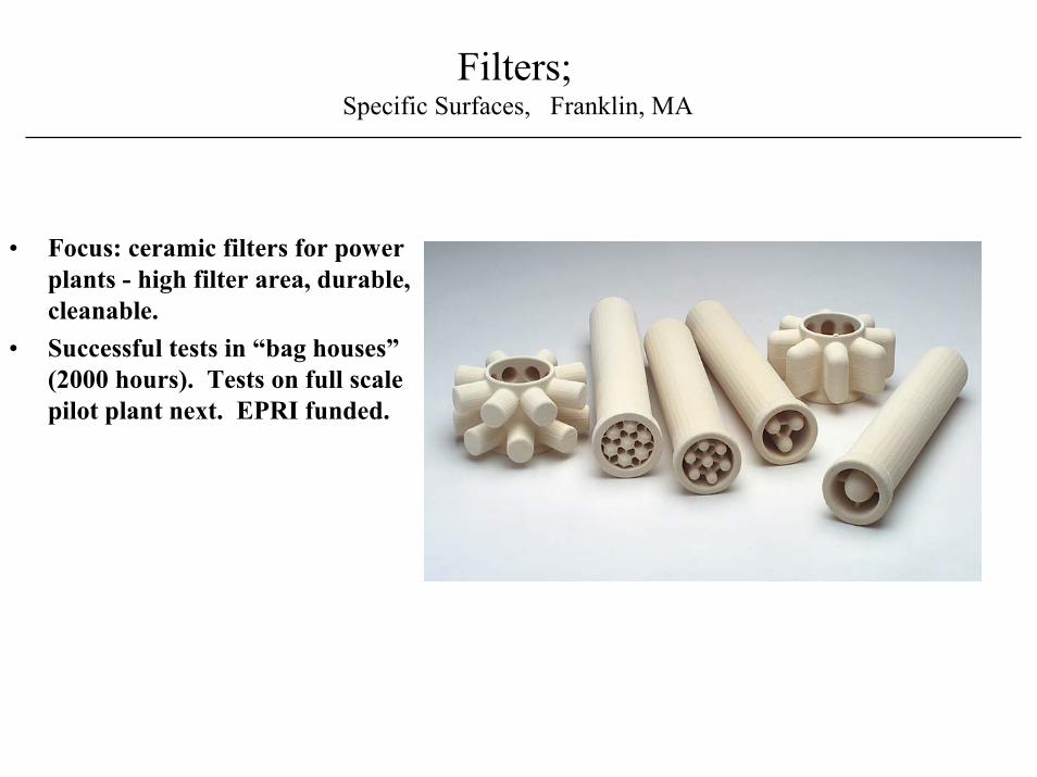
Filters; Specific Surfaces, Franklin, MA
• Focus: ceramic filters for powerplants - high filter area, durable,cleanable.
• Successful tests in “bag houses”(2000 hours). Tests on full scalepilot plant next. EPRI funded.
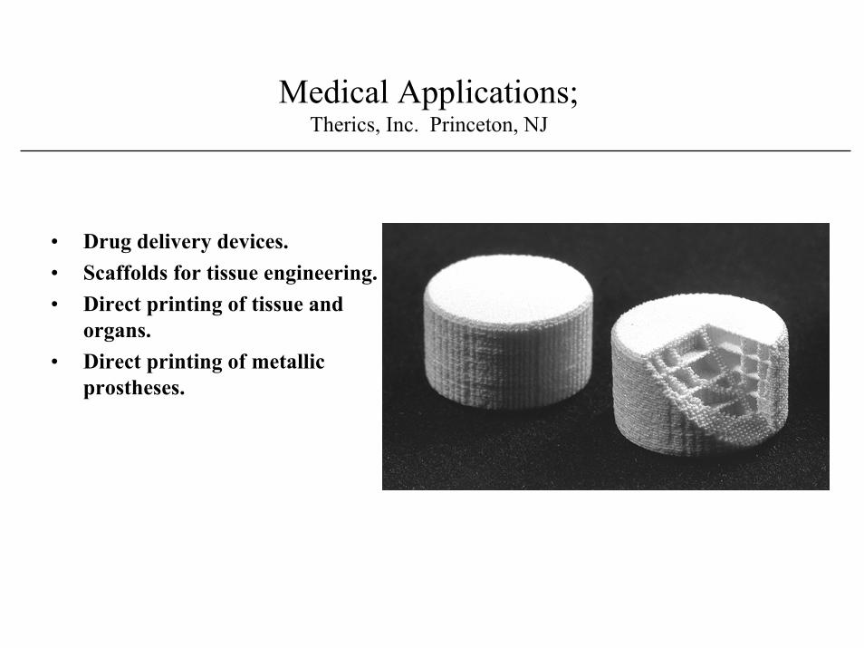
Medical Applications;Therics, Inc. Princeton, NJ
• Drug delivery devices.• Scaffolds for tissue engineering.• Direct printing of tissue and
organs.• Direct printing of metallic
prostheses.
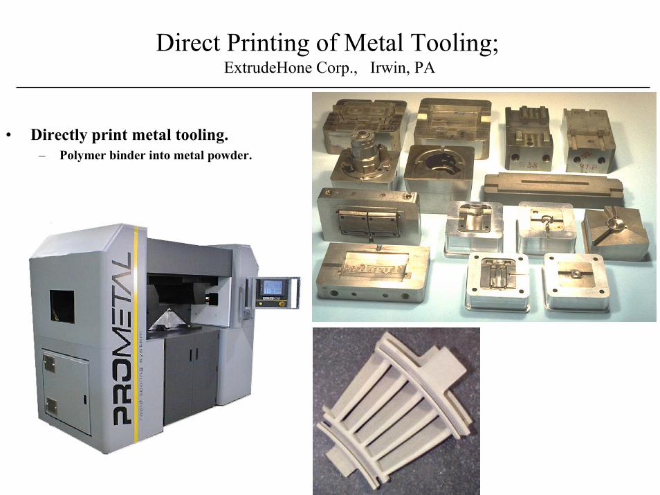
Direct Printing of Metal Tooling; ExtrudeHone Corp., Irwin, PA
• Directly print metal tooling.– Polymer binder into metal powder.
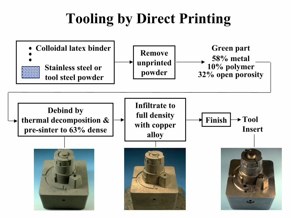
Tooling by Direct Printing
Colloidal latex binder
Stainless steel or tool steel powder
Removeunprinted
powder
Green part58% metal
10% polymer32% open porosity
Debind bythermal decomposition &pre-sinter to 63% dense
Infiltrate tofull densitywith copper
alloy
Finish ToolInsert
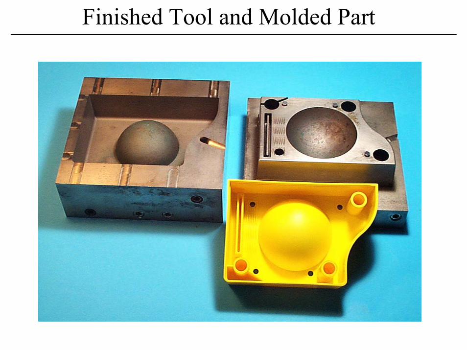
Finished Tool and Molded Part
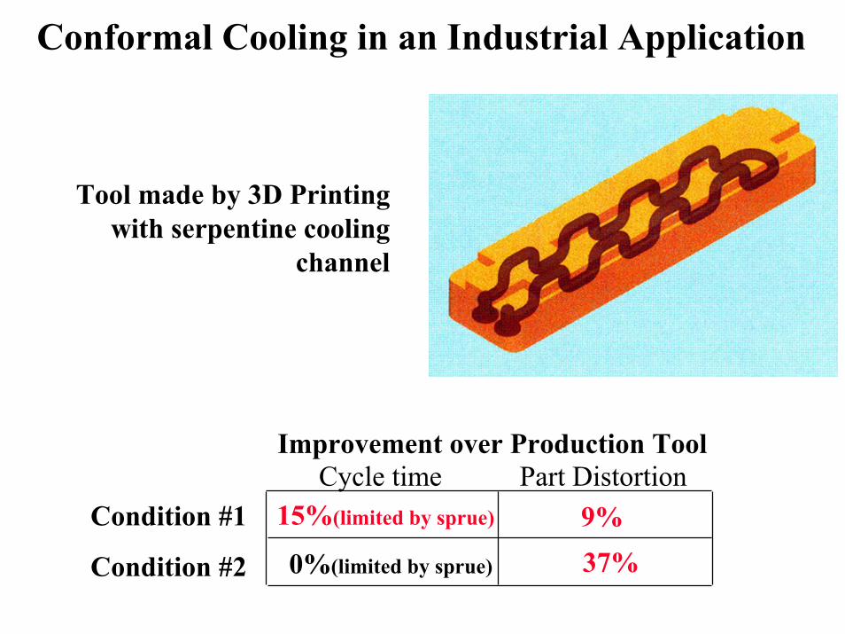
Conformal Cooling in an Industrial Application
Improvement over Production ToolCycle time Part Distortion
Condition #1
Condition #2
Tool made by 3D Printingwith serpentine cooling
channel
15%(limited by sprue) 9%37% 0%(limited by sprue)
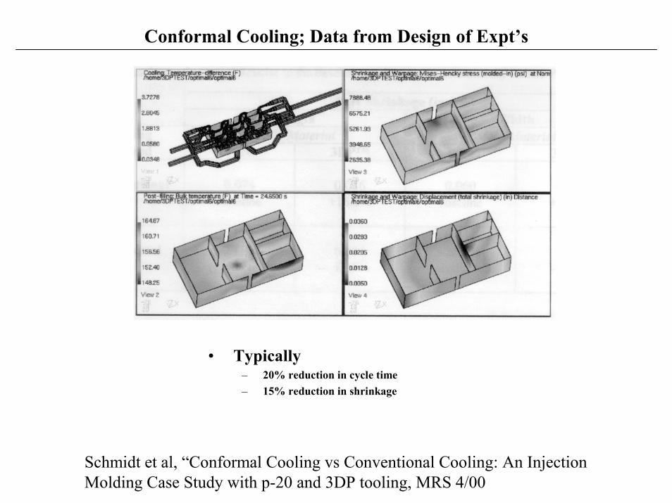
Conformal Cooling; Data from Design of Expt’s
• Typically– 20% reduction in cycle time– 15% reduction in shrinkage
Schmidt et al, “Conformal Cooling vs Conventional Cooling: An InjectionMolding Case Study with p-20 and 3DP tooling, MRS 4/00
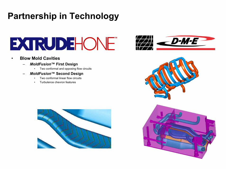
Partnership in Technology
• Blow Mold Cavities– MoldFusion™ First Design
• Two conformal and opposing flow circuits
– MoldFusion™ Second Design• Two conformal linear flow circuits• Turbulence chevron features
EXIRUDEHONE

Demonstration of Performance:Conformal Cooling
0
10
20
30
40
50
60
70
0 60 120 180 240
Time (sec)
Tem
pera
ture
(C)

Conformal Cooling Condition
T ime [se c]
Tem p erature[degC]
si mul ati on d ataexperi men tal dat a
25
20
15
10
5
0300 60 90
Mold ( k, �, c)
One coolingcell
Adjacentcooling cell
coolant
plastic
L
Lk
< Cycle Time� c
2

Conformal Cooling ChannelDesign Methodology
• Design for conformal cooling• Design for sufficient cooling• Design for temperature drop• Design for cooling uniformity• Design for pressure drop• Design for mold strength & deflection
before design part
cooling zone 2
cooling zone 1
after design
Map to entiremold
Map to entiremold
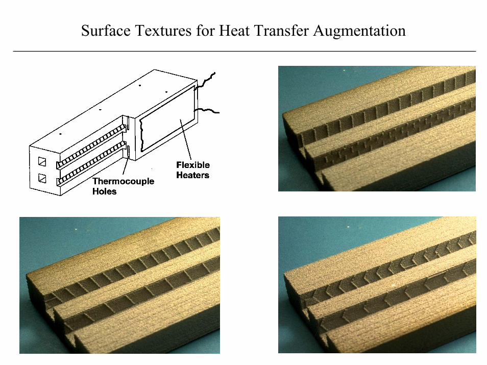
Surface Textures for Heat Transfer Augmentation
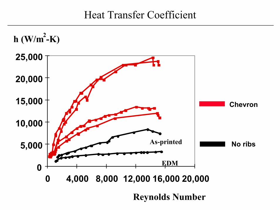
0
5,000
10,000
15,000
20,000
25,000
0 4,000 8,000 12,000 16,000 20,000
Heat Transfer Coefficient
No ribs
Chevron
h (W/m -K)2
Reynolds Number
EDM
As-printed
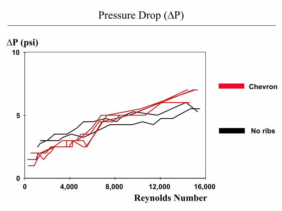
0
5
10
0 4,000 8,000 12,000 16,000
Pressure Drop (�P)
No ribs
Chevron
�P (psi)
Reynolds Number
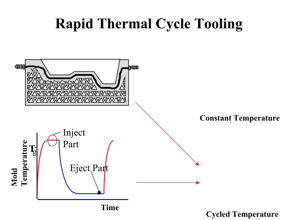
Rapid Thermal Cycle Tooling
Time
Mol
dT
empe
ratu
re T
InjectPart
Eject Part
g
Constant Temperature
Cycled Temperature

3D Printed Tool for Rapid Thermal Cycling
The tool has cooling/heating channels in the top plate and stands on 2000 posts(which allow for thermal expansion/contraction)
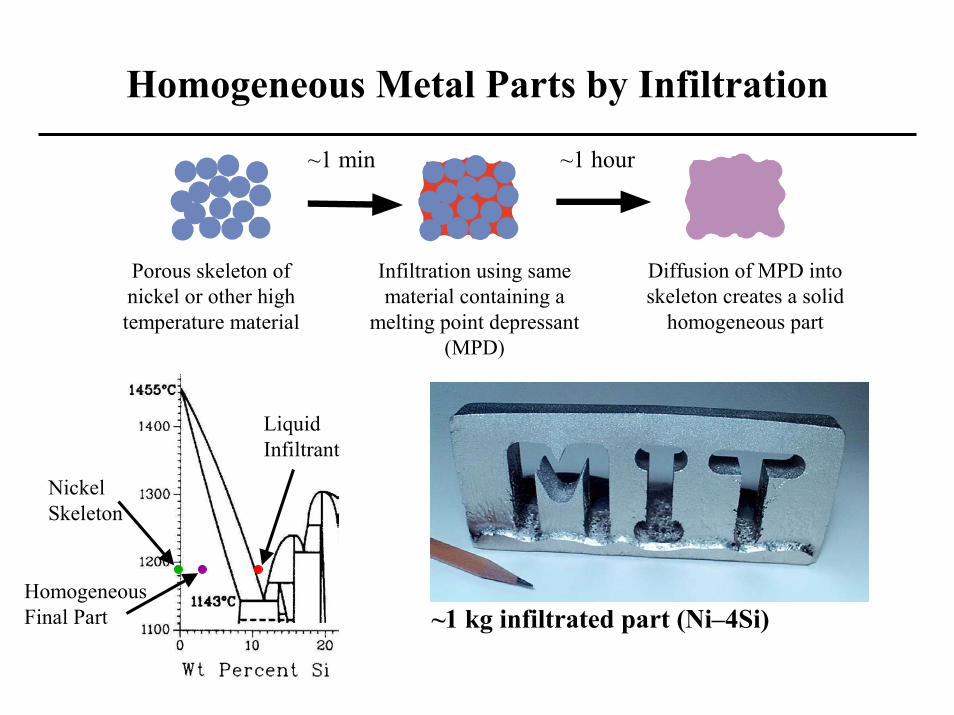
Homogeneous Metal Parts by Infiltration
Porous skeleton ofnickel or other hightemperature material
Infiltration using samematerial containing a
melting point depressant(MPD)
Diffusion of MPD intoskeleton creates a solid
homogeneous part
~1 min ~1 hour
Liquid Infiltrant
NickelSkeleton
HomogeneousFinal Part ~1 kg infiltrated part (Ni–4Si)
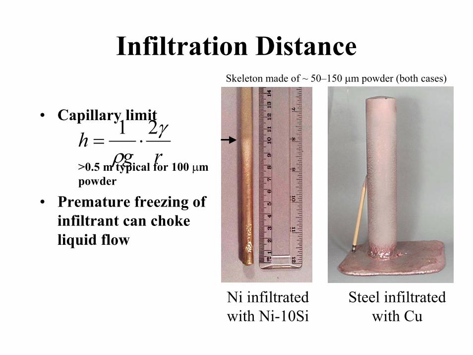
Infiltration Distance
• Capillary limit
>0.5 m typical for 100 �mpowder
• Premature freezing ofinfiltrant can chokeliquid flow
Steel infiltratedwith Cu
Ni infiltratedwith Ni-10Si
rgh �
�
21��
Skeleton made of ~ 50–150 �m powder (both cases)

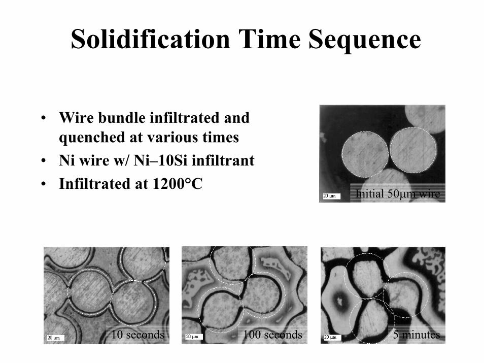
Solidification Time Sequence
5 minutes100 seconds10 seconds
Initial 50�m wire
• Wire bundle infiltrated andquenched at various times
• Ni wire w/ Ni–10Si infiltrant• Infiltrated at 1200°C
Solidification Time Sequence
5 minutes100 seconds10 seconds
Initial 50�m wire
• Wire bundle infiltrated andquenched at various times
• Ni wire w/ Ni–10Si infiltrant• Infiltrated at 1200°C
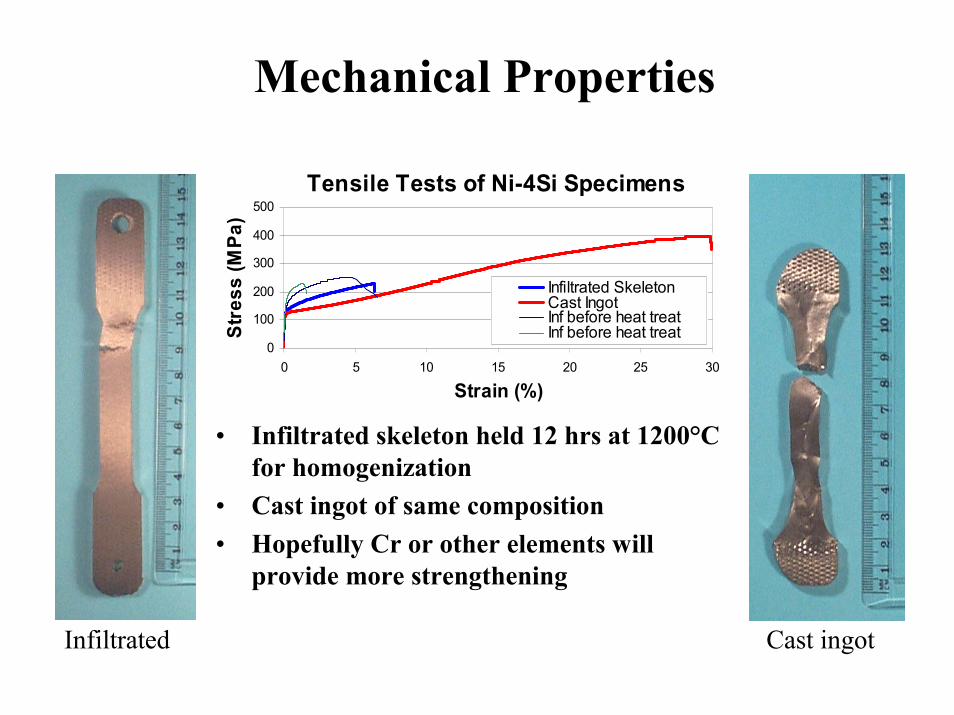
Mechanical Properties
• Infiltrated skeleton held 12 hrs at 1200°Cfor homogenization
• Cast ingot of same composition• Hopefully Cr or other elements will
provide more strengthening
Tensile Tests of Ni-4Si Specimens
0
100
200
300
400
500
0 5 10 15 20 25 30
Strain (%)
Stre
ss (M
Pa)
Infiltrated SkeletonCast IngotInf before heat treatInf before heat treat
Infiltrated Cast ingot
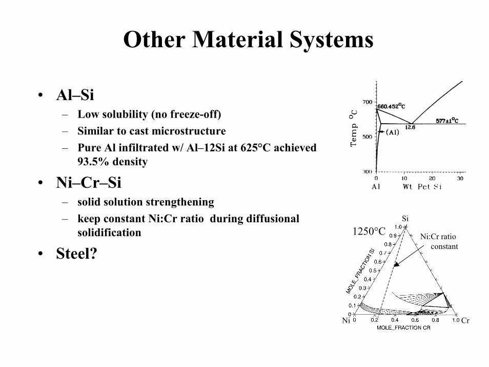
Other Material Systems
• Al–Si– Low solubility (no freeze-off)– Similar to cast microstructure– Pure Al infiltrated w/ Al–12Si at 625°C achieved
93.5% density
• Ni–Cr–Si– solid solution strengthening– keep constant Ni:Cr ratio during diffusional
solidification
• Steel?Ni:Cr ratio
constant
Ni Cr
Si
1250°C
0.2 0.4 0.6 0.8 MOLE_FRACTION CR
1.0
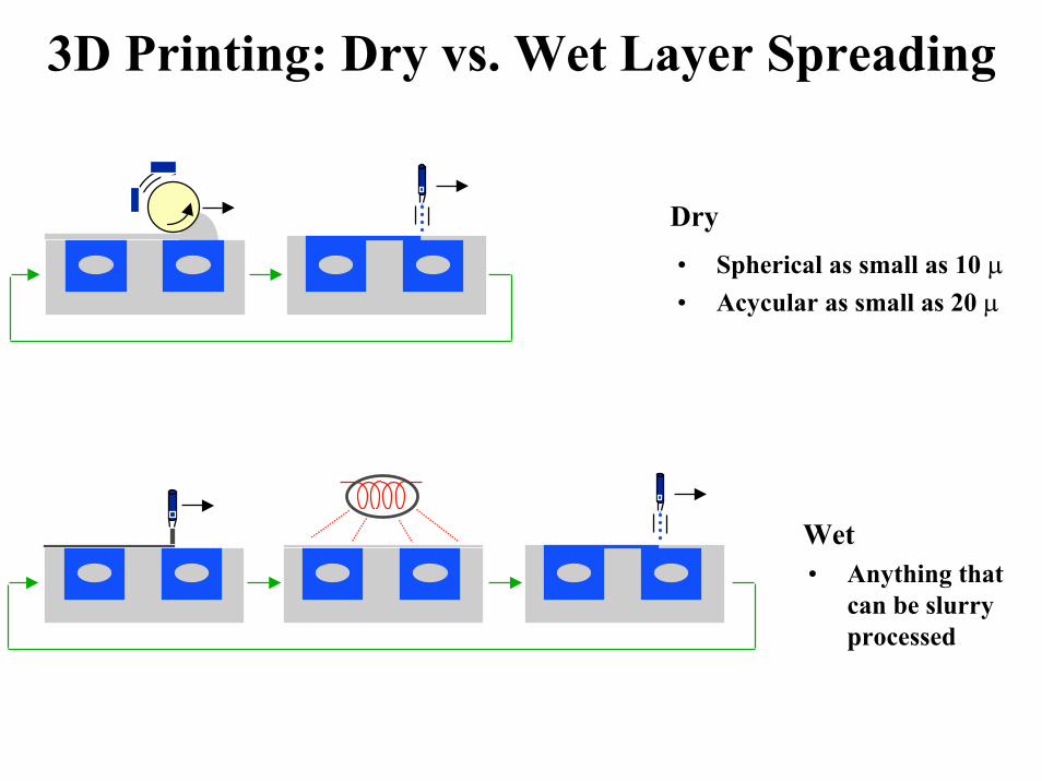
3D Printing: Dry vs. Wet Layer Spreading
• Anything thatcan be slurryprocessed
Dry• Spherical as small as 10 �• Acycular as small as 20 �
Wet
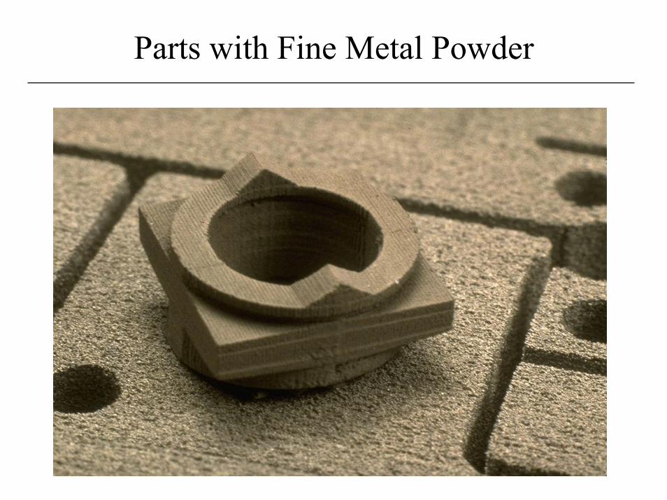
Parts with Fine Metal Powder
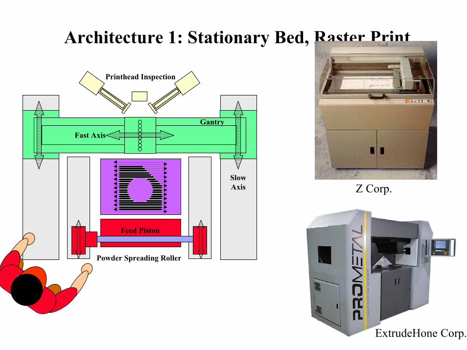
Architecture 1: Stationary Bed, Raster Print
Powder Bed
Feed Piston
Gantry
Fast Axis
SlowAxis
Printhead Inspection
Powder Spreading Roller
Z Corp.
ExtrudeHone Corp.
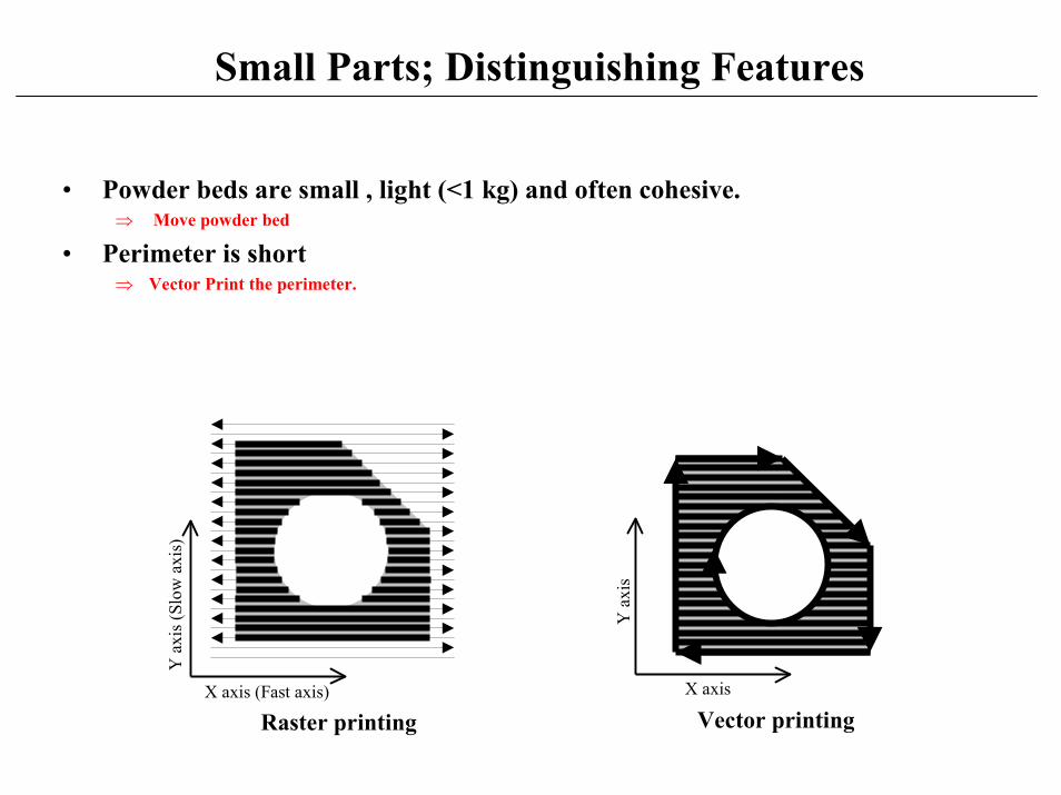
Small Parts; Distinguishing Features
• Powder beds are small , light (<1 kg) and often cohesive.� Move powder bed
• Perimeter is short� Vector Print the perimeter.
Vector printingX axis
Y a
xis
Raster printingX axis (Fast axis)
Y a
xis (
Slow
axi
s)
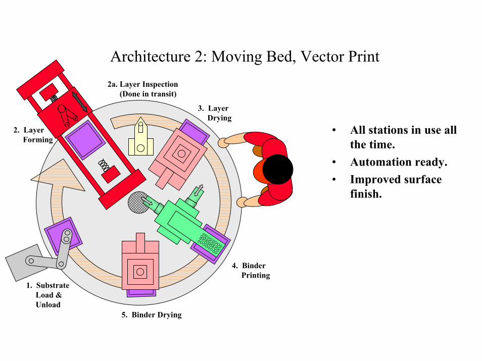
1. SubstrateLoad &Unload
2. LayerForming
2a. Layer Inspection(Done in transit)
3. LayerDrying
4. BinderPrinting
5. Binder Drying
Architecture 2: Moving Bed, Vector Print
• All stations in use allthe time.
• Automation ready.• Improved surface
finish.
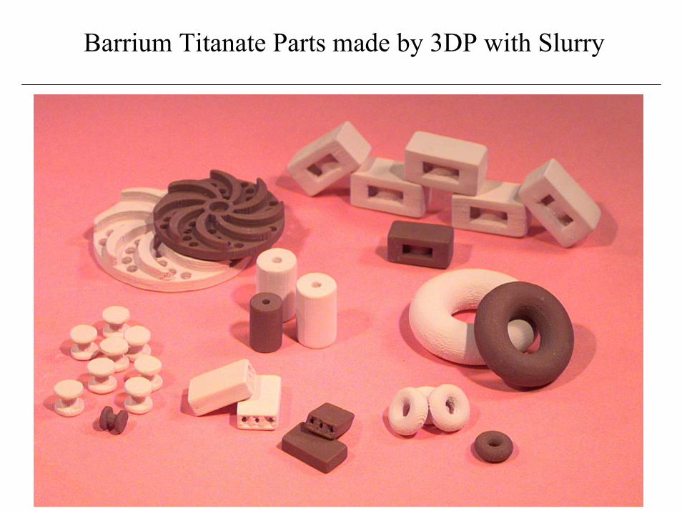
Barrium Titanate Parts made by 3DP with Slurry
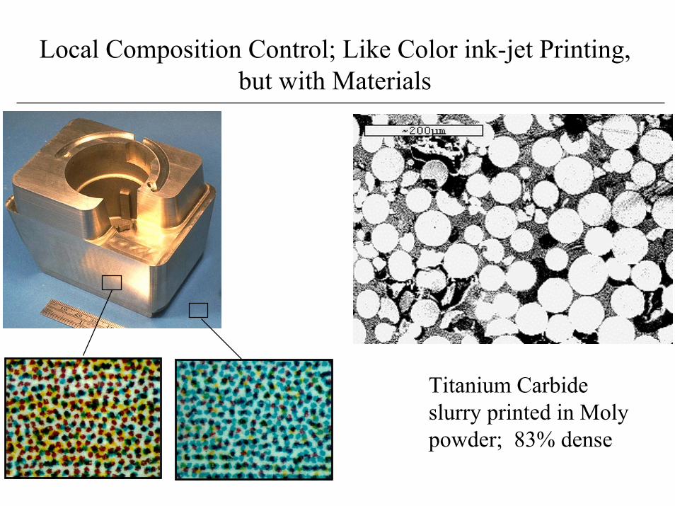
Local Composition Control; Like Color ink-jet Printing,but with Materials
Titanium Carbideslurry printed in Molypowder; 83% dense
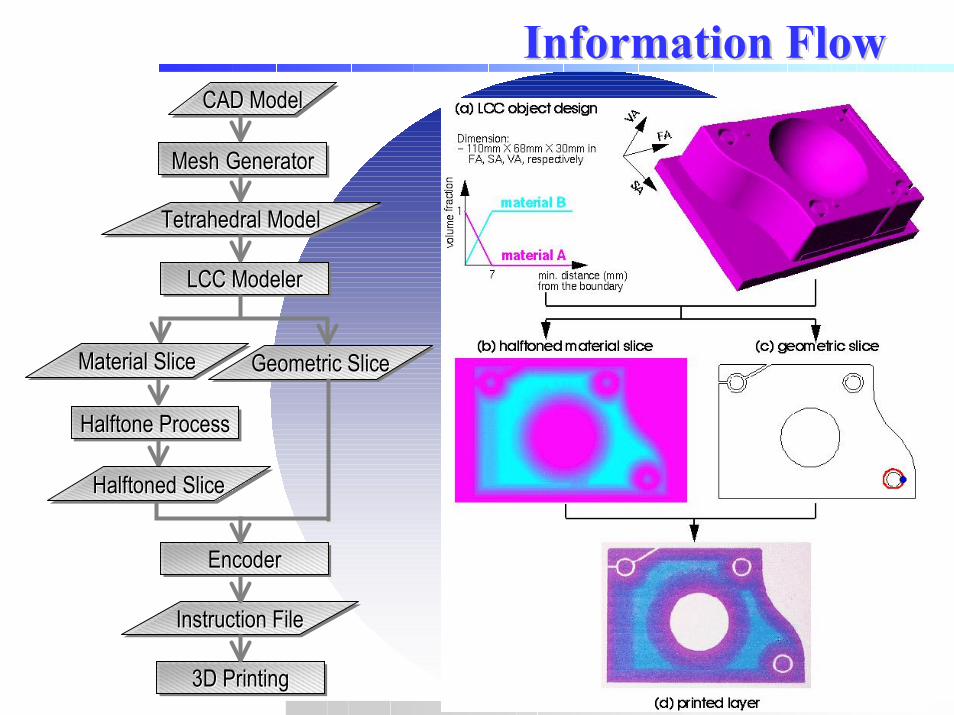
Information FlowInformation FlowCAD ModelCAD ModelCAD Model
Mesh GeneratorMeshMesh GeneratorGenerator
Tetrahedral ModelTetrahedral ModelTetrahedral Model
LCC ModelerLCC ModelerLCC Modeler
Geometric SliceGeometric SliceGeometric Slice
Halftone ProcessHalftone ProcessHalftone Process
EncoderEncoderEncoder
Material SliceMaterial SliceMaterial Slice
Halftoned SliceHalftonedHalftoned Slice Slice
Instruction FileInstruction FileInstruction File
3D Printing3D Printing3D Printing
(a) LCC object design
Dimension: - 110mm X 68mm X 30mm in
FA SA, VA, respectively
(d) printed layer
Summary:3DP for Thermal Management
• Cooling/heating channels - high complexity• Surface textures• Macro cellular structures• Locally controlled porosity• Locally controlled thermal conductivity