ti quick troubleshooting guide (tun-qtsg-0519-en) · quick troubleshooting guide tun-qtsg-0519-en...
TRANSCRIPT
Quick Troubleshooting Guide TUN-QTSG-0519-EN For power inverter models M1500 – M2000 – M2500 – M3000
Tel.: 450.649.2470 / 1.877.964.2582 Fax.: 1.888.855.9834
TUNDRAINVERTERS.COM
TRUCK POWER INVERTERS Quick Troubleshooting Guide For power inverter models M1500 – M2000 – M2500 – M3000
INDEX P.2 INTRODUCTION - SAFETY - LIMITATIONS P.3 FRONT PANELS & MONITORS P.4 ERROR CODES PP.5-6 COMMON PROBLEMS & COMMON CAUSES PP.7-21 PROCEDURES P.22+ ANNEXES © ALL RIGHTS RESERVED No part of this publication may be reproduced or used without the prior written permission of Tundra International. No liability can be accepted for any inaccuracies or omissions in this publication, although every possible care has been taken to make it as complete and accurate as possible. The right is reserved to make changes at any time without prior notice, and without incurring an obligation to make such changes applicable to previously manufactured products. All information contained in this publication is based on the latest product information available at the time of publication. Illustrations and photographs in this publication are intended for reference use only.
TUNDRAINVERTERS.COM May 2019 Part No. TUN-QTSG-0519-EN First Edition PRINTED IN CANADA
1
Quick Troubleshooting Guide TUN-QTSG-0519-EN For power inverter models M1500 – M2000 – M2500 – M3000
Tel.: 450.649.2470 / 1.877.964.2582 Fax.: 1.888.855.9834
TUNDRAINVERTERS.COM
INTRODUCTION This step-by-step troubleshooting guide will help you identify the root cause of the most common problems on power inverters installed in a commercial truck application. This guide is designed to be used primarily by trained mechanics and in a properly equipped shop. A basic knowledge of mechanics and electricity, the proper use of tools and common workshop procedures are required to adequately and safely perform all recommended tasks. For a successful diagnostic, you must read all the instructions thoroughly to familiarize yourself with procedures before starting the work.
SAFETY FIRST A power inverter is an energy conversion device that must be taken seriously. Similar to that produced by a conventional electrical network, its electric current is powerful enough to injure or kill. As such, the inverter should only be installed and serviced by qualified technicians.
A power inverter is an energy conversion device that MUST be taken seriously and MUST be serviced with care.
For your own safety and that of others, make sure you understand all the steps outlined in this manual before servicing.
Do not carry out the tasks of an electrician if you don’t have the knowledge and skills required. Always keep in mind that you can be badly injured working on or around a motor vehicle. Only do service work for which you have the proper knowledge. If you have any doubt
about your ability to perform a maintenance or a repair job, you should not undertake it.
LIMITATIONS The procedures described in this guide are only suggestions and are not mandatory. Therefore, Tundra International cannot be held liable for incidental or consequential damages or any other damage arising from the use of this guide. This includes, without limitation, injuries, damage resulting from loss of use, installation or uninstallation costs, and any other problems.
2
Quick Troubleshooting Guide TUN-QTSG-0519-EN For power inverter models M1500 – M2000 – M2500 – M3000
Tel.: 450.649.2470 / 1.877.964.2582 Fax.: 1.888.855.9834
TUNDRAINVERTERS.COM
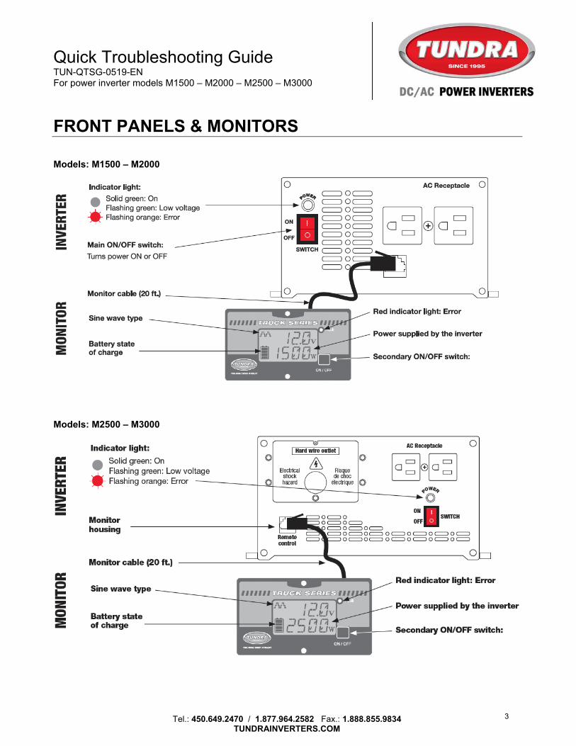
FRONT PANELS & MONITORS Models: M1500 – M2000 Models: M2500 – M3000
3
Quick Troubleshooting Guide TUN-QTSG-0519-EN For power inverter models M1500 – M2000 – M2500 – M3000
Tel.: 450.649.2470 / 1.877.964.2582 Fax.: 1.888.855.9834
TUNDRAINVERTERS.COM
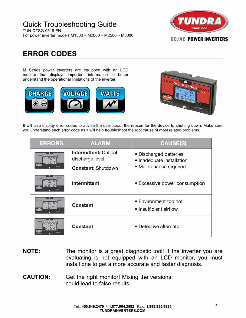
ERROR CODES M Series power inverters are equipped with an LCD monitor that displays important information to better understand the operational limitations of the inverter. It will also display error codes to advise the user about the reason for the device to shutting down. Make sure you understand each error code as it will help troubleshoot the root cause of most related problems.
NOTE: The monitor is a great diagnostic tool! If the inverter you are evaluating is not equipped with an LCD monitor, you must install one to get a more accurate and faster diagnosis.
CAUTION: Get the right monitor! Mixing the versions
could lead to false results.
4
Quick Troubleshooting Guide TUN-QTSG-0519-EN For power inverter models M1500 – M2000 – M2500 – M3000
Tel.: 450.649.2470 / 1.877.964.2582 Fax.: 1.888.855.9834
TUNDRAINVERTERS.COM
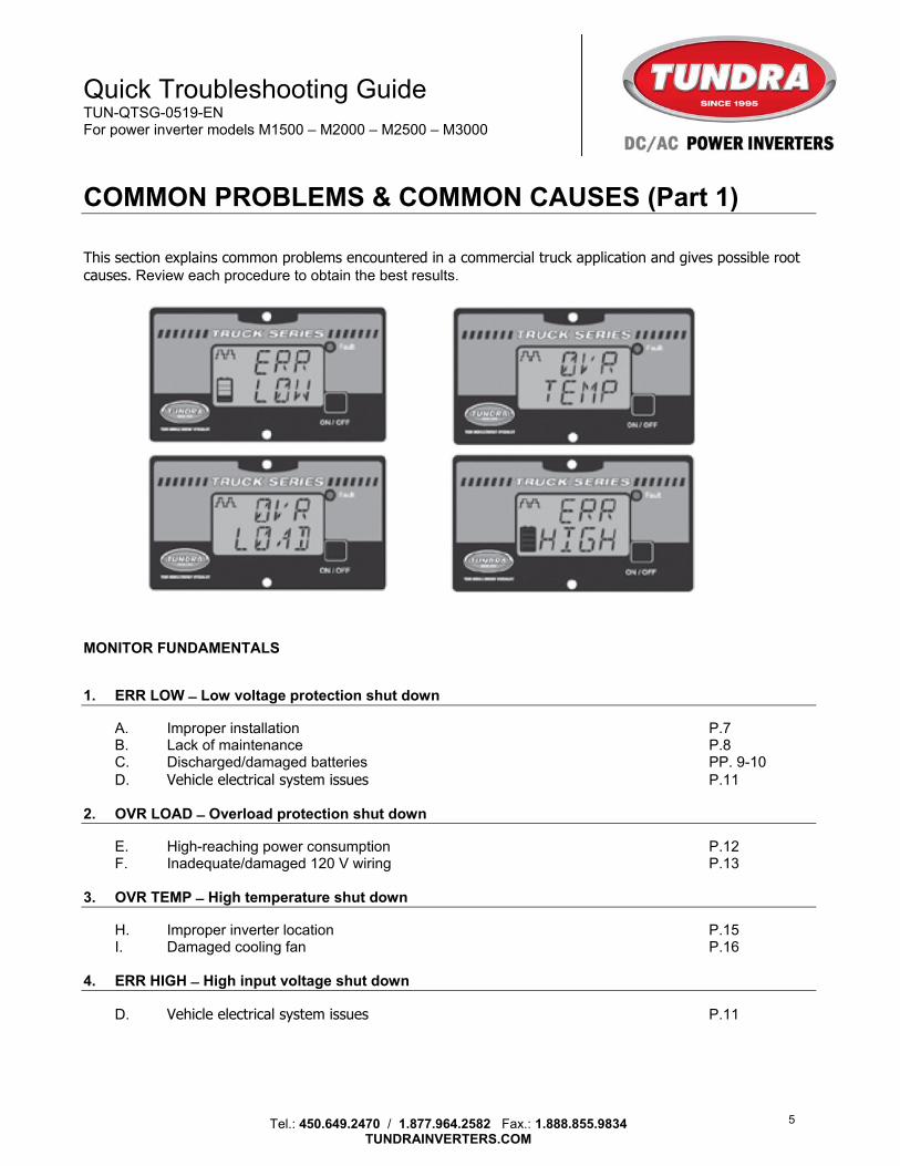
COMMON PROBLEMS & COMMON CAUSES (Part 1) This section explains common problems encountered in a commercial truck application and gives possible root causes. Review each procedure to obtain the best results.
MONITOR FUNDAMENTALS 1. ERR LOW ̶ Low voltage protection shut down
A. Improper installation P.7 B. Lack of maintenance P.8 C. Discharged/damaged batteries PP. 9-10 D. Vehicle electrical system issues P.11
2. OVR LOAD ̶ Overload protection shut down
E. High-reaching power consumption P.12 F. Inadequate/damaged 120 V wiring P.13
3. OVR TEMP ̶ High temperature shut down
H. Improper inverter location P.15 I. Damaged cooling fan P.16
4. ERR HIGH ̶ High input voltage shut down
D. Vehicle electrical system issues P.11
5
Quick Troubleshooting Guide TUN-QTSG-0519-EN For power inverter models M1500 – M2000 – M2500 – M3000
Tel.: 450.649.2470 / 1.877.964.2582 Fax.: 1.888.855.9834
TUNDRAINVERTERS.COM
COMMON PROBLEMS & COMMON CAUSES (Part 2) OTHER COMMON PROBLEM 5. The inverter does not turn on
A. Improper installation P.7 B. Lack of maintenance P.8 J. Reversed polarity P.17 K. Main DC fuse blown (on DC cables) P.18 L. Damaged monitor cable / monitor P.19
6. No output voltage
G. Defective 120V output receptacle P.14 7. Improper output voltage
M. Improper diagnostic tools P.19
8. Noise in audio/video equipment
N. Magnetic field side effects P.20 9. Certain loads are not properly working
O. Modified sine wave limitations P.20 10. Cable size & fuse rating
P. Cable & fuse chart P.21 ANNEXES 1. Dynacraft battery cables modification 2. Testing for parasitic loads 3. Installation workbook
6

Quick Troubleshooting Guide TUN-QTSG-0519-EN For power inverter models M1500 – M2000 – M2500 – M3000
Tel.: 450.649.2470 / 1.877.964.2582 Fax.: 1.888.855.9834
TUNDRAINVERTERS.COM
A – IMPROPER INSTALLATION Improper installation is the most common cause of power inverter malfunction, which often results from impaired flow of current between the batteries and the power inverter. A power inverter operates between 11.0 and 13.6 volts. If the input voltage at the power inverter drops below 11.0 volts, the low voltage protection mode will be activated, and the power inverter will shut OFF by itself. INSTALLATION FUNDAMENTALS 1. Follow installation procedures carefully and use the proper techniques.
References: TDIW-0417-EN / Installation Workbook (ANNEX 3)
QIG1530-0119-EN_A2 / Quick Installation Guide (ANNEX 2) PROCEDURE P / Cable Sizing & Fuse Rating (Page 21)
2. Make sure that all terminals are properly “crimped” and NOT soldered. 3. Make sure the connection at the batteries are clean and in full contact with the battery’s posts. 4. If equipped with Dynacraft battery links, make sure there is full contact between terminals.
Reference: TUN-NL_DYNA-1114-EN / Dynacraft battery cables modification. (ANNEX 1)
5. Perform routine maintenance on batteries and terminals. See PROCEDURE B (Page 8). IF A SMALL LOAD (I.E. 100 W) CAN BE SUPPLIED PROPERLY BUT A GREATER ONE (I.E. 1000 W) IS PUTTING THE INVERTER IN A LOW VOLTAGE PROTECTION MODE, (ERR LOW) YOU SHOULD PERFORM A VOLTAGE LOAD TEST TO DETERMINE IF THE INSTALLATION IS AT FAULT. VOLTAGE DROP TEST PROCEDURE – BATTERIES MUST BE FULLY CHARGED
Try to run the inverter with the greatest possible load. Measure the voltage difference between the batteries and the inverter DC inputs.
This procedure will give you the voltage drop (loss) in the DC cables. A tolerance of 0.5 V is acceptable at full capacity of the power inverter. If you are not at full capacity, and if the voltage drop is greater than 0.5 V, the installation requires attention. BEST PRACTICE Using one of our CM Series Installation Kits is strongly recommended as it will resolve most related issues. For best results, it is important you follow recommended procedures.
RECOMMENDED cable sizing & fuse rating available on page 21
7
Quick Troubleshooting Guide TUN-QTSG-0519-EN For power inverter models M1500 – M2000 – M2500 – M3000
Tel.: 450.649.2470 / 1.877.964.2582 Fax.: 1.888.855.9834
TUNDRAINVERTERS.COM
B – LACK OF MAINTENANCE Battery maintenance on a commercial vehicle is often overlooked. Over time, the various electrical connections tend to loosen, corrode and lose their effectiveness. Battery maintenance should be part of a regular preventive maintenance program to avoid the most common power inverter issues. MAINTENANCE FUNDAMENTALS Today’s battery terminals and connectors that are mostly tinned or zinc plated are therefore less prone to visible corrosion like it used to be with bare copper. On the other hand, they are subject to a chemical reaction that produces a “gum” which will prevent the free flow of electricity over time.
BASIC TERMINAL CLEANING MUST BE PERFORMED EVERY 6 MONTHS. 1. Battery cleaning must be made regularly using a grease dissolvent agent. 2. All battery terminals and accessory cables must be disassembled and cleaned on BOTH faces. 3. All battery terminals must be re-installed DRY. If you intend to use a protective sealant, we
suggest using an aerosol type protectant that "dries” like paint. The protective sealant must only be applied on top of properly tightened connectors.
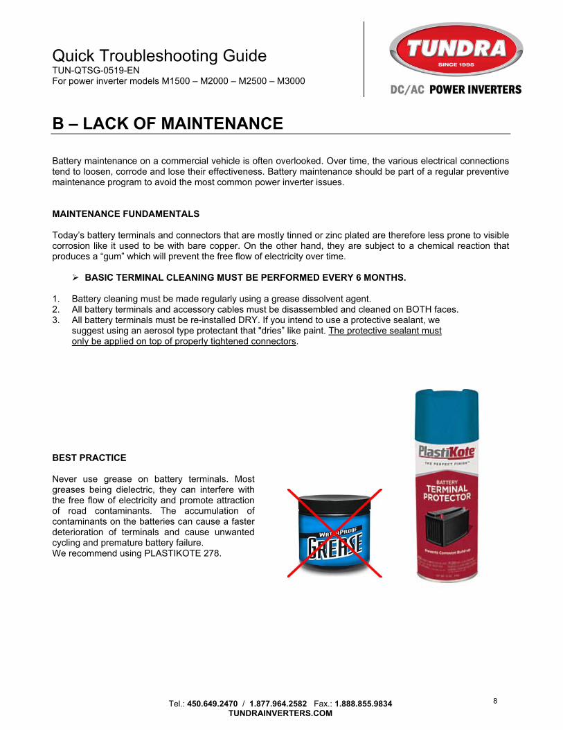
BEST PRACTICE Never use grease on battery terminals. Most greases being dielectric, they can interfere with the free flow of electricity and promote attraction of road contaminants. The accumulation of contaminants on the batteries can cause a faster deterioration of terminals and cause unwanted cycling and premature battery failure. We recommend using PLASTIKOTE 278.
8
Quick Troubleshooting Guide TUN-QTSG-0519-EN For power inverter models M1500 – M2000 – M2500 – M3000
Tel.: 450.649.2470 / 1.877.964.2582 Fax.: 1.888.855.9834
TUNDRAINVERTERS.COM
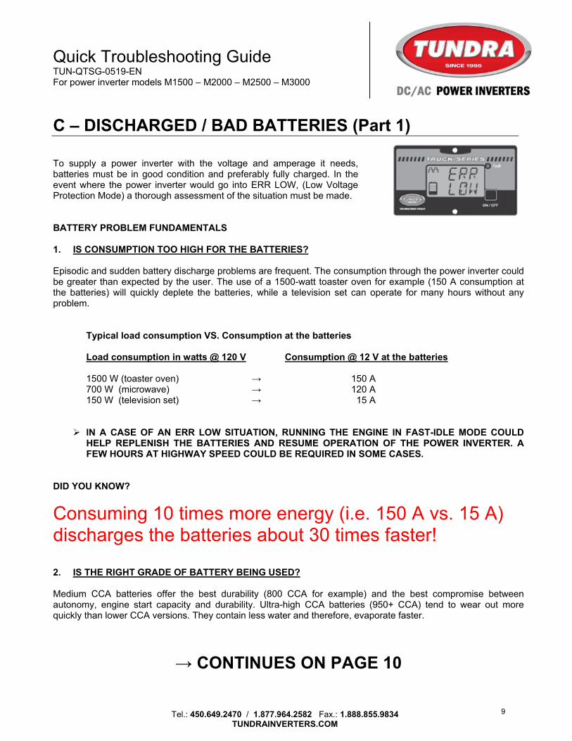
C – DISCHARGED / BAD BATTERIES (Part 1) To supply a power inverter with the voltage and amperage it needs, batteries must be in good condition and preferably fully charged. In the event where the power inverter would go into ERR LOW, (Low Voltage Protection Mode) a thorough assessment of the situation must be made. BATTERY PROBLEM FUNDAMENTALS 1. IS CONSUMPTION TOO HIGH FOR THE BATTERIES? Episodic and sudden battery discharge problems are frequent. The consumption through the power inverter could be greater than expected by the user. The use of a 1500-watt toaster oven for example (150 A consumption at the batteries) will quickly deplete the batteries, while a television set can operate for many hours without any problem.
Typical load consumption VS. Consumption at the batteries
Load consumption in watts @ 120 V Consumption @ 12 V at the batteries
1500 W (toaster oven) → 150 A 700 W (microwave) → 120 A 150 W (television set) → 15 A
IN A CASE OF AN ERR LOW SITUATION, RUNNING THE ENGINE IN FAST-IDLE MODE COULD
HELP REPLENISH THE BATTERIES AND RESUME OPERATION OF THE POWER INVERTER. A FEW HOURS AT HIGHWAY SPEED COULD BE REQUIRED IN SOME CASES.
DID YOU KNOW?
Consuming 10 times more energy (i.e. 150 A vs. 15 A) discharges the batteries about 30 times faster!
2. IS THE RIGHT GRADE OF BATTERY BEING USED? Medium CCA batteries offer the best durability (800 CCA for example) and the best compromise between autonomy, engine start capacity and durability. Ultra-high CCA batteries (950+ CCA) tend to wear out more quickly than lower CCA versions. They contain less water and therefore, evaporate faster.
→ CONTINUES ON PAGE 10
9
Quick Troubleshooting Guide TUN-QTSG-0519-EN For power inverter models M1500 – M2000 – M2500 – M3000
Tel.: 450.649.2470 / 1.877.964.2582 Fax.: 1.888.855.9834
TUNDRAINVERTERS.COM
C – DISCHARGED / BAD BATTERIES (Part 2) 3. ARE THE BATTERIES IN GOOD CONDITION?
A battery bank that gets discharged faster than usual could be at the end of its useful life.
Slowly recharge all 4 batteries and load-test them individually using a quality AVR designed for this purpose. If one or more batteries are to be replaced, you should replace them all at once and keep the good batteries for later temporary fixes.
4. ARE THE BATTERIES CLEAN? Batteries should always be kept clean. The accumulation of dirt and wet contaminants tends to create a constant discharge pattern (cycling) and favors premature wear. See PROCEDURE B (Page 8).
5. ARE THE BATTERIES RUNNING OUT OF POWER AFTER SEVERAL DAYS OF INACTIVITY? Tundra power inverters consume about 150 mA (0.150 A) when turned ON and left unattended (no load is supplied). At this level of consumption, it would take several weeks before completely discharging a truck battery bank. If you have such discharg problems after of a few days of inactivity, it is most likely due to the following two reasons:
A. The battery bank could be at the end of its useful life.
Slowly recharge all 4 batteries and load-test them individually using a quality AVR
designed for this purpose. If one or more batteries are to be replaced, you should replace them all at once
and keep the good batteries for temporary fixes. At the same time, verify alternator capacity.
B. You are dealing with one or more parasitic loads that are unrelated to the power inverter and that
discharge the vehicle's batteries (e.g. CB radio, refrigerator, electric blanket, fan, lamp).
If the batteries of the vehicle have been tested as functional, it is recommended you look for a parasitic load before suspecting the inverter. See PROCEDURE D (Page 11).
BEST PRACTICE
A. Batteries should never be tested without being slowly recharged. B. When evaluating batteries, alternator capacity should always be verified at the same time. C. Never replace only one battery on a bank of 4 batteries. Combining new batteries with older ones will
promote a rapid deterioration of the most recent / better batteries.
10
Quick Troubleshooting Guide TUN-QTSG-0519-EN For power inverter models M1500 – M2000 – M2500 – M3000
Tel.: 450.649.2470 / 1.877.964.2582 Fax.: 1.888.855.9834
TUNDRAINVERTERS.COM
D – VEHICLE ELECTRICAL SYSTEM ISSUES Discharged batteries cause engine starting problems for which the power inverter is always suspected. But electrical issues interfering with the operation of the vehicle can also interfere with the operation of the power inverter. Below is a liste of the most common problems. 1. CHARGING PROBLEMS Commercial trucks frequently experience charging problems. In case of unusual battery discharge, the alternator should be checked. 2. IMPROPER ALTERNATOR CAPACITY A commercial truck equipped with an alternator of 160 A may experience frequent charging capacity problems. If consumption is greater than the alternator’s charging capacity, the batteries may never fully charge, even if the vehicle has been driven for more than eight consecutive hours. This situation occurs mainly in winter and/or at night, when the various electrical systems are highly solicited. If the batteries are in a discharged state and the alternator is testing good, you should consider replacing it with a more powerful one. 3. PARASITIC (GHOST) LOADS A parasitic load consumes energy even when the vehicle's engine is not running. Parasitic loads are common in commercial vehicles. They essentially serve to store the user's parameters and to power the internal clocks of the various on-board electronic systems.
Normal parasitic loads: ECM’s (powertrain, cab, etc.), radio memory, alarm system, tracking system.
If you have deep discharge problems after 2-3 days of inactivity you must:
A. Investigate if the driver may have left something connected (refrigerator, lighting, etc.) B. Make sure the batteries are clean. Contaminants on the batteries can generate a parasitic load, and
cause unwanted cycling and faster discharge of the batteries. C. Check for parasitic loads that might be responsible for draining the batteries. Verify all onboard systems.
See PROCEDURE D (ANNEX 2). 4. ENGINE START PROBLEM Starting problems can be caused by many factors other than the state of the truck's batteries and/or side effects of the power inverter. Here are three of the most common causes:
A. Corrosion at the various starter connections B. Starter at the end of its useful life / internal corrosion or severe wear C. Corrosion on the battery terminals
11
Quick Troubleshooting Guide TUN-QTSG-0519-EN For power inverter models M1500 – M2000 – M2500 – M3000
Tel.: 450.649.2470 / 1.877.964.2582 Fax.: 1.888.855.9834
TUNDRAINVERTERS.COM
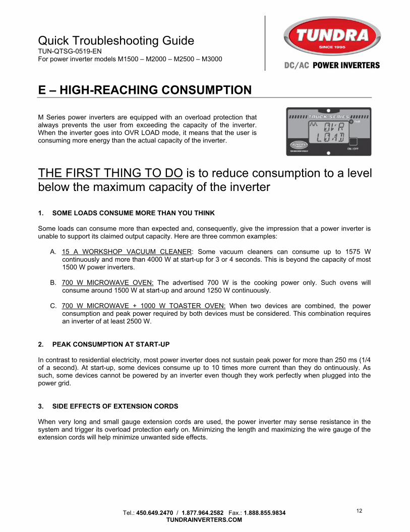
E – HIGH-REACHING CONSUMPTION M Series power inverters are equipped with an overload protection that always prevents the user from exceeding the capacity of the inverter. When the inverter goes into OVR LOAD mode, it means that the user is consuming more energy than the actual capacity of the inverter.
THE FIRST THING TO DO is to reduce consumption to a level below the maximum capacity of the inverter 1. SOME LOADS CONSUME MORE THAN YOU THINK Some loads can consume more than expected and, consequently, give the impression that a power inverter is unable to support its claimed output capacity. Here are three common examples:
A. 15 A WORKSHOP VACUUM CLEANER: Some vacuum cleaners can consume up to 1575 W continuously and more than 4000 W at start-up for 3 or 4 seconds. This is beyond the capacity of most 1500 W power inverters.
B. 700 W MICROWAVE OVEN: The advertised 700 W is the cooking power only. Such ovens will consume around 1500 W at start-up and around 1250 W continuously.
C. 700 W MICROWAVE + 1000 W TOASTER OVEN: When two devices are combined, the power consumption and peak power required by both devices must be considered. This combination requires an inverter of at least 2500 W.
2. PEAK CONSUMPTION AT START-UP In contrast to residential electricity, most power inverter does not sustain peak power for more than 250 ms (1/4 of a second). At start-up, some devices consume up to 10 times more current than they do ontinuously. As such, some devices cannot be powered by an inverter even though they work perfectly when plugged into the power grid. 3. SIDE EFFECTS OF EXTENSION CORDS When very long and small gauge extension cords are used, the power inverter may sense resistance in the system and trigger its overload protection early on. Minimizing the length and maximizing the wire gauge of the extension cords will help minimize unwanted side effects.
12
Quick Troubleshooting Guide TUN-QTSG-0519-EN For power inverter models M1500 – M2000 – M2500 – M3000
Tel.: 450.649.2470 / 1.877.964.2582 Fax.: 1.888.855.9834
TUNDRAINVERTERS.COM
F – INADEQUATE / DAMAGED 120 V WIRING Problems with 120 V wiring can interfere with the proper operation of the power inverter. When an output capacity problem is suspected, THE FIRST THING TO DO is to disconnect all extension cords and power strips from the power inverter and run a test directly from the inverter. 120 V WIRING FUNDAMENTALS 1. SOME ELECTRICAL CORDS ARE INADEQUATE
A. The ideal wire gauge of an extension cord is AWG14. (AWG16 is acceptable on power inverters of 1500 W and under;) All extension cords with smaller gauges (AWG18 - AWG20 - AWG22) are to be avoided.
B. A lengthy extension cord may create resistance in the output of a power inverter and reduce the available power. It is recommended to limit the length of an extension cord to 15 feet.
C. “Dollar store” like products should be avoided.
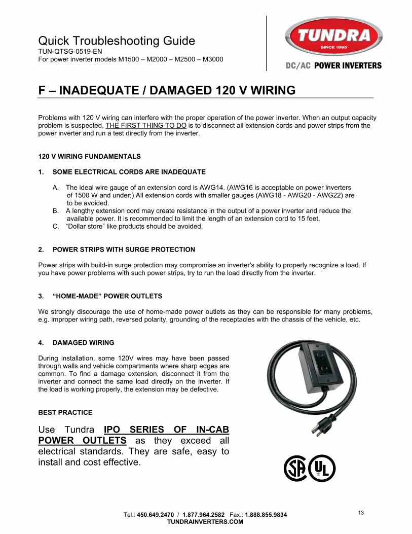
2. POWER STRIPS WITH SURGE PROTECTION Power strips with build-in surge protection may compromise an inverter's ability to properly recognize a load. If you have power problems with such power strips, try to run the load directly from the inverter. 3. “HOME-MADE” POWER OUTLETS We strongly discourage the use of home-made power outlets as they can be responsible for many problems, e.g. improper wiring path, reversed polarity, grounding of the receptacles with the chassis of the vehicle, etc. 4. DAMAGED WIRING During installation, some 120V wires may have been passed through walls and vehicle compartments where sharp edges are common. To find a damage extension, disconnect it from the inverter and connect the same load directly on the inverter. If the load is working properly, the extension may be defective. BEST PRACTICE
Use Tundra IPO SERIES OF IN-CAB POWER OUTLETS as they exceed all electrical standards. They are safe, easy to install and cost effective.
13
Quick Troubleshooting Guide TUN-QTSG-0519-EN For power inverter models M1500 – M2000 – M2500 – M3000
Tel.: 450.649.2470 / 1.877.964.2582 Fax.: 1.888.855.9834
TUNDRAINVERTERS.COM
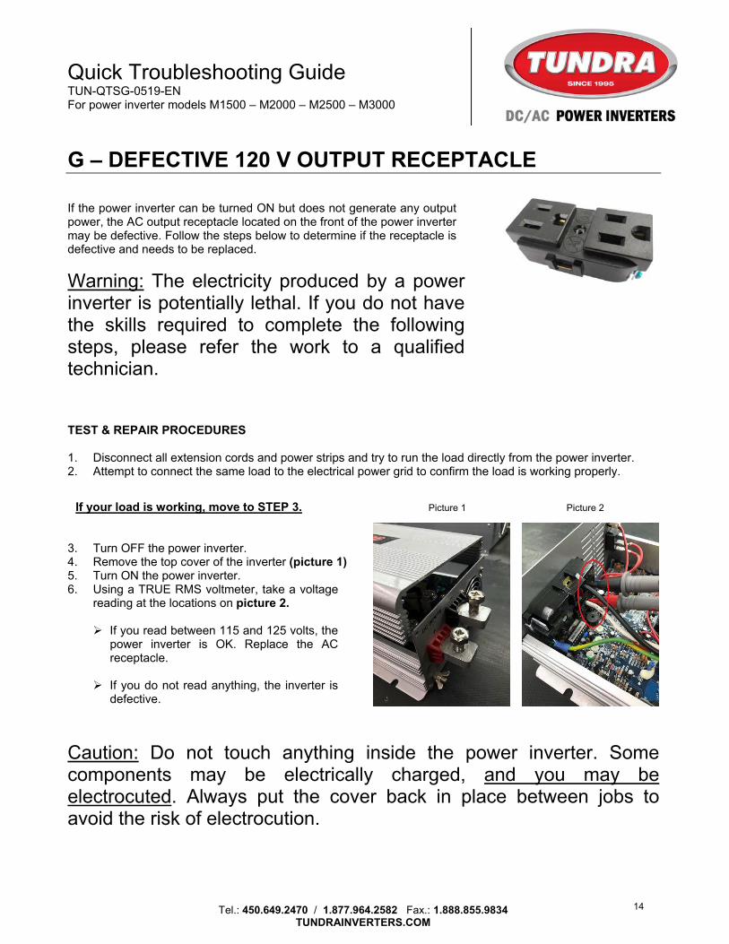
G – DEFECTIVE 120 V OUTPUT RECEPTACLE If the power inverter can be turned ON but does not generate any output power, the AC output receptacle located on the front of the power inverter may be defective. Follow the steps below to determine if the receptacle is defective and needs to be replaced.
Warning: The electricity produced by a power inverter is potentially lethal. If you do not have the skills required to complete the following steps, please refer the work to a qualified technician. TEST & REPAIR PROCEDURES 1. Disconnect all extension cords and power strips and try to run the load directly from the power inverter. 2. Attempt to connect the same load to the electrical power grid to confirm the load is working properly.
If your load is working, move to STEP 3. Picture 1 Picture 2
3. Turn OFF the power inverter. 4. Remove the top cover of the inverter (picture 1) 5. Turn ON the power inverter. 6. Using a TRUE RMS voltmeter, take a voltage
reading at the locations on picture 2.
If you read between 115 and 125 volts, the power inverter is OK. Replace the AC receptacle.
If you do not read anything, the inverter is
defective.
Caution: Do not touch anything inside the power inverter. Some components may be electrically charged, and you may be electrocuted. Always put the cover back in place between jobs to avoid the risk of electrocution.
14
Quick Troubleshooting Guide TUN-QTSG-0519-EN For power inverter models M1500 – M2000 – M2500 – M3000
Tel.: 450.649.2470 / 1.877.964.2582 Fax.: 1.888.855.9834
TUNDRAINVERTERS.COM
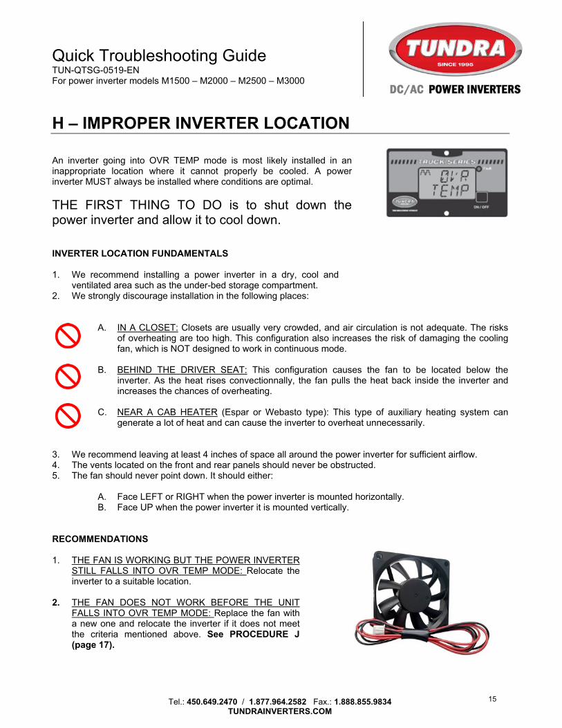
H – IMPROPER INVERTER LOCATION An inverter going into OVR TEMP mode is most likely installed in an inappropriate location where it cannot properly be cooled. A power inverter MUST always be installed where conditions are optimal.
THE FIRST THING TO DO is to shut down the power inverter and allow it to cool down. INVERTER LOCATION FUNDAMENTALS 1. We recommend installing a power inverter in a dry, cool and
ventilated area such as the under-bed storage compartment. 2. We strongly discourage installation in the following places:
A. IN A CLOSET: Closets are usually very crowded, and air circulation is not adequate. The risks of overheating are too high. This configuration also increases the risk of damaging the cooling fan, which is NOT designed to work in continuous mode.
B. BEHIND THE DRIVER SEAT: This configuration causes the fan to be located below the
inverter. As the heat rises convectionnally, the fan pulls the heat back inside the inverter and increases the chances of overheating.
C. NEAR A CAB HEATER (Espar or Webasto type): This type of auxiliary heating system can
generate a lot of heat and can cause the inverter to overheat unnecessarily. 3. We recommend leaving at least 4 inches of space all around the power inverter for sufficient airflow. 4. The vents located on the front and rear panels should never be obstructed. 5. The fan should never point down. It should either:
A. Face LEFT or RIGHT when the power inverter is mounted horizontally. B. Face UP when the power inverter it is mounted vertically.
RECOMMENDATIONS 1. THE FAN IS WORKING BUT THE POWER INVERTER
STILL FALLS INTO OVR TEMP MODE: Relocate the inverter to a suitable location.
2. THE FAN DOES NOT WORK BEFORE THE UNIT
FALLS INTO OVR TEMP MODE: Replace the fan with a new one and relocate the inverter if it does not meet the criteria mentioned above. See PROCEDURE J (page 17).
15
Quick Troubleshooting Guide TUN-QTSG-0519-EN For power inverter models M1500 – M2000 – M2500 – M3000
Tel.: 450.649.2470 / 1.877.964.2582 Fax.: 1.888.855.9834
TUNDRAINVERTERS.COM
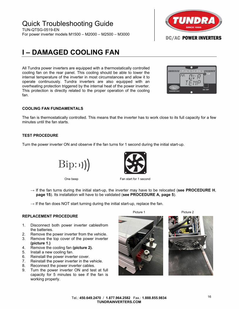
I – DAMAGED COOLING FAN All Tundra power inverters are equipped with a thermostatically controlled cooling fan on the rear panel. This cooling should be able to lower the internal temperature of the inverter in most circumstances and allow it to operate continuously. Tundra inverters are also equipped with an overheating protection triggered by the internal heat of the power inverter. This protection is directly related to the proper operation of the cooling fan. COOLING FAN FUNDAMENTALS The fan is thermostatically controlled. This means that the inverter has to work close to its full capacity for a few minutes until the fan starts. TEST PROCEDURE Turn the power inverter ON and observe if the fan turns for 1 second during the initial start-up.
One beep Fan start for 1 second
→ If the fan turns during the initial start-up, the inverter may have to be relocated (see PROCEDURE H, page 15). Its installation will have to be validated (see PROCEDURE A, page 5).
→ If the fan does NOT start turning during the initial start-up, replace the fan.
Picture 1 Picture 2
REPLACEMENT PROCEDURE 1. Disconnect both power inverter cablesfrom
the batteries. 2. Remove the power inverter from the vehicle. 3. Remove the top cover of the power inverter
(picture 1.) 4. Remove the cooling fan (picture 2). 5. Install a new cooling fan. 6. Reinstall the power inverter cover. 7. Reinstall the power inverter in the vehicle. 8. Reconnect the power inverter cables. 9. Turn the power inverter ON and test at full
capacity for 5 minutes to see if the fan is working properly.
16
Quick Troubleshooting Guide TUN-QTSG-0519-EN For power inverter models M1500 – M2000 – M2500 – M3000
Tel.: 450.649.2470 / 1.877.964.2582 Fax.: 1.888.855.9834
TUNDRAINVERTERS.COM
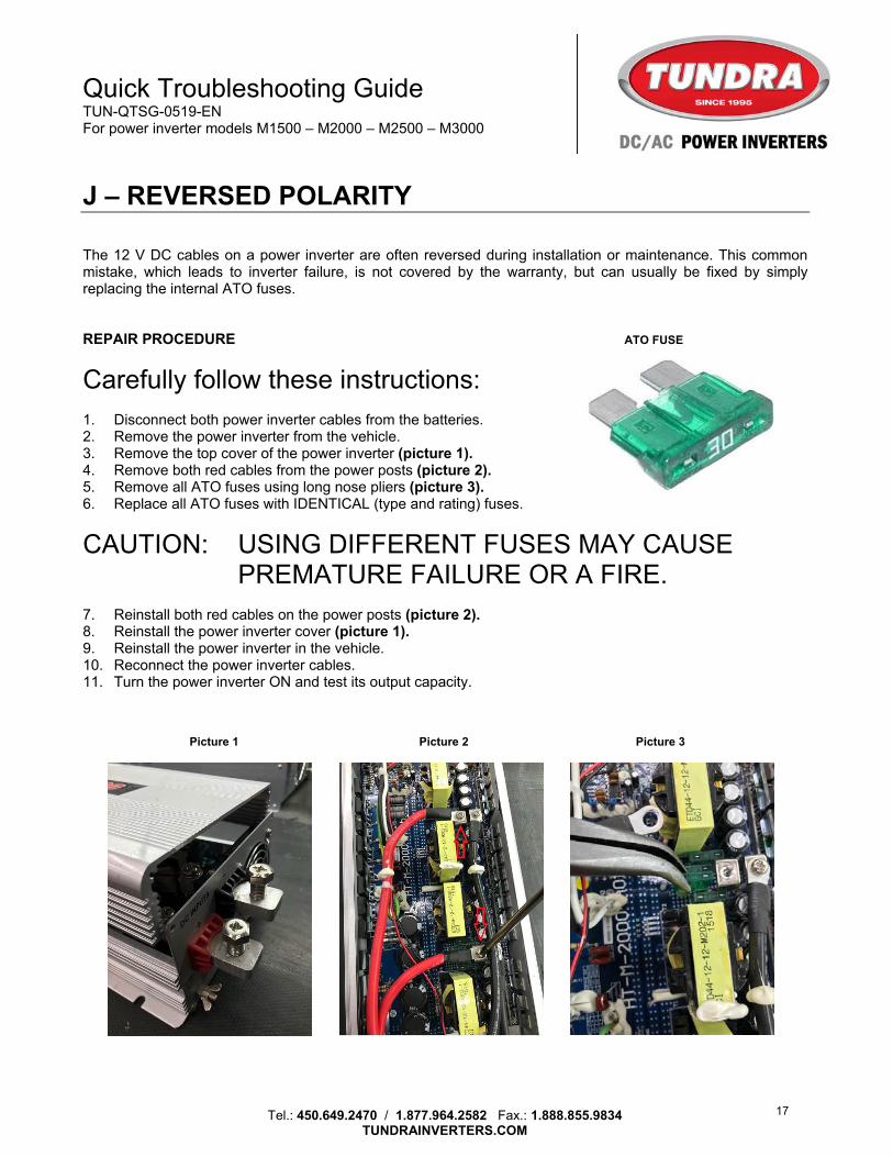
J – REVERSED POLARITY The 12 V DC cables on a power inverter are often reversed during installation or maintenance. This common mistake, which leads to inverter failure, is not covered by the warranty, but can usually be fixed by simply replacing the internal ATO fuses. REPAIR PROCEDURE ATO FUSE
Carefully follow these instructions: 1. Disconnect both power inverter cables from the batteries. 2. Remove the power inverter from the vehicle. 3. Remove the top cover of the power inverter (picture 1). 4. Remove both red cables from the power posts (picture 2). 5. Remove all ATO fuses using long nose pliers (picture 3). 6. Replace all ATO fuses with IDENTICAL (type and rating) fuses.
CAUTION: USING DIFFERENT FUSES MAY CAUSE PREMATURE FAILURE OR A FIRE.
7. Reinstall both red cables on the power posts (picture 2). 8. Reinstall the power inverter cover (picture 1). 9. Reinstall the power inverter in the vehicle. 10. Reconnect the power inverter cables. 11. Turn the power inverter ON and test its output capacity.
Picture 1 Picture 2 Picture 3
17
Quick Troubleshooting Guide TUN-QTSG-0519-EN For power inverter models M1500 – M2000 – M2500 – M3000
Tel.: 450.649.2470 / 1.877.964.2582 Fax.: 1.888.855.9834
TUNDRAINVERTERS.COM
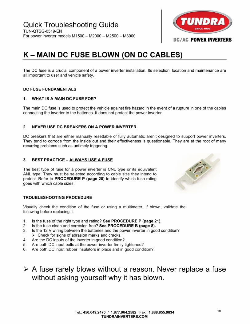
K – MAIN DC FUSE BLOWN (ON DC CABLES) The DC fuse is a crucial component of a power inverter installation. Its selection, location and maintenance are all important to user and vehicle safety. DC FUSE FUNDAMENTALS 1. WHAT IS A MAIN DC FUSE FOR? The main DC fuse is used to protect the vehicle against fire hazard in the event of a rupture in one of the cables connecting the inverter to the batteries. It does not protect the power inverter. 2. NEVER USE DC BREAKERS ON A POWER INVERTER DC breakers that are either manually resettable of fully automatic aren’t designed to support power inverters. They tend to corrode from the inside out and their effectiveness is questionable. They are at the root of many recurring problems such as untimely triggering. 3. BEST PRACTICE – ALWAYS USE A FUSE The best type of fuse for a power inverter is CNL type or its equivalent ANL type. They must be selected according to cable size they intend to protect. Refer to PROCEDURE P (page 20) to identify which fuse rating goes with which cable sizes. TROUBLESHOOTING PROCEDURE Visually check the condition of the fuse or using a multimeter. If blown, validate the following before replacing it. 1. Is the fuse of the right type and rating? See PROCEDURE P (page 21). 2. Is the fuse clean and corrosion free? See PROCEDURE B (page 8). 3. Is the 12 V wiring between the batteries and the power inverter in good condition?
Check for signs of abrasion marks and cracks. 4. Are the DC inputs of the inverter in good condition? 5. Are both DC input bolts at the power inverter firmly tightened? 6. Are both DC input rubber insulators in place and in good condition?
A fuse rarely blows without a reason. Never replace a fuse without asking yourself why it has blown.
18
Quick Troubleshooting Guide TUN-QTSG-0519-EN For power inverter models M1500 – M2000 – M2500 – M3000
Tel.: 450.649.2470 / 1.877.964.2582 Fax.: 1.888.855.9834
TUNDRAINVERTERS.COM
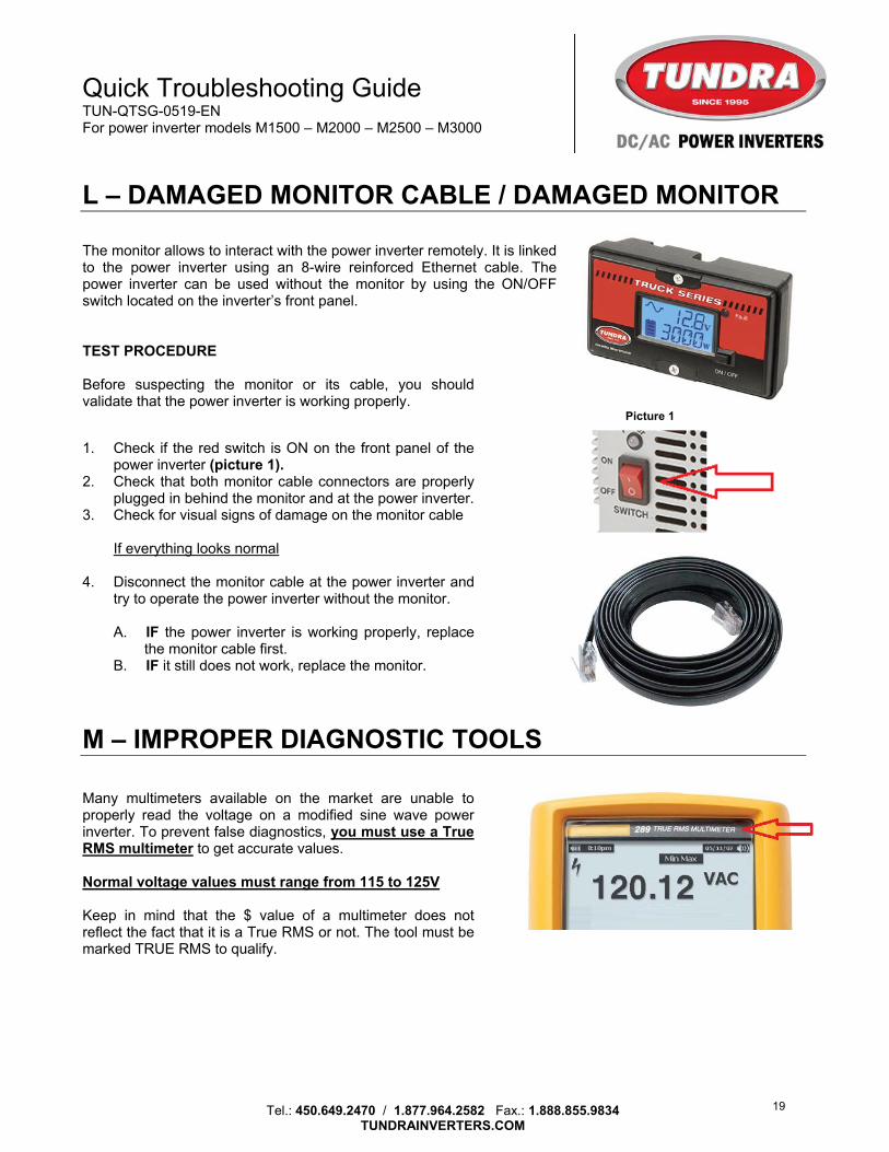
L – DAMAGED MONITOR CABLE / DAMAGED MONITOR The monitor allows to interact with the power inverter remotely. It is linked to the power inverter using an 8-wire reinforced Ethernet cable. The power inverter can be used without the monitor by using the ON/OFF switch located on the inverter’s front panel. TEST PROCEDURE Before suspecting the monitor or its cable, you should validate that the power inverter is working properly. Picture 1
1. Check if the red switch is ON on the front panel of the
power inverter (picture 1). 2. Check that both monitor cable connectors are properly
plugged in behind the monitor and at the power inverter. 3. Check for visual signs of damage on the monitor cable
If everything looks normal 4. Disconnect the monitor cable at the power inverter and
try to operate the power inverter without the monitor. A. IF the power inverter is working properly, replace
the monitor cable first. B. IF it still does not work, replace the monitor.
M – IMPROPER DIAGNOSTIC TOOLS Many multimeters available on the market are unable to properly read the voltage on a modified sine wave power inverter. To prevent false diagnostics, you must use a True RMS multimeter to get accurate values. Normal voltage values must range from 115 to 125V Keep in mind that the $ value of a multimeter does not reflect the fact that it is a True RMS or not. The tool must be marked TRUE RMS to qualify.
19
Quick Troubleshooting Guide TUN-QTSG-0519-EN For power inverter models M1500 – M2000 – M2500 – M3000
Tel.: 450.649.2470 / 1.877.964.2582 Fax.: 1.888.855.9834
TUNDRAINVERTERS.COM
N – MAGNETIC FIELD SIDE EFFECTS Televisions and CB radios are designed to pick up wave signal regardless of their source. Induction loads from electric motors (e.g. refrigerator, compressor) can emit a magnetic field strong enough for it to be interpreted as a signal and therefore, be picked up by a TV or a CB radio. Although the problem may be impossible to eliminate, the following procedure may help you mitigate its effects. IMPROVEMENT PROCEDURE 1. Make sure the DC cables (from the batteries to the power inverter) are attached together as much as
possible between the inverter and the batteries. 2. Ground the CB radio at the batteries directly and NOT through the body of the vehicle. 3. Shut OFF the TV and the CB radio when using an inductive load. (e.g. microwave oven, blender, etc.)
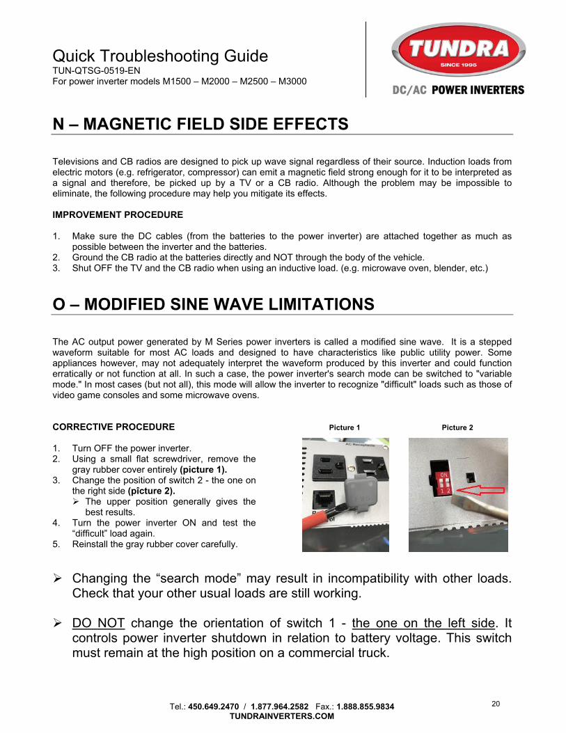
O – MODIFIED SINE WAVE LIMITATIONS The AC output power generated by M Series power inverters is called a modified sine wave. It is a stepped waveform suitable for most AC loads and designed to have characteristics like public utility power. Some appliances however, may not adequately interpret the waveform produced by this inverter and could function erratically or not function at all. In such a case, the power inverter's search mode can be switched to "variable mode." In most cases (but not all), this mode will allow the inverter to recognize "difficult" loads such as those of video game consoles and some microwave ovens. CORRECTIVE PROCEDURE Picture 1 Picture 2 1. Turn OFF the power inverter. 2. Using a small flat screwdriver, remove the
gray rubber cover entirely (picture 1). 3. Change the position of switch 2 - the one on
the right side (pîcture 2). The upper position generally gives the
best results. 4. Turn the power inverter ON and test the
“difficult” load again. 5. Reinstall the gray rubber cover carefully.
Changing the “search mode” may result in incompatibility with other loads. Check that your other usual loads are still working.
DO NOT change the orientation of switch 1 - the one on the left side. It
controls power inverter shutdown in relation to battery voltage. This switch must remain at the high position on a commercial truck.
20
Quick Troubleshooting Guide TUN-QTSG-0519-EN For power inverter models M1500 – M2000 – M2500 – M3000
Tel.: 450.649.2470 / 1.877.964.2582 Fax.: 1.888.855.9834
TUNDRAINVERTERS.COM
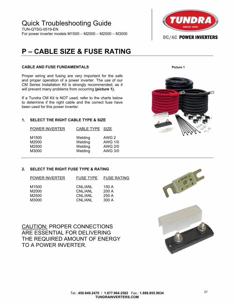
P – CABLE SIZE & FUSE RATING CABLE AND FUSE FUNDAMENTALS Picture 1 Proper wiring and fusing are very important for the safe and proper operation of a power inverter. The use of our CM Series Installation Kit is strongly recommended, as it will prevent many problems from occurring (picture 1). If a Tundra CM Kit is NOT used, refer to the charts below to determine if the right cable and the correct fuse have been used for this power inverter. 1. SELECT THE RIGHT CABLE TYPE & SIZE
POWER INVERTER CABLE TYPE SIZE
M1500 Welding AWG 2 M2000 Welding AWG 1/0 M2500 Welding AWG 2/0 M3000 Welding AWG 3/0
2. SELECT THE RIGHT FUSE TYPE & RATING
POWER INVERTER FUSE TYPE FUSE RATING
M1500 CNL/ANL 150 A M2000 CNL/ANL 200 A M2500 CNL/ANL 250 A M3000 CNL/ANL 300 A
CAUTION: PROPER CONNECTIONS ARE ESSENTIAL FOR DELIVERING THE REQUIRED AMOUNT OF ENERGY TO A POWER INVERTER.
21