timber bridge manual - section 1
TRANSCRIPT

BRIDGE ENGINEERING JUNE 2008

TIMBER BRIDGE MANUAL
EDITION 1 REVISION 0 - JUNE 2008 This manual is provided for the guidance of designers and field staff. Users are advised that in the event of any inconsistency between this manual and other RTA specifications, the latter shall take precedence. If users are in doubt about any issue, please contact Rehabilitation Design Section of Bridge Engineering Branch for clarification.
NOTE: JULY 2018 The Timber Bridge Manual is a reference document only. Some of the contents are out-of-date. It is recommended to seek advice from RMS Bridge and Structural Engineering (Rehabilitation Design) prior to use.
Prepared by Bridge Engineering Engineering Technology Branch Roads and Traffic Authority of NSW Copyright – Roads and Traffic Authority of NSW, 2008
Printed June 2008 APPROVED
Wije Ariyaratne
PRINCIPAL BRIDGE ENGINEER DATE 30/06/2008
(i)
INTRODUCTION TO TIMBER BRIDGE MANUAL This manual is intended to replace all existing RTA/DMR publications concerning timber bridge maintenance, including ‘Manual No. 6 - Bridge Maintenance’ (DMR, 1962 and re-issued 1983) and to complement the ‘Timber Truss Bridge Maintenance Handbook’ (DMR, 1987). It is intended for use by both designers and field personnel. This introduction outlines the basic scope and objectives of the manual. Scope This manual comprises eight sections and encompasses the maintenance and rehabilitation of all timber bridge types including trusses, beam/girder spans, stress laminated bridges, concrete overlays, timber-concrete composites as well as timber substructures. Issues covered include the following: • structure types • inspection • preventative and routine maintenance • rehabilitation and repairs • guidance for engineering design • detailing and durability • specifications • material supply Objectives The primary objective of this manual is to capture the RTA’s corporate knowledge of best practice in timber bridge maintenance. While the manual incorporates, where applicable, all existing documentation and policy, its main purpose has been to document current field practices. The RTA’s bridge maintenance personnel have successfully maintained timber bridges using methods and practices derived from long term experience. Success has depended on this body of knowledge being verbally passed down from the dwindling pool of field “experts” to their successors. This knowledge has now been fully documented in this manual. Another objective of the manual is to produce a document which will stand alone, requiring a minimum of reference to other information. It is intended for use at both the design and field construction level in such a way that the considerations of both levels are properly integrated. This is important because the design/detailing of timber elements plays a major role in the quality and durability of timber bridges.
(ii)
CONTENTS SECTION ONE TIMBER BRIDGES – GENERAL SECTION TWO TIMBER SUBSTRUCTURES SECTION THREE TIMBER TRUSS BRIDGES SECTION FOUR TIMBER GIRDERS, DECKING AND SHEETING SECTION FIVE STRESS LAMINATED TIMBER SYSTEMS SECTION SIX TIMBER CONCRETE OVERLAY BRIDGES SECTION SEVEN TIMBER CONCRETE COMPOSITE BRIDGES SECTION EIGHT PRESERVATIVE AND PROTECTIVE TREATMENTS
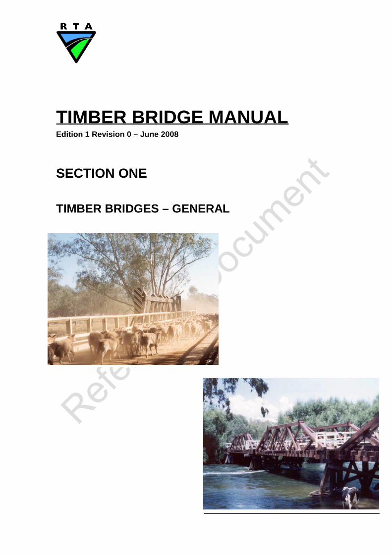
TIMBER BRIDGE MANUAL Edition 1 Revision 0 – June 2008
SECTION ONE TIMBER BRIDGES – GENERAL
TIMBER BRIDGE MANUAL EDITION 1 R 0
(i)
TABLE OF CONTENTS
SECTION ONE
1. TIMBER BRIDGES 1
1. 1 GENERAL 1 1. 1.1 Scope 1 1. 1.2 Objectives 1 1. 1.3 Features 1 1. 1.4 Limits of Application of the Manual 1 1. 1.5 Definitions 2
1. 2 STRUCTURE TYPES AND COMPONENTS 4 1. 2.1 Wood as an Engineering Material 5 1. 2.2 Timber Bridge (Types) Systems 6
1. 2.2.1 Timber Substructures 7 1. 2.2.2 Timber Sheeting 7 1. 2.2.3 Timber Decking 8 1. 2.2.4 Timber Girders 9 1. 2.2.5 Timber Trusses (and Cross Girders) 9 1. 2.2.6 Stress Laminated Timber Systems 10 1. 2.2.7 Concrete Overlays 11 1. 2.2.8 Timber Concrete Composite Systems 11
1. 2.3 Traffic Barriers 12 1. 2.4 Wearing Surfaces 13
1. 3 INSPECTION PROCEDURES 14 1. 3.1 Objectives 14 1. 3.2 General Requirements 15 1. 3.3 Inspection Records 15 1. 3.4 Types and Frequency of Inspections 15 1. 3.5 Visual Inspection 15
1. 3.5.1 Inspection Under Transient Loading 16 1. 3.5.2 Structural Damage and Defects 16 1. 3.5.3 Timber Deterioration 16 1. 3.5.4 Summary of Visual Inspection 17
1. 3.6 Detailed Inspection 17 1. 3.7 Boring of Timber Components 18
1. 3.7.1 General Requirements for Timber Boring 18 1. 3.7.2 Boring Records 18 1. 3.7.3 Boring Terminologies 19 1. 3.7.4 Example Boring Records 19
1. 4 MAINTENANCE 20 1. 4.1 Objectives 20 1. 4.2 General Requirements 20 1. 4.3 Preventative Maintenance 21
(ii)
1. 4.4 Types and Frequency of Maintenance 21 1. 4.5 Annual Maintenance 21 1. 4.6 Three Year Maintenance 22 1. 4.7 Treatment of Fungal and Insect Attack 22
1. 5 REHABILITATION AND REPAIRS 22 1. 5.1 Remedial and Temporary Repairs 23 1. 5.2 Assessment of Remedial and Temporary Repairs 23 1. 5.3 Assessment of Repairs to Primary Structural Components 24 1. 5.4 Rehabilitation and Component Replacement 24
1. 6 ENGINEERING EVALUATION 24 1. 6.1 Design Specifications 24 1. 6.2 Timber Grade for Strength Assessment 25 1. 6.3 Section Properties 26
1. 6.3.1 New Timber Section Sizes 26 1. 6.3.2 Existing Timber Section Sizes 26
1. 6.4 Timber Capacities using AS1720 27 1. 6.4.1 General 27 1. 6.4.2 Design Capacity 27 1. 6.4.3 Characteristic Strengths for Members 27 1. 6.4.4 Characteristic Strengths for Bearing and Joints 28 1. 6.4.5 Capacity Factor φ 28 1. 6.4.6 Duration of Load Factor k1 29 1. 6.4.7 Moisture Condition Factor k4 30 1. 6.4.8 Temperature Factor k6 31 1. 6.4.9 Bearing Factor k7 31 1. 6.4.10 Strength Sharing Factor k9 31 1. 6.4.11 Size Factor k11 32 1. 6.4.12 Stability Factor k12 32
1. 6.5 Structural Analysis for Load Distribution 32
1. 7 DETAILING AND DURABILITY 33 1. 7.1 Timber Selection 33 1. 7.2 Construction Detailing 33
1. 7.2.1 Notches and Section Changes 33 1. 7.2.2 End Split Protection and End Tapers 35 1. 7.2.3 Component Orientation 35 1. 7.2.4 Bolting and Alternate Attachments 36 1. 7.2.5 Other Moisture Trap Conditions 37
1. 7.3 Preservative Protection 37 1. 7.4 Flashing Protection 38
1. 8 SPECIFICATIONS 40 1. 8.1 RTA Specifications 40 1. 8.2 Australian Standards Specifications 40 1. 8.3 Austroads 41

(iii)
1. 9 MATERIAL SUPPLY 41 1. 9.1 Materials 41
1. 9.1.1 Timber Supply - General 42 1. 9.1.2 Timber Supply - Member Replacements 42 1. 9.1.3 Steel Hardware 43
(iv)
LIST OF FIGURES Figure 1.2.1-1 Anisotropic Nature of Wood ........................................... 6 Figure 1.2.2.1-1 Dungog Shire - Timber Pile Abutment .............................. 7 Figure 1.2.2.2-1 Clarencetown Bridge - Longitudinal Timber Sheeting ......... 8 Figure 1.2.2.3-1 Anderson Creek - Timber Decking................................... 8 Figure 1.2.2.4-1 Lignum Creek - Timber Girders ....................................... 9 Figure 1.2.2.5-1 Galston Gorge - Timber Truss ........................................ 9 Figure 1.2.2.5-2 Wakool River - Timber Cross Girder ............................... 10 Figure 1.2.2.6-1 Bridge over Rail at Molong - SLT Hardwood Deck ............ 10 Figure 1.2.2.7-1 Corowa - Timber Girders with Concrete Overlay ............... 11 Figure 1.2.2.8-1 Timber Concrete Modules During Load Testing ................ 11 Figure 1.2.3-1 Leycester Creek - Typical Timber Post, Rail and Kerb ...... 12 Figure 1.2.3-2 Western Region - Light Steel Posts and Traffic Rail .......... 13 Figure 1.2.4-1 Grafton Region - Flush Seal on Timber Sheeting ............. 14 Figure 1.7.2.1-1 Splitting of Girder at Section Change .............................. 34 Figure 1.7.2.1-2 Unnecessary Deep Notch for Pile Bracing ....................... 34 Figure 1.7.2.1-3 Required 1 in 5 Taper ................................................... 35 Figure 1.7.2.2-1 End Split Protection and End Tapers .............................. 35 Figure 1.7.2.3-1 Component Orientation ................................................ 36 Figure 1.7.2.4-1 Rebated Washer Plate Sealed with Epoxy ....................... 36 Figure 1.7.2.4-2 Steel Channel Attachments for Capwale and Girders ........ 37 Figure 1.7.4-1 Flashing on Truss Members .......................................... 38 Figure 1.7.4-2 Flashing on Pile Top .................................................... 38 Figure 1.7.4-3 Flashing on Ends of Horizontal Members (Inappropriate Use)...................................................... 39
Section 1 1 of 43
1. TIMBER BRIDGES
1. 1 GENERAL While this manual represents a combination of the existing documentation and research activities, the primary emphasis during its development has been on documentation of current best practice for timber bridges in NSW.
1. 1.1 Scope Section 1 covers the common issues in the design, construction and maintenance of all timber bridge types and components.
1. 1.2 Objectives The objectives of this section, and those of the complete manual, are to outline the requirements of, and to provide guidance in relation to, the design, construction and maintenance of all timber bridges and their components with specific emphasis on: • inspection procedures • preventative and routine maintenance • rehabilitation and repairs • engineering design and evaluation • detailing and durability • specifications • material supply
1. 1.3 Features This section outlines the general requirements and procedures for all timber bridges and their components. It is to be read in conjunction with the other sections which deal specifically with the bridge type or subject under consideration. These subsequent sections provide specific additional requirements relating to the individual bridge types and/or components, as well as protective treatments.
1. 1.4 Limits of Application of the Manual This manual deals specifically with the timber bridge systems and components outlined in Subsection 1. 2.2. However, its applicability does vary within this frame of reference. The following outlines some of the basic limitations:

TIMBER BRIDGE MANUAL EDITION 1 R 0
Section 1 2 of 43
• The manual provides some guidance and examples on the types of traffic barrier posts, attachments and rail systems that can be used on timber bridges. It does not provide the design procedures or details for these elements.
• The manual covers the timber decking on existing steel structures with
timber decks but does not cover the steel elements. • The manual does not cover steel piles and concrete substructures
supporting timber bridges • The manual refers to typical wearing surfaces for timber decking but, except
as provided in specific sections, does not provide details on materials or application.
1. 1.5 Definitions This subsection contains a list of definitions pertaining to common terminologies, phrases and components related to timber bridges. Following sections will provide additional definitions related specifically to the bridge type and/or subject covered by that section. Abutments
Substructure components at the ends of a bridge providing support to the superstructure and retaining the approach fill
Bearing The contact surface or element supporting a component
Bracing Component providing stability to a member, or group of members, such as the timber cross bracing on piles
Capwales Pair of horizontal timber components (typically 300 mm x 150 mm) at the tops of piles, or posts, providing bearing for the superstructure.
Components General term referring to members forming part of a structural assembly
Composite
A member or system with two components, or materials structurally joined together to form one member.
Corbel
A longitudinal timber bearing member which provides support and some continuity between bending members in adjacent spans
Section 1 3 of 43
Decking Closely spaced sawn timbers up to 125 mm deep (200 mm to 250 mm wide) supported on girders as defined in Subsection 1. 2.2.3.
Deterioration A general term referring to either decay or insect attack in timber, corrosion in steel and general wear of components
Engineered / Engineering
Referring to design and/or evaluation by an engineer certified by the Institution of Engineers Australia
Flexural Member
A component primarily subjected to bending between these supports Girders
Traditionally round timber members from 300 mm to 500 mm in diameter oriented longitudinally. Further defined in Subsection 1. 2.2.4.
Headstock Single horizontal timber component (typically 300 mm x 300 mm) at the tops of piles, or posts, providing bearing for the superstructure.
Interpretation (in RTA Specifications): In order to avoid repetition, any expression using "permitted", "specified", "approval", "approved ", "directed", and /or "inspection", shall be interpreted as if followed by the words "by" (or "of") the Principal’s Representative. In order to avoid repetition, any expression using the term "Engineering Certification" shall be interpreted as being a certificate provided by an engineer who is eligible for membership of the Institution of Engineers Australia.
Longitudinal A component oriented parallel to the roadway
Piers
Intermediate substructure components providing support to the superstructure
Piles
Round timber poles driven into the ground to provide support for a structure
Principal’s Representative
The nominated representative of the Principal

Section 1 4 of 43
Protective Treatment General term referring to the protection applied to components to provide resistance to deterioration
Seasoned
A timber component which has been air dried to remove some moisture Sheeting
Timber plank running surface, generally 50 mm to 75 mm thick, running parallel to the roadway and supported on the timber decking
Stress Laminated Timber A structural system formed from small timber elements stressed together using prestressing tendons (see Section 5)
Structural Defects
A general term referring to damage in timber such as splits, checks, fractures, pipes and crushing.
Substructure
The timber components supporting the superstructure as defined in Subsection 1. 2.2.1
Superstructure All components above the substructure
Timber Cross Girders (Beams)
Typically large section and high quality timbers of up to 400 mm x 400 mm cross section oriented transversely as part of a larger structure and supporting traditional timber deck systems.
Timber Trusses
Typically, large section and high quality timber components assembled to form trusses which can span distances of over 15 m.
Transverse
A component oriented perpendicular to the roadway Wearing Surface
The top coating on a bridge deck provided to resist wear due to traffic
1. 2 STRUCTURE TYPES AND COMPONENTS The following outlines the basic material requirements, structure types and components covered by this manual. Additional material and component specifications are provided in the subsequent sections dealing with the specific structure types.
Section 1 5 of 43
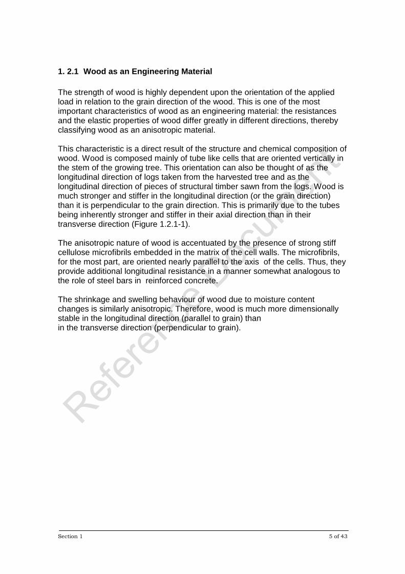
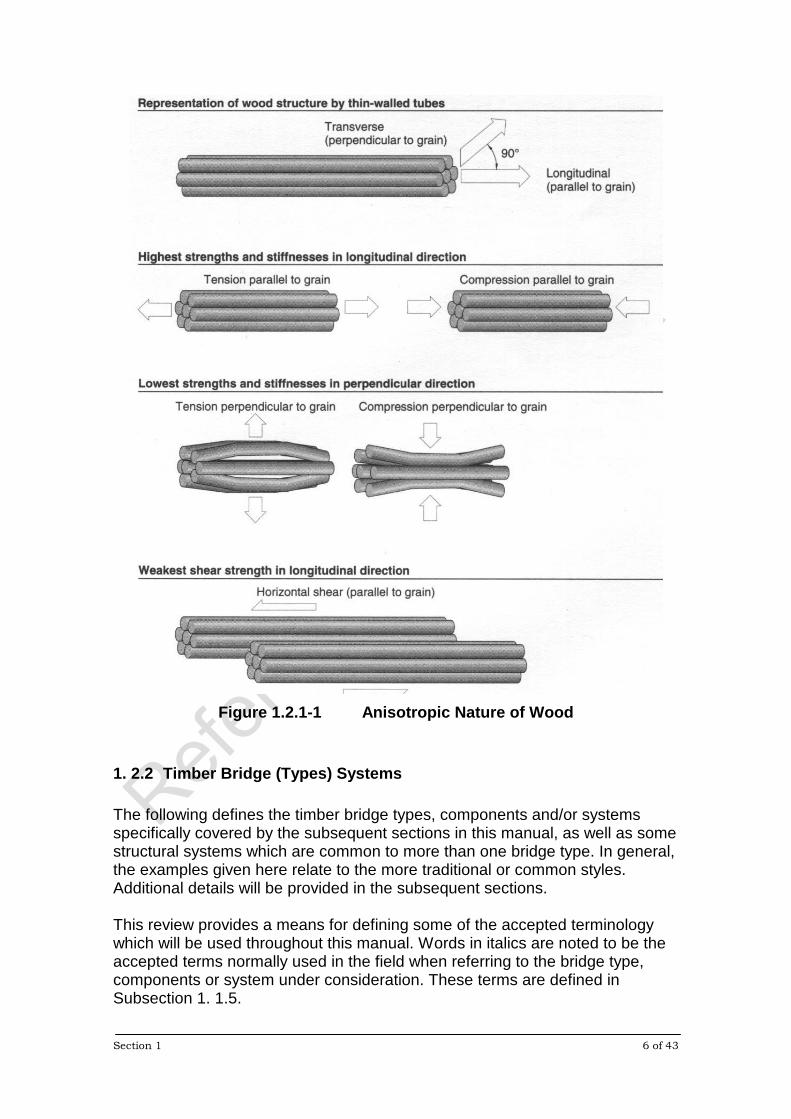
1. 2.1 Wood as an Engineering Material The strength of wood is highly dependent upon the orientation of the applied load in relation to the grain direction of the wood. This is one of the most important characteristics of wood as an engineering material: the resistances and the elastic properties of wood differ greatly in different directions, thereby classifying wood as an anisotropic material. This characteristic is a direct result of the structure and chemical composition of wood. Wood is composed mainly of tube like cells that are oriented vertically in the stem of the growing tree. This orientation can also be thought of as the longitudinal direction of logs taken from the harvested tree and as the longitudinal direction of pieces of structural timber sawn from the logs. Wood is much stronger and stiffer in the longitudinal direction (or the grain direction) than it is perpendicular to the grain direction. This is primarily due to the tubes being inherently stronger and stiffer in their axial direction than in their transverse direction (Figure 1.2.1-1). The anisotropic nature of wood is accentuated by the presence of strong stiff cellulose microfibrils embedded in the matrix of the cell walls. The microfibrils, for the most part, are oriented nearly parallel to the axis of the cells. Thus, they provide additional longitudinal resistance in a manner somewhat analogous to the role of steel bars in reinforced concrete. The shrinkage and swelling behaviour of wood due to moisture content changes is similarly anisotropic. Therefore, wood is much more dimensionally stable in the longitudinal direction (parallel to grain) than in the transverse direction (perpendicular to grain).
Section 1 6 of 43
Figure 1.2.1-1 Anisotropic Nature of Wood
1. 2.2 Timber Bridge (Types) Systems The following defines the timber bridge types, components and/or systems specifically covered by the subsequent sections in this manual, as well as some structural systems which are common to more than one bridge type. In general, the examples given here relate to the more traditional or common styles. Additional details will be provided in the subsequent sections. This review provides a means for defining some of the accepted terminology which will be used throughout this manual. Words in italics are noted to be the accepted terms normally used in the field when referring to the bridge type, components or system under consideration. These terms are defined in Subsection 1. 1.5.
Section 1 7 of 43
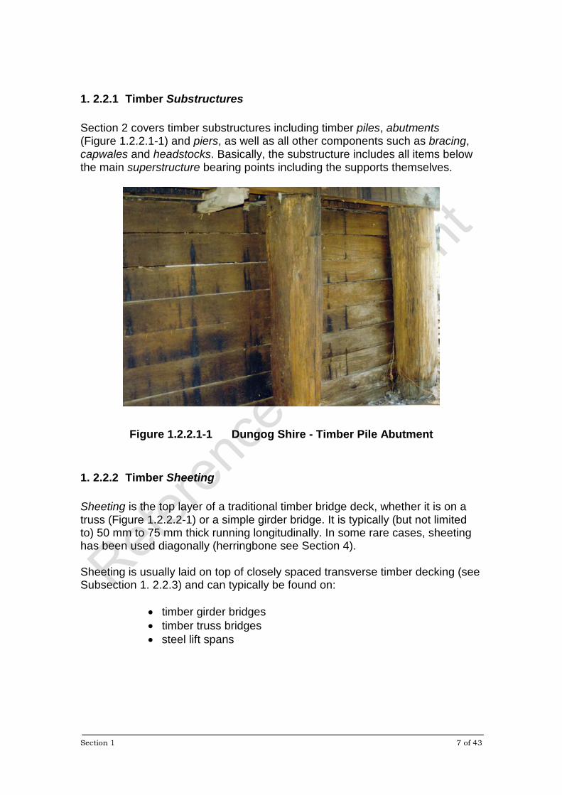
1. 2.2.1 Timber Substructures Section 2 covers timber substructures including timber piles, abutments (Figure 1.2.2.1-1) and piers, as well as all other components such as bracing, capwales and headstocks. Basically, the substructure includes all items below the main superstructure bearing points including the supports themselves.
Figure 1.2.2.1-1 Dungog Shire - Timber Pile Abutment
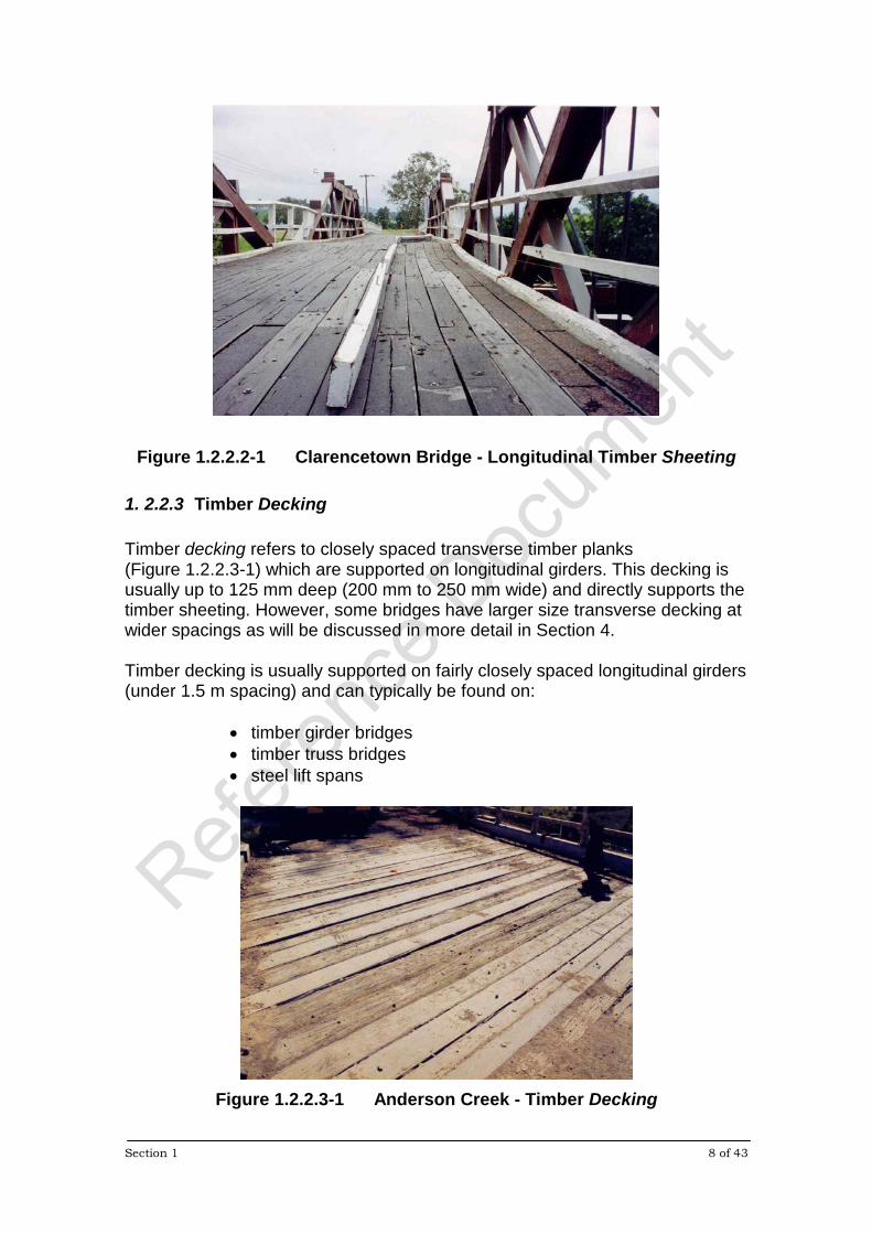
1. 2.2.2 Timber Sheeting Sheeting is the top layer of a traditional timber bridge deck, whether it is on a truss (Figure 1.2.2.2-1) or a simple girder bridge. It is typically (but not limited to) 50 mm to 75 mm thick running longitudinally. In some rare cases, sheeting has been used diagonally (herringbone see Section 4). Sheeting is usually laid on top of closely spaced transverse timber decking (see Subsection 1. 2.2.3) and can typically be found on:
• timber girder bridges • timber truss bridges • steel lift spans
Section 1 8 of 43
Figure 1.2.2.2-1 Clarencetown Bridge - Longitudinal Timber Sheeting
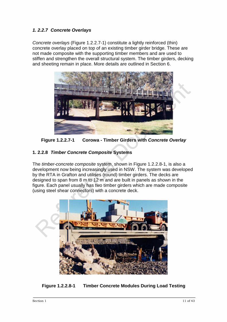
1. 2.2.3 Timber Decking Timber decking refers to closely spaced transverse timber planks (Figure 1.2.2.3-1) which are supported on longitudinal girders. This decking is usually up to 125 mm deep (200 mm to 250 mm wide) and directly supports the timber sheeting. However, some bridges have larger size transverse decking at wider spacings as will be discussed in more detail in Section 4. Timber decking is usually supported on fairly closely spaced longitudinal girders (under 1.5 m spacing) and can typically be found on:
• timber girder bridges • timber truss bridges • steel lift spans
Figure 1.2.2.3-1 Anderson Creek - Timber Decking

Section 1 9 of 43
1. 2.2.4 Timber Girders Timber girders are round, as shown in Figure 1.2.2.4-1, with timber corbels at pier supports. Combined with timber decking and sheeting, timber girders form the most common timber bridge type. The latter combination is also frequently used as a deck system on larger structures such as timber trusses (and even steel lift spans) and sometimes utilises square girders as will be outlined in Section 4.
Figure 1.2.2.4-1 Lignum Creek - Timber Girders
1. 2.2.5 Timber Trusses (and Cross Girders) Section 3 covers timber trusses (Figure 1.2.2.5-1) along with the main timber cross girders shown in Figure 1.2.2.5-2. These members are generally seen as a separate class from the deck systems as they typically use larger section sizes and more durable materials.
Figure 1.2.2.5-1 Galston Gorge - Timber Truss

Section 1 10 of 43
Figure 1.2.2.5-2 Wakool River - Timber Cross Girder
1. 2.2.6 Stress Laminated Timber Systems The stress laminated timber (SLT) system, shown in Figure 1.2.2.6-1, is a development which utilises thin (35 mm to 50 mm thick) timber laminates of widths from 140 mm up to 290 mm (and wider where manufactured timber materials are used). These laminates are oriented on edge (upright) and stressed together using high strength bars or prestressing strands to form a solid structural slab. There are an increasing number of bridges in NSW which utilise the SLT system. Most of these bridges have simple slab decks. However, there are a few which have a more detailed (built-up or cellular) system. The latter are outlined in more detail in Section 5.
Figure 1.2.2.6-1 Bridge over Rail at Molong - SLT Hardwood Deck
Section 1 11 of 43
1. 2.2.7 Concrete Overlays Concrete overlays (Figure 1.2.2.7-1) constitute a lightly reinforced (thin) concrete overlay placed on top of an existing timber girder bridge. These are not made composite with the supporting timber members and are used to stiffen and strengthen the overall structural system. The timber girders, decking and sheeting remain in place. More details are outlined in Section 6.
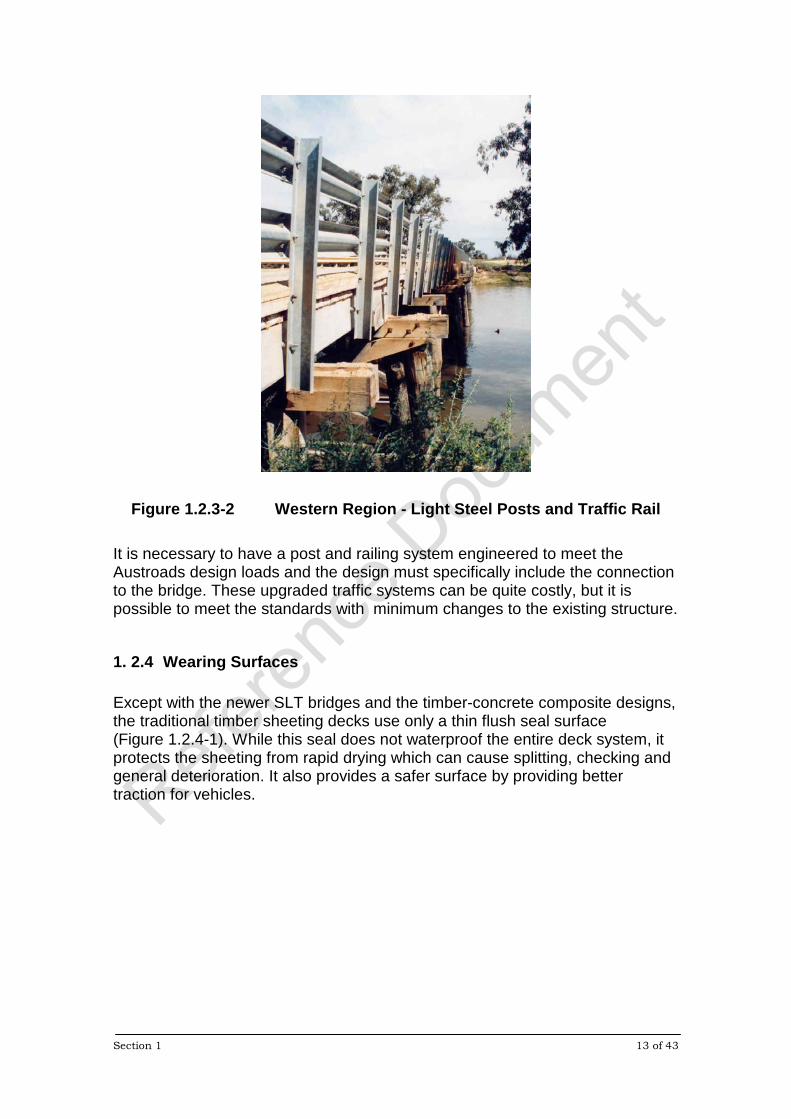
Figure 1.2.2.7-1 Corowa - Timber Girders with Concrete Overlay
1. 2.2.8 Timber Concrete Composite Systems The timber-concrete composite system, shown in Figure 1.2.2.8-1, is also a development now being increasingly used in NSW. The system was developed by the RTA in Grafton and utilises (round) timber girders. The decks are designed to span from 8 m to 12 m and are built in panels as shown in the figure. Each panel usually has two timber girders which are made composite (using steel shear connectors) with a concrete deck.
Figure 1.2.2.8-1 Timber Concrete Modules During Load Testing

Section 1 12 of 43
1. 2.3 Traffic Barriers
Figure 1.2.3-1 Leycester Creek - Typical Timber Post, Rail and Kerb In general, the traditional traffic barriers, railing and kerbs used on timber bridges were not designed to meet any of the types of design loads in use today. The common form of timber post and railing, shown in Figure 1.2.3-1, was developed over the decades from tradition rather than design. The details vary very little from bridge to bridge and have been applied to timber girder bridges as well trusses. Currently, it is considered acceptable to repair an existing timber railing system of this type using the same timber components. However, where a bridge undergoes a major rehabilitation the traffic barriers must be upgraded to meet current design standards. This necessity is derived from the increased liability that the bridge owner faces from possible damages if the public is not properly protected. It should be noted that upgrading is not just simply a matter of facing the existing post system with a new steel traffic rail or adding light steel posts such as shown in Figure 1.2.3-2.
Section 1 13 of 43
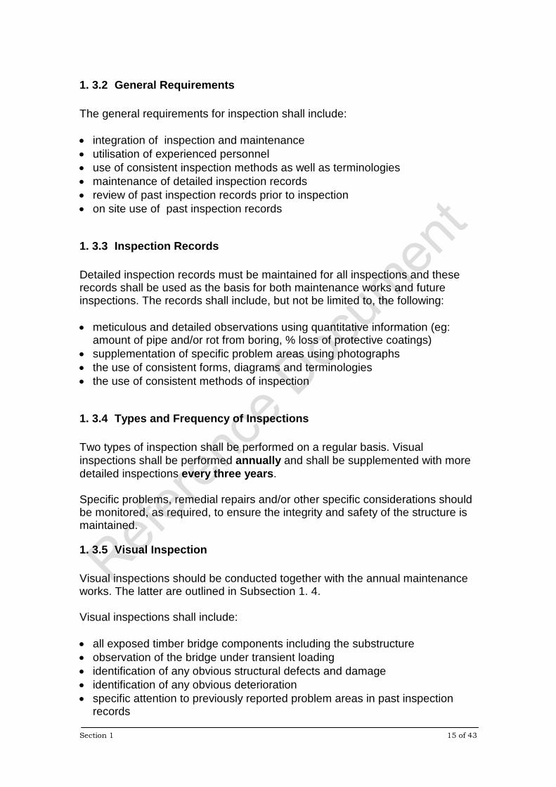
Figure 1.2.3-2 Western Region - Light Steel Posts and Traffic Rail It is necessary to have a post and railing system engineered to meet the Austroads design loads and the design must specifically include the connection to the bridge. These upgraded traffic systems can be quite costly, but it is possible to meet the standards with minimum changes to the existing structure.
1. 2.4 Wearing Surfaces Except with the newer SLT bridges and the timber-concrete composite designs, the traditional timber sheeting decks use only a thin flush seal surface (Figure 1.2.4-1). While this seal does not waterproof the entire deck system, it protects the sheeting from rapid drying which can cause splitting, checking and general deterioration. It also provides a safer surface by providing better traction for vehicles.

Section 1 14 of 43
Figure 1.2.4-1 Grafton Region - Flush Seal on Timber Sheeting Generally, the new timber-concrete composite decks and concrete overlays do not have a wearing surface applied and vehicles travel directly on the concrete. Additional information on these bridge types is provided in Sections 6 and 7. The new SLT bridges require both a waterproofing system as well as a wearing surface. Since the SLT system provides a strong and stiff structural slab, these decks can support any bitumen based wearing surface without cracking. Additional information is provided in Section 5.
1. 3 INSPECTION PROCEDURES The following outlines the basic procedures applying to the inspection of all timber bridge types and components. The subsequent sections provide additional information for the specific bridge types and/or components covered by that section.
1. 3.1 Objectives The general objectives of inspection shall include: • to determine the effectiveness of past maintenance activities • note the changes in the state of previously reported problem areas • to identify problem areas which require maintenance and/or repair • to identify potential problems that could advance and lead to the need for
maintenance in the future
Section 1 15 of 43
1. 3.2 General Requirements The general requirements for inspection shall include: • integration of inspection and maintenance • utilisation of experienced personnel • use of consistent inspection methods as well as terminologies • maintenance of detailed inspection records • review of past inspection records prior to inspection • on site use of past inspection records
1. 3.3 Inspection Records Detailed inspection records must be maintained for all inspections and these records shall be used as the basis for both maintenance works and future inspections. The records shall include, but not be limited to, the following: • meticulous and detailed observations using quantitative information (eg:
amount of pipe and/or rot from boring, % loss of protective coatings) • supplementation of specific problem areas using photographs • the use of consistent forms, diagrams and terminologies • the use of consistent methods of inspection
1. 3.4 Types and Frequency of Inspections Two types of inspection shall be performed on a regular basis. Visual inspections shall be performed annually and shall be supplemented with more detailed inspections every three years. Specific problems, remedial repairs and/or other specific considerations should be monitored, as required, to ensure the integrity and safety of the structure is maintained.
1. 3.5 Visual Inspection Visual inspections should be conducted together with the annual maintenance works. The latter are outlined in Subsection 1. 4. Visual inspections shall include: • all exposed timber bridge components including the substructure • observation of the bridge under transient loading • identification of any obvious structural defects and damage • identification of any obvious deterioration • specific attention to previously reported problem areas in past inspection
records
Section 1 16 of 43
1. 3.5.1 Inspection Under Transient Loading Visual inspection of the bridge under transient loading shall include: • the use of experienced personnel • the use of a reasonably heavy vehicle so that movements are well defined • the use of a specific vehicle, where possible, to provide more consistency in
the bridge movement for comparative purposes The observations and records should include: • all components and connections including the substructure and the
superstructure • overall deformations as well as local movements under the wheel loads • vertical deflections in girders, cross girders and other flexural members, as
well as trusses • any movements of piles and other substructure components • descriptive written record of any apparent problem areas Specific attention should be given to: • apparent excessive movements, as compared to the majority of other
components • inconsistent or uneven performance • movements at joints and connections • known problem areas Specific considerations for the different bridge types and components are outlined in subsequent sections.
1. 3.5.2 Structural Damage and Defects All components and connections shall be inspected for obvious structural defects and damage caused by loading or collisions. These should include: • fractures due to loading, particularly in flexural (bending) members • local crushing at bearings, including the ends of truss members • propagation (or extension) of the natural end splits in flexural members • loose connections, including local crushing of timber and/or enlarged holes
around bolts • collision damage Some critical areas to be inspected for different components and structure types are highlighted in subsequent sections.
1. 3.5.3 Timber Deterioration

Section 1 17 of 43
There are four types of timber deterioration; decay (or fungal attack), insect attack, weathering and fire damage which are all discussed in detail in Section 8. In summary, only decay and insect attack represent a significant danger to timber bridges. Section 8 should be read prior to performing site inspections. All timber components shall be inspected for deterioration caused by decay and/or insect attack. These should include: • sapwood in all components • ground contact areas, such as piles, and abutment components • areas where water is trapped or does not dry out readily • interfaces between components • holes at connections • ends of members, particularly girders, piles and truss members • under flashing • behind other protective coatings, particularly paint Some critical areas to be inspected for different components and structure types are highlighted in the subsequent sections.
1. 3.5.4 Summary of Visual Inspection The following is a summary of the basic requirements for the annual visual inspection of timber bridges: • inspection should be integrated with routine maintenance • previous inspection records should be used on site • the bridge should be observed under transient loads • all exposed areas of all components should be inspected for structural
damage, defects and deterioration • connections and their components should be inspected for signs of
looseness or damage • attention should be given to previously reported problem areas • detail records and photographs should be produced
1. 3.6 Detailed Inspection In addition to the annual visual inspections, a more detailed inspection must be carried out every three years. This inspection should include: • integration of the inspection with the three year maintenance activities
outlined in Subsection 1. 4 • extending visual inspection to hidden areas • exposing questionable areas, particularly between components and buried
portions of the substructure • boring of main structural components as outlined in Subsection 1. 3.7
Section 1 18 of 43
Some critical areas to be inspected for different components and structure types are highlighted in subsequent sections.
1. 3.7 Boring of Timber Components Except as may be noted in the subsequent sections, all main structural components shall be test bored as part of the detailed inspection to determine whether there is internal deterioration. The basic requirements for timber test boring follow. Subsequent sections provide additional requirements related to specific structure types and components. It should be noted that new timber components need not be bored during the first three or four years unless deterioration is suspected.
1. 3.7.1 General Requirements for Timber Boring Test boring of timber components shall satisfy the following general requirements: • use of minimum 12 mm to maximum 16 mm diameter bits depending on the
size of the plugs being used • for horizontal or inclined members the initial holes shall be drilled in the
bottom face of the members first when possible • intersecting horizontal holes at the same location shall only be drilled where
deterioration is found during the initial boring • where horizontal holes are necessary they should be inclined slightly
upwards • components should be drilled at each end of the member first • care shall be taken not to drill completely through a component • all holes (except as noted below) should be treated with a diffusing
preservative and plugged • if free moisture is found during boring it is recommended that the holes in the
bottom faces not be sealed to allow the moisture to drain • measurements of sound and deteriorated material should made to the
nearest 10 mm • the method of drilling and measurement used shall be consistent throughout
the inspection • components shall be marked at the bore locations with waterproof markers • a detailed record of the test bores shall be maintained as outlined in
Subsection 1. 3.7.2
1. 3.7.2 Boring Records Test bore records shall include but not be limited to the following: • the use of quantitative information as much as possible • bore locations and direction of each hole
Section 1 19 of 43
• measurements of the sound and deteriorated material • the use of consistent forms and diagrams • the use of standard terminologies as outlined in Subsection 1. 3.7.3 • a description of the tools used • date, name of inspector and any other descriptive information which may
facilitate future interpretation of the inspection record
1. 3.7.3 Boring Terminologies The following descriptive terminologies shall be used to record the direction of the boreholes and timber condition.
Direction of Bore Holes H = horizontal bore V = vertical bore U = upstream or upwards direction D = downstream or downwards direction A = towards Abutment A B = towards Abutment B
Timber Condition S = solid or sound timber P = pipe (void) R = rot (soft material)
P is used to define an open or voided area which has no residual material in place. R is used to define an area of weak, deteriorated or soft material.
1. 3.7.4 Example Boring Records The following represent several examples of boring records.
Position Direction Timber Condition Member Type 1 VU 150S, 100P, 200S Girder 1 HU 120S, 120P, 210S 2 VU S Girder 3 VU 180S, 30P, 220S Headstock 3 HU 150S, 50P, 250S 40 HA 100S, 150P/R, 100S Pile 40 HD 110S, 120P/R, 120S 42 HB 150S, 50R, 150S Pile 42 HU 150S, 20R, 180S
Section 1 20 of 43
Each bore has a position number which is used to identify the bore on the forms and diagrams. It is also marked on the member adjacent to the bore location. The first bore at position 1 is vertical in the upwards direction and found 150 mm of solid material followed by a 100 mm pipe and then 200 mm of solid material. The second intersecting bore at position 1 was in the horizontal upstream direction and found 120 mm solid, 120 mm pipe and 210 mm of solid. The initial bore at position 2 found no deterioration and so no additional drilling was performed. The initial bore at position 3 was in the vertical upwards direction and found 180 mm solid, 30 mm pipe and 220 mm solid. The intersecting bore was in the horizontal upstream direction and found 150 mm solid, 50 mm pipe and 250 mm solid. The initial bore at position 40 was horizontal towards Abutment A and found 100 mm solid, 150 mm of pipe and soft material and 100 mm solid. The intersecting bore was horizontal in the downstream direction and found 110 mm solid, 120 mm pipe and soft material and 120 mm solid. The initial bore at position 42 was horizontal towards Abutment B and found 150 mm solid followed by 50 mm of soft material and 150 mm solid. The intersecting bore was horizontal in the upstream direction and found 150 solid, 20 mm soft material and 180 mm solid.
1. 4 MAINTENANCE The basic maintenance procedures for all timber bridge types and components follow. Subsequent sections provide additional information for the specific bridge types and/or components covered by that section.
1. 4.1 Objectives The primary objective of maintenance activities should be preventative in order to avoid the need for member replacement or other major repairs. The bridge must also be kept in a safe condition for traffic.
1. 4.2 General Requirements The general requirements for routine maintenance shall include; • integration of maintenance and inspection • utilization of experienced personnel • selection of durable materials
Section 1 21 of 43
• proper construction detailing to avoid moisture traps and undue stress conditions
• maintaining preservative and other protective measures • use of consistent maintenance methods • detailed records of work performed • on site use of inspection records
1. 4.3 Preventative Maintenance Maintenance should begin with proper materials selection as well as design and construction detailing. Subsection 1. 7 outlines a number of preventative measures which should be considered during design and construction of timber bridges before routine maintenance can be effective. Additional information is provided in the subsequent sections for the different bridge types and components.
1. 4.4 Types and Frequency of Maintenance Two types of routine maintenance work shall be performed on a regular basis. Routine maintenance shall be performed annually and shall be supplemented with more extensive maintenance every three years. Specific problems, remedial repairs and/or other specific considerations should be rectified, as required, to ensure the integrity and safety of the structure is maintained. Additional information on repairs and rehabilitation is provided in Subsection 1. 5.
1. 4.5 Annual Maintenance Routine maintenance should be carried out together with the annual inspection discussed in Subsection 1. 3. Routine maintenance works should include: • removal of accumulated debris including high pressure water cleaning to
clear dirt from between sheeting and decking and other areas • removal of brush and other possible fire hazards from the proximity of the
bridge (local fire departments can assess what represents a hazard to the bridge)
• bolted connections that are accessible should be retightened where necessary. (spot checks can be performed on some connections in less accessible areas to ascertain whether further work is needed)
• preservative protection should be reapplied where possible including areas exposed during inspection. (spot checks should be performed on some of the less accessible areas to see if further work is needed)
• minor collision or flood damage should be repaired. Major damage should be reported and remedial repairs carried out if possible
Section 1 22 of 43
1. 4.6 Three Year Maintenance More thorough maintenance works should be carried out in conjunction with the detailed inspection and should include: • retightening of all bolted connections • exposing all hidden areas for retreatment with preservative protection,
particularly high risk areas such as those in contact with the ground and at, or near, the abutments
• difficult areas which cannot be exposed easily can be flooded with preservative. (this must be performed with proper attention to protecting the environment)
• All flashing should be removed to expose the members for inspection, cleaning and retreatment
1. 4.7 Treatment of Fungal and Insect Attack Major maintenance requirements will arise with the increasing age of a structure. At times it will be necessary to specifically treat fungal and insect attack in a structure. Depending on the extent and type of the damage, it may be possible to remove the problem by replacing only a few members that have been affected and applying additional treatment. However, in the case of termites, it is suggested that a more detailed inspection be undertaken by an experienced timber inspector. The replacement of affected members will probably not remove the infestation of termites as the nest is usually not on the bridge. An assessment of the site is needed.
1. 5 REHABILITATION AND REPAIRS
A review of the general aspects of rehabilitation and repairs to timber bridges follows. Repairs and rehabilitation related to specific bridge types and components will be covered in the section which applies to that bridge type. Repairs to timber bridges fall under two basic categories and it is important to recognize the applicability of each type. The first is remedial or temporary repairs, which includes emergency repairs. The second is major rehabilitation or full component replacement. Major repairs such the replacement or strengthening of primary members should be undertaken using approved methods. The same applies for items such as adjusting bridge camber or upgrading the bridge strength.
Section 1 23 of 43
1. 5.1 Remedial and Temporary Repairs Remedial and temporary repairs are undertaken to provide only short term solutions to problems. While they are carried out to reinstate deteriorated or deficient components or structural systems, they are not usually intended to be long term solutions. Such repairs are carried out only to the extent that the ongoing maintenance requirements are not excessive and the safety of the bridge is not compromised These types of repairs would include, but not be limited to, the splicing of components, temporary supports and partial component replacement (such as short lengths of decking or truss members). While these repairs may be detailed to reinstate the full bridge strength, they usually have limited life. Specific examples for different bridge types are presented in the subsequent sections.
1. 5.2 Assessment of Remedial and Temporary Repairs It is important to evaluate the effectiveness of the proposed repair, not only in terms of initial strength, but also susceptibility to traffic loads (fatigue) and/or the cause of the original deterioration. Repairs in which only partial component replacements are performed generally lack continuity and/or proper load transfer. Such repairs are usually susceptible to the effects of repeated traffic loads (fatigue). The same applies to temporary splicing of members and temporary support systems. As such, these repairs must be monitored during the routine inspections. The effectiveness of repairs is also a function of the original cause of the deficiency. Fractured members indicate overstress conditions and deteriorated members indicate insect attack or decay. In all cases, it is important to determine the cause of the original deficiency and to establish whether the repairs will also be susceptible to the same problems.
Section 1 24 of 43
1. 5.3 Assessment of Repairs to Primary Structural Components Primary structural components include those whose failure could lead to major safety concerns. These include, but are not limited to, the following: • main substructure components (piles, headstocks, capwales) • timber girders • timber truss components (including steel members) • timber cross girders Where deficiencies exist in these members, the proposed repairs should undergo an engineering assessment.
1. 5.4 Rehabilitation and Component Replacement Full rehabilitation of a bridge, including replacement of whole components, is usually intended as a long term solution. Generally, this type of rehabilitation is planned for structures where the ongoing maintenance need is greater than what can be accomplished during the annual maintenance operation. It is also applicable where the safety of the bridge is becoming questionable. Major rehabilitation of a bridge should be properly planned. This should begin with an extensive detailed inspection, as outlined in Subsection 1. 3, in order to establish the condition of all components. It should also be followed by a detailed engineering assessment as outlined in Subsection 1. 6.
1. 6 ENGINEERING EVALUATION The basic details of engineering design and evaluation of timber bridges follow. The specifications applicable to the design of timber bridges in NSW are presented and some relevant interpretation is provided. Specifications applicable to specific bridge types (eg: the design guide for stress laminated timber), will be provided in the section covering that bridge type.
1. 6.1 Design Specifications In general, design and evaluation of timber bridges and components is governed by specifications provided by two agencies; Standards Australia and the Association of State, Territory and Federal road authorities (Austroads). Determination of member capacities for timber is governed by Australian Standard AS1720 “Timber Structures Code”. This code is in two parts; Part 1 “Design Methods” (1997) (limit states format) and Part 2 “Timber Properties” (1990). For the majority of applications only these two specifications will be
Section 1 25 of 43
required where F grade timber components are called for. Some additional information on material classification will be provided in Subsection 1. 6.2. Unless otherwise specified by the RTA, the engineering design loads and associated features are governed by the current Austroads “Bridge Design Code”. Sections 1, 2 and 3 of the latter cover General (features), Design Loads and Foundations, respectively. The Austroads specification is in a limit states format which is directly compatible with the 1997 edition of AS1720 Part 1. Design of stress laminated timber bridges is covered by a separate design guide published by the RTA. The latter is outlined in Section 5.
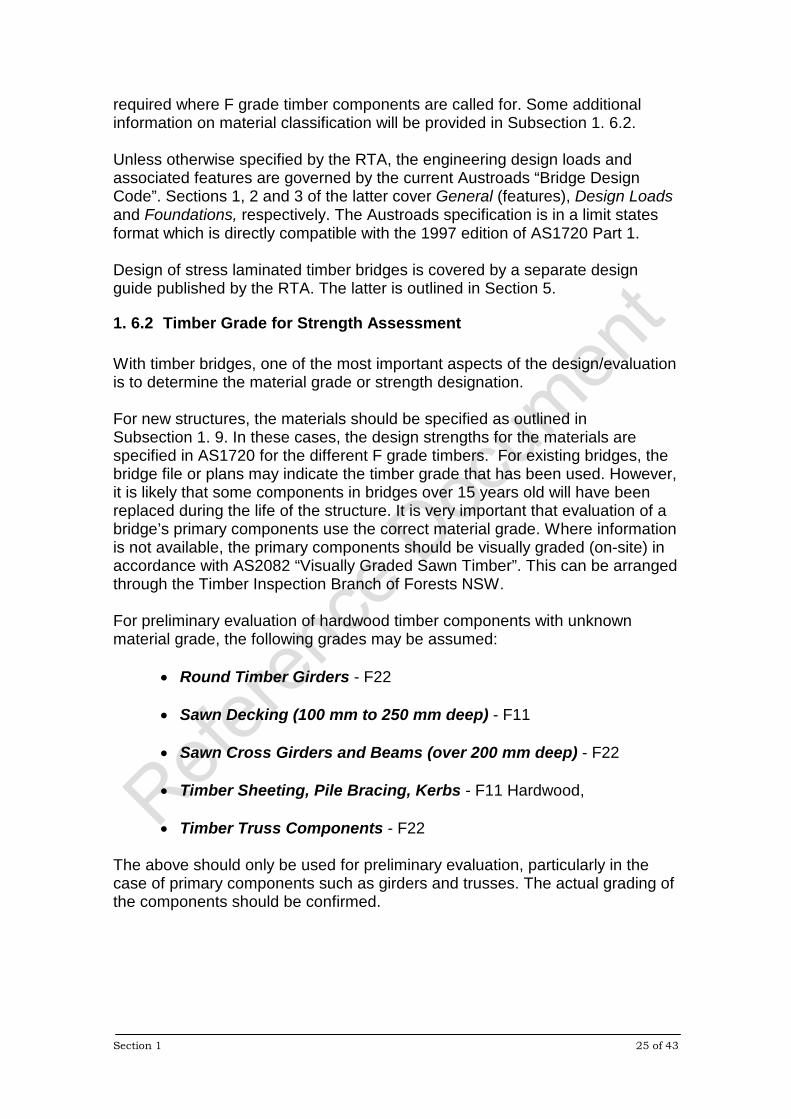
1. 6.2 Timber Grade for Strength Assessment With timber bridges, one of the most important aspects of the design/evaluation is to determine the material grade or strength designation. For new structures, the materials should be specified as outlined in Subsection 1. 9. In these cases, the design strengths for the materials are specified in AS1720 for the different F grade timbers. For existing bridges, the bridge file or plans may indicate the timber grade that has been used. However, it is likely that some components in bridges over 15 years old will have been replaced during the life of the structure. It is very important that evaluation of a bridge’s primary components use the correct material grade. Where information is not available, the primary components should be visually graded (on-site) in accordance with AS2082 “Visually Graded Sawn Timber”. This can be arranged through the Timber Inspection Branch of Forests NSW. For preliminary evaluation of hardwood timber components with unknown material grade, the following grades may be assumed:
• Round Timber Girders - F22 • Sawn Decking (100 mm to 250 mm deep) - F11 • Sawn Cross Girders and Beams (over 200 mm deep) - F22 • Timber Sheeting, Pile Bracing, Kerbs - F11 Hardwood, • Timber Truss Components - F22
The above should only be used for preliminary evaluation, particularly in the case of primary components such as girders and trusses. The actual grading of the components should be confirmed.

Section 1 26 of 43
1. 6.3 Section Properties In most instances, the design drawings for timber bridges specify the nominal section sizes for sawn timbers (eg: 150 mm x 50 mm , 300 mm x 300mm). Experience has shown that the actual timber sizes are usually less than these nominal dimensions either through dressing or drying. Notwithstanding the information below, actual component sizes should be used in the design/evaluation.
1. 6.3.1 New Timber Section Sizes In new construction, material specifications should indicate the required finished section sizes and the design calculations should use these dimensions. Note that AS1720 assumes that the timber is only partially seasoned. It should be noted that where timber is supplied as green (unseasoned or with limited air drying), it will shrink with time as it dries. The section size can reduce by as much as 5% depending on the species. However, the timber usually increases in strength as it dries and, traditionally, it has been assumed that these two conditions will cancel each other out.
1. 6.3.2 Existing Timber Section Sizes In existing structures, existing section sizes should be measured for use in engineering calculations. The section sizes in such bridges can be affected by a number of variables. It is not uncommon to find that even where nominal sizes have been specified, dressed material may have been supplied. The amount of material removed during dressing varies, depending on the member size. In addition, where components have been replaced over the years, they are generally sized green to match the existing (dried) dimension and subsequently shrink during drying resulting in an even smaller section. In summary, the section dimensions for all primary members in an existing bridge should be measured for use in engineering evaluation. It should be noted that AS1720 provides a means of adjusting (increasing) the strength for seasoned timbers based on member size. Some additional information is provided in Subsection 1. 6.4.
Section 1 27 of 43
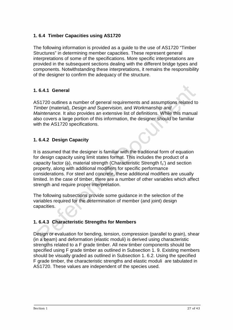
1. 6.4 Timber Capacities using AS1720 The following information is provided as a guide to the use of AS1720 “Timber Structures” in determining member capacities. These represent general interpretations of some of the specifications. More specific interpretations are provided in the subsequent sections dealing with the different bridge types and components. Notwithstanding these interpretations, it remains the responsibility of the designer to confirm the adequacy of the structure.
1. 6.4.1 General AS1720 outlines a number of general requirements and assumptions related to Timber (material), Design and Supervision, and Workmanship and Maintenance. It also provides an extensive list of definitions. While this manual also covers a large portion of this information, the designer should be familiar with the AS1720 specifications.
1. 6.4.2 Design Capacity It is assumed that the designer is familiar with the traditional form of equation for design capacity using limit states format. This includes the product of a capacity factor (φ), material strength (Characteristic Strength fo’) and section property, along with additional modifiers for specific performance considerations. For steel and concrete, these additional modifiers are usually limited. In the case of timber, there are a number of other variables which affect strength and require proper interpretation. The following subsections provide some guidance in the selection of the variables required for the determination of member (and joint) design capacities.
1. 6.4.3 Characteristic Strengths for Members Design or evaluation for bending, tension, compression (parallel to grain), shear (in a beam) and deformation (elastic moduli) is derived using characteristic strengths related to a F grade timber. All new timber components should be specified using F grade timber as outlined in Subsection 1. 9. Existing members should be visually graded as outlined in Subsection 1. 6.2. Using the specified F grade timber, the characteristic strengths and elastic moduli are tabulated in AS1720. These values are independent of the species used.

Section 1 28 of 43
1. 6.4.4 Characteristic Strengths for Bearing and Joints Design or evaluation of bearing (compression perpendicular to grain), timber shear (at joint details), tension perpendicular to grain and joint capacities is derived using characteristic strengths related to strength group classifications. The strength group classification is dependent on the timber species and classifications for many species are tabulated in AS1720 The strength group classifications range from S1 (or SD1) through to S8 (SD8) where the higher number indicates lower strength and D signifies seasoned material. Where the species is not known, the strength group shall be assumed to be S4 (or SD4) for hardwoods and S7 (or SD8) for softwoods. It should be noted that, typically, most hardwoods used for bridges in NSW would not fall below S3 or SD3 and some species are S2 and SD2. In softwoods, the common species are Douglas Fir (commonly called Oregon) and Radiata Pine which are classified as S5 (or SD5) and S6 (or SD6), respectively. In all cases, this is particularly significant as it represents a marked increase in strength for bearing and joint designs compared to the minimum classification assumptions outlined above. However, it should also be noted that in most instances, the design capacity for bearing (perpendicular to grain) such as at supports for girders, beams and decking generally does not govern. Therefore, it is practical to assume the classification for unknown species to perform initial engineering calculations. If this satisfies the conditions, then it would not be necessary to identify the species. This is also significant as it is usually only the design consideration for bending members which requires the strength group classification. All other design considerations require only the F grade timber as outlined in Subsection 1. 6.4.3. Typically, it is valuable to identify the species for the design or evaluation of timber trusses or other structural systems which utilise timber joints and connectors. Original timbers for many older bridges (40 + years) utilised some of the best species such as Iron Bark with a high strength group classification. However, with reduced timber availability over the last few decades, many of these members may have been replaced with lower strength species. Therefore, in both instances, it is important to determine the species for critical members. This can be arranged through the Timber Inspection Branch of Forests NSW.
1. 6.4.5 Capacity Factor φ In general, a capacity factor is applied to a material based on a number of considerations. Particular emphasis is given to the intended application and the variability of the material properties. The latter is generally tied to the method used to determine the material properties. The former is related to the significance of a member’s performance (ie: the consequences of failure).

Section 1 29 of 43
Compared to steel and concrete, the material properties of timber are significantly more variable and so the method used to determine the properties plays a very significant role in determining strength. AS1720 provides an extensive list of φ values for a broad range of conditions and it is not practical to review all of these in this manual. However, in most cases, the timber used in bridges is usually only visually graded. This eliminates a great portion of the tabulation in AS1720. As a result, for visually graded timber (both sawn and round members), the assumed φ values would be as follows:
• 0.65 for primary structural elements • 0.80 for secondary structural elements • 0.60 for primary structural elements intended to fulfil post disaster
functions Some timbers sizes can be machine rated or proof tested as outlined in AS1720. This can significantly improve the reliability of certain material properties, but it also increases the cost. Currently the only bridges which typically use timbers that have had properties verified by testing are SLT systems. These are outlined in Section 5.
1. 6.4.6 Duration of Load Factor k1 Timber has traditionally demonstrated a higher strength for shorter periods of loading than when it is subjected to long term (permanent) loads. In addition, it is believed that the effects of short term loads are cumulative. The standard tests performed to generate the tabulated strength properties in AS1720 represent a 5 minute loading. Since the majority of (cumulative) loads will exceed 5 minutes, it is necessary to apply a factor to modify the strength for the type of loading being considered. AS1720 provides a table of factors for a range of load durations for both timber strength and laterally loaded connections. An appendix is also provided which sets out some typical combinations of different loads (which are of varied durations). However, these are basically derived for use in the design of buildings. Traditionally, only two conditions are generally assumed in the design of timber bridges. First, the components are designed/evaluated under the effects of the dead load (only) of the structure, including superimposed dead loads, assuming a permanent duration of load. This gives a value of k1 equal to 0.57 for both timber and laterally loaded connection strengths. Subsequently, the components are also assessed under a combination of dead plus live loads (including impact) assuming a 5 month duration. This provides k1 values equal to 0.80 for timber and 0.69 for laterally loaded connections. This
Section 1 30 of 43
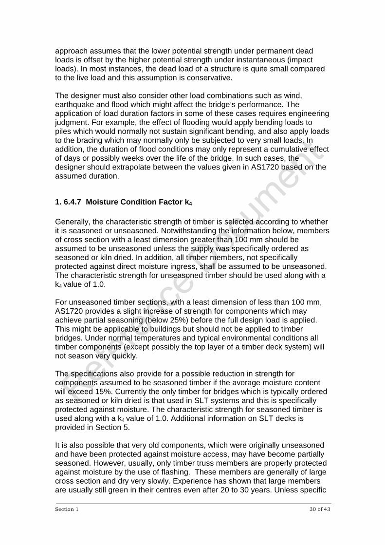
approach assumes that the lower potential strength under permanent dead loads is offset by the higher potential strength under instantaneous (impact loads). In most instances, the dead load of a structure is quite small compared to the live load and this assumption is conservative. The designer must also consider other load combinations such as wind, earthquake and flood which might affect the bridge’s performance. The application of load duration factors in some of these cases requires engineering judgment. For example, the effect of flooding would apply bending loads to piles which would normally not sustain significant bending, and also apply loads to the bracing which may normally only be subjected to very small loads. In addition, the duration of flood conditions may only represent a cumulative effect of days or possibly weeks over the life of the bridge. In such cases, the designer should extrapolate between the values given in AS1720 based on the assumed duration.
1. 6.4.7 Moisture Condition Factor k4 Generally, the characteristic strength of timber is selected according to whether it is seasoned or unseasoned. Notwithstanding the information below, members of cross section with a least dimension greater than 100 mm should be assumed to be unseasoned unless the supply was specifically ordered as seasoned or kiln dried. In addition, all timber members, not specifically protected against direct moisture ingress, shall be assumed to be unseasoned. The characteristic strength for unseasoned timber should be used along with a k4 value of 1.0. For unseasoned timber sections, with a least dimension of less than 100 mm, AS1720 provides a slight increase of strength for components which may achieve partial seasoning (below 25%) before the full design load is applied. This might be applicable to buildings but should not be applied to timber bridges. Under normal temperatures and typical environmental conditions all timber components (except possibly the top layer of a timber deck system) will not season very quickly. The specifications also provide for a possible reduction in strength for components assumed to be seasoned timber if the average moisture content will exceed 15%. Currently the only timber for bridges which is typically ordered as seasoned or kiln dried is that used in SLT systems and this is specifically protected against moisture. The characteristic strength for seasoned timber is used along with a k4 value of 1.0. Additional information on SLT decks is provided in Section 5. It is also possible that very old components, which were originally unseasoned and have been protected against moisture access, may have become partially seasoned. However, usually, only timber truss members are properly protected against moisture by the use of flashing. These members are generally of large cross section and dry very slowly. Experience has shown that large members are usually still green in their centres even after 20 to 30 years. Unless specific
Section 1 31 of 43
moisture readings are taken, the assumed characteristic strength should not be increased.
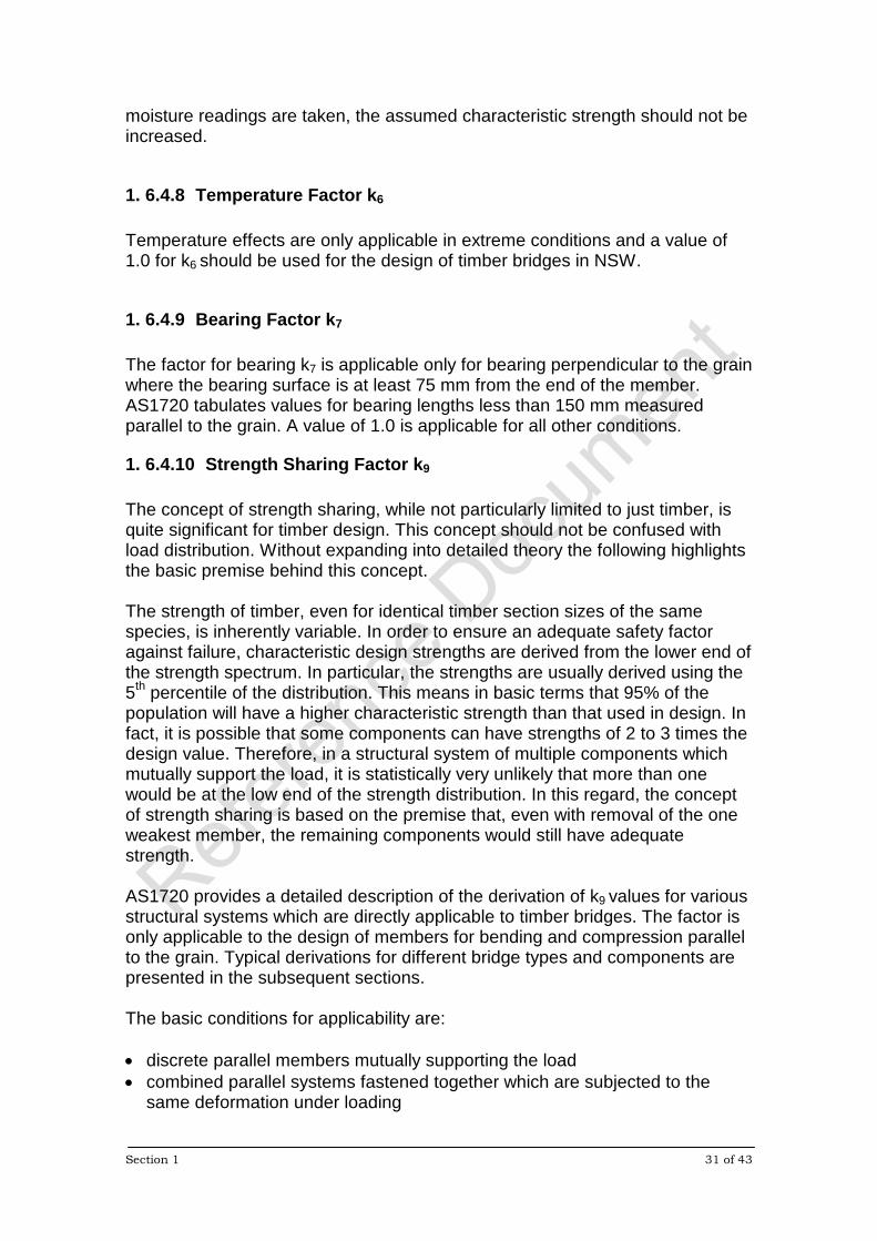
1. 6.4.8 Temperature Factor k6 Temperature effects are only applicable in extreme conditions and a value of 1.0 for k6 should be used for the design of timber bridges in NSW.
1. 6.4.9 Bearing Factor k7 The factor for bearing k7 is applicable only for bearing perpendicular to the grain where the bearing surface is at least 75 mm from the end of the member. AS1720 tabulates values for bearing lengths less than 150 mm measured parallel to the grain. A value of 1.0 is applicable for all other conditions.
1. 6.4.10 Strength Sharing Factor k9 The concept of strength sharing, while not particularly limited to just timber, is quite significant for timber design. This concept should not be confused with load distribution. Without expanding into detailed theory the following highlights the basic premise behind this concept. The strength of timber, even for identical timber section sizes of the same species, is inherently variable. In order to ensure an adequate safety factor against failure, characteristic design strengths are derived from the lower end of the strength spectrum. In particular, the strengths are usually derived using the 5th percentile of the distribution. This means in basic terms that 95% of the population will have a higher characteristic strength than that used in design. In fact, it is possible that some components can have strengths of 2 to 3 times the design value. Therefore, in a structural system of multiple components which mutually support the load, it is statistically very unlikely that more than one would be at the low end of the strength distribution. In this regard, the concept of strength sharing is based on the premise that, even with removal of the one weakest member, the remaining components would still have adequate strength. AS1720 provides a detailed description of the derivation of k9 values for various structural systems which are directly applicable to timber bridges. The factor is only applicable to the design of members for bending and compression parallel to the grain. Typical derivations for different bridge types and components are presented in the subsequent sections. The basic conditions for applicability are: • discrete parallel members mutually supporting the load • combined parallel systems fastened together which are subjected to the
same deformation under loading
Section 1 32 of 43
• support members with overlying systems which are capable of transferring load to other members in the event of failure of one component
1. 6.4.11 Size Factor k11 Traditionally timber has demonstrated an increase in certain material strength properties (bending and tension) as the size of a member is reduced. However, the change in strength is only really significant for the smaller section sizes. The characteristic strengths provided in AS1720 are based on the larger section sizes. AS1720 provides simplified formulas for deriving values of k11 for bending and tension members which are directly applicable to the design of timber bridges.
1. 6.4.12 Stability Factor k12 The stability factor is directly related to the traditional slenderness effects for bending and compression members. AS1720 provides detailed information for the derivation of the stability factor for both bending and compression members. Typical derivations for different bridge types and components are presented in the subsequent sections.
1. 6.5 Structural Analysis for Load Distribution Analysis of timber bridge systems for load distribution should be approached with a measure of judgement. The majority of traditional timber bridge designs utilise systems which do not provide a high degree of composite action or continuity between components. In addition, the systems are usually quite susceptible to the effects of repeated loads and so the structural response can change with time. This is particularly true of the traditional timber girder bridges with transverse decking and sheeting. These systems depend on bolted connections which lose their integrity if not properly maintained. To a lesser degree it also applies to timber trusses. In general, regardless of any refined analytical methods that may be employed (such as grid or frame analysis), a simplified conservative analysis should also be performed for comparison. This simplified method should assume no continuity in members and simple supports. If the simplified method displays inadequate strength, then the two methods should be compared to determine how much improvement in performance would be needed. It is usually unlikely that a timber system will perform as an integral unit except the case of SLT systems. The timber system will perform somewhere between the two conditions and will depend on the bridge condition. The subsequent sections, dealing with the different bridge types, will provide some guidance for the analysis of some of the traditional timber bridge systems.
Section 1 33 of 43
1. 7 DETAILING AND DURABILITY Standard engineering details for typical bridge systems and components are provided throughout this manual. Typically, many details are related to durability aspects of design and construction such as avoiding notches and waterproofing. Reviews of some of the typical detailing that should be applied to all timber bridge systems and components follow. Subsequent sections provide additional information related to the different structural types and components.
1. 7.1 Timber Selection Bridge timber shall be selected to satisfy a number of minimum requirements including strength and durability as outlined in Subsection 1. 9.1. Additional requirements are provided in the subsequent sections for specific bridge types and components. Section 8 also provides additional information on timber durability and protective treatments
1. 7.2 Construction Detailing Proper construction detailing must be provided in order to avoid water traps and unnecessary stress concentrations. Specific attention should given to: • avoiding unnecessary notches • avoiding abrupt changes in section • reducing the potential for end splitting • proper component orientation • avoiding horizontal surfaces • allowing spaces between decking and sheeting • sealing top washer plates and bolt heads • avoiding rebating on top surfaces While the following provides a general review of these considerations, the subsequent sections provide additional information with respect to the different bridge types and components.
1. 7.2.1 Notches and Section Changes Care should be taken when sizing large members at bearings or connections to avoid abrupt section changes which can cause unnecessary stress concentrations. In flexural members this can lead to splitting or crack propagation as shown in Figure 1.7.2.1-1.

Section 1 34 of 43
Figure 1.7.2.1-1 Splitting of Girder at Section Change Deep notches such as the one shown for the bracing in Figure 1.7.2.1-2 also represent poor durability. They create a water trap and also prevent access for inspection and retreatment.
Figure 1.7.2.1-2 Unnecessary Deep Notch for Pile Bracing
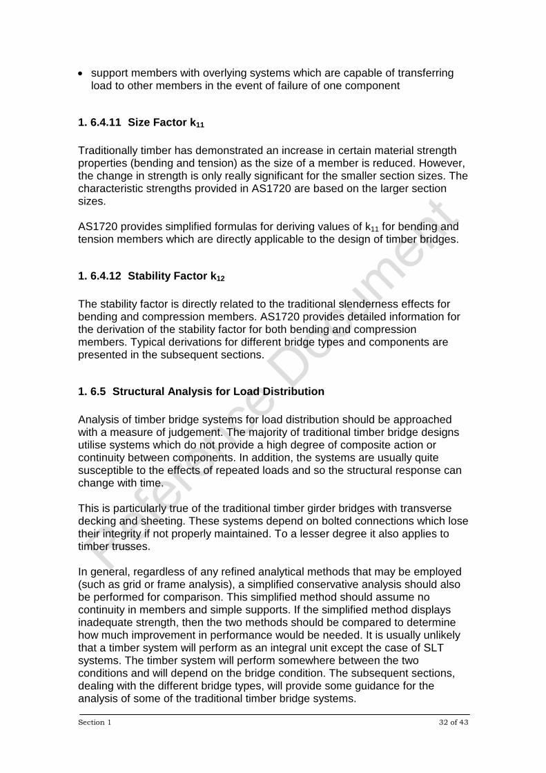
In general, areas which require section changes or flat surfaces for connections should be tapered using a 1 in 5 slope. Two examples of tapered sections are shown in Figure 1.7.2.1-3. However, there are situations where square notches are necessary and examples of these will be outlined in the subsequent sections.
Section 1 35 of 43
Figure 1.7.2.1-3 Required 1 in 5 Taper
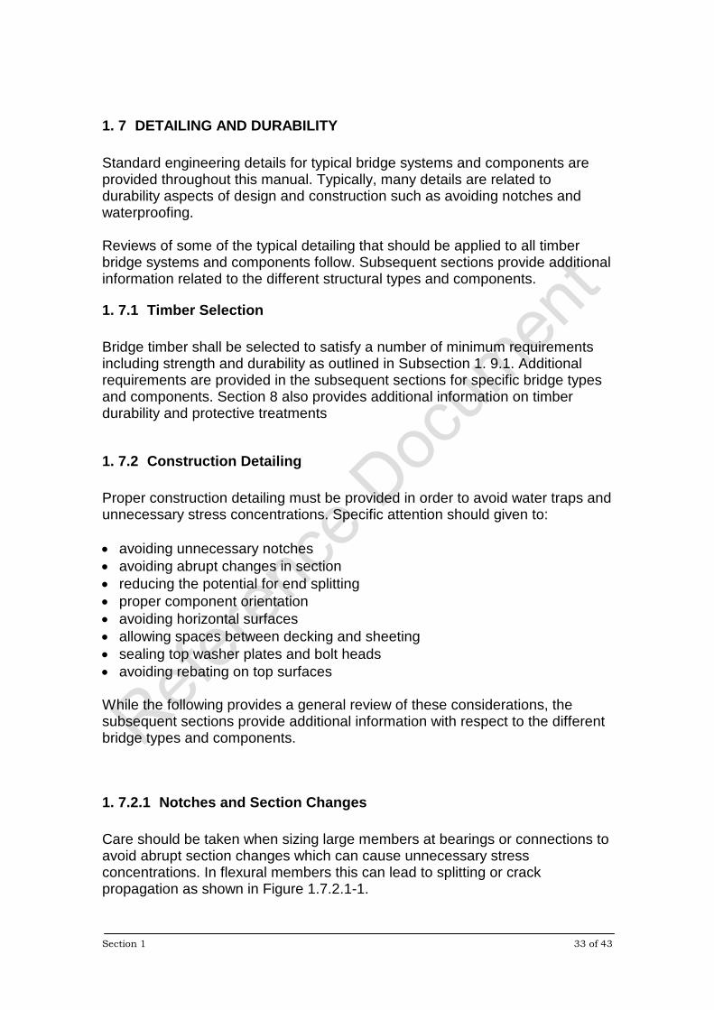
1. 7.2.2 End Split Protection and End Tapers Efforts should be made to reduce the potential for end splits in the larger timber components. End split protection can be applied by using nail plates as shown Figure 1.7.2.2-1. This figure also shows the inward sloping taper at the ends of the members. Such action should be taken for larger components as it reduces the potential for moisture ingress through the ends of the members.
Figure 1.7.2.2-1 End Split Protection and End Tapers
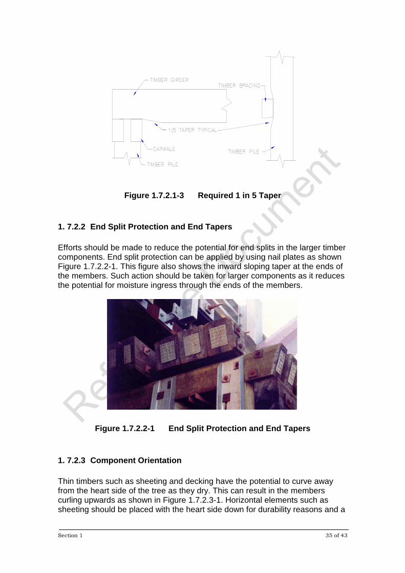
1. 7.2.3 Component Orientation Thin timbers such as sheeting and decking have the potential to curve away from the heart side of the tree as they dry. This can result in the members curling upwards as shown in Figure 1.7.2.3-1. Horizontal elements such as sheeting should be placed with the heart side down for durability reasons and a
Section 1 36 of 43
flush seal surface applied to protect against rapid moisture changes and upward curling.
Figure 1.7.2.3-1 Component Orientation
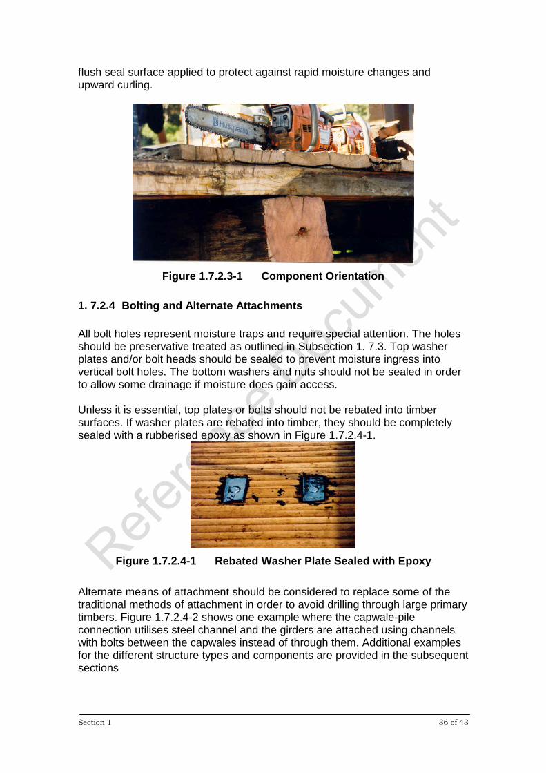
1. 7.2.4 Bolting and Alternate Attachments All bolt holes represent moisture traps and require special attention. The holes should be preservative treated as outlined in Subsection 1. 7.3. Top washer plates and/or bolt heads should be sealed to prevent moisture ingress into vertical bolt holes. The bottom washers and nuts should not be sealed in order to allow some drainage if moisture does gain access. Unless it is essential, top plates or bolts should not be rebated into timber surfaces. If washer plates are rebated into timber, they should be completely sealed with a rubberised epoxy as shown in Figure 1.7.2.4-1.
Figure 1.7.2.4-1 Rebated Washer Plate Sealed with Epoxy
Alternate means of attachment should be considered to replace some of the traditional methods of attachment in order to avoid drilling through large primary timbers. Figure 1.7.2.4-2 shows one example where the capwale-pile connection utilises steel channel and the girders are attached using channels with bolts between the capwales instead of through them. Additional examples for the different structure types and components are provided in the subsequent sections

Section 1 37 of 43
Figure 1.7.2.4-2 Steel Channel Attachments for Capwale and Girders It should also be noted that most attachments can use coach screws instead of bolts. This not only provides tighter holes but also avoids the need to drill completely through the members. Some examples are provided for specific applications in subsequent sections
1. 7.2.5 Other Moisture Trap Conditions There are many additional details which can prevent moisture trap conditions. Where practical, horizontal surfaces should be avoided. In some situations it may be possible to provide a one way crossfall for the entire bridge starting at the supports (using sloped capwales/headstocks). This would provide some slope for nearly all horizontal members in the bridge. Some spacing should be provided in the decking to allow drainage and promote rapid drying.
1. 7.3 Preservative Protection Section 8 provides details on preservative types and applications and should be read to supplement the information given in this subsection. Preservative should be applied to the ends of all members as well as between components and other hidden areas which attract moisture. Bolt holes should be treated using the bolt itself as an applicator, with a gel or grease type remedial preservative to cling to the bolt and fill the void around the bolt. Solid boron rods should be inserted in bore (inspection) holes and the hole plugged as previously mentioned during inspection. This rod will only diffuse in the presence of moisture. Since flashing can actually provide protection for some forms of insect attack, the timber surface under the flashing should be treated to provide an additional barrier.
Section 1 38 of 43
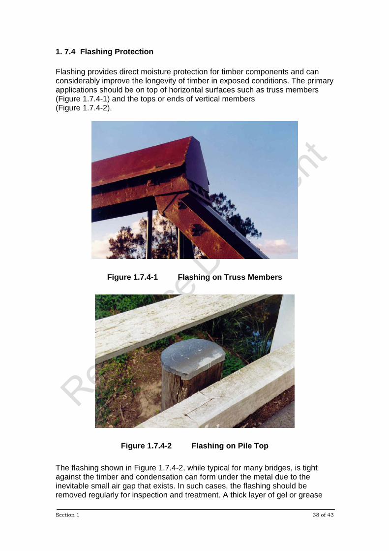
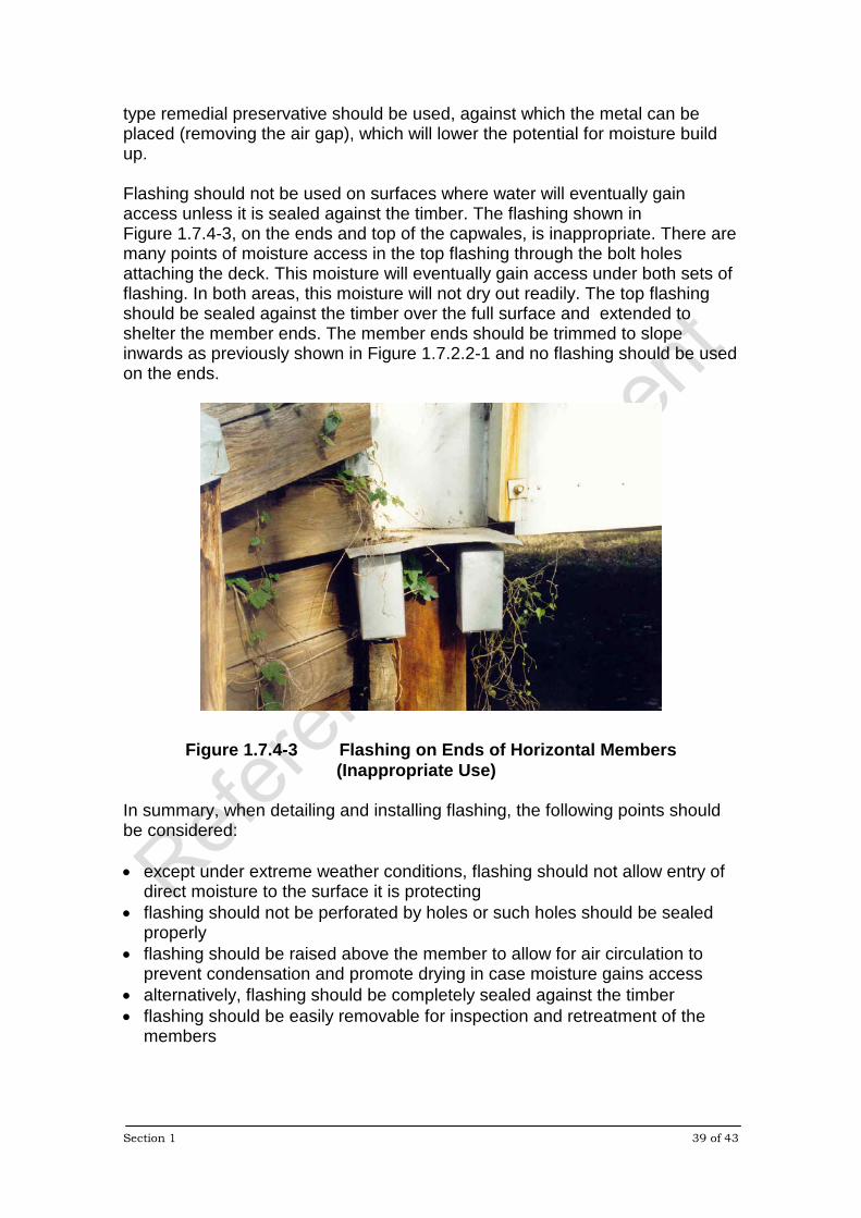
1. 7.4 Flashing Protection Flashing provides direct moisture protection for timber components and can considerably improve the longevity of timber in exposed conditions. The primary applications should be on top of horizontal surfaces such as truss members (Figure 1.7.4-1) and the tops or ends of vertical members (Figure 1.7.4-2).
Figure 1.7.4-1 Flashing on Truss Members
Figure 1.7.4-2 Flashing on Pile Top The flashing shown in Figure 1.7.4-2, while typical for many bridges, is tight against the timber and condensation can form under the metal due to the inevitable small air gap that exists. In such cases, the flashing should be removed regularly for inspection and treatment. A thick layer of gel or grease
Section 1 39 of 43
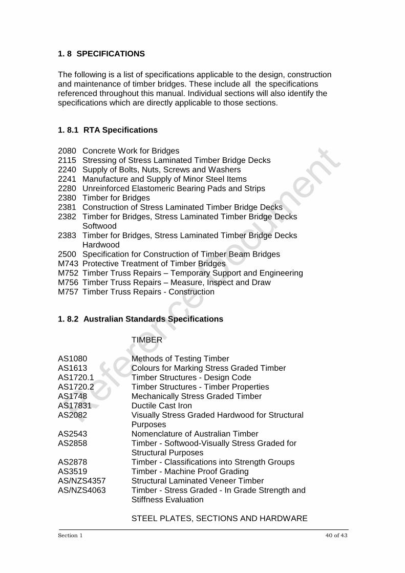
type remedial preservative should be used, against which the metal can be placed (removing the air gap), which will lower the potential for moisture build up. Flashing should not be used on surfaces where water will eventually gain access unless it is sealed against the timber. The flashing shown in Figure 1.7.4-3, on the ends and top of the capwales, is inappropriate. There are many points of moisture access in the top flashing through the bolt holes attaching the deck. This moisture will eventually gain access under both sets of flashing. In both areas, this moisture will not dry out readily. The top flashing should be sealed against the timber over the full surface and extended to shelter the member ends. The member ends should be trimmed to slope inwards as previously shown in Figure 1.7.2.2-1 and no flashing should be used on the ends.
Figure 1.7.4-3 Flashing on Ends of Horizontal Members (Inappropriate Use)
In summary, when detailing and installing flashing, the following points should be considered: • except under extreme weather conditions, flashing should not allow entry of
direct moisture to the surface it is protecting • flashing should not be perforated by holes or such holes should be sealed
properly • flashing should be raised above the member to allow for air circulation to
prevent condensation and promote drying in case moisture gains access • alternatively, flashing should be completely sealed against the timber • flashing should be easily removable for inspection and retreatment of the
members
Section 1 40 of 43
1. 8 SPECIFICATIONS The following is a list of specifications applicable to the design, construction and maintenance of timber bridges. These include all the specifications referenced throughout this manual. Individual sections will also identify the specifications which are directly applicable to those sections.
1. 8.1 RTA Specifications 2080 Concrete Work for Bridges 2115 Stressing of Stress Laminated Timber Bridge Decks 2240 Supply of Bolts, Nuts, Screws and Washers 2241 Manufacture and Supply of Minor Steel Items 2280 Unreinforced Elastomeric Bearing Pads and Strips 2380 Timber for Bridges 2381 Construction of Stress Laminated Timber Bridge Decks 2382 Timber for Bridges, Stress Laminated Timber Bridge Decks
Softwood 2383 Timber for Bridges, Stress Laminated Timber Bridge Decks
Hardwood 2500 Specification for Construction of Timber Beam Bridges M743 Protective Treatment of Timber Bridges M752 Timber Truss Repairs – Temporary Support and Engineering M756 Timber Truss Repairs – Measure, Inspect and Draw M757 Timber Truss Repairs - Construction
1. 8.2 Australian Standards Specifications TIMBER AS1080 Methods of Testing Timber AS1613 Colours for Marking Stress Graded Timber AS1720.1 Timber Structures - Design Code AS1720.2 Timber Structures - Timber Properties AS1748 Mechanically Stress Graded Timber AS17831 Ductile Cast Iron AS2082 Visually Stress Graded Hardwood for Structural Purposes AS2543 Nomenclature of Australian Timber AS2858 Timber - Softwood-Visually Stress Graded for
Structural Purposes AS2878 Timber - Classifications into Strength Groups AS3519 Timber - Machine Proof Grading AS/NZS4357 Structural Laminated Veneer Timber AS/NZS4063 Timber - Stress Graded - In Grade Strength and Stiffness Evaluation STEEL PLATES, SECTIONS AND HARDWARE

Section 1 41 of 43
AS1111 ISO Metric Hexagon Commercial Bolts and Screws AS1163 Structural Steel - Hollow Sections AS1252 High Strength Steel Bolts with Associated Nuts and Washers for Structural Engineering AS1214 Hot-Dip Galvanised Coatings on Threaded Fasteners AS1311 Steel Tendons for Prestressed Concrete- 7-Wire Stress Relieved Steel Strand for Tendons in Prestressed
Concrete AS1313 Steel Tendons for Prestressed Concrete - Cold Worked High-Tensile Alloy Steel Bars for Prestressed Concrete AS1314 Prestressing Anchorages AS1393 Coach Screws AS3678 Structural Steel - Hot Rolled Plates, Floor Plates and
Slabs AS3679.1 Structural Steel - Hot Rolled Bars and Sections AS4100 Steel Structures AS/NZ4680 Hot-Dip Galvanised Coatings on Fabricated Ferrous
Articles
1. 8.3 Austroads Section 1 General Section 2 Design Loads Section 3 Foundations Section 4 Bearings and Deck Joints Section 5 Concrete
1. 9 MATERIAL SUPPLY
1. 9.1 Materials Unless specified otherwise, the material requirements and specifications outlined in this subsection shall apply as minimum requirements for all bridge types. With new designs or major rehabilitation works, it is assumed that design drawings and/or specific construction specifications will be supplied.

Section 1 42 of 43
1. 9.1.1 Timber Supply - General All timber components shall be ordered by specifying size, strength grade (ie: F17, F27), finishing/conditioning (surfaced green or kiln dried) and durability class (or treatment hazard level for softwood, see Section 8). All timber, except that for stress-laminated timber (SLT) decks, shall be supplied in accordance with RTA Form 2380 Timber for Bridges. Timber for SLT decks shall be supplied in accordance with RTA Forms 2382 or 2383 Timber for Bridges - Stress Laminated Timber Decks, Hardwood or Softwood, respectively, as applicable.
1. 9.1.2 Timber Supply - Member Replacements In general, unless otherwise specified, all replacement timber components for existing bridges shall be of equal size, grade and durability class. Only hardwood shall be used to replace existing hardwood members. The following shall be applied as the minimum requirements for replacement of the identified timber components/sizes, unless otherwise specified:
• Round Timber Girders - F27 Hardwood, Group S2, Durability Class 2 to AS1720 (Minimum diameter 450 mm)
• Round Timber Piles - F27 Hardwood, Group S2, Durability Class 1 to AS1720
• Sawn Decking (100 mm to 250 mm deep) - F17 Hardwood, Group
S2, Durability Class 2 to AS1720 • Sawn Cross Girders and Beams (over 200 mm deep) - F27
Hardwood, Group S2, Durability Class 2 to AS1720 • Timber Sheeting, Pile Bracing, Kerbs - F11 Hardwood, Group S2,
Durability Class 2 to AS1720 • Timber Truss Components - F27 Hardwood, Group S2, Durability
Class 1 to AS1720
Section 1 43 of 43
1. 9.1.3 Steel Hardware The material requirements for plates, bolts, nuts, washers and coach screws to be used for specific applications (eg: connection of sheeting, decking, girders), will be provided in the subsequent sections dealing with those specific applications. In general, unless otherwise specified, all steel hardware used for general maintenance repairs/replacements shall satisfy the following minimum requirements; • Steel plate shall be Grade 250 to AS 3678 • Steel sections shall be Grade 300 to AS 3679.1 • Bolts, coach screws, nuts and washers shall be supplied to RTA Form 2240 • Bolts shall be Grade 4.6 to AS 1111 • All steel plates and sections shall be galvanised to AS/NZ 4680 and bolts,
coach screws, and associated nuts and washers shall be galvanised to AS 1214.