vibration response of long cable-stayed timber foot bridge ... · vibration response of long...
TRANSCRIPT
Vibration response of long cable-stayed timber footbridge – case study
Robert Kliger Chalmers Univ. of Technology Div. of Structural Engineering SE-412 98 Gothenburg Sweden [email protected]
Ph.D. Professor of Steel and Timber Structures. His research focuses on the structural behavior of built-up wood-based panels with semi-rigid connections, wood properties, timber products, strengthening of structures, in-situ assessment of timber structures and timber bridges.
Tomas Svensson COWI AB Box 12076, SE- 402 41Gothenburg Sweden [email protected]
Technical Director and Project Manager at Major Bridges and Marine Structures. Civil engineer with more than 30 years’ experience of structural engineering within the fields of buildings, industry and bridges.
Hanna Jansson COWI AB, Box 12076, SE-402 41Gothenburg Sweden [email protected]
MSc in Civil Engineering, Consultant and Coordinator at Major Bridges. Civil engineer specializing in structural engineering within the field of bridges.
Isak Svensson COWI AB Box 12076, SE-402 41Gothenburg Sweden [email protected]
MSc in Civil Engineering, Consultant and Coordinator at Major Bridges. Civil engineer specializing in structural engineering within the field of bridges.
Summary
Timber footbridges with a span larger than 30 meters are sensitive to vibrations and dynamic factors must therefore be taken into considerations in the design. A case study of a cable-stayed footbridge, Älvsbacka Bridge, with a free span of 130 meters, is presented. The dynamic design of the bridge is compared, based on the old Swedish code, BRO 2004 and the Eurocode 5. Simplified force models presented in BRO 2004 and the ISO 10137 international standard are compared. Vertical and lateral accelerations are measured on the bridge with accelerometers attached to the bridge deck. According to the simplified force model, the vertical acceleration limit was met for a group of twenty pedestrians, which was regarded as a reasonable design situation. From the measured accelerations, the damping factor was calculated as 1.2% of critical damping, which is twice the value used in design. Keywords: pedestrian bridge, dynamic response, force models, damping
1. Introduction The cable-stayed timber footbridge, Älvsbacka Bridge, was completed during the summer of 2011 in the center of the City of Skellefteå in the north of Sweden. The bridge has a free span of 130

Kliger, T. Svensson,
Jansson and I. Svensson: Vibration response of long cable-stayed timber footbridge – case study
International Conference on Timber Bridges 2013- Las Vegas, Nevada USA
meters, making it the largest cable-stayed timber bridge in Scandinavia to date. The client was the Municipality of Skellefteå, the contractor was Martinsons Träbroar AB and the structural engineering consultant was COWI AB. Älvsbacka Bridge was designed according to the Swedish Road Administration Bridge Code BRO 2004 [1], but since 2009 the Eurocode 5 [2] has been applied in all designs. The effects on the dynamic design of the transition between two codes, i.e. Eurocode to BRO 2004, are studied and the findings are related to useful experience for future projects. Timber footbridges with a span greater than 30 meters are sensitive to vibrations and dynamic considerations are therefore very important in the design [3]. One source of vibrations is pedestrian traffic and a special loading situation is caused by a group of pedestrians walking at the same tempo on the bridge. This loading situation was one of the greatest challenges when designing Älvsbacka Bridge, together with predicting how the dynamic behavior of the modeled bridge would correlate to the real response of the bridge. The general design rules in Eurocode 5 when it comes to vibrations in timber footbridges state that a footbridge should be designed in such a way that the loads on the bridge do not result in uncomfortable vibrations for the users [2]. According to the part which applies to timber bridges, Eurocode 5, Part 2, [4] the vibration serviceability criteria include a limit for the first resonance frequency induced by pedestrians and a limit for an acceptable level of vertical acceleration. The acceleration limit is strongly dependent on the damping ratio of the structure. During the design process, the damping ratio from BRO 2004 was twice the value proposed in the Eurocode [4] and, as a result, the Eurocode value was used, resulting in lower accelerations. The aim of this paper is to report whether the assumption of the damping ratio from the Eurocode was more reasonable than that from BRO 2004 and, using measurements in situ, to ascertain whether the acceleration limits were met. The results presented in this paper focus on the vertical accelerations, as the maximum measured lateral acceleration was 0.14 m/s2 and this value complied with all the design requirements.
2. Guidelines and codes – force models and comfort criteria There are various guidelines to reduce the risk of pedestrians experiencing discomfort or feeling unsafe due to vibrations when crossing a footbridge. The design guidelines recommended by various countries set limits based on so-called comfort criteria and assume that within these limits most people do not feel any disturbance as a result of the vibrations in the bridge. The most common factors that are set as limit values are either the natural frequency or the acceleration. The acceleration is usually expressed in terms of maximum permitted acceleration in the bridge deck. There are many guidelines and codes in which various force models and the relevant comfort criteria are proposed. However, in this paper, only the relevant two codes are discussed and compared with regulations proposed by the international ISO 10137 standard [5]. BRO 2004 was published by the Swedish Road Administration and, until 2009, it was the Swedish standard for bridge design. This code was replaced by the Eurocode, but, for projects procured before 2009, it is still allowed to use BRO 2004 as the design code. The structural design of Älvsbacka Bridge was procured before 2009 and, as result, BRO 2004 was the valid design code for this project. The force model from BRO 2004 for pedestrian loading on footbridges is a harmonic vertical concentrated force which should be placed at the most critical point of the bridge deck. When designing according to BRO 2004, a damping factor of 0.6% of critical damping should be used. The first vertical natural frequency of the bridge deck should be higher than 3.5 Hz. If the first natural frequency is below 3.5 Hz, a maximum limit value for the vertical acceleration of the bridge deck is 0.7 m/s2. No requirements or recommendations for lateral vibrations were given in BRO 2004.
Kliger, T. Svensson,
Jansson and I. Svensson: Vibration response of long cable-stayed timber footbridge – case study
International Conference on Timber Bridges 2013- Las Vegas, Nevada USA
In Eurocode 5, a simplified method for calculating vertical vibrations in timber bridges is given. The method applies to simply supported or truss bridges but not to other bridge types. Instead, it is stated that other methods may be specified in the national annex or for each individual project. In Eurocode 5, the damping factor for structures with mechanical joints is set at 1.5%, which can be used if no other value is stated in the national annex [2]. A check of the maximum peak acceleration in all directions must be made if the first natural frequency of the bridge deck is less than 5 Hz for vertical vibrations or less than 2.5 Hz for lateral and torsional vibrations. The maximum permissible accelerations according to Eurocode are 0.7, 02 and 0.4 m/s2, depending on the direction of acceleration and load; i.e. for vertical acceleration, lateral acceleration for normal use and exceptional crowd conditions respectively. These accelerations should be met by a considerable margin due to large-scale uncertainty in the calculation of the response. The resulting vertical and horizontal acceleration is calculated differently depending on whether it is caused by one person or a group of people crossing the bridge and depending on the natural frequency, mass of the bridge and damping ratio. In the Swedish national annex [6], no force model for the pedestrian force is given. Instead, it is the client who is expected to choose the appropriate force model for the dynamic force, in the same way as for the comfort criteria. In the international ISO 10137 standard, the force from a pedestrian is described by the static weight of the pedestrian and the corresponding periodic dynamic contribution. Both the vertical and lateral components of the dynamic pedestrian force are represented with the same equation [5]. The difference between vertical and lateral direction is made using the numerical coefficient. There are different values for the two coefficients for one moving pedestrian. The action from a group of people crossing the bridge is expressed by multiplying a coordination factor by the total pedestrian force. The coordination factor aims to describe the number of people in the group that tend to walk at the same tempo. The vibrations of footbridges are based on different design situations that occur during the design life of the bridge.
10
010
110
210-1
100
101
Frequency [Hz]
Acc
ele
ratio
n lim
it (r
.m.s
) [m
/s2]
Vertical acceleration limit, factor 60Vertical acceleration limit, factor 30Lateral acceleration limit, factor 60
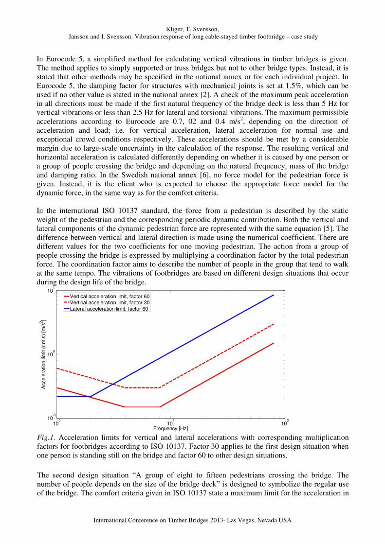
Fig.1. Acceleration limits for vertical and lateral accelerations with corresponding multiplication factors for footbridges according to ISO 10137. Factor 30 applies to the first design situation when one person is standing still on the bridge and factor 60 to other design situations. The second design situation “A group of eight to fifteen pedestrians crossing the bridge. The number of people depends on the size of the bridge deck” is designed to symbolize the regular use of the bridge. The comfort criteria given in ISO 10137 state a maximum limit for the acceleration in

Kliger, T. Svensson,
Jansson and I. Svensson: Vibration response of long cable-stayed timber footbridge – case study
International Conference on Timber Bridges 2013- Las Vegas, Nevada USA
the vertical and lateral direction respectively. The limits for each direction depend on a specific base curve multiplied by a certain factor. The base curves for vertical and lateral accelerations are shown in Fig. 1. [5].
3. Älvsbacka Bridge Älvsbacka Bridge is a symmetrical cable-stayed bridge with one span of 130 meters and two pylons, shown in Fig2. The bridge deck is slightly curved where the mid-point is about one meter above the end points. The height of the pylons is 23 meters and one pylon consists of two glulam columns with four glulam cross-beams and steel cross-bracing to stabilize the pylon. The main beam consists of three glulam beams glued together, creating one beam with the dimensions of 645 x 1,125 mm. The main beams, see Fig. 2C, are supported by steel cross-beams every 16.25 meters to which the cables are connected at each side. Glulam cross-beams connect the two main beams with a distance of 2.5 meters. On top of the glulam cross-beams, purlins are placed to carry the deck of wooden planks. To stabilize the bridge deck, steel cross-bracing is used. The main beams of the deck and the cross-beams and columns of the pylons are covered with yellow painted panels for weather protection.
A)
B)
C) Fig. 2 A) Overview of the bridge, B) The south pylon of Älvsbacka Bridge with its anchorage cables and concrete foundations, C) The main beams are supported by steel cross-beams to which the cables are attached.
4. Design FE models of the bridge The dynamic design of Älvsbacka Bridge was carried out by COWI in Gothenburg in cooperation with the Division for Aerodynamics from COWI Denmark. The finite element software called NEiNastran with the pre- and postprocessor Femap was used for the dynamic analyses of Älvsbacka Bridge. This original design analysis included both the impact of wind and the corresponding aerodynamic instability and the dynamic effects of pedestrian traffic. In this case study, the FE model was made using Brigade/Plus software to analyze the pedestrian-induced vibrations using linear analysis and referred to as a simple model. Input data in both the original and simple models were taken from BRO 2004, see Table 1.
Kliger, T. Svensson,
Jansson and I. Svensson: Vibration response of long cable-stayed timber footbridge – case study
International Conference on Timber Bridges 2013- Las Vegas, Nevada USA
Once the simple linear model was verified against the original design by COWI, the same model was run once more with new input data provided by the Eurocode. The difference in terms of results between the original COWI design model and the simple linear model was very small, i.e. the deflection due to the uniformly distributed pedestrian load of 4 kN/m2 was 166 mm and 164 mm respectively and the first vertical natural frequency was 1.448 Hz and 1.441 Hz respectively. Table 1 Input data according to BRO 2004 and Eurocode 5.
Young’s modulus [GPa]
Poisson’s ratio
Density [kg/m3]
Shear modulus [GPa]
BRO 2004
Deck 4.846 - 454 0.323
Glulam 13 0.4 600 4.643
EC 5 Deck 5.923 - 259 0.372
Glulam 13.7 0.4 430 4.893
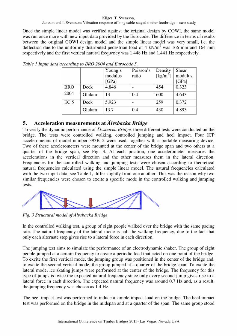
5. Acceleration measurements at Älvsbacka Bridge To verify the dynamic performance of Älvsbacka Bridge, three different tests were conducted on the bridge. The tests were controlled walking, controlled jumping and heel impact. Four ICP accelerometers of model number 393B12 were used, together with a portable measuring device. Two of these accelerometers were mounted at the center of the bridge span and two others at a quarter of the bridge span, see Fig. 3. At each position, one accelerometer measures the accelerations in the vertical direction and the other measures them in the lateral direction. Frequencies for the controlled walking and jumping tests were chosen according to theoretical natural frequencies calculated using the simple linear model. The natural frequencies calculated with the two input data, see Table 1, differ slightly from one another. This was the reason why two similar frequencies were chosen to excite a specific mode in the controlled walking and jumping tests.
Fig. 3 Structural model of Älvsbacka Bridge In the controlled walking test, a group of eight people walked over the bridge with the same pacing rate. The natural frequency of the lateral mode is half the walking frequency, due to the fact that only each alternate step gives rise to a lateral force in each direction. The jumping test aims to simulate the performance of an electrodynamic shaker. The group of eight people jumped at a certain frequency to create a periodic load that acted on one point of the bridge. To excite the first vertical mode, the jumping group was positioned in the center of the bridge and, to excite the second vertical mode, the group jumped at a quarter of the bridge span. To excite the lateral mode, ice skating jumps were performed at the center of the bridge. The frequency for this type of jumps is twice the expected natural frequency since only every second jump gives rise to a lateral force in each direction. The expected natural frequency was around 0.7 Hz and, as a result, the jumping frequency was chosen as 1.4 Hz. The heel impact test was performed to induce a simple impact load on the bridge. The heel impact test was performed on the bridge in the midspan and at a quarter of the span. The same group stood

Kliger, T. Svensson,
Jansson and I. Svensson: Vibration response of long cable-stayed timber footbridge – case study
International Conference on Timber Bridges 2013- Las Vegas, Nevada USA
on their toes close together and fell back on their heels at the same time. This procedure for both the jumping and impact tests was repeated twice with a 30-second interval during which all the test participants stood still. The purpose of the tests was to estimate a damping factor.
6. Results
6.1 Force amplitudes for dynamic pedestrian forces
The force amplitudes for the different force models are presented in Table 2. The static weight of a pedestrian is included in the force amplitude in the ISO 10137 model, which in this study is assumed to be 80 kg. The sum of the first three -factors that are used in the simplified ISO 10137 force model is 0.3. No force model related to lateral vibrations was given in BRO 2004. Instead, 10% of the vertical force is assumed to act as a lateral force in the calculations. The different loads are all harmonic periodic forces and the resulting accelerations were calculated over a frequency sweep from 0 to 5 Hz. One of the recommended design situations in ISO 10137 is a stream of pedestrians significantly larger than fifteen pedestrians. In the simplified force model, a group of fifty pedestrians was chosen. Table 2 Force amplitudes for the dynamic pedestrian forces applied in BRO 2004 and ISO 10137. These values are used to calculate accelerations in the bridge deck.
Code Vertical force amplitude [N]
Lateral force amplitude [N]
BRO 2004 1082 108
ISO 10137, 1 runner 1520 160
ISO 10137, 1 pedestrian 240 80
ISO 10137, 10 pedestrians 760 250
ISO 10137, 50 pedestrians 1700 565
6.2 Performed measurements at the bridge
6.2.1 Controlled walking test
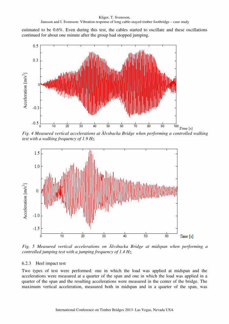
Measured vertical accelerations from one of the controlled walking tests are shown in Fig. 4. The measured accelerations never exceeded 0.5 m/s2. The data are measured at a quarter of the span with eight people walking on the bridge with a walking frequency of 1.9 Hz. The accelerations were the highest when the group passed a quarter of the bridge span, but, when the group passed the midspan, the accelerations were smaller. One of the intentions of the controlled walking tests was to excite the bridge in the lateral direction. The maximum lateral acceleration measured in the midspan from a test with 1.5 Hz as the walking frequency was 0.037 m/s2. On both test occasions, the cables of the bridge started to sway from the applied forces in the controlled walking tests, but the oscillations decayed as soon as the group had left the bridge.
6.2.2 Jumping test
The largest measured vertical acceleration from the jumping tests was 1.66 m/s2, as shown in Fig. 5. After 30 seconds, the group stopped jumping and stood still as the accelerations decreased. The results from the jumping tests were used to calculate a damping factor of the bridge. One of the fitted curves using MATLAB with decaying accelerations is shown in Fig. 6. Taking the results from all the jumping tests into account, the approximate damping factor from the jumping tests is
Kliger, T. Svensson,
Jansson and I. Svensson: Vibration response of long cable-stayed timber footbridge – case study
International Conference on Timber Bridges 2013- Las Vegas, Nevada USA
estimated to be 0.6%. Even during this test, the cables started to oscillate and these oscillations continued for about one minute after the group had stopped jumping.
Acc
eler
atio
n [m
/s2 ]
Time [s] Fig. 4 Measured vertical accelerations at Älvsbacka Bridge when performing a controlled walking test with a walking frequency of 1.9 Hz.
Acc
eler
atio
n [m
/s2 ]
Fig. 5 Measured vertical accelerations on Älvsbacka Bridge at midspan when performing a controlled jumping test with a jumping frequency of 1.4 Hz.
6.2.3 Heel impact test
Two types of test were performed: one in which the load was applied at midspan and the accelerations were measured at a quarter of the span and one in which the load was applied in a quarter of the span and the resulting accelerations were measured in the center of the bridge. The maximum vertical acceleration, measured both in midspan and in a quarter of the span, was
Kliger, T. Svensson,
Jansson and I. Svensson: Vibration response of long cable-stayed timber footbridge – case study
International Conference on Timber Bridges 2013- Las Vegas, Nevada USA
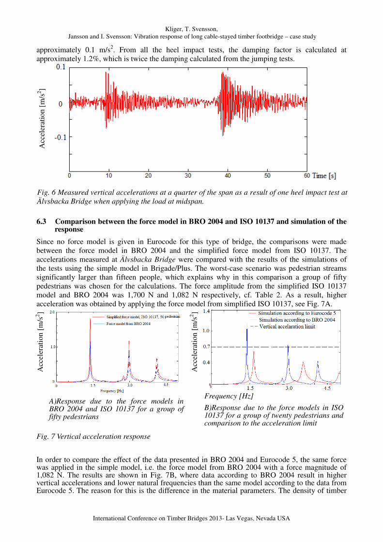
approximately 0.1 m/s2. From all the heel impact tests, the damping factor is calculated at approximately 1.2%, which is twice the damping calculated from the jumping tests.
Acc
eler
atio
n [m
/s2 ]
Fig. 6 Measured vertical accelerations at a quarter of the span as a result of one heel impact test at Älvsbacka Bridge when applying the load at midspan.
6.3 Comparison between the force model in BRO 2004 and ISO 10137 and simulation of the response
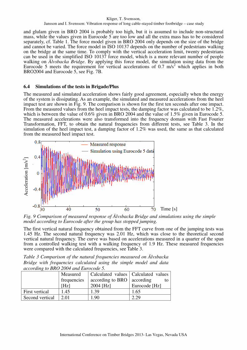
Since no force model is given in Eurocode for this type of bridge, the comparisons were made between the force model in BRO 2004 and the simplified force model from ISO 10137. The accelerations measured at Älvsbacka Bridge were compared with the results of the simulations of the tests using the simple model in Brigade/Plus. The worst-case scenario was pedestrian streams significantly larger than fifteen people, which explains why in this comparison a group of fifty pedestrians was chosen for the calculations. The force amplitude from the simplified ISO 10137 model and BRO 2004 was 1,700 N and 1,082 N respectively, cf. Table 2. As a result, higher acceleration was obtained by applying the force model from simplified ISO 10137, see Fig. 7A.
Acc
eler
atio
n [m
/s2 ]
A)Response due to the force models in BRO 2004 and ISO 10137 for a group of fifty pedestrians
Acc
eler
atio
n [m
/s2 ]
Frequency [Hz]
B)Response due to the force models in ISO 10137 for a group of twenty pedestrians and comparison to the acceleration limit
Fig. 7 Vertical acceleration response
In order to compare the effect of the data presented in BRO 2004 and Eurocode 5, the same force was applied in the simple model, i.e. the force model from BRO 2004 with a force magnitude of 1,082 N. The results are shown in Fig. 7B, where data according to BRO 2004 result in higher vertical accelerations and lower natural frequencies than the same model according to the data from Eurocode 5. The reason for this is the difference in the material parameters. The density of timber
Kliger, T. Svensson,
Jansson and I. Svensson: Vibration response of long cable-stayed timber footbridge – case study
International Conference on Timber Bridges 2013- Las Vegas, Nevada USA
and glulam given in BRO 2004 is probably too high, but it is assumed to include non-structural mass, while the values given in Eurocode 5 are too low and all the extra mass has to be considered separately, cf. Table 1. The force model given in BRO 2004 only depends on the size of the bridge and cannot be varied. The force model in ISO 10137 depends on the number of pedestrians walking on the bridge at the same time. To comply with the vertical acceleration limit, twenty pedestrians can be used in the simplified ISO 10137 force model, which is a more relevant number of people walking on Älvsbacka Bridge. By applying this force model, the simulation using data from the Eurocode 5 meets the requirement for vertical accelerations of 0.7 m/s2 which applies in both BRO2004 and Eurocode 5, see Fig. 7B.
6.4 Simulations of the tests in Brigade/Plus
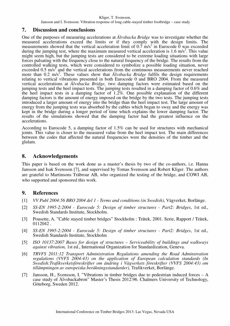
The measured and simulated acceleration shows fairly good agreement, especially when the energy of the system is dissipating. As an example, the simulated and measured accelerations from the heel impact test are shown in Fig. 9. The comparison is shown for the first ten seconds after one impact. From the measured values from the heel impact tests, the damping factor was calculated to be 1.2%, which is between the value of 0.6% given in BRO 2004 and the value of 1.5% given in Eurocode 5. The measured accelerations were also transformed into the frequency domain with Fast Fourier Transformation, FFT, to obtain the natural frequencies from different tests, see Table 3. In the simulation of the heel impact test, a damping factor of 1.2% was used, the same as that calculated from the measured heel impact test.
Acc
eler
atio
n [m
/s2 ]
Time [s]
Fig. 9 Comparison of measured response of Älvsbacka Bridge and simulations using the simple model according to Eurocode after the group has stopped jumping.
The first vertical natural frequency obtained from the FFT curve from one of the jumping tests was 1.45 Hz. The second natural frequency was 2.01 Hz, which was close to the theoretical second vertical natural frequency. The curve was based on accelerations measured in a quarter of the span from a controlled walking test with a walking frequency of 1.9 Hz. These measured frequencies were compared with the calculated frequencies, see Table 3.
Table 3 Comparison of the natural frequencies measured on Älvsbacka Bridge with frequencies calculated using the simple model and data according to BRO 2004 and Eurocode 5.
Measured frequencies [Hz]
Calculated values according to BRO 2004 [Hz]
Calculated values according to Eurocode [Hz]
First vertical 1.45 1.39 1.65 Second vertical 2.01 1.90 2.29
Kliger, T. Svensson,
Jansson and I. Svensson: Vibration response of long cable-stayed timber footbridge – case study
International Conference on Timber Bridges 2013- Las Vegas, Nevada USA
7. Discussion and conclusions
One of the purposes of measuring accelerations at Älvsbacka Bridge was to investigate whether the measured accelerations exceed the limits or if they comply with the design limits. The measurements showed that the vertical acceleration limit of 0.7 m/s2 in Eurocode 0 was exceeded during the jumping test, where the maximum measured vertical acceleration is 1.6 m/s2. This value might seem high, but the jumping tests are considered to be extreme loading situations with large forces pulsating with the frequency close to the natural frequency of the bridge. The results from the controlled walking tests, which were considered to symbolize a possible loading situation, never exceeded 0.5 m/s2 and the vertical accelerations from the continuous measurements never reached more than 0.2 m/s2. These values show that Älvsbacka Bridge fulfils the design requirements relating to vertical vibrations presented in both Eurocode 0 and BRO 2004. From the measured vertical accelerations at Älvsbacka Bridge, two damping factors were estimated based on the jumping tests and the heel impact tests. The jumping tests resulted in a damping factor of 0.6% and the heel impact tests in a damping factor of 1.2%. One possible explanation of the different damping factors is the amount of energy imposed on the bridge by the two tests. The jumping tests introduced a larger amount of energy into the bridge than the heel impact test. The large amount of energy from the jumping tests was absorbed by the cables which began to sway and the energy was kept in the bridge during a longer period of time which explains the lower damping factor. The results of the simulations showed that the damping factor had the greatest influence on the accelerations.
According to Eurocode 5, a damping factor of 1.5% can be used for structures with mechanical joints. This value is closer to the measured value from the heel impact test. The main differences between the codes that affected the natural frequencies were the densities of the timber and the glulam.
8. Acknowledgements
This paper is based on the work done as a master’s thesis by two of the co-authors, i.e. Hanna Jansson and Isak Svensson [7], and supervised by Tomas Svensson and Robert Kliger. The authors are grateful to Martinsons Träbroar AB, who organized the testing of the bridge, and COWI AB, who supported and sponsored this work.
9. References
[1] VV Publ 2004:56 BRO 2004 del 1 - Terms and conditions (in Swedish), Vägverket, Borlänge.
[2] SS-EN 1995-2:2004 - Eurocode 5: Design of timber structures - Part2: Bridges, 1st ed., Swedish Standards Institute, Stockholm.
[3] Pousette, A. ”Cable stayed timber bridges” Stockholm : Trätek, 2001. Serie, Rapport / Trätek, 0112042 .
[4] SS-EN 1995-2:2004 - Eurocode 5: Design of timber structures - Part2: Bridges, 1st ed., Swedish Standards Institute, Stockholm
[5] ISO 10137:2007 Bases for design of structures – Serviceability of buildings and walkways against vibration, 1st ed., International Organization for Standardization, Geneva.
[6] TRVFS 2011:12 Transport Administration Regulations amending the Road Adminstration regulations (VVFS 2004:43) on the application of European calculation standards (In Swedish:Trafikverketsföreskrifter om ändring i Vägverkets föreskrifter (VVFS 2004:43) om tillämpningen av europeiska beräkningsstandarder), Trafikverket, Borlänge.
[7] Jansson, H., Svensson, I. ”Vibrations in timber bridges due to pedestrian induced forces – A case study of Älvsbackabron” Master’s Thesis 2012:96. Chalmers University of Technology, Göteborg, Sweden 2012.